SlideShare a Scribd company logo
EXPERIMENT NO. 1
AIM:
To study and design the implementation of trajectory path of the robot using parallel loop
algorithm
Apparatus Used:
Microsoft Windows XP, Professional Version 2002, Intel® Pentium® Dual CPU. E2180 @2.00
GHz, 2.00 GHz, 199 GB of RAM, Lab VIEW Robotics 2011 SP1
Theory:
LabVIEW (short for The Laboratory Virtual Instrumentation Engineering Workbench) is
a platform and development environment for a visual programming language from National
Instruments in which you create programs using a graphical natation(connecting functional
nodes via wires through which data flows), in this regard, it differs from traditional programming
languages like C, C++, or Java in which you program with text. However LabVIEW is much
more than a programming language. It is an interactive program development and execution
system designed for people, like scientists and engineers, who need to program as part of their
jobs. The LabVIEW development environment works on computers running Windows, Mac OS
X, or Linux. Labview can create programs that run on those platforms, as well as Microsoft
Pocket PC Microsoft windows CE, Palm OS, and a variety of embedded platforms, including
Field Programmable Gate Arrays (FPGAs), Digital Signal Processors (DSP), and
Microprocessors.
Procedure:
Execution is determined by the structure of a graphical block diagram on which the
programmer connects different function nodes by drawing wires. These wires propagate
variables and any node can execute as soon as all its input data become available. Labview ties
the creation of user interface (front panels) into the development cycle. Labview
programs/subroutines are called virtual instruments (VIs). Each VI has three components; a
block diagram, a front panel, and a connector panel. The last is used to represent the VI in the
block diagram of other, calling vi. Controls and indicators on the front panel allow an operator to
input data into or extract data from a running virtual instrument. However, the front panel can
also serve as a programmatic interface. Thus a VI can either be run as a program, with the front
panel serving as a user interface, or when dropped as a node onto the block diagram, the font
panel defines the inputs and outputs for the given node through the connector pane. This implies
each VI can be easily tested before being embedded as a subroutine into a larger program. The
graphical approach also allows non-programmers to build programs simply by dragging and
dropping virtual representation of lab equipment with which they are already familiar.
Execution of VI’s and Sub-VI’s:
Main VI:
The goal is chosen at random in the Mission Planning VI. Typically, the goal is provided by
some external input, or a stored sequence of sub goals. Adjust the Mission Planning VI to
establish goals for your situation. The timing of the control loops in this example is somewhat
arbitrary. (5 sec/iteration for the mission planning loop). Adjust these to suit your requirements.
Typically, a robot will have sensors. Sensors that affect navigation, such as range finder used for
obstacle avoidance, could be read insight of the navigation loop. For other sensors, you may
want to add additional Vis to read and process the sensor data.
a) Front Panel:
b) Block Diagram:
1. Mission Planning Loop
The Mission Planning Loop establishes the "goal" of the robot. In this, we randomly
compute a new goal whenever we've reached the last goal. This loop could be modified
to iterate through a sequence of goals and use them as intermediate steps towards a larger
goal.
a) Block Diagram:
2. Navigation Loop
The Navigation Loop drives the robot to the goal, using the steering API. We might extend
this VI by reading sensors to gather data for an obstacle avoidance algorithm. Thiscould be
done by reading the sensor data within this loop, or by creating another loop for sensorinputs.
a) Block Diagram:
3. Path Planning Loop
The Path Planning Loop uses a search algorithm to compute a path from the current robot
locationto the goal location, whenever a new goal is selected.If you add obstacle avoidance to
the Navigation Loop, you might consider extending this VI torecomputed a new path if the
current one becomes untenable.
a) Block Diagram:
Sub VIs
1. Create Map
This array contains costs of the nodes in a 15x15 occupancy grid. The cost values can
vary from zero to infinity.We use 1000 here to represent obstacles. Map locations that
have rough or steep terrain might have largercost values than level, easy-to-traverse
terrain.Modify this array to represent the actual terrain costs in your environment.
Consider reading this data from a file,to make it easier to load different maps for different
environments.For large maps, consider using the Directed Graph Map, instead of the
Occupancy Grid.
a) Block Diagram:
2. Create Robot
This VI creates a simple differential-steering framewith the steering API. This frame will
be used inthe Navigation Loop.
a) Block Diagram:
3. Draw a Robot Map
This VI creates a2D array of colorcontrols, to showthe map of obstacles,goal, and path.
a) Front Panel:
b) Block Diagram:
4. Initialize map & variable
This VI initializes the various shared variables that areused for communications
amongthe loops running inparallel. As part of this initialization, we create a map
withsome obstacles, and choose an initial starting point andgoal location.
a) Block Diagram:
5. Shared Variable Helper
6. Steer Robot:
On an actual robot, you would use the Steering VIs to command the motorsto turn and drive
the robot appropriately. In this example, we just update thecurrent location along the path.
a) Front Panel:
b) Block Diagram:
Result:
In this experiment we implement the trajectory path of a robot using parallel loop
algorithm. Here we use loops, three loops of them is mission planning loop, path planning and
navigation loop. There three loops are merged in merged function. Merges error I/O clusters
from different functions. This function looks for errors beginning with the error in zero
parameter and reports the first error found. If the function founds no errors, it looks for warnings
and returns the first warning found. If the function founds no warning, it returns no errors. Use
exception control to treat what is normally an error as no error or to treat a warning as an error.
There have another loop named timed loop. In timed loop, executes one or more sub diagrams,
or frames, sequentially each iteration of the loop at the period you specify. Use the timed loop
when you want to developVIs with multi range timing capabilities, precise timing, feedback on
loop execution, timing characteristics that change dynamically, or several levels of execution
priority in mission planning loop we randomly compute a new goal whenever we have reached
the last goal. The goal is provided by some external input, or a stored sequence of sub goals.
Adjust the mission planning VI to establish goals for your situation. This loop could be modified
to iterate though a sequence of goals and use them as intermediate steps towards a larger goal.
The navigation loop drives the robot to the goal, using the steering API (Simulated in this
example). We might extend this VI by reading sensors to gather data for an obstacle avoidance
algorithm. This could be done by reading the sensor data within this loop, or by creating another
loop for sensor inputs. And the path planning loop uses a search algorithm to compute a path
from the current robot location to planning loop uses a search algorithm to compute a path from
the current robot location to the goal location, whenever a new goal is selected. If you add
obstacle avoidance to the navigation loop, you might consider extending this VI to re-compute a
new path if the current one becomes untenable.
Executes one or more sub diagrams, or frames, sequentially each iteration of the loop at
the period we specify. Use the timed loop when we want to develop Vis with multi rate timing
capabilities, precise timing, feedback on loop execution, timing characteristics that change
dynamically, or several levels of execution priority.
Create a static map with fixed obstacles for this experiment. Here an array contains costs
of the nodes in a 15x15 occupancy grid. The cost values can vary from zero to infinity. We use
1000 here to represents obstacles. Map locations that have rough or steep terrain might have
larger cost values than level, easy to traverse terrain. Modify this array to represent the actual
terrain costs in your environment. Consider reading this data from a file, to make it easier to load
different maps for different environments. For large maps, consider using the directed graph
map, instead of the occupancy grid.
In initialize map and variables initializes the various shared variables that are used for
communications among the loops running in parallel. As part of this initialization, we created a
map with some obstacles and choose an initial starting point and goal location. When we drag a
shared variable from the project explorer window to the block diagram or placed a shared
variable, you can set the node to obsolete or target relative.An obsolete shared variable node
always connects to the shared variable on the target on which you created the shared variable. A
target relative shared variable node always connects to the shared variable on the target on which
you run the VI that contains the shared variable node.
On an actual robot, you would use the steering Vis to command the motors to turn and
drive the robot appropriately. In this example, we just update the current location along the path.
In steer robot function, there have a function named ‘Range and Coerce Function’ which is used
for steer the robot. This function compares the input data values according to the Boolean
comparison rules. If the function is in compare aggregates mode, it returns the unchanged value
of x in coerced(x) rather than a coerced value. The function considers each input array as a single
aggregate object, similar to a cluster, where the first element is primary in the comparison. If x is
greater than upper limit and the function is in compare elements mode (default), the function
coerces x to the upper limit value. If x is less than lower limit and the function is in compare
elements mode, the function coerces x to the lower limit value. In the case of numeric values, the
upper limit, the lower limit, and x inputs do not have to be the same data type representation. If
you wire a combination of signed and unsigned integers to the upper limit, x, and lower limit
inputs of the In Range and Coerce function, the data type of the coerced(x) output must be large
enough to represent the full range of possible input values. If the coerced(x) output is an
unsigned integer cannot represent a negative number.
Precautions:
To achieve better performance on multi-core machines, consider enabling iteration
parallelism on for loops where the iterations do not depend on each other. The find parallelizable
loops tool can help us to find loops which are candidates for iteration parallelism in your projects
or VI hierarchies. Loops that perform a significant amount of computation per iteration and that
do not call serializing nodes, like non-reentrant sub Vis, will benefit the most from this feature.

More Related Content

What's hot (20)

PDF
Scenario-Based Development & Testing for Autonomous Driving
Yu Huang
 
PDF
Lane Detection
Fei-Fei Zheng
 
PDF
A complete user adaptive antenna tutorial demonstration. a gui based approach...
Pablo Velarde A
 
PDF
Driving Behavior for ADAS and Autonomous Driving X
Yu Huang
 
PDF
camera-based Lane detection by deep learning
Yu Huang
 
PPTX
Lane detection by use of canny edge
banz23
 
PDF
Fisheye-Omnidirectional View in Autonomous Driving III
Yu Huang
 
PDF
DESIGN AND IMPLEMENTATION OF PATH PLANNING ALGORITHM
NITISH K
 
PDF
Paper (2007) - English
Daniel Dominguez
 
PDF
Deep VO and SLAM
Yu Huang
 
PDF
A Path Planning Technique For Autonomous Mobile Robot Using Free-Configuratio...
CSCJournals
 
PPTX
Dynamic Path Planning
dare2kreate
 
PDF
Lidar for Autonomous Driving II (via Deep Learning)
Yu Huang
 
PDF
On 2D SLAM for Large Indoor Spaces: A Polygon-Based Solution
Noury Bouraqadi
 
PDF
Driving Behavior for ADAS and Autonomous Driving III
Yu Huang
 
PDF
Path Planning for Mobile Robot Navigation Using Voronoi Diagram and Fast Marc...
Waqas Tariq
 
PDF
Camera-based road Lane detection by deep learning III
Yu Huang
 
PDF
Driving behaviors for adas and autonomous driving XIII
Yu Huang
 
PDF
Driving behaviors for adas and autonomous driving xiv
Yu Huang
 
PDF
Driving Behavior for ADAS and Autonomous Driving VI
Yu Huang
 
Scenario-Based Development & Testing for Autonomous Driving
Yu Huang
 
Lane Detection
Fei-Fei Zheng
 
A complete user adaptive antenna tutorial demonstration. a gui based approach...
Pablo Velarde A
 
Driving Behavior for ADAS and Autonomous Driving X
Yu Huang
 
camera-based Lane detection by deep learning
Yu Huang
 
Lane detection by use of canny edge
banz23
 
Fisheye-Omnidirectional View in Autonomous Driving III
Yu Huang
 
DESIGN AND IMPLEMENTATION OF PATH PLANNING ALGORITHM
NITISH K
 
Paper (2007) - English
Daniel Dominguez
 
Deep VO and SLAM
Yu Huang
 
A Path Planning Technique For Autonomous Mobile Robot Using Free-Configuratio...
CSCJournals
 
Dynamic Path Planning
dare2kreate
 
Lidar for Autonomous Driving II (via Deep Learning)
Yu Huang
 
On 2D SLAM for Large Indoor Spaces: A Polygon-Based Solution
Noury Bouraqadi
 
Driving Behavior for ADAS and Autonomous Driving III
Yu Huang
 
Path Planning for Mobile Robot Navigation Using Voronoi Diagram and Fast Marc...
Waqas Tariq
 
Camera-based road Lane detection by deep learning III
Yu Huang
 
Driving behaviors for adas and autonomous driving XIII
Yu Huang
 
Driving behaviors for adas and autonomous driving xiv
Yu Huang
 
Driving Behavior for ADAS and Autonomous Driving VI
Yu Huang
 

Viewers also liked (12)

PDF
design the implementation of trajectory path of the robot using parallel loop
Ankita Tiwari
 
PDF
Design the implementation of NMEA Get GPS Data from Record
Ankita Tiwari
 
PDF
Design the implementation of 1D Kalman Filter Encoder and Accelerometer.
Ankita Tiwari
 
PDF
Design the implementation of Brushless DC Motor Six Step Control.
Ankita Tiwari
 
PDF
Design the implementation of CDEx PID with Constraints
Ankita Tiwari
 
PDF
Design the implementation of CDEx flexible joints
Ankita Tiwari
 
PDF
Design the implementation of Robotic Simulator: Goalkeeper.
Ankita Tiwari
 
ODP
Concepció santiago tasca 4.pres
Conxita S. T
 
PDF
Aaj ka trend 09.03.17
choice broking
 
PDF
Quona Capital
Arman Zand 詹阿蒙
 
PPTX
3Com 69-000958-00
savomir
 
PDF
Gode grunde til økologi
Økologisk Landsforening
 
design the implementation of trajectory path of the robot using parallel loop
Ankita Tiwari
 
Design the implementation of NMEA Get GPS Data from Record
Ankita Tiwari
 
Design the implementation of 1D Kalman Filter Encoder and Accelerometer.
Ankita Tiwari
 
Design the implementation of Brushless DC Motor Six Step Control.
Ankita Tiwari
 
Design the implementation of CDEx PID with Constraints
Ankita Tiwari
 
Design the implementation of CDEx flexible joints
Ankita Tiwari
 
Design the implementation of Robotic Simulator: Goalkeeper.
Ankita Tiwari
 
Concepció santiago tasca 4.pres
Conxita S. T
 
Aaj ka trend 09.03.17
choice broking
 
Quona Capital
Arman Zand 詹阿蒙
 
3Com 69-000958-00
savomir
 
Gode grunde til økologi
Økologisk Landsforening
 
Ad

Similar to Design the implementation of trajectory path of the robot using parallel loop algorithm (20)

PPT
pjsdHGDFSBHFDSJ.pptGTFDGDFYYUIYGHFGHJGFTUI7Y
karthicks381361
 
PPTX
Unit IV.pptx Robot programming and Languages
Balamech4
 
PDF
B.Tech 5th Semester Industrial Robotics Notes Module- VI
KameshMechrocks3
 
PDF
A 4-Axis Robot Arm
souriguha
 
PDF
nd209_Robo_syllabus_v2.pdf
RIchardFRuiz
 
PDF
Building a-line-following-robot
Fahmy Akbar Aparat
 
PDF
Building a-line-following-robot
golapkantidey
 
PDF
Path planning using vrep
eSAT Journals
 
PDF
Path planning using vrep
eSAT Publishing House
 
PDF
Unit IV Solved Question Bank- Robotics Engineering
Sanjay Singh
 
PDF
40120130406016
IAEME Publication
 
PPTX
Module 4 Path Planning, Navigation _Robotics
ksmahesh3
 
PDF
Design the implementation of Anytime D Star on an Occupancy Grid
Ankita Tiwari
 
PDF
UiA Slam (Øystein Øihusom & Ørjan l. Olsen)
Øystein Øihusom
 
PDF
High-Speed Neural Network Controller for Autonomous Robot Navigation using FPGA
iosrjce
 
PDF
H011114758
IOSR Journals
 
PPTX
Simulation of robotic positions and programming
Rachit Laharia
 
PDF
October 19, Probabilistic Modeling III
University of Colorado at Boulder
 
PPTX
Robo unit4- Robot Programming.pptx
Priya429658
 
PPT
Introduction to robotics
akhil_n12
 
pjsdHGDFSBHFDSJ.pptGTFDGDFYYUIYGHFGHJGFTUI7Y
karthicks381361
 
Unit IV.pptx Robot programming and Languages
Balamech4
 
B.Tech 5th Semester Industrial Robotics Notes Module- VI
KameshMechrocks3
 
A 4-Axis Robot Arm
souriguha
 
nd209_Robo_syllabus_v2.pdf
RIchardFRuiz
 
Building a-line-following-robot
Fahmy Akbar Aparat
 
Building a-line-following-robot
golapkantidey
 
Path planning using vrep
eSAT Journals
 
Path planning using vrep
eSAT Publishing House
 
Unit IV Solved Question Bank- Robotics Engineering
Sanjay Singh
 
40120130406016
IAEME Publication
 
Module 4 Path Planning, Navigation _Robotics
ksmahesh3
 
Design the implementation of Anytime D Star on an Occupancy Grid
Ankita Tiwari
 
UiA Slam (Øystein Øihusom & Ørjan l. Olsen)
Øystein Øihusom
 
High-Speed Neural Network Controller for Autonomous Robot Navigation using FPGA
iosrjce
 
H011114758
IOSR Journals
 
Simulation of robotic positions and programming
Rachit Laharia
 
October 19, Probabilistic Modeling III
University of Colorado at Boulder
 
Robo unit4- Robot Programming.pptx
Priya429658
 
Introduction to robotics
akhil_n12
 
Ad

More from Ankita Tiwari (20)

PDF
EssentialsOfMachineLearning.pdf
Ankita Tiwari
 
PDF
surveyofdnnlearning.pdf
Ankita Tiwari
 
PDF
Basic_Digital_Circuits_Implementation_using_Virtuoso.pdf
Ankita Tiwari
 
PPTX
Relation of Big Data and E-Commerce
Ankita Tiwari
 
PPTX
Study of various Data Compression Techniques used in Lossless Compression of ...
Ankita Tiwari
 
PPT
PIC Introduction and explained in detailed
Ankita Tiwari
 
PDF
What is IEEE and why?
Ankita Tiwari
 
PDF
To implement Water level control using LabVIEW and analog input signals from ...
Ankita Tiwari
 
PDF
To count number of external events using LabVIEW
Ankita Tiwari
 
PDF
To control the dc motor speed using PWM from LabVIEW
Ankita Tiwari
 
PDF
To measure the intensity of light using LDR sensor by calibrating voltage wit...
Ankita Tiwari
 
PDF
To interface temperature sensor with microcontroller and perform closed loop ...
Ankita Tiwari
 
PDF
Interface stepper motor through Arduino using LABVIEW.
Ankita Tiwari
 
PDF
To study the relay operation from digital control signal using LabVIEW.
Ankita Tiwari
 
PPTX
Linux operating systems and Bootable Pendrive
Ankita Tiwari
 
PDF
Design the implementation of Forward Dynamic for PUMA560.
Ankita Tiwari
 
PDF
Design the implementation of CDEx Robust DC Motor.
Ankita Tiwari
 
DOCX
Sleep paralysis
Ankita Tiwari
 
PDF
Ieee 802
Ankita Tiwari
 
PPTX
Sem2 robotics ppt
Ankita Tiwari
 
EssentialsOfMachineLearning.pdf
Ankita Tiwari
 
surveyofdnnlearning.pdf
Ankita Tiwari
 
Basic_Digital_Circuits_Implementation_using_Virtuoso.pdf
Ankita Tiwari
 
Relation of Big Data and E-Commerce
Ankita Tiwari
 
Study of various Data Compression Techniques used in Lossless Compression of ...
Ankita Tiwari
 
PIC Introduction and explained in detailed
Ankita Tiwari
 
What is IEEE and why?
Ankita Tiwari
 
To implement Water level control using LabVIEW and analog input signals from ...
Ankita Tiwari
 
To count number of external events using LabVIEW
Ankita Tiwari
 
To control the dc motor speed using PWM from LabVIEW
Ankita Tiwari
 
To measure the intensity of light using LDR sensor by calibrating voltage wit...
Ankita Tiwari
 
To interface temperature sensor with microcontroller and perform closed loop ...
Ankita Tiwari
 
Interface stepper motor through Arduino using LABVIEW.
Ankita Tiwari
 
To study the relay operation from digital control signal using LabVIEW.
Ankita Tiwari
 
Linux operating systems and Bootable Pendrive
Ankita Tiwari
 
Design the implementation of Forward Dynamic for PUMA560.
Ankita Tiwari
 
Design the implementation of CDEx Robust DC Motor.
Ankita Tiwari
 
Sleep paralysis
Ankita Tiwari
 
Ieee 802
Ankita Tiwari
 
Sem2 robotics ppt
Ankita Tiwari
 

Recently uploaded (20)

PPTX
Distribution reservoir and service storage pptx
dhanashree78
 
PPTX
Mechanical Design of shell and tube heat exchangers as per ASME Sec VIII Divi...
shahveer210504
 
PDF
Reasons for the succes of MENARD PRESSUREMETER.pdf
majdiamz
 
PDF
MODULE-5 notes [BCG402-CG&V] PART-B.pdf
Alvas Institute of Engineering and technology, Moodabidri
 
PPTX
Alan Turing - life and importance for all of us now
Pedro Concejero
 
PDF
aAn_Introduction_to_Arcadia_20150115.pdf
henriqueltorres1
 
PPTX
Knowledge Representation : Semantic Networks
Amity University, Patna
 
PDF
AN EMPIRICAL STUDY ON THE USAGE OF SOCIAL MEDIA IN GERMAN B2C-ONLINE STORES
ijait
 
PDF
REINFORCEMENT LEARNING IN DECISION MAKING SEMINAR REPORT
anushaashraf20
 
PDF
methodology-driven-mbse-murphy-july-hsv-huntsville6680038572db67488e78ff00003...
henriqueltorres1
 
PDF
Bachelor of information technology syll
SudarsanAssistantPro
 
PDF
Halide Perovskites’ Multifunctional Properties: Coordination Engineering, Coo...
TaameBerhe2
 
PDF
3rd International Conference on Machine Learning and IoT (MLIoT 2025)
ClaraZara1
 
PPTX
UNIT 1 - INTRODUCTION TO AI and AI tools and basic concept
gokuld13012005
 
PPTX
Biosensors, BioDevices, Biomediccal.pptx
AsimovRiyaz
 
PPTX
Final Major project a b c d e f g h i j k l m
bharathpsnab
 
PPTX
darshai cross section and river section analysis
muk7971
 
PDF
NTPC PATRATU Summer internship report.pdf
hemant03701
 
PPTX
2025 CGI Congres - Surviving agile v05.pptx
Derk-Jan de Grood
 
PPTX
MODULE 04 - CLOUD COMPUTING AND SECURITY.pptx
Alvas Institute of Engineering and technology, Moodabidri
 
Distribution reservoir and service storage pptx
dhanashree78
 
Mechanical Design of shell and tube heat exchangers as per ASME Sec VIII Divi...
shahveer210504
 
Reasons for the succes of MENARD PRESSUREMETER.pdf
majdiamz
 
MODULE-5 notes [BCG402-CG&V] PART-B.pdf
Alvas Institute of Engineering and technology, Moodabidri
 
Alan Turing - life and importance for all of us now
Pedro Concejero
 
aAn_Introduction_to_Arcadia_20150115.pdf
henriqueltorres1
 
Knowledge Representation : Semantic Networks
Amity University, Patna
 
AN EMPIRICAL STUDY ON THE USAGE OF SOCIAL MEDIA IN GERMAN B2C-ONLINE STORES
ijait
 
REINFORCEMENT LEARNING IN DECISION MAKING SEMINAR REPORT
anushaashraf20
 
methodology-driven-mbse-murphy-july-hsv-huntsville6680038572db67488e78ff00003...
henriqueltorres1
 
Bachelor of information technology syll
SudarsanAssistantPro
 
Halide Perovskites’ Multifunctional Properties: Coordination Engineering, Coo...
TaameBerhe2
 
3rd International Conference on Machine Learning and IoT (MLIoT 2025)
ClaraZara1
 
UNIT 1 - INTRODUCTION TO AI and AI tools and basic concept
gokuld13012005
 
Biosensors, BioDevices, Biomediccal.pptx
AsimovRiyaz
 
Final Major project a b c d e f g h i j k l m
bharathpsnab
 
darshai cross section and river section analysis
muk7971
 
NTPC PATRATU Summer internship report.pdf
hemant03701
 
2025 CGI Congres - Surviving agile v05.pptx
Derk-Jan de Grood
 
MODULE 04 - CLOUD COMPUTING AND SECURITY.pptx
Alvas Institute of Engineering and technology, Moodabidri
 

Design the implementation of trajectory path of the robot using parallel loop algorithm

  • 1. EXPERIMENT NO. 1 AIM: To study and design the implementation of trajectory path of the robot using parallel loop algorithm Apparatus Used: Microsoft Windows XP, Professional Version 2002, Intel® Pentium® Dual CPU. E2180 @2.00 GHz, 2.00 GHz, 199 GB of RAM, Lab VIEW Robotics 2011 SP1 Theory: LabVIEW (short for The Laboratory Virtual Instrumentation Engineering Workbench) is a platform and development environment for a visual programming language from National Instruments in which you create programs using a graphical natation(connecting functional nodes via wires through which data flows), in this regard, it differs from traditional programming languages like C, C++, or Java in which you program with text. However LabVIEW is much more than a programming language. It is an interactive program development and execution system designed for people, like scientists and engineers, who need to program as part of their jobs. The LabVIEW development environment works on computers running Windows, Mac OS X, or Linux. Labview can create programs that run on those platforms, as well as Microsoft Pocket PC Microsoft windows CE, Palm OS, and a variety of embedded platforms, including Field Programmable Gate Arrays (FPGAs), Digital Signal Processors (DSP), and Microprocessors. Procedure: Execution is determined by the structure of a graphical block diagram on which the programmer connects different function nodes by drawing wires. These wires propagate variables and any node can execute as soon as all its input data become available. Labview ties the creation of user interface (front panels) into the development cycle. Labview programs/subroutines are called virtual instruments (VIs). Each VI has three components; a block diagram, a front panel, and a connector panel. The last is used to represent the VI in the block diagram of other, calling vi. Controls and indicators on the front panel allow an operator to input data into or extract data from a running virtual instrument. However, the front panel can also serve as a programmatic interface. Thus a VI can either be run as a program, with the front panel serving as a user interface, or when dropped as a node onto the block diagram, the font panel defines the inputs and outputs for the given node through the connector pane. This implies each VI can be easily tested before being embedded as a subroutine into a larger program. The graphical approach also allows non-programmers to build programs simply by dragging and dropping virtual representation of lab equipment with which they are already familiar.
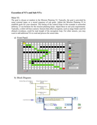
  • 2. Execution of VI’s and Sub-VI’s: Main VI: The goal is chosen at random in the Mission Planning VI. Typically, the goal is provided by some external input, or a stored sequence of sub goals. Adjust the Mission Planning VI to establish goals for your situation. The timing of the control loops in this example is somewhat arbitrary. (5 sec/iteration for the mission planning loop). Adjust these to suit your requirements. Typically, a robot will have sensors. Sensors that affect navigation, such as range finder used for obstacle avoidance, could be read insight of the navigation loop. For other sensors, you may want to add additional Vis to read and process the sensor data. a) Front Panel: b) Block Diagram:
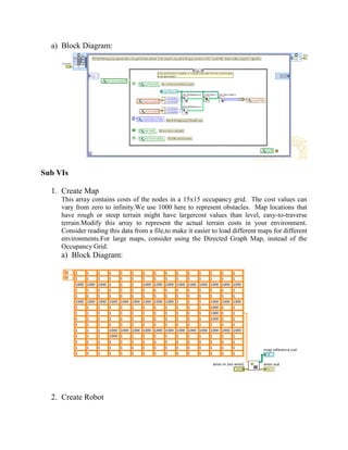
  • 3. 1. Mission Planning Loop The Mission Planning Loop establishes the "goal" of the robot. In this, we randomly compute a new goal whenever we've reached the last goal. This loop could be modified to iterate through a sequence of goals and use them as intermediate steps towards a larger goal. a) Block Diagram: 2. Navigation Loop The Navigation Loop drives the robot to the goal, using the steering API. We might extend this VI by reading sensors to gather data for an obstacle avoidance algorithm. Thiscould be done by reading the sensor data within this loop, or by creating another loop for sensorinputs. a) Block Diagram: 3. Path Planning Loop The Path Planning Loop uses a search algorithm to compute a path from the current robot locationto the goal location, whenever a new goal is selected.If you add obstacle avoidance to the Navigation Loop, you might consider extending this VI torecomputed a new path if the current one becomes untenable.
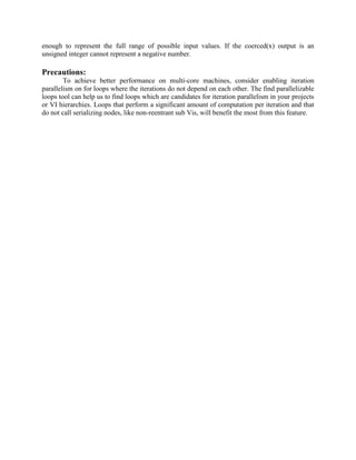
  • 4. a) Block Diagram: Sub VIs 1. Create Map This array contains costs of the nodes in a 15x15 occupancy grid. The cost values can vary from zero to infinity.We use 1000 here to represent obstacles. Map locations that have rough or steep terrain might have largercost values than level, easy-to-traverse terrain.Modify this array to represent the actual terrain costs in your environment. Consider reading this data from a file,to make it easier to load different maps for different environments.For large maps, consider using the Directed Graph Map, instead of the Occupancy Grid. a) Block Diagram: 2. Create Robot
  • 5. This VI creates a simple differential-steering framewith the steering API. This frame will be used inthe Navigation Loop. a) Block Diagram: 3. Draw a Robot Map This VI creates a2D array of colorcontrols, to showthe map of obstacles,goal, and path. a) Front Panel: b) Block Diagram: 4. Initialize map & variable
  • 6. This VI initializes the various shared variables that areused for communications amongthe loops running inparallel. As part of this initialization, we create a map withsome obstacles, and choose an initial starting point andgoal location. a) Block Diagram: 5. Shared Variable Helper 6. Steer Robot:
  • 7. On an actual robot, you would use the Steering VIs to command the motorsto turn and drive the robot appropriately. In this example, we just update thecurrent location along the path. a) Front Panel: b) Block Diagram: Result: In this experiment we implement the trajectory path of a robot using parallel loop algorithm. Here we use loops, three loops of them is mission planning loop, path planning and navigation loop. There three loops are merged in merged function. Merges error I/O clusters from different functions. This function looks for errors beginning with the error in zero parameter and reports the first error found. If the function founds no errors, it looks for warnings and returns the first warning found. If the function founds no warning, it returns no errors. Use exception control to treat what is normally an error as no error or to treat a warning as an error. There have another loop named timed loop. In timed loop, executes one or more sub diagrams, or frames, sequentially each iteration of the loop at the period you specify. Use the timed loop when you want to developVIs with multi range timing capabilities, precise timing, feedback on
  • 8. loop execution, timing characteristics that change dynamically, or several levels of execution priority in mission planning loop we randomly compute a new goal whenever we have reached the last goal. The goal is provided by some external input, or a stored sequence of sub goals. Adjust the mission planning VI to establish goals for your situation. This loop could be modified to iterate though a sequence of goals and use them as intermediate steps towards a larger goal. The navigation loop drives the robot to the goal, using the steering API (Simulated in this example). We might extend this VI by reading sensors to gather data for an obstacle avoidance algorithm. This could be done by reading the sensor data within this loop, or by creating another loop for sensor inputs. And the path planning loop uses a search algorithm to compute a path from the current robot location to planning loop uses a search algorithm to compute a path from the current robot location to the goal location, whenever a new goal is selected. If you add obstacle avoidance to the navigation loop, you might consider extending this VI to re-compute a new path if the current one becomes untenable. Executes one or more sub diagrams, or frames, sequentially each iteration of the loop at the period we specify. Use the timed loop when we want to develop Vis with multi rate timing capabilities, precise timing, feedback on loop execution, timing characteristics that change dynamically, or several levels of execution priority. Create a static map with fixed obstacles for this experiment. Here an array contains costs of the nodes in a 15x15 occupancy grid. The cost values can vary from zero to infinity. We use 1000 here to represents obstacles. Map locations that have rough or steep terrain might have larger cost values than level, easy to traverse terrain. Modify this array to represent the actual terrain costs in your environment. Consider reading this data from a file, to make it easier to load different maps for different environments. For large maps, consider using the directed graph map, instead of the occupancy grid. In initialize map and variables initializes the various shared variables that are used for communications among the loops running in parallel. As part of this initialization, we created a map with some obstacles and choose an initial starting point and goal location. When we drag a shared variable from the project explorer window to the block diagram or placed a shared variable, you can set the node to obsolete or target relative.An obsolete shared variable node always connects to the shared variable on the target on which you created the shared variable. A target relative shared variable node always connects to the shared variable on the target on which you run the VI that contains the shared variable node. On an actual robot, you would use the steering Vis to command the motors to turn and drive the robot appropriately. In this example, we just update the current location along the path. In steer robot function, there have a function named ‘Range and Coerce Function’ which is used for steer the robot. This function compares the input data values according to the Boolean comparison rules. If the function is in compare aggregates mode, it returns the unchanged value of x in coerced(x) rather than a coerced value. The function considers each input array as a single aggregate object, similar to a cluster, where the first element is primary in the comparison. If x is greater than upper limit and the function is in compare elements mode (default), the function coerces x to the upper limit value. If x is less than lower limit and the function is in compare elements mode, the function coerces x to the lower limit value. In the case of numeric values, the upper limit, the lower limit, and x inputs do not have to be the same data type representation. If you wire a combination of signed and unsigned integers to the upper limit, x, and lower limit inputs of the In Range and Coerce function, the data type of the coerced(x) output must be large
  • 9. enough to represent the full range of possible input values. If the coerced(x) output is an unsigned integer cannot represent a negative number. Precautions: To achieve better performance on multi-core machines, consider enabling iteration parallelism on for loops where the iterations do not depend on each other. The find parallelizable loops tool can help us to find loops which are candidates for iteration parallelism in your projects or VI hierarchies. Loops that perform a significant amount of computation per iteration and that do not call serializing nodes, like non-reentrant sub Vis, will benefit the most from this feature.