


EC8551 COMMUNICATION NETWORKS
- 1. KARPAGAM INSTITUTE OF TECHNOLOGY, COIMBATORE - 105 Course Code with Name : EC8551 COMMUNICATION NETWORKS Staff Name / Designation : Dr. M.S.Gowtham /AP Department :ECE Year / Semester :III/05 Department of ECE Karpagam Institute of Technology 1
- 2. COURSE SYLLABUS EC8551 COMMUNICATION NETWORKS L T P C 3 0 0 3 UNIT I FUNDAMENTALS & LINK LAYER 9 Overview of Data Communications- Networks – Building Network and its types– Overview of Internet - Protocol Layering - OSI Mode – Physical Layer – Overview of Data and Signals - introduction to Data Link Layer - Link layer Addressing- Error Detection and Correction UNIT II MEDIA ACCESS & INTERNETWORKING 9 Overview of Data link Control and Media access control - Ethernet (802.3) - Wireless LANs – Available Protocols – Bluetooth – Bluetooth Low Energy – WiFi – 6LowPAN–Zigbee - Network layer services – Packet Switching – IPV4 Address – Network layer protocols ( IP, ICMP, Mobile IP) UNIT III ROUTING Routing - Unicast Routing – Algorithms – Protocols – Multicast Routing and its basics – Overview of Intradomain and interdomain protocols – Overview of IPv6 Addressing – Transition from IPv4 to IPv6 UNIT IV TRANSPORT LAYER 9 Introduction to Transport layer –Protocols- User Datagram Protocols (UDP) and Transmission Control Protocols (TCP) – Services – Features – TCP Connection – State Transition Diagram – Flow, Error and Congestion Control - Congestion avoidance (DECbit, RED) – QoS – Application requirements UNIT V APPLICATION LAYER 9 Application Layer Paradigms – Client Server Programming – World Wide Web and HTTP - DNS- Electronic Mail (SMTP, POP3, IMAP, MIME) – Introduction to Peer to Peer Networks – Need for Cryptography and Network Security – Firewalls. TOTAL: 45 PERIODS Karpagam Institute of Technology 2
- 3. COURSE OBJECTIVES • The student should be made: • Understand the division of network functionalities into layers • Be familiar with the components required to build different types of networks • Be exposed to the required functionality at each layer • Learn the flow control and congestion control algorithms • COURSE OUTCOMES (COs) • Upon completion of the course, the students should be able to: • Identify the components required to build different types of networks • Choose the required functionality at each layer for given application • Identify solution for each functionality at each layer • Trace the flow of information from one node to another node in the network 3Karpagam Institute of Technology
- 4. PROGRAM SPECIFIC OUTCOMES 1. To analyze, design and develop solutions by applying foundational concepts of electronics and communication engineering. 2. To apply design principles and best practices for developing quality products for scientific and business applications. 3. To adapt to emerging information and communication technologies (ICT) to innovate ideas and solutions to existing/novel problems Karpagam Institute of Technology 4
- 5. COURSE OUTCOME Vs. PROGRAM OUTCOMES AND PROGRAM SPECIFIC OUTCOMES MAPPING Karpagam Institute of Technology 5 Course Outcomes PO1 PO2 PO3 PO4 PO5 PO6 PO7 PO8 PO9 PO10 PO11 PO12 PSO2 PSO2 PSO3 C504.1 3 3 3 3 3 3 - - - - 2 2 3 3 3 C504.2 3 3 3 3 3 3 - - - - 2 1 3 3 3 C504.3 3 3 3 3 3 2 - - - - 1 1 3 3 3 C504.4 3 3 3 3 3 2 - - - - 2 2 3 3 3 C504.5 3 3 3 3 3 3 - - - - 2 2 3 3 3
- 6. UNIT 1 FUNDAMENTALS AND LINK LAYER Karpagam Institute of Technology 6
- 7. Definition A communication Network is a collection of methods that users employ to pass on valuable information. The communication network is the sum of all the means and methods that an organization employs to communicate. Applications • Most people know about the Internet (a computer network) through applications • World Wide Web,Email,Online Social Network,Streaming Audio Video,File Sharing,Instant Messaging 7 Karpagam Institute of Technology
- 8. Application Protocol • URL: Uniform resource locater • HTTP: Hyper Text Transfer Protocol • TCP: Transmission Control Protocol • 17 messages for one URLrequest • 6 to find the IP (Internet Protocol) address • 3 for connection establishment of TCP • 4 for HTTP request and acknowledgement • Request: I got your request and I will send the data • Reply: Here is the data you requested; I got the data • 4 messages for tearing down TCP connection 8 Karpagam Institute of Technology
- 9. Requirements • Application Programmer • List the services that his application needs: delay bounded delivery of data • Network Designer • Design a cost-effective network with sharable resources • Network Provider • List the characteristics of a system that is easy to manage 9 Karpagam Institute of Technology
- 10. Connectivity Need to understand the following terminologies Scale Link Nodes Point-to-point Multiple access Switched Network Circuit Switched Packet Switched Packet, message Store-and-forward (a) Point-to-point (b) Multiple access 10 Karpagam Institute of Technology
- 11. Connectivity Terminologies (contd.) Cloud Hosts Switches internetwork Router/gateway Host-to-host connectivity Address Routing Unicast/broadcast/multicast(a) A switchednetwork (b) Interconnection of networks (a) (b) 11 Karpagam Institute of Technology
- 12. Cost-Effective Resource Sharing Resource: links and nodes How to share a link? Multiplexing De-multiplexing Synchronous Time- division Multiplexing Time transmitted slots/data in predetermined slots Multiplexing multiple logicalflows over a single physical link 12 Karpagam Institute of Technology
- 13. Cost-Effective Resource Sharing FDM: Frequency Division Multiplexing Statistical Multiplexing Data is transmitted based on demand of each flow. What is a flow? Packets vs. Messages FIFO, Round-Robin, Priorities (Quality-of- Service (QoS)) Congested? LAN, MAN, WAN SAN (System Area Networks A switch multiplexing packetsfrom multiple sources onto one shared link 13 Karpagam Institute of Technology
- 14. Support for Common Services Logical Channels Application-to-Application communication path or a pipe Process communicating over an abstractchannel 14 Karpagam Institute of Technology
- 15. Common Communication Patterns • Client/Server • Two types of communication channel 1. Request/Reply Channels 2. Message Stream Channels 15 Karpagam Institute of Technology
- 16. Reliability • Network should hide the errors • Bits are lost • Bit errors (1 to a 0, and vice versa) • Burst errors – several consecutive errors • Packets are lost (Congestion) • Links and Node failures • Messages are delayed • Messages are delivered out-of-order • Third parties eavesdrop 16 Karpagam Institute of Technology
- 17. Network Architecture Example of a layered network system Layered system with alternative abstractions available at a given layer 17 Karpagam Institute of Technology
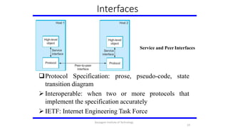
- 18. Protocols Protocol defines the interfaces between the layers in the same system and with the layers of peer system Building blocks of a network architecture Each protocol object has two different interfaces • service interface: operations on this protocol • peer-to-peer interface: messages exchanged with peer Term ―protocol‖ is overloaded • specification of peer-to-peer interface • module that implements this interface 18 Karpagam Institute of Technology
- 19. Interfaces Service and Peer Interfaces Protocol Specification: prose, pseudo-code, state transition diagram 19 Interoperable: when two or more protocols implement the specification accurately IETF: Internet Engineering Task Force that Karpagam Institute of Technology
- 20. Protocol Graph Example of a protocol graph nodes are the protocols and links the ―depends-on‖ relation 20 Karpagam Institute of Technology
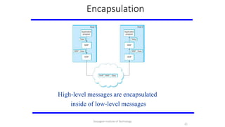
- 21. Encapsulation High-level messages are encapsulated inside of low-level messages 21 Karpagam Institute of Technology
- 22. OSIArchitecture The OSI 7-layer Model OSI – Open Systems Interconnection 22 Karpagam Institute of Technology
- 23. Description of Layers Physical Layer Handles the transmission of raw bits over a communication link Data Link Layer Collects a stream of bits into a larger aggregate called a frame Network adaptor along with device driver in OS implement the protocol in this layer Frames are actually delivered to hosts Network Layer Handles routing among nodes within a packet-switched network Unit of data exchanged between nodes in this layer is calleda packet The lower three layers are implemented on all network nodes 23 Karpagam Institute of Technology
- 24. Description of Layers Transport Layer Implements a process-to-process channel Unit of data exchanges in this layer is called a message Session Layer Provides a name space that is used to tie together the potentially different transport streams that are part of a single application Presentation Layer Concerned about the format of data exchanged between peers Application Layer Standardize common type of exchanges The transport layer and the higher layers typically run onlyon end-hosts and not on the intermediate switches and routers 24 Karpagam Institute of Technology
- 25. InternetArchitecture Internet Protocol Graph Alternative view of the Internet architecture.The ―Network‖ layer shown here is sometimes referred to as the ―sub-network‖ or ―link‖layer. 25 Karpagam Institute of Technology
- 26. InternetArchitecture Defined by IETF Three main features 1. Does not imply strict layering. The application is free to bypass the defined transport layers and to directly use IP or other underlying networks 2. An hour-glass shape – wide at the top, narrow in the middle and wide at the bottom. IP serves as the focal point for the architecture 3. In order for a new protocol to be officially included in the architecture, there needs to be both a protocol specification and at least one (and preferably two) representative implementations of the specification 26 Karpagam Institute of Technology
- 27. Application Programming Interface Interface exported by the network Since most network protocols are implemented (those in the high protocol stack) in software and nearly all computer systems implement their network protocols as part of the operating system, when we refer to the interface ―exported by the network‖, we are generally referring to the interface that the OS provides to its networking subsystem The interface is called the network Application Programming Interface (API) 27 Karpagam Institute of Technology
- 28. Application Programming Interface (Sockets) Socket Interface was originally provided by the Berkeley distribution of Unix Now supported in virtually all operating systems Each protocol provides a certain set of services, and the API provides a syntax by which those services can be invoked in this particular OS 28 Karpagam Institute of Technology
- 29. Socket What is a socket? The point where a local application process attaches to the network An interface between an application and the network An application creates the socket The interface defines operations for Creating a socket Attaching a socket to the network Sending and receiving messages through the socket Closing the socket 29 Karpagam Institute of Technology
- 30. Socket Socket Family PF_INET denotes the Internet family PF_UNIX denotes the Unix pipe facility PF_PACKET denotes direct access to the network interface (i.e., it bypasses the TCP/IP protocol stack) Socket Type SOCK_STREAM is used to denote a byte stream SOCK_DGRAM is an alternative that denotes a message oriented service, such as that provided by UDP 30 Karpagam Institute of Technology
- 31. Creating a Socket int sockfd = socket(address_family, type, protocol); The socket number returned is the socket descriptor for the newly created socket int sockfd = socket (PF_INET,SOCK_STREAM, 0); int sockfd = socket (PF_INET, SOCK_DGRAM, 0); The combination of PF_INET and SOCK_STREAM implies TCP 31 Karpagam Institute of Technology
- 32. Client Server Model with TCP Server Passive open Prepares to accept connection, does not actually establish a connection Server invokes int bind(int socket,struct sockaddr *address, int addr_len) int listen (int socket, int backlog) int accept(int socket,struct sockaddr *address,int *addr_len) 32 Karpagam Institute of Technology
- 33. Client Server Model with TCP Bind Binds the newly created socket to the specified address i.e. the network address of the local participant (the server) Address is a data structure which combines IP and port Listen Defines how many connections can be pending on the specified socket Accept Carries out the passive open Blocking operation Does not return until a remote participant has established a connection When it does, it returns a new socket that corresponds to the new established connection and the address argument contains the remote participant’s address 33 Karpagam Institute of Technology
- 34. Client Server Model with TCP Client Application performs active open It says who it wants to communicate with Client invokes int connect(int socket,struct sockaddr *address,int addr_len) Connect Does not return until TCP has successfully established a connection at which application is free to begin sending data Address contains remote machine’s address 34 Karpagam Institute of Technology
- 35. Client Server Model with TCP In practice The client usually specifies only remote participant’s address and let’s the system fill in the local information Whereas a server usually listens for messages on a well-known port A client does not care which port it uses for itself, the OSsimply selects an unused one Once a connection is established, the application process invokes two operation int send (int socket, char *msg, int msg_len, int flags); int recv (int socket, char *buff, int buff_len, int flags); 35 Karpagam Institute of Technology
- 36. Performanc e Bandwidth Width of the frequency band Number of bits per second that can be transmitted over a communication link 1 Mbps: 1 x 106 bits/second = 1x220 bits/sec 1 x 10⁻⁶ seconds to transmit each bit or imagine that a timeline, now each bit occupies 1 micro second space. On a 2 Mbps link the width is 0.5 micro second. Smaller the width more will be transmission per unit time. 36 Karpagam Institute of Technology
- 37. Bandwidth Bits transmitted at a particular bandwidth can be regarded as having some width: (a) bits transmitted at 1Mbps (each bit 1 μs wide); (b) bits transmitted at 2Mbps (each bit 0.5 μs wide). 37 Karpagam Institute of Technology
- 38. Performance • Latency = Propagation + transmit + queue • Propagation = distance/speed of light • Transmit = size/bandwidth • One bit transmission => propagation is important • Large bytes transmission => bandwidth is important 38 Karpagam Institute of Technology
- 39. Delay X Bandwidth We think the channel between a pair of processes as a hollow pipe Latency (delay) length of the pipe and bandwidth the width of the pipe Delay of 50 ms and bandwidth of 45 Mbps 50 x 10-3 seconds x 45 x 106 bits/second 2.25 x 106 bits = 280 KB data. Network as a pipe Relative importance of bandwidth and latency depends on application For large file transfer, bandwidth is critical For small messages (HTTP, NFS, etc.), latency is critical Variance in latency (jitter) can also affect some applications (e.g., audio/video conferencing) 39 Karpagam Institute of Technology
- 40. Delay X Bandwidth How many bits the sender must transmit before the first bit arrives at the receiver if the sender keeps the pipe full Takes another one-way latency to receive a response from the receiver If the sender does not fill the pipe—send a whole delay bandwidth product’s worth of data before it stops to wait for a signal—the sender will not fully utilize the network Infinite bandwidth RTT dominates Throughput = TransferSize / TransferTime TransferTime = RTT + 1/Bandwidth x TransferSize Its all relative 1-MB file to 1-Gbps link looks like a 1-KB packet to 1-Mbps link 40 Karpagam Institute of Technology
- 41. Relationship bet. bandwidth & latency A 1-MB file would fill the 1-Mbps link 80 times, but only fill the 1-Gbpslink 1/12 of one time 41 Karpagam Institute of Technology
- 42. Link layer Services 42 Karpagam Institute of Technology
- 43. Perspectives on Connecting An end-user’s view of the Internet 43 Karpagam Institute of Technology
- 44. Link Capacity & Shannon-Hartley Theorem Gives the upper bound to the capacity of a link in terms of bits per second (bps) as a function of signal-to-noise ratio of the link measured in decibels (dB). C = Blog2(1+S/N) Where B = 3300 – 300 = 3000Hz, S is the signal power, N the average noise. The signal to noise ratio (S/N) is measured in decibels is related to dB = 10 x log10(S/N). If there is 30dB of noise then S/N = 1000. Now C = 3000 x log2(1001) = 30kbps. How can we get 56kbps? 44 Karpagam Institute of Technology
- 45. Links All practical links rely on some sort of electromagnetic radiation propagating through a medium or, in some cases, through free space One way to characterize links, then, is by the medium they use Typically copper wire in some form (as in Digital Subscriber Line (DSL) and coaxial cable), Optical fiber (as in both commercial fiber-to-the home services and many long-distance links in the Internet’s backbone), or Air/free space (for wireless links) Another important link characteristic is the frequency Measured in hertz, with which the electromagnetic waves oscillate 45 Karpagam Institute of Technology
- 46. Links Distance between the adjacent pair of maxima or minima of a wave measured in meters is called wavelength Speed of light divided by frequency gives the wavelength. Frequency on a copper cable range from 300Hz to 3300Hz; Wavelength for 300Hz wave through copper is speed of light on a copper /frequency 2/3 x 3 x 108 /300 = 667 x 103meters. Electromagnetic spectrum 46 Karpagam Institute of Technology
- 47. Links Common services available to connect yourhome Placing binary data on a signal is called encoding. Modulation involves modifying the signals in terms of their frequency, amplitude, and phase. 47 Karpagam Institute of Technology
- 48. Encoding Signals travel between signaling components; bits flow between adaptors NRZ encoding of a bit stream 48 Karpagam Institute of Technology
- 49. Encoding Problem with NRZ Baseline wander The receiver keeps an average of the signals it has seen so far Uses the average to distinguish between low and high signal When a signal is significantly low than the average, it is 0, else it is1 Too many consecutive 0’s and 1’s cause this average to change, making it difficult to detect Clock recovery Frequent transition from high to low or vice versa are necessary toenable clock recovery Both the sending and decoding process is driven by a clock Every clock cycle, the sender transmits a bit and the receiver recovers a bit The sender and receiver have to be precisely synchronized 49 Karpagam Institute of Technology
- 50. Encoding NRZI Non Return to Zero Inverted Sender makes a transition from the current signal to encode 1 and stay at the current signal to encode 0 Solves for consecutive 1’s Manchester encoding Merging the clock with signal by transmitting Ex-OR of the NRZ encoded data and the clock Clock is an internal signal that alternates from low to high, a low/high pair is considered as one clock cycle In Manchester encoding 0: low high transition 1: high low transition 5 0 Karpagam Institute of Technology
- 51. Encoding Different encoding strategies 51 Karpagam Institute of Technology
- 52. Encoding Problem with Manchester encoding Doubles the rate at which the signal transitions are made on thelink Which means the receiver has half of the time to detect each pulse of the signal The rate at which the signal changes is called the link’s baud rate In Manchester the bit rate is half the baud rate 4B/5B encoding Insert extra bits into bit stream so as to break up the long sequence of 0’s and 1’s Every 4-bits of actual data are encoded in a 5- bit code that is transmitted to the receiver 5-bit codes are selected in such a way that each one has no more than one leading 0(zero) and no more than two trailing0’s. No pair of 5-bit codes results in more than three consecutive0’s 52 Karpagam Institute of Technology
- 53. Encoding 4B/5B encoding • 0000 11110 • 0001 01001 • 0010 10100 • .. • .. • 1111 11101 16 left 11111 – when the line is idle 00000 – when the line is dead 00100 – to mean halt 13 left : 7 invalid, 6 for various control signals 53 Karpagam Institute of Technology
- 54. Framing We are focusing on packet-switched networks, which means that blocks of data (called frames at this level), not bit streams, are exchanged between nodes. It is the network adaptor that enables the nodes to exchange frames. When node A wishes to transmit a frame to node B, it tells its adaptor to transmit a frame from the node’s memory. This results in a sequence of bits being sent over the link. Bits flow between adaptors, frames between hosts 54 Karpagam Institute of Technology
- 55. Framing The adaptor on node B then collects together the sequence of bits arriving on the link and deposits the corresponding frame in B’s memory. Recognizing exactly what set of bits constitute a frame— that is, determining where the frame begins and ends—is the central challenge faced by the adaptor Byte-oriented Protocols To view each frame as a collection of bytes (characters) rather than bits BISYNC (Binary Synchronous Communication) Protocol Developed by IBM (late 1960) DDCMP (Digital Data Communication Protocol) Used in DECNet 55 Karpagam Institute of Technology
- 56. Framing BISYNC – sentinel approach Frames transmitted beginning with leftmost field Beginning of a frame is denoted by sending a special SYN (synchronize) character Data portion of the frame is contained between special sentinel characterSTX (start of text) and ETX (end of text) SOH : Start of Header DLE : Data Link Escape CRC: Cyclic Redund.Check Recent PPP which is commonly run over Internet links uses sentinelapproach Special start of text character denoted as Flag 0 1 1 1 1 1 1 0 Address, control : default numbers Protocol for demux : IP / IPX Payload : negotiated (1500 bytes) Checksum : for error detection 55 5 6 Karpagam Institute of Technology
- 57. Framing Byte-counting approach DDCMP count : how many bytes are contained in the frame body If count is corrupted Framing error Bit-oriented Protocol HDLC : High Level Data Link Control Beginning and Ending Sequences 0 1 1 1 1 1 1 0 On the sending side, any time five consecutive 1’s have been transmitted from the body of the message (i.e. excluding when the sender is trying to send the distinguished 01111110sequence) The sender inserts 0 before transmitting the nextbit 57 Karpagam Institute of Technology
- 58. Framing HDLC Protocol On the receiving side 5 consecutive 1’s Next bit 0 : Stuffed, so discard it 1 : Either End of the frame marker Or Error has been introduced in the bitstream Look at the next bit If 0 ( 01111110 ) End of the frame marker If 1 ( 01111111 ) Error, discard the whole frame The receiver needs to wait for next 01111110 before it can start receiving again 58 Karpagam Institute of Technology
- 59. Error Detection Bit errors are introduced into frames Because of electrical interference and thermal noises Detecting Error and Correction Error Two approaches when the recipient detects an error Notify the sender that the message was corrupted, so the sender can send again. If the error is rare, then the retransmitted message will be error-free Using some error correct detection and correction algorithm, the receiver reconstructs the message Common technique for detecting transmission error CRC (Cyclic Redundancy Check) Used in HDLC, DDCMP, CSMA/CD, Token Ring Other approaches Two Dimensional Parity (BISYNC) Checksum (IP) 55 5 9 Karpagam Institute of Technology
- 60. Error Detection Basic Idea of Error Detection To add redundant information to a frame that can be used to determine if errors have been introduced Imagine (Extreme Case) Transmitting two complete copies of data Identical No error Differ Error Poor Scheme ??? n bit message, n bit redundant information Error can go undetected In general, we can provide strong error detection technique k redundant bits, n bits message, k << n In Ethernet, a frame carrying up to 12,000 bits of data requires only 32-bit CRC 59 5 6 Karpagam Institute of Technology
- 61. Error Detection Extra bits are redundant They add no new information to the message Derived from the original message using some algorithm Both the sender and receiver know the algorithm Sender Receiver Receiver computes r using m If they match, no error m rm r 61 Karpagam Institute of Technology
- 62. Two-dimensional parity Two-dimensional parity is exactly what the name suggests It is based on ―simple‖ (one-dimensional) parity, which usually involves adding one extra bit to a 7-bit code to balance the number of 1s in the byte. For example, Odd parity sets the eighth bit to 1 if needed to give an odd number of 1s in the byte, and Even parity sets the eighth bit to 1 if needed to give an even number of 1s in the byte Two-dimensional parity does a similar calculation for each bit position across each of the bytes contained in the frame 62 Karpagam Institute of Technology
- 63. Two-dimensional parity This results in an extra parity byte for the entire frame, in addition to a parity bit for each byte Two-dimensional parity catches all 1-, 2-, and 3-bit errors and most 4-bit errors 63 Karpagam Institute of Technology
- 64. Internet ChecksumAlgorithm Not used at the link level Add up all the words that are transmitted and then transmit the result of that sum The result is called the checksum The receiver performs the same calculation on the received data and compares the result with the received checksum If any transmitted data, including the checksum itself, is corrupted, then the results will not match, so the receiver knows that an error occurred Consider the data being checksummed as a sequence of 16- bit integers. 64 Karpagam Institute of Technology
- 65. Internet ChecksumAlgorithm Add them together using 16-bit ones complement arithmetic (explained next slide) and then take the ones complement of the result. That 16-bit number is the checksum In ones complement arithmetic, a negative integer −x is represented as the complement of x; Each bit of x is inverted. When adding numbers in ones complement arithmetic, a carryout from the most significant bit needs to be added to the result. 65 Karpagam Institute of Technology
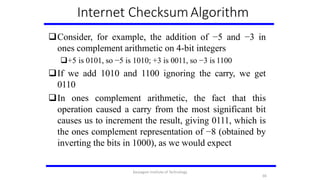
- 66. Internet ChecksumAlgorithm Consider, for example, the addition of −5 and −3 in ones complement arithmetic on 4-bit integers +5 is 0101, so −5 is 1010; +3 is 0011, so −3 is 1100 If we add 1010 and 1100 ignoring the carry, we get 0110 In ones complement arithmetic, the fact that this operation caused a carry from the most significant bit causes us to increment the result, giving 0111, which is the ones complement representation of −8 (obtained by inverting the bits in 1000), as we would expect 66 Karpagam Institute of Technology
- 67. Cyclic Redundancy Check (CRC) Reduce the number of extra bits and maximize protection Given a bit string 110001 we can associate a polynomial on a single variable x for it. 1.x5+1.x4+0.x3+0.x2+0.x1+1.x0 = x5+x4+1 and the degree is5. A k-bit frame has a maximum degree of k-1 Let M(x) be a message polynomial and C(x) be a generator polynomial. Let M(x)/C(x) leave a remainder of 0. When M(x) is sent and M’(x) is received we have M’(x) = M(x)+E(x) The receiver computes M’(x)/C(x) and if the remainder is nonzero, then an error has occurred. The only thing the sender and the receiver should know is C(x). 67 6 7 Karpagam Institute of Technology
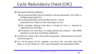
- 68. Cyclic Redundancy Check (CRC) Polynomial Arithmetic Modulo2 Any polynomial B(x) can be divided by a divisor polynomial C(x) if B(x) is of higher degree than C(x). Any polynomial B(x) can be divided once by a divisor polynomial C(x) if B(x) is of the same degree as C(x). The remainder obtained when B(x) is divided by C(x) is obtained by subtracting C(x) from B(x). To subtract C(x) from B(x), we simply perform the exclusive- OR (XOR) operation on each pair of matching coefficients. Let M(x) be a frame with m bits and let the generator polynomial have less than m bits say equal to r. Let r be the degree of C(x). Append r zero bits to the low-order end of the frame, so it now contains m+r bits and corresponds to the polynomial xrM(x). 68 6 8 Karpagam Institute of Technology
- 69. Cyclic Redundancy Check (CRC) Divide the bit string corresponding to xrM(x) by the bit s corresponding to C(x) using modulo 2 division. Subtract the remainder (which is always r or fewer bits) from xrM(x) using modulo subtraction (addition the string corresponding to 2 and subtraction are the same in modulo 2). The result checksummed transmitted. Call is the frame to be it polynomial M’(x). CRC Calculation using Polynomial Long Division 656 9 Karpagam Institute of Technology
- 70. Cyclic Redundancy Check (CRC) Properties of Generator Polynomial Let P(x) represent what the sender sent and P(x) + E(x) is the received string. A 1 in E(x) represents that in the corresponding position in P(x) the message the bit is flipped. We know that P(x)/C(x) leaves a remainder of 0, but if E(x)/C(x) leaves a remainder of 0, then either E(x) = 0 or C(x) is factor ofE(x). When C(x) is a factor of E(x) we have problem; errors gounnoticed. If there is a single bit error then E(x) = xi, where i determines the bit in error. If C(x) contains two or more terms it will never divide E(x), so all single bit errors will be detected. In general, it is possible to prove that the following types of errors can be detected by a C(x) with the stated properties All single-bit errors, as long as the xk and x0 terms have nonzerocoefficients. All double-bit errors, as long as C(x) has a factor with at least threeterms. Any odd number of errors, as long as C(x) contains the factor(x+1). Any ―burst‖error (i.e., sequence of consecutive error bits) for which the length of the burst is less than k bits. (Most burst errors of larger than k bits can also 69 7 0 Karpagam Institute of Technology
- 71. Cyclic Redundancy Check (CRC) Six generator polynomials that have become international standards are: CRC-8 = x8+x2+x+1 CRC-10 = x10+x9+x5+x4+x+1 CRC-12 = x12+x11+x3+x2+x+1 CRC-16 = x16+x15+x2+1 CRC-CCITT = x16+x12+x5+1 CRC-32 = x32+x26+x23+x22+x16+x12+x11+x10+x8+x7+x5+x4+x2+x+1 71 Karpagam Institute of Technology
- 72. Reliable Transmission CRC is used to detect errors. Some error codes are strong enough to correct errors. The overhead is typically too high. Corrupt frames must be discarded. A link-level protocol that wants to deliver frames reliably must recover from these discarded frames. This is accomplished using a combination of two fundamental mechanisms Acknowledgements and Timeouts An acknowledgement (ACK for short) is a small control frame that a protocol sends back to its peer saying that it has received the earlier frame. A control frame is a frame with header only (no data). 72 Karpagam Institute of Technology
- 73. Reliable Transmission The receipt of an acknowledgement indicates to the sender of the original frame that its frame was successfully delivered. If the sender does not receive an acknowledgment after a reasonable amount of time, then it retransmits the original frame. The action of waiting a reasonable amount of time is called a timeout. The general strategy of using acknowledgements and timeouts to implement reliable delivery is sometimes called Automatic Repeat reQuest (ARQ). 73 Karpagam Institute of Technology
- 74. Stop and Wait Protocol Idea of stop-and-wait protocol is straightforward After transmitting one frame, the sender waits for an acknowledgement before transmitting the next frame. If the acknowledgement does not arrive after a certain period of time, the sender times out and retransmits the original frame Timeline showing four different scenarios for the stop- and-wait algorithm. (a) The ACK is received before the timer expires; (b) the original frame is lost; (c) the ACK is lost; (d) the timeout fires too soon 7 4 Karpagam Institute of Technology
- 75. Stop and Wait Protocol If the acknowledgment is lost or delayed in arriving The sender times out and retransmits the original frame, but the receiver will think that it is the next frame since it has correctly received and acknowledged the first frame As a result, duplicate copies of frames will be delivered How to solve this Use 1 bit sequence number (0 or 1) When the sender retransmits frame 0, the receiver can determine that it is seeing a second copy of frame 0 rather than the first copy of frame 1 and therefore can ignore it (the receiver still acknowledges it, in case the first acknowledgement was lost) Timeline for stop-and-wait with 1-bit sequence number 75 Karpagam Institute of Technology
- 76. Stop and Wait Protocol The sender has only one outstanding frame on the link at a time This may be far below the link’s capacity Consider a 1.5 Mbps link with a 45 ms RTT The link has a delay bandwidth product of 67.5 Kb or approximately 8 KB Since the sender can send only one frame per RTT and assuming a frame size of 1 KB Maximum Sending rate Bits per frame Time per frame = 1024 8 0.045 = 182 Kbps Or about one-eighth of the link’s capacity To use the link fully, then sender should transmit up to eight frames before having to wait for an acknowledgement 76 Karpagam Institute of Technology
- 77. Sliding Window Protocol Timeline for Sliding Window Protocol Sender assigns a sequence number denoted as SeqNum to each frame. Assume it can grow infinitely large Sender maintains three variables Sending Window Size (SWS) Upper bound on the number of outstanding (unacknowledged) frames that the sender can transmit Last AcknowledgementReceived (LAR) Sequence number of the last 77 acknowledgement received Last Frame Sent (LFS) Sequence number of the last frame sent Karpagam Institute of Technology
- 78. Sliding Window Protocol Sender also maintains the following invariant LFS – LAR ≤ SWS Sliding Window on Sender When an acknowledgement arrives the sender moves LAR to right, thereby allowing the sender to transmit another frame Also the sender associates a timer with each frame it transmits It retransmits the frame if the timer expires before the ACK isreceived Note that the sender has to be willing to buffer up to SWS frames WHY? 78 Karpagam Institute of Technology
- 79. Sliding Window Protocol Receiver maintains three variables Receiving Window Size (RWS) Upper bound on the number of out-of-order frames that the receiver is willing to accept Largest Acceptable Frame (LAF) Sequence number of the largest acceptable frame Last Frame Received (LFR) Sequence number of the last frame received Receiver also maintains the following invariant LAF – LFR ≤ RWS Sliding Window on Receiver 79 Karpagam Institute of Technology
- 80. Sliding Window Protocol When a frame with sequence number SeqNum arrives, what does the receiver do? If SeqNum ≤ LFR or SeqNum > LAF Discard it (the frame is outside the receiver window) If LFR < SeqNum ≤ LAF Accept it Now the receiver needs to decide whether or not to send anACK Let SeqNumToAck Denote the largest sequence number not yet acknowledged, such that all frames with sequence number less than or equal to SeqNumToAck have been received The receiver acknowledges the receipt of SeqNumToAck even if high- numbered packets have been received This acknowledgement is said to be cumulative. The receiver then sets LFR = SeqNumToAck and adjusts LAF = LFR + RWS 8 0 Karpagam Institute of Technology
- 81. Issues with Sliding Window Protocol When timeout occurs, the amount of data in transit decreases Since the sender is unable to advance its window When the packet loss occurs, this scheme is no longer keeping the pipe full The longer it takes to notice that a packet loss has occurred, the more severe the problem becomes How to improve this Negative Acknowledgement(NAK) AdditionalAcknowledgement SelectiveAcknowledgement Negative Acknowledgement (NAK) Receiver sends NAK for frame 6 when frame 7 arrive (in the previous example) However this is unnecessary since sender’s timeout mechanism will be sufficient to catch the situation AdditionalAcknowledgement Receiver sends additional ACK for frame 5 when frame 7 arrives Sender uses duplicate ACK as a clue for frame loss 8 1 Karpagam Institute of Technology
- 82. References • TEXT BOOK: • T1: Behrouz A. Forouzan, ―“Data communication and Networking”, Fifth Edition, Tata McGraw – Hill, 2013 (UNIT I –V) • REFERENCES: • R1 James F. Kurose, Keith W. Ross, “Computer Networking - A Top-Down Approach Featuring the Internet”, • seventh Edition, Pearson Education, 2016. • R2 Nader. F. Mir, “Computer and Communication Networks”, Pearson Prentice Hall Publishers, 2nd Edition, 2014. • R3 Ying-Dar Lin, Ren-Hung Hwang, Fred Baker, “Computer Networks: An Open Source Approach”, Mc Graw Hill • Publisher, 2011. • R4 Larry L. Peterson, Bruce S. Davie, “Computer Networks: A Systems Approach”, Fifth Edition, Morgan Kaufmann • Publishers, 2011. 8 2 Karpagam Institute of Technology
- 83. SUMMARY • The data link layer is the protocol layer in a program that handles the moving of data into and out of a physical link in a network. • Data bits are encoded, decoded and organized in the data link layer, before they are transported as frames between two adjacent nodes on the same LAN or WAN Karpagam Institute of Technology 83
- 84. ASSIGNMENT QUESTIONS S.No. Topic K Level 1. Analyze the cyclic codes to find its capabilities by using polynomials. K3 2. Evaluate the following: (i) Hardware Implementation of Cyclic codes (ii) Checksum K2 8 4 Karpagam Institute of Technology
- 85. Video Tutorials S.No. Topic LINK 1. Network Protocol Layers https://www.youtube.com/ watch?v=_9QayISruzo 2 Error Detection and Correction https://www.youtube.com/ watch?v=aNqiTCZ-nko 8 5 Karpagam Institute of Technology
- 86. QUIZ QUESTIONS1.Several computers linked to a server to share programs and storage space. A. Library B. Network C. Grouping D. Integrated system 2.Which of the following device is used to connect two systems, especially if the systems use different protocols? A. Repeater B. Gateway C. Bridge D. Hub 3.The collection of links throughout the Internet creates an interconnected network called the A. WWW B. Web 8 6 Karpagam Institute of Technology
- 87. 4.Network architecture has a stack of layers. Which of the following is not true for this architecture? A. Different layers can be developed separately B. Layers internals are independent C. Network protocols cannot work with multiple layers D. A device can handle one or more layers as per requirement 5.Who defines the Internet architecture? A. IETF B. IEEE C. ACM D. None 6.What are the end network devices? A. Servers, smartphones and computers B. Transceivers, NICs C. Routers and servers D. Smartphones, cell towers 8 7 Karpagam Institute of Technology
- 88. 7.P2P is a _____ application architecture. A. Client/server B. Distributed C. Centralized D. 1-tier 8._______ is the most important/powerful computer in a typical network. A. Desktop B. Network server C. Network client D. Network switch 9. IP is responsible for packet switching True B. False 10. OSI Model consists of _______layers A.5 B.7 C.9 D.6 8 8 Karpagam Institute of Technology
- 89. 11. Which network topology requires a central controller or hub? a) Star b) Mesh c) Ring d) Bus Answer: a 12. Data communication system spanning states, countries, or the whole world is ________ a) LAN b) WAN c) MAN d) PAN Answer: b 13. _____ is the multiplexing technique that shifts each signal to a different carrier frequency. a) FDM b) TDM c) Both FDM & TDM d) PDM Answer: a 14. Which multiplexing technique used to transmit digital signals? a) FDM b) TDM c) WDM d) FDM & WDM Answer: b 15. Which of the following delay is faced by the packet in travelling from one end system to another? a) Propagation delay b) Queuing delay c) Transmission delay d) All of the mentioned Answer: d Karpagam Institute of Technology 89
- 90. 17. Which of the following is an example of a bounded medium? (A) coaxial cable (B) wave guide (C) fiber optic cable (D) all of these Answer . D 18. LAN can use ________ architecture. A. Client and server B. Peer–to–peer C. Both a and b D. Neither A or B ANS: C 19. Which sublayer of the data link layer performs data link functions that depend upon the type of medium? a) logical link control sublayer b) media access control sublayer c) network interface control sublayer d) error control sublayer Answer: b 20. Transport layer aggregates data from different applications into a single stream before passing it to ____________ a) network layer b) data link layer c) application layer d) physical layer Answer: a Karpagam Institute of Technology 90
- 91. 22.Which of the following transport layer protocolss is used to support electronic mail? (A) SMTP (B) IP (C) TCP (D) UDP Answer :(C) 23. Which address is used to identify a process on a host by the transport layer? a) physical address b) logical address c) port address d) specific address Answer: c 24.Bits can be sent over guided and unguided media as analog signal by ___________ a) digital modulation b) amplitude modulation c) frequency modulation d) phase modulation Answer: a 25.The technique of temporarily delaying outgoing acknowledgements so that they can be hooked onto the next outgoing data frame is called ____________ a) piggybacking b) cyclic redundancy check c) fletcher’s checksum d) parity check Answer: a 26.Multiplexing is used in _______ a) Packet switching b) Circuit switching c) Data switching d) Packet & Circuit switching Answer: b 27.Fiber optics posses following properties __________ a) Immune electromagnetic interference b) Very less signal attenuation c) Very hard to tap d) All of the mentioned Answer: d Karpagam Institute of Technology 91
- 92. 46. What is the benefit of the Networking? A. File Sharing B. Easier access to Resources C. Easier Backups D. All of the Above Answer: D 47. Which of the following is the fastest communication channel? A. Micro wave B. Optical fiber C. Radio wave D. None of the above Answer: A 48. Encryption and decryption are the function of A. Session layer B. Presentation layer C. Transport layer D. None of the above Answer: B 49. An inter–company network which used to distribute information documents files and database is called as A. MAN B. WAN C. LAN D. Switch Answer: C Karpagam Institute of Technology 92
- 93. Unit - II MEDIAACCESS &INTERNETWORKING Karpagam Institute of Technology 93
- 94. Ethernet Most successful local area networking technology of last 20 years. Developed in the mid-1970s by researchers at the Xerox Palo Alto Research Centers (PARC). Uses CSMA/CD technology Carrier Sense Multiple Access with CollisionDetection. A set of nodes send and receive frames over a sharedlink. Carrier sense means that all nodes can distinguish between an idle and a busy link. Collision detection means that a node listens as it transmits and can therefore detect when a frame it is transmitting has collided with a frame transmitted by another node. Uses ALOHA (packet radio network) as the rootprotocol Developed at the University of Hawaii to support communication across the Hawaiian Islands. For ALOHA the medium was atmosphere, for Ethernet the medium is a coax cable. 94 Karpagam Institute of Technology
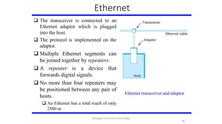
- 95. Ethernet DEC and Intel joined Xerox to define a 10-Mbps Ethernet standard in 1978. This standard formed the basis for IEEE standard 802.3 More recently 802.3 has been extended to include a 100-Mbps version called Fast Ethernet and a 1000-Mbps version called Gigabit Ethernet. An Ethernet segment is implemented on a coaxial cable of up to 500 m. This cable is similar to the type used for cable TV except that it typically has an impedance of 50 ohms instead of cable TV’s 75 ohms. Hosts connect to an Ethernet segment by tapping into it. A transceiver (a small device directly attached to the tap) detects when the line is idle and drives signal when the host is transmitting. The transceiver also receives incoming signal. 95 Karpagam Institute of Technology
- 96. Ethernet The transceiver is connected to an Ethernet adaptor which is plugged into the host. The protocol is implemented on the adaptor. Multiple Ethernet segments can be joined together by repeaters. A repeater is a device that forwards digital signals. No more than four repeaters may be positioned between any pair of hosts. An Ethernet has a total reach of only 2500 m. Ethernet transceiver and adaptor 96 Karpagam Institute of Technology
- 97. Ethernet Ethernet repeater Any signal 97 placed on the host isby a over the entire Ethernet broadcast network Signal is propagated in both directions. Repeaters forward the signal on all outgoing segments. Terminators attached to the end of each segment absorb the signal. Ethernet uses Manchester encoding scheme. Karpagam Institute of Technology
- 98. Ethernet New Technologies in Ethernet Instead of using coax cable, an Ethernet can be constructed from athinner cable known as 10Base2 (the original was 10Base5) 10 means the network operates at 10 Mbps Base means the cable is used in a baseband system 2 means that a given segment can be no longer than 200 m Another cable technology is 10BaseT T stands for twisted pair Limited to 100 m in length With 10BaseT, the common configuration is to have several point to point segments coming out of a multiway repeater, called Hub Ethernet Hub 98 Karpagam Institute of Technology
- 99. Access Protocol for Ethernet The algorithm is commonly called Ethernet’s Media Access Control (MAC). It is implemented in Hardware on the network adaptor. Frame format Preamble (64bit): allows the receiver to synchronize with the signal (sequence of alternating 0s and 1s). Host and Destination Address (48biteach). Packet type (16bit): acts as demux key to identify the higher level protocol. Data (up to 1500 bytes) Minimally a frame must contain at least 46 bytes of data. Frame must be long enough to detect collision. CRC (32bit) 99 Karpagam Institute of Technology
- 100. Ethernet Addresses Each host on an Ethernet (in fact, every Ethernet host in the world) has a unique EthernetAddress. The address belongs to the adaptor, not the host. It is usually burnt into ROM. Ethernet addresses are typically printed in a human readable format As a sequence of six numbers separated by colons. Each number corresponds to 1 byte of the 6 byte address and is given by a pair of hexadecimal digits, one for each of the 4-bit nibbles in thebyte Leading 0s are dropped. For example, 8:0:2b:e4:b1:2 is 00001000 00000000 00101011 11100100 10110001 00000010 To ensure that every adaptor gets a unique address, each manufacturer of Ethernet devices is allocated a different prefix that must be prepended to the address on every adaptor they build AMD has been assigned the 24bit prefix 8:0:20 100 Karpagam Institute of Technology
- 101. Ethernet Addresses Each frame transmitted on an Ethernet is received by every adaptor connected to that Ethernet. Each adaptor recognizes those frames addressed to its address and passes only those frames on to the host. In addition, to unicast address, an Ethernet address consisting of all 1s is treated as a broadcast address. All adaptors pass frames addressed to the broadcast address up to the host. Similarly, an address that has the first bit set to 1 but is not the broadcast address is called a multicast address. A given host can program its adaptor to accept some set of multicast addresses. To summarize, an Ethernet adaptor receives all frames and accepts Frames addressed to its own address Frames addressed to the broadcast address Frames addressed to a multicast addressed if it has been instructed 101 Karpagam Institute of Technology
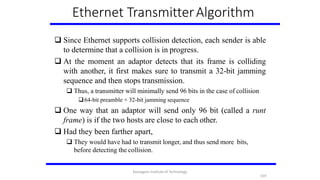
- 102. Ethernet TransmitterAlgorithm When the adaptor has a frame to send and the line is idle, it transmits the frame immediately. The upper bound of 1500 bytes in the message means that the adaptor can occupy the line for a fixed length of time. When the adaptor has a frame to send and the line is busy, it waits for the line to go idle and then transmits immediately. The Ethernet is said to be 1-persistent protocol because an adaptor with a frame to send transmits with probability 1 whenever a busy line goes idle. Since there is no centralized control it is possible for two (or more) adaptors to begin transmitting at the same time, Either because both found the line to be idle, Or, both had been waiting for a busy line to become idle. When this happens, the two (or more) frames are said to be collide on the network. 102 Karpagam Institute of Technology
- 103. Ethernet TransmitterAlgorithm Since Ethernet supports collision detection, each sender is able to determine that a collision is in progress. At the moment an adaptor detects that its frame is colliding with another, it first makes sure to transmit a 32-bit jamming sequence and then stops transmission. Thus, a transmitter will minimally send 96 bits in the case of collision 64-bit preamble + 32-bit jamming sequence One way that an adaptor will send only 96 bit (called a runt frame) is if the two hosts are close to each other. Had they been farther apart, They would have had to transmit longer, and thus send more bits, before detecting the collision. 103 Karpagam Institute of Technology
- 104. Ethernet TransmitterAlgorithm The worst case scenario happens when the two hosts are at opposite ends of the Ethernet. To know for sure that the frame its just sent did not collide with another frame, the transmitter may need to send as many as 512 bits. Every Ethernet frame must be at least 512 bits (64 bytes) long. 14 bytes of header + 46 bytes of data + 4 bytes of CRC Why 512 bits? Why is its length limited to 2500 m? The farther apart two nodes are, the longer it takes for a frame sent by one to reach the other, and the network is vulnerable to collision during this time 104 Karpagam Institute of Technology
- 105. Ethernet TransmitterAlgorithm A begins transmitting a frame at time t d denotes the one link latency The first bit of A’s frame arrives at B at time t + d Suppose an instant before host A’s frame arrives, host B begins to transmit its own frame B’s frame will immediately collide with A’s frame and this collision will be detected by host B Host B will send the 32-bit jamming sequence Host A will not know that the collision occurred until B’s frame reaches it, which will happen at t + 2 * d Host A must continue to transmit until this time in order to detect the collision Host A must transmit for 2 * d to be sure that it detects all possible collisions Worst-case scenario: (a) A sends a frame at time t; (b) A’sframe arrives at B attime t + d; (c) B begins transmitting at time t + d and collides with A’sframe; (d) B’s runt (32-bit) frame arrives at Aat time t + 2d. 14Karpagam Institute of Technology 105
- 106. Ethernet TransmitterAlgorithm Consider that a maximally configured Ethernet is 2500 m long, and there may be up to four repeaters between any two hosts, the round trip delay has been determined to be 51.2 s Which on 10 Mbps Ethernet corresponds to 512 bits The other way to look at this situation, We need to limit the Ethernet’s maximum latency to a fairly small value (51.2 s) for the access algorithm to work Hence the maximum length for the Ethernet is on the order of 2500m. Once an adaptor has detected a collision, and stopped its transmission, it waits a certain amount of time and tries again. Each time the adaptor tries to transmit but fails, it doubles the amount of time it waits before trying again. Karpagam Institute of Technology
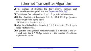
- 107. Ethernet TransmitterAlgorithm This strategy of doubling the delay interval between each retransmission attempt is known as Exponential Backoff. The adaptor first delays either 0 or 51.2 s, selected at random. s (selected If this effort fails, it then waits 0, 51.2, 102.4, 153.6 randomly) before trying again; This is k * 51.2 for k = 0, 1, 2, 3 After the third collision, it waits k * 51.2 for k = 0…23 – 1 (again selected at random). In general, the algorithm randomly selects a k between 0 and 2n – 1 and waits for k * 51.2 s, where n is the number of collisions experienced so far. Karpagam Institute of Technology
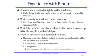
- 108. Experience with Ethernet Ethernets work best under lightly loaded conditions. Under heavy loads, too much of the network’s capacity is wasted by collisions. Most Ethernets are used in a conservative way. Have fewer than 200 hosts connected to them which is far fewer than the maximum of 1024. Most Ethernets are far shorter than 2500m with a round-trip delay of closer to 5 s than 51.2 s. Ethernets are easy to administer and maintain. There are no switches that can fail and no routing and configuration tables that have to be kept up-to-date. It is easy to add a new host to the network. It is inexpensive. Cable is cheap, and only other cost is the network adaptor on each host. Karpagam Institute of Technology
- 109. Wireless Links Wireless links transmit electromagnetic signals Radio, microwave, infrared Wireless links all share the same “wire” (so to speak) The challenge is to share it efficiently without unduly interfering with eachother Most of this sharing is accomplished by dividing the “wire” alongthe dimensions of frequency and space Exclusive use of a particular frequency in a particular geographicarea may be allocated to an individual entity such as a corporation Devices that use license-exempt frequencies are still subject to certain restrictions The first is a limit on transmission power This limits the range of signal, making it less likely to interfere with another signal For example, a cordless phone might have a range of about 100 feet. Karpagam Institute of Technology
- 110. Wireless Links These allocations are determined by government agencies such as FCC (Federal Communications Commission) in USA Specific bands (frequency) ranges are allocated to certain uses. Some bands are reserved for government use Other bands are reserved for uses such as AM radio, FM radio, televisions, satellite communications, and cell phones Specific frequencies within these bands are then allocated to individual organizations for use within certain geographical areas. Finally, there are several frequency bands set aside for “license exempt” usage Bands in which a license is not needed Karpagam Institute of Technology
- 111. Wireless Links The second restriction requires the use of Spread Spectrum technique Idea is to spread the signal over a wider frequency band So as to minimize the impact of interference from other devices Originally designed for military use Frequency hopping Transmitting signal over a random sequence of frequencies First transmitting at one frequency, then a second, then a third… The sequence of frequencies is not truly random, instead computed algorithmically by a pseudorandom number generator The receiver uses the same algorithm as the sender, initializes it with the same seed, and is Able to hop frequencies in sync with the transmitter to correctly receive the frame Karpagam Institute of Technology
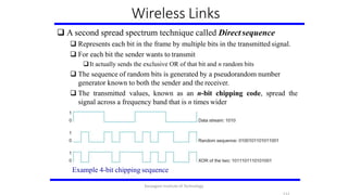
- 112. Wireless Links A second spread spectrum technique called Direct sequence Represents each bit in the frame by multiple bits in the transmitted signal. For each bit the sender wants to transmit It actually sends the exclusive OR of that bit and n random bits The sequence of random bits is generated by a pseudorandom number generator known to both the sender and the receiver. The transmitted values, known as an n-bit chipping code, spread the signal across a frequency band that is n times wider Example 4-bit chipping sequence Karpagam Institute of Technology
- 113. Wireless Links Wireless technologies differ in a variety of dimensions How much bandwidth they provide How far apart the communication nodes can be Four prominent wireless technologies: Bluetooth, Wi-Fi (more formally known as 802.11), WiMAX (802.16), 3G cellularwireless Overview of leading wireless technologies Karpagam Institute of Technology
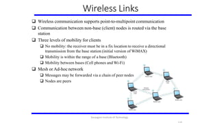
- 114. Wireless Links widely used links Mostly wireless are today usually asymmetric Two end-points are usually different kinds of nodes One end-point usually has no mobility, but has wired connection to the Internet base(known as station) The node at the other end of the link is often mobile A wireless network using a basestation Karpagam Institute of Technology
- 115. Wireless Links Wireless communication supports point-to-multipoint communication Communication between non-base (client) nodes is routed via the base station Three levels of mobility for clients No mobility: the receiver must be in a fix location to receive a directional transmission from the base station (initial version of WiMAX) Mobility is within the range of a base (Bluetooth) Mobility between bases (Cell phones and Wi-Fi) Mesh or Ad-hoc network Messages may be forwarded via a chain of peer nodes Nodes are peers Karpagam Institute of Technology
- 116. IEEE 802.11 Also known as Wi-Fi Like its Ethernet and token ring siblings, 802.11 is designed for use in a limited geographical area (homes, office buildings, campuses) Primary challenge is to mediate access to a shared communication medium – in this case, signals propagating throughspace 802.11 supports additional features power management and security mechanisms Original 802.11 standard defined two radio-based physical layerstandard One using the frequency hopping Over 79 1-MHz-wide frequency bandwidths Second using direct sequence Using 11-bit chipping sequence Both standards run in the 2.4-GHz and provide up to 2 Mbps Karpagam Institute of Technology
- 117. IEEE 802.11 Then physical layer standard 802.11b was added Using a variant of direct sequence 802.11b provides up to 11 Mbps Uses license-exempt 2.4-GHz band Then came 802.11a which delivers up to 54 Mbps using OFDM 802.11a runs on license-exempt 5-GHz band Most recent standard is 802.11g which is backward compatible with 802.11b Uses 2.4 GHz band, OFDM and delivers up to 54 Mbps Karpagam Institute of Technology
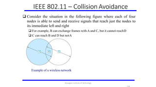
- 118. IEEE 802.11 – Collision Avoidance Consider the situation in the following figure where each of four nodes is able to send and receive signals that reach just the nodes to its immediate left and right For example, B can exchange frames with A and C, but it cannot reachD C can reach B and D but notA Example of a wireless network Karpagam Institute of Technology
- 119. IEEE 802.11 – Collision Avoidance Suppose both A and C want to communicate with B and so they each send it a frame. A and C are unaware of each other since their signals do not carry that far These two frames collide with each other at B But unlike an Ethernet, neither A nor C is aware of this collision A and C are said to hidden nodes with respect to each other The “Hidden Node” Problem.Although A and C are hidden from each other, their signals can collide at B. (B’s reach is not shown.) Karpagam Institute of Technology
- 120. IEEE 802.11 – Collision Avoidance Another problem called exposed node problem occurs Suppose B is sending to A. Node C is aware of this communication because it hears B’s transmission. It would be a mistake for C to conclude that it cannot transmit to anyone just because it can hear B’s transmission. Suppose C wants to transmit to node D. This is not a problem since C’s transmission to D will not interfere with A’sability to receive from B. Exposed Node Problem. Although B and C are exposed to each other’s signals, there is no interference if B transmits to A while C transmits to D. (A and D’s reaches are not shown.) Karpagam Institute of Technology
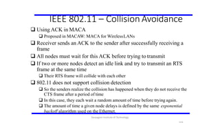
- 121. IEEE 802.11 – Collision Avoidance 802.11 addresses these two problems with an algorithm called Multiple Access with Collision Avoidance(MACA). Key Idea Sender and receiver exchange control frames with each other before the sender actually transmits any data. This exchange informs all nearby nodes that a transmission is about to begin Sender transmits a Request to Send (RTS) frame to the receiver. The RTS frame includes a field that indicates how long the sender wants to hold the medium - Length of the data frame to be transmitted Receiver replies with a Clear to Send (CTS) frame This frame echoes this length field back to the senderKarpagam Institute of Technology
- 122. IEEE 802.11 – Collision Avoidance Any node that sees the CTS frame knows that it is close to the receiver, therefore cannot transmit for the period of time it takes to send a fram the specified length Any node that sees the RTS frame but not the CTS frame is not close enough to the receiver to interfere with it, and so is free to transmit Karpagam Institute of Technology
- 123. IEEE 802.11 – Collision Avoidance Using ACK in MACA Proposed in MACAW: MACA for WirelessLANs Receiver sends an ACK to the sender after successfully receiving a frame All nodes must wait for this ACK before trying to transmit If two or more nodes detect an idle link and try to transmit an RTS frame at the same time Their RTS frame will collide with each other 802.11 does not support collision detection So the senders realize the collision has happened when they do not receive the CTS frame after a period of time In this case, they each wait a random amount of time before trying again. The amount of time a given node delays is defined by the same exponential backoff algorithm used on the Ethernet. Karpagam Institute of Technology
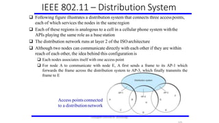
- 124. IEEE 802.11 – Distribution System 802.11 is suitable for an ad-hoc configuration of nodes that may or may not be able to communicate with all other nodes. Nodes are free to move around The set of directly reachable nodes may change over time To deal with this mobility and partial connectivity, 802.11 defines additional structures on a set of nodes Instead of all nodes being created equal, some nodes are allowed to roam some are connected to a wired network infrastructure they are called Access Points (AP) and they are connected to each other by a so-called distribution system Karpagam Institute of Technology
- 125. Following figure illustrates a distribution system that connects three accesspoints, each of which services the nodes in the same region Each of these regions is analogous to a cell in a cellular phone system withthe APIs playing the same role as a base station The distribution network runs at layer 2 of the ISO architecture Although two nodes can communicate directly with each other if they are within reach of each other, the idea behind this configuration is Each nodes associates itself with one access point For node A to communicate with node E, A first sends a frame to its AP-1 which forwards the frame across the distribution system to AP-3, which finally transmits the frame to E IEEE 802.11 – Distribution System Access points connected to a distribution network Karpagam Institute of Technology
- 126. IEEE 802.11 – Distribution System How do the nodes select their access points How does it work when nodes move from one cell to another The technique for selecting an AP is calledscanning The node sends a Probe frame All APs within reach reply with a Probe Responseframe The node selects one of the access points and sends that AP an Association Request frame The AP replies with an Association Responseframe A node engages this protocol whenever it joins the network, as well as when it becomes unhappy with its currentAP This might happen, for example, because the signal from its current AP has weakened due to the node moving away from it Whenever a node acquires a new AP, the new AP notifies the old AP of the change via the distribution system Karpagam Institute of Technology
- 127. Consider the situation shown in the following figure when node C moves fromthe cell serviced by AP-1 to the cell serviced byAP-2. As it moves, it sends Probe frames, which eventually result in ProbeResponses fromAP-2. At some point, C prefersAP-2 overAP-1 , and so it associates itself with that access point. This is called active scanning since the node is actively searching for an access point APs also periodically send a Beacon frame that advertises the capabilities of the access point; these include the transmission rate supported by the AP This is called passive scanning A node can change to this AP based on the Beacon frame simply by sending it an Association Request frame back to the access point. IEEE 802.11 – Distribution System Node Mobility Karpagam Institute of Technology
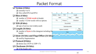
- 128. IEEE 802.11 – Frame Format Source and Destinations addresses: each 48 bits Data: up to 2312 bytes CRC: 32 bit Control field: 16 bits Contains three subfields (of interest) 6 bit Type field: indicates whether the frame is an RTS or CTS frame or being used by the scanning algorithm A pair of 1 bit fields : called ToDS and FromDS Frame Format Karpagam Institute of Technology
- 129. IEEE 802.11 – Frame Format Frame contains four addresses How these addresses are interpreted depends on the settings of the ToDS and FromDS bits in the frame’s Control field This is to account for the possibility that the frame had to be forwarded across the distribution system which would mean that, the original sender is not necessarily the same as the most recent transmitting node Same is true for the destination address Simplest case When one node is sending directly to another, both the DS bits are 0, Addr1 identifies the target node, andAddr2 identifies the source node Karpagam Institute of Technology
- 130. IEEE 802.11 – Frame Format Most complex case Both DS bits are set to 1 Indicates that the message went from a wireless node onto the distribution system, and then from the distribution system to another wireless node With both bits set, Addr1 identifies the ultimate destination, Addr2 identifies the immediate sender (the one that forwarded the frame from the distribution system to the ultimatedestination) Addr3 identifies the intermediate destination (the one that accepted the frame from a wireless node and forwarded across the distribution system) Addr4 identifies the original source Addr1: E,Addr2:AP-3,Addr3:AP-1,Addr4:A Karpagam Institute of Technology
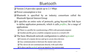
- 131. Bluetooth Used for very short range communication between mobile phones, PDAs, notebook computers and other personal or peripheral devices Operates in the license-exempt band at 2.45 GHz Has a range of only 10 m Communication typically belong to devices one individual or group Sometimes categorized as Personal Area Network (PAN) A BluetoothPiconet Karpagam Institute of Technology
- 132. Bluetooth Version 2.0 provides speeds up to 2.1 Mbps Power consumption is low Bluetooth is specified by an industry consortium called the Bluetooth Special Interest Group It specifies an entire suite of protocols, going beyond the link layer to define application protocols, which it calls profiles, for a range of applications There is a profile for synchronizing a PDA with personalcomputer Another profile gives a mobile computer access to a wired LAN The basic Bluetooth network configuration is called a piconet Consists of a master device and up to seven slave devices Any communication is between the master and a slave The slaves do not communicate directly with each other A slave can be parked: set to an inactive, low-powerstate Karpagam Institute of Technology
- 133. ZigBee ZigBee is a new technology that competes with Bluetooth Devised by the ZigBee alliance and standardized as IEEE 802.15.4 It is designed for situations where the bandwidth requirements are low and power consumption must be very low to give very long battery life It is also intended to be simpler and cheaper than Bluetooth, making it financially feasible to incorporate in cheaper devices such as a wall switch that wirelessly communicates with a ceiling-mounted fan Karpagam Institute of Technology
- 134. Switching and Forwarding Switch A mechanism that allows us to interconnect links to form a large network A multi-input, multi-output device which transfers packets from an input to one or more outputs A switch is connected to a set of links and for each of these links, runs the appropriate data link protocol to communicate with that node Adds the star topology to the links Karpagam Institute of Technology
- 135. Switching and Forwarding A switch’s primary job is to receive incoming packets on one of its links and to transmit them on some other link This function is referred as switching or forwarding According to OSI architecture this is the main function of the network layer How does the switch decide which output port to place each packet on? It looks at the header of the packet for an identifier that it uses to make the decision Two common approaches Datagram or Connectionless approach Virtual circuit or Connection-oriented approach A third approach source routing is less common Karpagam Institute of Technology
- 136. Switching and Forwarding packet contains Datagrams Key Idea Every enough information to enable any switch to decide how to get it to destination Every packet contains the complete destination address To decide how to forward a consults a forwarding packet, a switch table (sometimes called a routing table)An example network Dest Port ------------------- A 3 B 0 C 3 D 3 E 2 F 1 G 0 H 0 ForwardingTable for Switch2 Karpagam Institute of Technology
- 137. Switching and Forwarding Characteristics of Connectionless (Datagram) Network A host can send a packet anywhere at any time, since any packet that turns up at the switch can be immediately forwarded using the forwarding table When a host sends a packet, it does NOT know if the network is capable of delivering it or if the destination host is even up and running Each packet is forwarded independently of previous packets that might have been sent to the same destination. Thus two successive packets from host A to host B may follow completely different paths A switch or link failure might not have any serious effect on communication if it is possible to find an alternate route around the failure and update the forwarding table accordingly Virtual Circuit Switching (connection-oriented) Uses the concept of virtual circuit (VC) First set up a virtual connection from the source host to the destination host and then send the data Karpagam Institute of Technology
- 138. Switching and Forwarding Two-stage process Connection setup Data Transfer Host A wants tosend packets to host B Connection setup Establish “connection state” in each of the switches between the source and destination hosts The connection state for a single connection consists of an entry in the “VC table” in each switch through which the connection passes Karpagam Institute of Technology
- 139. Switching and Forwarding Characteristics of VC Since host A has to wait for the connection request to reach the far side of the network and return before it can send its first data packet, there is at least one RTT of delay before data is sent While the connection request contains the full address for host B (which might be quite large, being a global identifier on the network), each data packet contains only a small identifier, which is only unique on one link. Thus the per-packet overhead caused by the header is reduced relative to the datagram model If a switch or a link in a connection fails, the connection is broken and a new one will need to be established. Also the old one needs to be torn down to free up table storage space in the switches The issue of how a switch decides which link to forward the connection request on has similarities with the function of a routing algorithm Comparison with the Datagram Model Datagram network has no connection establishment phase and each switch processes each packet independently Each arriving packet competes with all other packets for buffer space If there are no buffers, the incoming packet must be dropped Karpagam Institute of Technology
- 140. Switching and Forwarding Good Properties of VC By the time the host gets the go-ahead to send data, it knows quite a lot about the network- For example, that there is really a route to the receiver and that the receiver is willing to receive data It is also possible to allocate resources to the virtual circuit at the time it is established X.25 network ( an early virtual-circuit-based networking technology but now largely obsolete) allocates buffers per VC In VC, we could imagine providing each circuit with a different quality of service (QoS) The network gives the user some kind of performance related guarantee Switches set aside the resources they need to meet this guarantee For example, a percentage of each outgoing link’s bandwidth Delay tolerance on each switch Most popular examples of VC technologies are X.25, Frame Relay andATM However, with the success of the Internet’s connection-less model, none of them enjoys great popularity today Karpagam Institute of Technology
- 141. Switching and Forwarding ATM (Asynchronous Transfer Mode) Most well-known VC-based networkingtechnology Somewhat pasts its peak in terms of deployment Was important in the 1980s and early 1990s High-speed switching technology Was thought of to take over the world Connection-oriented packet-switched network Packets are called cells 5 byte header + 48 byte payload Fixed length packets are easier to switch in hardware Simpler to design ATM VPI: Virtual Path Identifier CLP: Cell Loss Priority GFC: Generic Flow Control (not used) VCI: Virtual Circuit Identifier (VPI + VCI together makes the VC number we talked about) Type: management, congestion control HEC: Header Error Check (CRC-8) Karpagam Institute of Technology
- 142. Source Routing All the information about network topology that is required to switch a packet across the network is provided by the source host Notes on Source Routing Assumes that the source host knows enough about the topology of the network Analogous the problem of building the forwarding tables in datagram networks or figuring out where to send a setup packet in a virtual circuit network We can not predict how the header needs to be (# of switches in the path) Can be used in both datagram and virtual circuit networks For example, IP, which is a datagram protocol includes a source route option that allows selected packets to be source routed. Switching and Forwarding Karpagam Institute of Technology
- 143. Bridges and LAN Switches Bridges and LAN Switches Class of switches that is used to forward packets between shared-media LANs such as Ethernets Known as LAN switches Referred to as Bridges Suppose you have a pair of Ethernets that you want to interconnect One approach is put a repeater in between them It might exceed the physical limitation of theEthernet No more than four repeaters between any pair of hosts No more than a total of 2500 m in length isallowed An alternative would be to put a node between the two Ethernets and have the node forward frames from one Ethernet to the other This node is called a Bridge A collectionof LANs connected by one or more bridges is usually said to form an Extended LAN Simplest Strategy for Bridges Accept LAN frames on their inputs and forward them out to all other outputs Used by early bridges Learning Bridges Observe that there is no need to forward all the frames that a bridge receives Karpagam Institute of Technology
- 144. Consider the following figure When a frame from host A that is addressed to host B arrives on port 1, there is no need for the bridge to forward the frame out over port 2. How does a bridge come to learn on which port the various hosts reside? Solution Download a table into the bridge Who does the download? Human Too much work for maintenance Bridges and LAN Switches Host Port -------------------- A 1 B 1 C 1 X 2 Y 2 Z 2 Karpagam Institute of Technology
- 145. Bridges and LAN Switches Can the bridge learn this information by itself? Yes How Each bridge inspects the source address in all the frames it receives Record the information at the bridge and build the table When a bridge first boots, this table is empty Entries are added over time A timeout is associated with eachentry The bridge discards the entry after a specified period oftime To protect against the situation in which a host is moved from one network to another If the bridge receives a frame that is addressed to host not currently in the table Forward the frame out on all other ports Karpagam Institute of Technology
- 146. Bridges and LAN Switches Strategy works fine if the extended LAN does not have a loop in it Why? Frames potentially loop through the extended LAN forever Bridges B1, B4, and B6 form a loop Karpagam Institute of Technology
- 147. Bridges and LAN Switches How does an extended LAN come to have a loop in it? Network is managed by more than one administrator For example, it spans multiple departments in an organization It is possible that no single person knows the entire configuration of the network A bridge that closes a loop might be added without anyoneknowing to provideLoops are built into the network redundancy in case of failures Solution Distributed Spanning TreeAlgorithm 14 Karpagam Institute of Technology 147
- 148. Spanning TreeAlgorithm Think of the extended LAN as being represented by a graph that possibly has loops (cycles) A spanning tree is a sub-graph of this graph that covers all the vertices but contains no cycles Spanning tree keeps all the vertices of the original graph but throws out some of the edges Example of (a) a cyclic graph; (b) a corresponding spanning tree. 14 Karpagam Institute of Technology 148
- 149. Spanning TreeAlgorithm Developed by Radia Perlman at Digital A protocol used by a set of bridges to agree upon a spanning tree for a particular extended LAN IEEE 802.1 specification for LAN bridges is based on this algorithm Each bridge decides the ports over which it is and is not willing to forward frames In a sense the extended LAN is reduced to an acyclic tree Details are NOT required for the exam purposes Take point: Spanning Tree Algorithm removes the cycles/loops from the extended (bridged) LANs 14 Karpagam Institute of Technology 149
- 150. Limitation of Bridges Do not scale Spanning tree algorithm does not scale Broadcast does not scale Nodes get bothered with too many broadcasts that the bridges forward ALLnodes Do not accommodate heterogeneity Ethernet with Ethernet, Wi-Fi with Wi-Fi, etc. A solution Virtual LAN (VLAN) 15 Karpagam Institute of Technology 150
- 151. Virtual LANs (VLANs) Allow a single extended LAN to be partitioned into several logical LANs Each VLAN is assigned an ID (or color) Frames can only be travel between LANs segments within the same VLAN Partially solves the broadcast problem in the extended LAN One Attractive feature of VLANs is We can change the logical topology of the extended LAN without moving/changing any wire or addresses Just change the Bridge configuration 15 Karpagam Institute of Technology 151
- 152. Virtual LANs (VLANs) When a frame from X arrives at bridge B2, the bridge observes that it came in a port that was configured as being in VLAN 100, so it inserts a VLAN header (has the VLAN ID) between the Ethernet header and its payload When the frame arrives at B1, it will only forward it to the port of VLAN 100 and not to VLAN 200 The link between B1 and B2 is considered to be in both VLANs 15 Karpagam Institute of Technology 152
- 153. Internetworking What is internetwork An arbitrary collection of networks interconnected to provide some sortof host-to-host packet delivery service A simple internetwork where H represents hosts and R represents routers 15 Karpagam Institute of Technology 153
- 154. Internetworking What is IP IP stands for InternetProtocol Key tool used today to build scalable, heterogeneousinternetworks It runs on all the nodes in a collection of networks and defines the infrastructure that allows these nodes and networks to function as a single logical internetwork A simple internetwork showing the protocollayers 15 Karpagam Institute of Technology 154
- 155. IP Service Model Two parts Global Addressing Scheme Provides a way to identify all hosts in the network Datagram (Connectionless) model for data delivery Best-effort delivery (unreliable service) packets are lost packets are delivered out of order duplicate copies of a packet are delivered packets can be delayed for a long time 15 Karpagam Institute of Technology 155
- 156. Packet Format Version (4 bits): currently 4 or 6. Also called IPv4 and IPv6 Hlen (4 bits): number of 32-bit words in header usually 5 32-bit words with no options TOS (8 bits): type of service (not widely used) Length (16 bits): number of bytes in this datagram including the header Ident (16 bits) and Flags/Offset (16 bits): used by fragmentation Protocol (8 bits): demux key (TCP=6, UDP=17) Checksum (16 bits): of the header only 15 Karpagam Institute of Technology 156
- 157. Packet Format TTL (8 bits): number of hops/routers this packet can travel discard the looping packets Originally based on time, but changed to a hop-countbased Each router decrements it by 1 Discard the packet when it becomes 0 Default is 64 Problems Setting it too high the packet will loop a lot Setting it too low the packet will not reach the destination DestAddr & SrcAddr (32 bits) The key for datagram delivery Every packet contains a full destination address Forwarding/routing decisions are made at each router The source address is for the destination to know the sender and if it wants to reply to it 15 Karpagam Institute of Technology 157
- 158. IP Fragmentation and Reassembly Each network has some MTU (Maximum Transmission Unit) Ethernet (1500 bytes), FDDI (4500 bytes) IP packets need to fit in the payload of link-layerframe Solutions Make all packet size small enough to fit all Or fragment the large packets into smaller ones and reassembles them later Strategy Fragmentation occurs in a router when it receives a datagram that it wants to forward over a network which has (MTU < datagram) Reassembly is done at the receiving host All the fragments carry the same identifier in the Ident field Fragments are self-contained datagrams 15 Karpagam Institute of Technology 158
- 159. IP Fragmentation and Reassembly +Suppose PPP has MTU of 532-byte packet (20 header 512 payload) IP datagrams traversing the sequence of physicalnetworks Header fields used in IP fragmentation. (a) Unfragmented packet; (b) fragmented packets. MTU path discovery is a good strategy to avoid fragmentation Send some packets first just discover the MTUs on the path to D 15 Karpagam Institute of Technology 159
- 160. Global Addresses IP addresses Properties globally unique hierarchical: network + host Network part: identifies the network the host is attached to Host: identifies a unique host on that network Ethernet addresses, even globally unique, are flat (no structure and thus no meaning) and can not be use for routing Note that a router is attached to at least two networks, so it must have anIP address on each port/interface Thus it is more precise to think of IP addresses as belonging to interfaces rather than to hosts Approximately, 4 Billion IPaddress, half are A type, ¼ is B type, and 1/8 is Ctype (a) ClassA (b) Class B (c) Class C 16 Karpagam Institute of Technology 160
- 161. GlobalAddresses Class A was intended for Wide AreaNetworks Thus there should a very few of them Class B was intended for a modest size networks (like a campus) Class C is for the large number of LANs and today’s IP However, these classifications are not flexible addresses are normally “classless” as we will see Format 4 bytes, each byte is represented by a decimal number Dot notation 10.3.2.4 128.96.33.81 192.12.69.77 16 Karpagam Institute of Technology 161
- 162. IP Datagram Forwarding Strategy every datagram contains destination's address if directly connected to destination network, then forward tohost if not directly connected to destination network, then forward to somerouter forwarding table maps network number into next hop each host has a default router each router maintains a forwarding table Example (router R2) Algorithm if (NetworkNum of destination = NetworkNum of one of my interfaces)then deliver packet to destination over thatinterface else if (NetworkNum of destination is in my forwarding table)then deliver packet to NextHop router else deliver packet to default router For a host with only one interface and only a default router in its forwarding table, this simplifies to if (NetworkNum of destination = my NetworkNum)then deliver packet to destinationdirectly else deliver packet to default router 16 Karpagam Institute of Technology 162
- 163. Subnetting The network number part was designed to uniquely identify exactly one physical network However, this approach has some problems A network with only 2 hosts has to have at least a class C network!! A network with only 256 hosts has to have at least a class B network!! Thus, we will waste our valuable IP address space Solution: Subnetting Key Idea Allocate a single network number and use it for several physical networks - subnets Several things need to be done Subnets need to be physically close to each other From the Internet point of view, they all look ONE network A perfect situation to use subnetting is for large campus or corporation Configure all nodes on each subnet with a subnet mask It masks the network part Introduces the subnet number All nodes on the same subnet have the same subnet number and the same mask The IP address of a nodes ANDed with the subnet mask give the subnet number IP AND subnet mask subnet number 16 Karpagam Institute of Technology 163
- 164. Subnetting Increases the number of networks and reducesthe number of hosts When a host wants to send a packet to a certain IPaddress First, it does the bitwise AND between its own subnet mast and destination IP address If the result equals the subnet number of the sender, then the destination host is on the same subnet so the packet can be delivered directly (without a router) Else, the packet will be forwarded to another subnet (through a router) 16 Karpagam Institute of Technology 164
- 165. Subnetting Forwarding Table at Router R1 ForwardingAlgorithm D = destination IPaddress for each entry < SubnetNum, SubnetMask, NextHop> D1 = SubnetMask & D if D1 = SubnetNum if NextHop is an interface deliver datagram directly to destination else deliver datagram to NextHop (a router) 16Karpagam Institute of Technology 165
- 166. ClasslessAddressing Subnetting has a counterpart, sometimes called supernetting, but often called Classless Interdomain Routing, CIDR (pronounced cider) Address assignment efficiency A network with 256 hosts needs a class Baddress Address assignment efficiency = 256/65535 = 0.39 Solutions Use subnetting Only give class C networks Give class B only with a proof of that the network has more than 64K hosts Problem with this solution Excessive storage requirement at the routers. 16Karpagam Institute of Technology 166
- 167. ClasslessAddressing If a single site has, say 16 class C network numbers assigned to it, Every Internet backbone router needs 16 entries in its routing tables for that site (too much for one site) This is true, even if the path to every one of these networks is the same If we had assigned a class B address to theAS The same routing information can be stored in one entry Efficiency = number of hosts / number of available addresses =16 255 / 65, 536 = 6.2% (not efficient) CIDR tries to balance the desire to minimize the number of routes that a router needs to know against the need to hand out addresses efficiently. CIDR uses aggregate routes Uses a single entry in the forwarding table to tell the router how to reach a lot of different networks Breaks the rigid boundaries between address classes 16 Karpagam Institute of Technology 167
- 168. ClasslessAddressing Consider a site with 16 class C network numbers. Instead of handing out 16 addresses at random, hand out a block of contiguous class C addresses Suppose we assign the class C network numbers from 192.4.16 through 192.4.31 Observe that top 20 bits of all the addresses in this range are the same (11000000 00000100 0001) We have created a 20-bit network number (which is in between class B network number and class C number) Requires to hand out blocks of class C addresses that share a common prefix The convention is to place a /X after the prefix where X is the prefix length in bits 16 Karpagam Institute of Technology 168
- 169. ClasslessAddressing For example, the 20-bit prefix for all the networks 192.4.16 through 192.4.31 is represented as 192.4.16/20 By contrast, if we wanted to represent a single class C network number, which is 24 bits long, we would write it 192.4.16/24 Route aggregation with CIDR 16 Karpagam Institute of Technology 169
- 170. Different Protocols ARP (Address Resolution Protocol) DHCP (Dynamic Host Configuration Protocol) ICMP (Internet Control Message Protocol) 17 Karpagam Institute of Technology 170
- 171. Address Translation Protocol (ARP) Map IP addresses into physical addresses ARP (Address Resolution Protocol) table of IP to physical address bindings The router broadcasts a request (who-has / tell) if the required IP address not in the ARPtable Ex., who-has 192.168.0.29 tell 192.168.0.1 target machine (with IP 192.168.0.29 in the example) responds with its physical address (its MAC) 17 Karpagam Institute of Technology 171
- 172. Host IP Configurations Most host Operating Systems provide a way to manually configure the IP information for the host Drawbacks of manual configuration A lot of work to configure all the hosts in a large network Configuration process is error-prune Automated Configuration Process is required Using the DHCP protocol 17 Karpagam Institute of Technology 172
- 173. Dynamic Host Configuration Protocol DHCP server is responsible for providing configuration information to hosts There is at least one DHCP server for an administrative domain DHCP server maintains a pool/set of available addresses Newly booted or attached host sends DHCPDISCOVER message to a special IP address (255.255.255.255) DHCP relay agent unicasts the message to DHCP server and waits for the response 17 Karpagam Institute of Technology 173
- 174. Internet Control Message Protocol Defines a collection of error messages that are sent back to the source host whenever a router or host is unable to process an IP datagram successfully Destination host unreachable due to link /node failure Reassembly process failed TTL had reached 0 (so datagrams don't cycle forever) IP header checksum failed ICMP-Redirect From router to a source host With a better route information 17 Karpagam Institute of Technology 174
- 175. Routing Forwarding versus Routing Forwarding: to select an output port based on destination address and routing table Routing: routing table is built Network as a Graph The basic problem of routing is to find the lowest-cost path between anytwo nodes Where the cost of a path equals the sum of the costs of all the edgesthat make up the path 17 Karpagam Institute of Technology 175
- 176. Routing • For a simple network, we can calculate all shortest paths and load them into some nonvolatile storage on each node. • Such a static approach has several shortcomings • It does not deal with node or link failures • It does not consider the addition of new nodes or links • It implies that edge costs cannot change • What is the solution? • Need a distributed and dynamic protocol • Two main classes of protocols • Distance Vector • Link State Details are not required for the exam purposes 17 Karpagam Institute of Technology 176
- 177. SUMMARY • A media access control is a network data transfer policy that determines how data is transmitted between two computer terminals through a network cable. The media access control policy involves sub-layers of the data link layer 2 in the OSI reference model • An internetwork is a collection of individual networks, connected by intermediate networking devices, that functions as a single large network. Internetworking refers to the industry, products, and procedures that meet the challenge of creating and administering internetworks. Karpagam Institute of Technology 177
- 178. ASSIGNMENT QUESTIONS TOPIC LEVEL Compose controlled access methods with packet formats k2 Validate the network layer protocols and its types. k3 Compile IPv4 addresses with classful and classless addressing formats. k3 Karpagam Institute of Technology 178
- 179. VIDEO TUTORIAL Media Access Control https://www.coursera.org/lecture/peer-to-peer- protocols-local-area-networks/medium-access- control-nWWWd Karpagam Institute of Technology 179
- 180. QUIZ QUESTIONS 1. The Media access control layer frame has ------------------------------- a) 5 Fields b) 7 Fields c) 9 Fields d) 11 Fields 1. In Third generation of cellular telephony , the data rate for access in a moving vehicle is ------------------ a) 244 kbps b) 238 kbps c) 150 kbps d) 144 kbps 1. The field of the MAC frame that alter the receive and enables it to synchronize is known as ------------------------- a) SFD b) Preamble c) Source Address d) Designation Address 1. The value of the frame body field of Media Access Control frame is in between---------------------- a) 0 and 512 bytes b) 0 and 1214 bytes c) 0 to 2312 bytes d) 0 to 3450 bytes • 1. The duration field D of Media Access Control layer frame contains ----------------- a) 2 bytes b) 4 bytes c) 6 bytes d) 8 bytes. Karpagam Institute of Technology 180
- 181. 1. In ---------------------- methods, no station is superior to another station and none is assigned the control over another. a) Random access b) Controlled access c) Channelization d) None of the above 1. In----------------------- the chance, of collision can be reduced if a station sense the medium before trying to use it. a) MA b) CSMA c) FDMA d) CDMA. 1. ------------------------- requires that each station first listen to the medium before sending. a) MA b) CSMA c) CDMA d) FDMA 1. Media Access Control is the sub layer of -------------- a) LLC b) IEEE c) ANSI d) Both a and c. 1. -------------------------- augments the CSMA algorithm to detect collision a) CSMA/CD b) CSMA/CA c) Either (a) or(b) d) Both (a) and (b) Karpagam Institute of Technology 181
- 182. 1. Hardware address is known as----------------- a) MAC address b) IP Address c) Network Interface Card d) Address Resolution Protocol. 1. What translates IP address into MAC address? ------------------------ a) Organizationally Unique Identifier b) Address Resolution Protocol c) Network Interface Card d) Burned In Address 1. Networking Hardware Address is referred with---------------------- a) IP address b) MAC address c) NIC d) Organizationally Unique Identifier 1. Does MAC address contain characters.-------------------- a) True b) False. 1. On wireless networks--------------------- filtering is the security measure. a) OUI b) IP c) NIC d) MAC. Karpagam Institute of Technology 182
- 183. 1. MAC addresses are used as---------------------------- a) Network addresses b) IP address c) Hardware address d) Burned in address. 1. IEEE standards for Institute of Electrical and Electronics Engineers---------------- a) False b) True 1. The original IEEE 802 MAC address comes from-------------------- a) MAC address b) IP address c) Ethernet address d) Http. 1. MAC addresses are very useful in diagnosing network issues-------------- a) True b) False. 1. What is the size of MAC address? ------------- a) 16-bits b) 32-bits c) 48-bits d) 64-bits. Karpagam Institute of Technology 183
- 184. 1. 802.11 wireless networking uses what method as the media access method? --------------- a) CSMA/CD b) CTS/RTS c) CSMA/CA d) CSCD/CA 1. In ---------------------- each station sends a frame whenever it has a frame to send. a) Pure ALOHA b) Slotted ALOHA c) Both (a) and (b) d) Neither (a) nor (b). 1. In pure ALOHA, the vulnerable time is ----------------------- the frame transmission time. a) The same as b) Two times c) Three times. d) None of the above. 1. The maximum throughput for pure ALOHA is ------------------ percent a) 12.2 b) 18.4 c) 36.8 d) None of the above. 1. In -----------------------method a station cannot send unless it has been authorized by other stations. a) Random access b) Controlled access c) Channelization d) None of the above. Karpagam Institute of Technology 184
- 185. 1. The vulnerable time for CSMA is the --------------------------- propagation time. a) The same as b) Two times c) Three times d) None of the above. 1. In the ------------------------ method a station needs to make a reservation before sending data. Time is divided into intervals. a) Reservation b) Polling c) Token passing d) None of the above. 1. The channelization protocols---------------------- method. a) Two b) Three c) Four d) None of the above. 1. The popular controlled access -------------------- methods a) Two b) Three c) Four d) None of the above. 1. In--------------------- the available bandwidth is divided into frequency bands a) FDMA b) CDMA c) TDMA d) None of the above. Karpagam Institute of Technology 185
- 186. Unit - III ROUTING Karpagam Institute of Technology 186
- 187. Intra-AS Routing also known as interior gateway protocols (IGP) most common intra-AS routing protocols: RIP: Routing Information Protocol OSPF: Open Shortest Path First IGRP: Interior Gateway Routing Protocol (Cisco proprietary) 1 Karpagam Institute of Technology
- 188. RIP ( Routing Information Protocol) included in BSD-UNIX distribution in 1982 distance vector algorithm distance metric: # hops (max = 15 hops), each link has cost1 DVs exchanged with neighbors every 30 sec in response message(aka advertisement) each advertisement: list of up to 25 destination subnets (in IP addressing sense) DC u v A B w x y z subnet hops u 1 v 2 w 2 x 3 y 3 z 2 from router A to destinationsubnets: 1 Karpagam Institute of Technology
- 189. RIP: example w x z y A C routing table in router D D B destination subnet w y next router A B # hops to dest 2 2 z B 7 x -- 1 …. …. .... 1 Karpagam Institute of Technology
- 190. w x z y A D B C routing table in router D destination subnet w next router # A hops to dest 2 y B A 2 5 z B 7 x -- 1 …. …. .... dest next hops w x z …. - 1 - 1 C 4 … ... A-to-D advertisement RIP: example 1 Karpagam Institute of Technology 190
- 191. RIP: link failure, recovery if no advertisement heard after 180 sec --> neighbor/link declared dead routes via neighbor invalidated new advertisements sent to neighbors neighbors in turn send out new advertisements (if tables changed) link failure info quickly (?) propagates to entire net poison reverse used to prevent ping-pong loops (infinite distance = 16 hops) 1 Karpagam Institute of Technology 191
- 192. RIP table processing RIP routing tables managed by application- level process called route-d (daemon) physical link network (IP) forwarding table transport (UDP) advertisements sent periodically repeated routed physical link network (IP) transprt (UDP) in UDP packets, routed forwarding table 192 Karpagam Institute of Technology
- 193. OSPF (Open Shortest Path First) “open”: publicly available uses link state algorithm LS packet dissemination topology map at each node route computation using Dijkstra’s algorithm OSPF advertisement carries one entry per neighbor advertisements flooded to entire AS carried in OSPF messages directly over IP (rather than TCP or UDP IS-IS routing protocol: nearly identical to OSPF 193 Karpagam Institute of Technology
- 194. OSPF “advanced” features (not in RIP) security: all OSPF messages authenticated (to prevent malicious intrusion) multiple same-cost paths allowed (only one path in RIP) for each link, multiple cost metrics for different TOS (e.g., satellite link cost set “low” for best effort ToS; high for real time ToS) integrated uni- and multicast support: Multicast OSPF (MOSPF) uses same topology data base as OSPF hierarchical OSPF in large domains. 194 Karpagam Institute of Technology
- 195. Hierarchical OSPF boundary router backbone router area 1 area 2 area 3 backbone area border routers internal routers 195 Karpagam Institute of Technology
- 196. two-level hierarchy: local area, backbone. link-state advertisements only in area each nodes has detailed area topology; only know direction (shortest path) to nets in other areas. area border routers: “summarize” distances to nets in own area, advertise to other Area Border routers. backbone routers: run OSPF routing limited to backbone. boundary routers: connect to otherAS’s. Hierarchical OSPF 196 Karpagam Institute of Technology
- 197. Internet inter-AS routing: BGP BGP (Border Gateway Protocol): the de facto inter-domain routing protocol “glue that holds the Internet together” BGP provides each AS a means to: eBGP: obtain subnet reachability information from neighboring ASs. iBGP: propagate reachability information to all AS-internal routers. determine “good” routes to other networks based on reachability information and policy. allows subnet to advertise its existence to rest of Internet: “I am here” 197 Karpagam Institute of Technology
- 198. BGP basics AS2 3b 3a AS3 1c 1a AS1 1d 1b 2a 2c 2b other networks other networks BGP session: two BGP routers (“peers”) exchange BGP messages: advertising paths to different destination network prefixes (“pathvector” protocol) exchanged over semi-permanent TCPconnections when AS3 advertises a prefix toAS1: AS3 promises it will forward datagrams towards that prefix AS3 can aggregate prefixes in its advertisement 3c BGP message 198 Karpagam Institute of Technology
- 199. BGP: distributing path information AS2 3b 3a AS3 1c 1a AS1 1d 1b 2a 2c 2b other networks other networks using eBGP session between 3a and 1c, AS3 sendsprefix reachability info toAS1. 1c can then use iBGP do distribute new prefix info to all routers inAS1 1b can then re-advertise new reachability info to AS2 over1b- to-2a eBGP session when router learns of new prefix, it creates entry for prefix in its forwarding table. eBGP session iBGP session 199 Karpagam Institute of Technology
- 200. Path attributes and BGP routes advertised prefix includes BGP attributes prefix + attributes = “route” two important attributes: AS-PATH: contains ASs through which prefix advertisement has passed: e.g., AS 67, AS 17 NEXT-HOP: indicates specific internal-AS router to next-hop AS. (may be multiple links from current AS to next-hop-AS) gateway router receiving route advertisement uses import policy to accept/decline e.g., never route through AS x policy-based routing 200 Karpagam Institute of Technology
- 201. BGP route selection router may learn about more than 1 route to destination AS, selects route based on: local preference value attribute: policy decision shortestAS-PATH closest NEXT-HOP router: hot potato routing additional criteria 201 Karpagam Institute of Technology
- 202. BGP messages BGP messages exchanged between peers over TCP connection BGP messages: OPEN: opens TCP connection to peer and authenticates sender UPDATE: advertises new path (or withdraws old) KEEPALIVE: keeps connection alive in absence of UPDATES; also ACKs OPEN request NOTIFICATION: reports errors in previous msg; also used to close connection 202 Karpagam Institute of Technology
- 203. BGP routing policy A,B,C are provider networks X,W,Y are customer (of provider networks) X is dual-homed: attached to two networks X does not want to route from B via X to C .. so X will not advertise to B a route to C A B C W X Y legend: customer network: provider network 203 Karpagam Institute of Technology
- 204. BGP routing policy (2) A B C W X Y A advertises pathAW to B B advertises path BAW to X Should B advertise path BAW to C? No way! B gets no “revenue” for routing CBAW since neither W norC are B’s customers B wants to force C to route to w viaA B wants to route only to/from its customers! legend: customer network: provider network 204 Karpagam Institute of Technology
- 205. Why different Intra-, Inter-AS routing ? policy: inter-AS: admin wants control over how its traffic routed, who routes through its net. intra-AS: single admin, so no policy decisions needed scale: hierarchical routing saves table size, reduced update traffic performance: intra-AS: can focus on performance inter-AS: policy may dominate over performance 205 Karpagam Institute of Technology
- 206. The Global Internet The tree structure of the Internet in 1990 206 Karpagam Institute of Technology
- 207. The Global Internet A simple multi-providerInternet 207 Karpagam Institute of Technology
- 208. Interdomain Routing (BGP) Internet is organized as autonomous systems (AS) each of which is under the control of a single administrative entity Autonomous System (AS) corresponds to an administrative domain examples: University, company, backbone network A corporation’s internal network might be a single AS, as may the network of a single Internet service provider 208 Karpagam Institute of Technology
- 209. Interdomain Routing A network withtwo autonomous system 209 Karpagam Institute of Technology
- 210. Route Propagation Idea: Provide an additional way to hierarchically aggregate routing information is a large internet. Improves scalability Divide the routing problem in two parts: Routing within a single autonomous system Routing between autonomous systems in the Another name for autonomous systems Internet is routing domains Two-level route propagation hierarchy Inter-domain routing protocol (Internet-widestandard) Intra-domain routing protocol (each AS selects itsown) 210 Karpagam Institute of Technology
- 211. EGP and BGP Inter-domain Routing Protocols Exterior Gateway Protocol (EGP) Forced a tree-like topology onto the Internet Did not allow for the topology to become general Tree like structure: there is a single backbone and autonomous systems are connected only as parents and children and not aspeers Border Gateway Protocol (BGP) Assumes that the Internet is an arbitrarily interconnected set of ASs. Today’s Internet consists of an interconnection of multiple backbone networks (they are usually called service provider networks, and they are operated by private companies rather than the government) Sites are connected to each other in arbitrary ways 211 Karpagam Institute of Technology
- 212. BGP Some large corporations connect directly to one or more of the backbone, while others connect to smaller, non-backbone service providers. Many service providers exist mainly to provide service to “consumers” (individuals with PCs in their homes), and these providers must connect to the backbone providers Often many providers arrange to interconnect with each other at a single “peering point” 212 Karpagam Institute of Technology
- 213. BGP-4: Border Gateway Protocol Assumes the Internet is an arbitrarily interconnected set ofAS's. Define local traffic as traffic that originates at or terminates on nodes within an AS, and transit traffic as traffic that passes through anAS. We can classify AS's into three types: Stub AS: an AS that has only a single connection to one other AS; such an AS will only carry local traffic (small corporation in the figure of the previous page). Multihomed AS: an AS that has connections to more than one other AS, but refuses to carry transit traffic (large corporation at the top in the figure of the previous page). Transit AS: an AS that has connections to more than one other AS, and is designed to carry both transit and local traffic (backbone providers in the figure of the previous page). 213 Karpagam Institute of Technology
- 214. The goal of Inter-domain routing is to find any path to the intended destination that is loop free We are concerned with reachability than optimality Finding path anywhere close to optimal is considered to be a great achievement Why? BGP 214 Karpagam Institute of Technology
- 215. Scalability: An Internet backbone router must be able to forward any packet destined anywhere in the Internet Having a routing table that will provide a match for any valid IP address Autonomous nature of the domains It is impossible to calculate meaningful path costs for a path that crosses multipleASs A cost of 1000 across one provider might imply a great path but it might mean an unacceptable bad one from another provid Issues of trust Provider A might be unwilling to believe certain advertisements from provider B BGP 215 Karpagam Institute of Technology
- 216. Each AS has: One BGP speaker that advertises: local networks other reachable networks (transit AS only) gives path information In addition to the BGP speakers, the AS has one or more border “gateways” which need not be the same as the speakers The border gateways are the routers through which packets enter and leave theAS BGP 216 Karpagam Institute of Technology
- 217. BGP does not belong to either of the two main classes of routing protocols (distance vectors and link-state protocols) BGP advertises complete paths as an enumerated lists of ASs to reach a particular network BGP Example 217 Karpagam Institute of Technology
- 218. BGP Example Speaker for AS 2 advertises reachability to Pand Q Network 128.96, 192.4.153, 192.4.32, and 192.4.3, can be reached directly from AS 2. Speaker for backbone network then advertises Networks 128.96, 192.4.153, 192.4.32, and 192.4.3 can be reached along the path <AS 1, AS 2>. Speaker can also cancel previously advertised paths 218 Karpagam Institute of Technology
- 219. BGP Issues It should be apparent that the AS benumbers carried in BGP need to unique For example, AS 2 can only recognize itself in the AS path in the example if no other AS identifies itself in the same way AS numbers are 16-bit numbers assigned by a central authority 219 Karpagam Institute of Technology
- 220. Integrating Interdomain & Intradomain Routing All routers run iBGP and an intradomain routing protocol. Border routers (A, D, E) also run eBGP to otherASs 220 Karpagam Institute of Technology
- 221. Integrating Interdomain & Intradomain Routing BGP routing table, IGP routing table, and combined table at routerB 221 Karpagam Institute of Technology
- 222. RoutingAreas A domain divided intoarea router Backbone area Area border (ABR) 222 Karpagam Institute of Technology
- 223. Next Generation IP (IPv6) 223 Karpagam Institute of Technology
- 224. Major Features 128-bit addresses Multicast Real-time service Authentication and security Auto-configuration End-to-end fragmentation Enhanced routing functionality, including support for mobile hosts 224 Karpagam Institute of Technology
- 225. IPv6 Addresses Classless addressing/routing (similar to CIDR) Notation: x:x:x:x:x:x:x:x(x= 16-bit hex number) contiguous 0s are compressed: 47CD::A456:0124 IPv6 compatible IPv4 address: ::128.42.1.87 Address assignment provider-based geographic 225 Karpagam Institute of Technology
- 226. IPv6 Header 40-byte “base” header Extension headers (fixed order, mostly fixed length) fragmentation source routing authentication and security other options 226 Karpagam Institute of Technology
- 227. Internet Multicast 227 Karpagam Institute of Technology
- 228. Overview IPv4 class D addresses demonstrated with MBone uses tunneling Integral part of IPv6 problem is making it scale One-to-many Radio station broadcast Transmitting news, stock-price Software updates to multiple hosts 228 Karpagam Institute of Technology
- 229. Overview Many-to-many Multimedia teleconferencing Online multi-player games Distributed simulations Without support for multicast A source needs to send a separate packet with the identical data to each member of the group This redundancy consumes more bandwidth Redundant traffic is not evenly distributed, concentrated near the sending host Source needs to keep track of the IP address of each member in the group Group may be dynamic 22Karpagam Institute of Technology 229
- 230. Overview To support many-to-many and one-to-many IP provides an IP-level multicast Basic IP multicast model is many-to-many based on multicast groups Each group has its own IP multicast address Hosts that are members of a group receive copies of any packets sent to that group’s multicast address A host can be in multiple groups A host can join and leave groups 23Karpagam Institute of Technology 230
- 231. Overview Using IP multicast to send the identical packet to each member of the group A host sends a single copy of the packet addressed to the group’s multicast address The sending host does not need to know the individual unicast IP address of each member Sending host does not send multiple copies of the packet IP’s original many-to-many multicast has been supplemented with support for a form of one-to- many multicast 23Karpagam Institute of Technology 231
- 232. Overview One-to-many multicast Source specific multicast (SSM) A receiving host specifies both a multicast group and aspecific sending host Many-to-many model Any source multicast (ASM) A host signals its desire to join or leave a multicast groupby communicating with its local router using a special protocol In IPv4, the protocol is Internet Group Management Protocol (IGMP) In IPv6, the protocol is Multicast Listener Discovery (MLD) The router has the responsibility for making multicast behave correctly with regard to the host 232 Karpagam Institute of Technology
- 233. Multicast Routing A router’s unicast forwarding tables indicate for any IP address, which link to use to forward the unicast packet To support multicast, a router must additionally have multicast forwarding tables that indicate, based on multicast address, which links to use to forward the multicast packet Unicast forwarding tables collectively specify a set of paths Multicast forwarding tables collectively specify a set of trees Multicast distribution trees 233 Karpagam Institute of Technology
- 234. Multicast Routing To support source multicast forwarding specific multicast, the tables must indicate • which links to use based on the combination of multicast address the unicast IP address of the source Multicast routing is the process by which multicast distribution t are determined 234 Karpagam Institute of Technology
- 235. Distance Vector Multicast Each router already knows that shortest path to source S goes through router N. When receive multicast packet from S, forward on all outgoing links (except the one on which the packet arrived), iff packet arrived from N. onlyEliminate duplicate broadcast packets by letting “parent” for LAN (relative to S) forward shortest path to S (learn via distance vector) smallest address to break ties 235 Karpagam Institute of Technology
- 236. Reverse Path Broadcast (RPB) Goal: Prune networks that have no hosts in group G Step 1: Determine of LAN is a leaf with no members in G leaf if parent is only router on the LAN determine if any hosts are members of G using IGMP Step 2: Propagate “no members of G here” information augment <Destination, Cost> update sent to neighbors with set of groups for which this network is interested in receiving multicast packets. only happens when multicast address becomes active. Distance Vector Multicast 236 Karpagam Institute of Technology
- 237. Protocol Independent Multicast (PIM) Shared Tree Source specific tree 237 Karpagam Institute of Technology
- 238. Protocol Independent Multicast (PIM) Delivery of a packet along a shared tree. R1 tunnels the packet to the RP, which forwards it along the shared tree to R4 and R5. 238 Karpagam Institute of Technology
- 239. Routing for Mobile Hosts Mobile IP home agent Router located on the home network of the mobile hosts home address The permanent IP address of the mobile host. Has a network number equal to that of the home network and thus of the home agent foreign agent Router located on a network to which the mobile node attaches itself when it is away from its home network 239 Karpagam Institute of Technology
- 240. Routing for Mobile Hosts Problem of delivering a packet to the mobile node How does the home agent intercept a packet that is destined for the mobile node? ProxyARP How does the home agent then deliver the packet to the foreign agent? IP tunnel Care-of-address How does the foreign agent deliver the packet to the mobile node? 240 Karpagam Institute of Technology
- 241. Routing for Mobile Hosts Route optimization in Mobile IP The route from the sending node to mobile node can be significantly sub-optimal One extreme example The mobile node and the sending node are on the same network, but the home network for the mobile node is on the far side of the Internet Triangle Routing Problem Solution Let the sending node know the care-of-address of the mobile node. The sending node can create its own tunnel to the foreignagent Home agent sends binding update message The sending node creates an entry in the bindingcache The binding cache may become out-of-date The mobile node moved to a different network Foreign agent sends a binding warning message 241 Karpagam Institute of Technology
- 242. SUMMARY • Routers are physical devices that join multiple wired or wireless networks together. Technically, a wired or wireless router is a Layer 3 gateway, meaning that the wired/wireless router connects networks (as gateways do), and that the router operates at the network layer of the OSI model. Karpagam Institute of Technology 242
- 243. ASSIGNMENT QUESTIONS TOPIC LEVEL Elaborate in detail about the Address Space and Address Space Allocation and IPv6 addressing. k3 Develop the transition from IPv4 to IPv6 with its strategies and uses. k2 (i) Evaluate the working of Protocol Independent Multicast (PIM) in detail. (ii) Outline the need of DVMRP k3 Karpagam Institute of Technology 243
- 244. VIDEO TUTORIAL Introduction to Routing https://www.youtube.com/watch?v=Am lOSGYkKXc Routing 1 https://www.youtube.com/watch?v=u0B TdiqhVRI Karpagam Institute of Technology 244
- 245. • QUIZ QUESTIONS: 1. When a router cannot route a datagram, the datagram is discarded and send a message to source----------------------- a) Destination Unreachable b) Destination Unverified c) Destination Unavailable d) Destination no-entry. 1. When a router needs to send a packet destined for another network ,it must know the ----------------- a) Datagram b) Medium c) Path flow d) IP address 1. An option which is used to record the time of datagram processing by a router is called---------------- a) Timestamp b) Time frame c) Time delay d) Time wrap 1. A host or router can join a group by sending a -------------------- a) Initiative report b) Joining report c) Membership report message d) Membership Leave report 1. In network addresses, each router has two--------------- a) Addresses b) Masks c) Blocks d) Segments. Karpagam Institute of Technology 245
- 246. 1. Which of the following is not the requirement of routing function?----------------------- a) Correctness b) Robustness c) Delaytime d) Stability 1. The-----------------protocol allows the administrator to assign a cost,called the metric, to eachroute. a) OSPF b) RIP c) BGP d) BBGP 1. If there is only one routing sequence for each source destination pair, the scheme is known as ------------------------- a) static routing b) fixed alternative routing c) standard routing d) dynamic routing 1. The OpenShortest Path First(OSPF) protocol is an intra domain routing protocol basedon ------------------routing. a) distance vector b) link state c) path vector d) non distance vector 1. A ---------------------routing scheme is designed to enable switches to react to changing traffic patterns on the network. a) static routing b) fixed alternative routing c) standard routing d) dynamic routing. Karpagam Institute of Technology 246
- 247. 1. The Routing Information Protocol(RIP) is an intra domain routing basedon ---------------routing. a) distance vector b) link state c) path vector d) distance code 1. The term ------------- refers to which node or nodes in the network are responsible for the routing decision. a) decision place b) routing place c) node place d) switching place 1. In ------------------ routing the least cost route betweenany two nodes is the minimum distance. a) path vector b) distance vector c) link state d) switching 1. For centralized routing the decision is made by some designated node called----------------- a) designated center b) control center c) network center d) network control center 1. For purposesof routing, the Internet is divided into ---------------- a) wide area networks b) autonomous networks c) local area networks d) autonomous system Karpagam Institute of Technology 247
- 248. 1. In -------------------- a route is selectedfor eachdestination pair of nodes in the network a) Flooding b) variable routing c) fixed routing d) random routing. 1. To createa neighborhood relationship, a router running BGP sendsan -----------------message. a) Open b) Update c) keep alive d) Close 1. The technique which requires no network information required is--------------------- a) Flooding b) variable routing c) fixed routing d) random routing 1. An area is------------------- a) partof an AS b) composed of at least two AS c) another term for an AS d) composed more than two AS 1. Which of the following produces high traffic network? ----------------- a) Variable routing b) Flooding c) Fixed routing d) Random routing Karpagam Institute of Technology 248
- 249. 1. In ------------------ routing, we assume that there is one node (or more) in each autonomous system that acts on behave of the entire autonomous system. a) distant vector b) path vector c) link state d) multipoint 1. When a direct delivery is made, both the deliverer and receiver have the same--------------- a) routing table b) host id c) IP address d) Netid 1. In OSPF, a ------------------ link is a network with several routers attached to it. a) point-to-point b) transient c) Stub d) Multipoint 1. In ---------------------- routing, the mask and the destination addressare both 0.0.0.0in routing table. a) next-hop b) host-specific c) network-specific d) default 1. In--------------------------- the router forwards the receive packet through only one of its interfaces. a) unicasting b) Multicasting c) Broadcasting d) point to point Karpagam Institute of Technology 249
- 250. Karpagam Institute of Technology 250 1. An example of the routing algorithm is-------------------- a) TELNET b) TNET c) ARPANET d) ARNET 1. ----------------------- protocol is a popular example of a link-state routing protocol. a) SPF b) BGP c) RIP d) OSPF 1. Alternate and adaptive routing algorithm belongs to --------------------- a) static routing b) permanent routing c) standard routing d) dynamic routing 1. The Enhanced Interior Gateway Routing Protocol(EIGRP) is categorized as a------------------ a) Distance vector routing protocols b) Link state routing protocols c) Hybrid routing protocols d) Automatic state routing protocols 1. In ----------------routing, the routing table hold the address of just the next hop instead of complete route information. a) next-hop b) host-specific c) network-specific default.
- 251. • TEXT BOOK: • T1: Behrouz A. Forouzan, ―“Data communication and Networking”, Fifth Edition, Tata McGraw – Hill, 2013 (UNIT I –V) • REFERENCES: • R1 James F. Kurose, Keith W. Ross, “Computer Networking - A Top-Down Approach Featuring the Internet”, • seventh Edition, Pearson Education, 2016. • R2 Nader. F. Mir, “Computer and Communication Networks”, Pearson Prentice Hall Publishers, 2nd Edition, 2014. • R3 Ying-Dar Lin, Ren-Hung Hwang, Fred Baker, “Computer Networks: An Open Source Approach”, Mc Graw Hill • Publisher, 2011. • R4 Larry L. Peterson, Bruce S. Davie, “Computer Networks: A Systems Approach”, Fifth Edition, Morgan Kaufmann • Publishers, 2011. Karpagam Institute of Technology 251
- 252. THANK YOU Karpagam Institute of Technology 252