SlideShare a Scribd company logo
Service Repair Manual
Models
938F Wheel Loader
Shutdown SIS
Previous Screen
Product: WHEEL LOADER
Model: 938F WHEEL LOADER 8SM
Configuration: 938F WHEEL LOADER 8SM00001-UP (MACHINE) POWERED BY 3116 ENGINE
Disassembly and Assembly
938F WHEEL LOADER POWER TRAIN
Media Number -SENR6706-04 Publication Date -01/08/2004 Date Updated -26/10/2004
SENR67060026
Torque Converter
SMCS - 3101-015; 3101-016; 3150-015; 3150-016
Disassemble Torque Converter
Start By:
a. remove transmission and torque converter
b. separation of transmission from torque converter
1. Install Tool (A) as shown.
2. Remove six bolts (1).
3. Lift transmission cover (2) straight up and off the torque converter. The weight of the
transmission cover is 150 kg (330 lb).
1/70
938F WHEEL LOADER 8SM00001-UP (MACHINE) POWERED BY 3116 ENGIN...
2020/4/9
https://127.0.0.1/sisweb/sisweb/techdoc/techdoc_print_page.jsp?returnurl=/sisw...
4. Install Tool (A) as shown.
5. Remove eighteen bolts (2) and washers.
6. Install two forcing screws as shown.
7. Separate driver gear (3) and stator carrier (4) from rotating housing (5).
8. Remove six socket head bolts (6).
9. Remove two clamp plates (7).
10. Use Tool (B) to remove retaining ring (8).
2/70
938F WHEEL LOADER 8SM00001-UP (MACHINE) POWERED BY 3116 ENGIN...
2020/4/9
https://127.0.0.1/sisweb/sisweb/techdoc/techdoc_print_page.jsp?returnurl=/sisw...
11. Carefully tap stator carrier (4) from converter impeller (9).
12. Check seal ring (11) for damage or wear and replace if necessary.
13. Remove twelve bolts (12).
14. Remove drive gear (3) from converter impeller (9).
15. Use a suitable press to remove ball bearing from the converter impeller (9).
16. Use Tool (B) to remove retaining ring (14).
3/70
938F WHEEL LOADER 8SM00001-UP (MACHINE) POWERED BY 3116 ENGIN...
2020/4/9
https://127.0.0.1/sisweb/sisweb/techdoc/techdoc_print_page.jsp?returnurl=/sisw...
17. Lift converter turbine (15) from rotating housing (5).
18. Remove rear bearing lock (16).
19. Remove end cover (17).
20. Turn the rotating housing over and use a soft hammer to tap splined hub and ball bearing (18)
out of the housing.
4/70
938F WHEEL LOADER 8SM00001-UP (MACHINE) POWERED BY 3116 ENGIN...
2020/4/9
https://127.0.0.1/sisweb/sisweb/techdoc/techdoc_print_page.jsp?returnurl=/sisw...
21. Use Tool (B) to remove snap ring (19) from splined hub (18).
22. If necessary, remove ball bearing from splined hub.
23. Check the condition of locating ring (21) on the outside diameter of ball bearing (20) and
replace if necessary.
24. Check oil dam or "D" ring (22) for damage or wear and replace if necessary.
Assemble Torque Converter
1. Check oil dam or "D" ring (22) for damage or wear and replace if necessary.
2. Use Tool (B) to install snap ring (19) to splined hub (18).
3. If removed, install bearing (20) to splined hub (18).
5/70
938F WHEEL LOADER 8SM00001-UP (MACHINE) POWERED BY 3116 ENGIN...
2020/4/9
https://127.0.0.1/sisweb/sisweb/techdoc/techdoc_print_page.jsp?returnurl=/sisw...
4. Check the condition of locating ring (21) on the outside diameter of ball bearing (20) and
replace if necessary.
5. Turn the rotating housing over and assemble splined hub and bearing (18) to the housing.
6. Install end cover (17).
7. Install rear bearing lock (16).
8. Assemble converter turbine (15) to rotating housing (5).
6/70
938F WHEEL LOADER 8SM00001-UP (MACHINE) POWERED BY 3116 ENGIN...
2020/4/9
https://127.0.0.1/sisweb/sisweb/techdoc/techdoc_print_page.jsp?returnurl=/sisw...
9. Use Tool (B) to install retaining ring (14).
10. Heat bearing (13) to 135°C (275°F) and assemble to impeller (9).
11. Install drive gear (3) to impeller (9).
12. Install twelve bolts (12) and tighten to the torque of 30 ± 5 N·m (22 ± 4 lb ft).
13. Check seal ring (11) for damage or wear and replace if necessary.
14. If removed, install six spring pins (10).
7/70
938F WHEEL LOADER 8SM00001-UP (MACHINE) POWERED BY 3116 ENGIN...
2020/4/9
https://127.0.0.1/sisweb/sisweb/techdoc/techdoc_print_page.jsp?returnurl=/sisw...
15. Carefully install stator carrier (4) to impeller (9).
16. Install two clamp plates (7).
17. Use Tool (B) to install retaining ring (8).
18. Install six socket head bolts (6) and tighten to the torque of 30 ± 5 N·m (22 ± 4 lb ft).
19. Assemble drive gear (3) and stator carrier (4) to rotating housing (5).
8/70
938F WHEEL LOADER 8SM00001-UP (MACHINE) POWERED BY 3116 ENGIN...
2020/4/9
https://127.0.0.1/sisweb/sisweb/techdoc/techdoc_print_page.jsp?returnurl=/sisw...
20. Install Tool (A) as shown.
21. Install eighteen bolts (2) and washers and tighten to the torque of 30 ± 5 N·m (22 ± 4 lb ft).
22. Install Tool (A) as shown.
23. Use M10 Guide Bolts when lowering the transmission cover (2) straight down on the torque
converter. The weight of the transmission cover is 150 kg (330 lb).
24. Install six bolts (1) tighten to the torque of 55 ± 10 N·m (40 ± 7 lb ft).
End By:
a. connection of transmission to torque converter
a. install transmission and torque converter
Disassemble Transmission
9/70
938F WHEEL LOADER 8SM00001-UP (MACHINE) POWERED BY 3116 ENGIN...
2020/4/9
https://127.0.0.1/sisweb/sisweb/techdoc/techdoc_print_page.jsp?returnurl=/sisw...
Start By:
a. remove transmission
b. disassemble and assemble torque converter
c. disassemble transmission pump
1. Thoroughly clean the outside of the transmission (1) prior to disassembly.
2. Drain the transmission fluid into a suitable container.
3. Mark all parts and components for assembly purposes.
4. Remove bolt (2), retainer (3) and yoke (4).
5. Remove bolts (5) and retainer (6) (not shown). Check the O-ring seal (7) (not shown) behind
retainer (6) for damage or wear and replace if necessary. Remove brake drum (8).
10/70
938F WHEEL LOADER 8SM00001-UP (MACHINE) POWERED BY 3116 ENGI...
2020/4/9
https://127.0.0.1/sisweb/sisweb/techdoc/techdoc_print_page.jsp?returnurl=/sisw...
6. Remove four bolts (9). Remove tube assembly (10).
7. Check O-ring seal (11) (not shown) on each end of tube assembly for damage or wear and
replace if necessary.
8. Install Tool (A), chain and a suitable lifting device to shaft assembly (13) (forward shaft).
NOTE: Hold shaft assembly (12) away from shaft assembly (13) for clearance.
9. Slowly and carefully lift shaft assembly (13) straight up and out of case assembly (14). The
weight of the shaft assembly (13) is 41 kg (90 lb).
10. Install Tool (A), chain and a suitable lifting device to shaft assembly (15) (reverse shaft).
NOTE: Hold shaft assembly (12) away from shaft assembly (15) for clearance.
11. Slowly and carefully lift shaft assembly (15) straight up and out of case assembly (14). The
weight of the shaft assembly (15) is 46 kg (101 lb).
12. Remove input shaft (12).
11/70
938F WHEEL LOADER 8SM00001-UP (MACHINE) POWERED BY 3116 ENGI...
2020/4/9
https://127.0.0.1/sisweb/sisweb/techdoc/techdoc_print_page.jsp?returnurl=/sisw...
13. Install Tool (A), chain and a suitable lifting device to shaft assembly (16) (speed shaft).
14. Slowly and carefully, lift shaft assembly (16) straight up and out of case assembly (14). The
weight of the shaft assembly (16) is 80 kg (176 lb).
NOTE: There is a thrust disc that can fall off the bottom of the speed shaft upon removal. Take
care not to lose the thrust disc.
15. Install Tooling (B) (suitable puller group) and remove bearing (17) from output shaft (18).
16. Position shaft assembly (16) (speed shaft) on Tool (C).
NOTE: Use two flat plates marked (X) for added stability.
17. Use Tool (D) to remove retaining ring (19) and remove thrust disc (20).
12/70
938F WHEEL LOADER 8SM00001-UP (MACHINE) POWERED BY 3116 ENGI...
2020/4/9
https://127.0.0.1/sisweb/sisweb/techdoc/techdoc_print_page.jsp?returnurl=/sisw...
18. Remove gear (21).
19. Remove retaining ring (22) with Tool (D).
20. Separate hub assembly (23) from gear (21). If necessary, remove sleeve bearing (24).
21. Remove thrust disc (25) and retainer (26).
22. Use Tool (D) to remove retaining ring (27).
13/70
938F WHEEL LOADER 8SM00001-UP (MACHINE) POWERED BY 3116 ENGI...
2020/4/9
https://127.0.0.1/sisweb/sisweb/techdoc/techdoc_print_page.jsp?returnurl=/sisw...
23. Use Tool (E) and a suitable air supply to determine wear on the clutch plates and friction discs.
24. Nozzle used in step above.
25. Use a screwdriver to remove retaining ring (28).
26. Remove one end plate (29), clutch plates (31) and disc assembly (30).
27. Components in exploded view upon removal.
14/70
938F WHEEL LOADER 8SM00001-UP (MACHINE) POWERED BY 3116 ENGI...
2020/4/9
https://127.0.0.1/sisweb/sisweb/techdoc/techdoc_print_page.jsp?returnurl=/sisw...
28. Position the shaft assembly with retaining ring (32) as shown.
29. Install Tool (F), (I) and (J) to compress the wave spring (not shown).
30. Use Tool (D) to remove retaining ring (32). Release the pressure on the wave spring and
remove Tool (F).
31. Remove balance seal assembly (33).
32. Remove wave spring (34).
15/70
938F WHEEL LOADER 8SM00001-UP (MACHINE) POWERED BY 3116 ENGI...
2020/4/9
https://127.0.0.1/sisweb/sisweb/techdoc/techdoc_print_page.jsp?returnurl=/sisw...
Typical Example
33. Remove piston (35).
34. Remove balance seal assembly (33), wave spring (34) and piston seal assembly (35).
35. Use an eyebolt and a suitable lifting device to reposition the shaft assembly 180°.
36. Remove four seal rings (36).
16/70
938F WHEEL LOADER 8SM00001-UP (MACHINE) POWERED BY 3116 ENGI...
2020/4/9
https://127.0.0.1/sisweb/sisweb/techdoc/techdoc_print_page.jsp?returnurl=/sisw...
37. Remove thrust disc (37).
NOTE: This thrust disc may fall off when the shaft is removed from the case.
38. Use Tool (D) to remove retaining ring (38)
39. Remove gear (39).
40. Remove thrust disc (40).
17/70
938F WHEEL LOADER 8SM00001-UP (MACHINE) POWERED BY 3116 ENGI...
2020/4/9
https://127.0.0.1/sisweb/sisweb/techdoc/techdoc_print_page.jsp?returnurl=/sisw...
41. Remove gear and hub assembly (41).
42. Use Tool (G) to remove retaining ring (42).
43. Separate hub assembly (43) from gear (41).
44. If necessary, remove sleeve bearing (44). When installing sleeve bearing (44), press to a depth
of 10 mm (.4 in) from hub face.
45. Remove thrust disc (45) and ring retainer (46).
18/70
938F WHEEL LOADER 8SM00001-UP (MACHINE) POWERED BY 3116 ENGI...
2020/4/9
https://127.0.0.1/sisweb/sisweb/techdoc/techdoc_print_page.jsp?returnurl=/sisw...
46. Use Tool (E) and a suitable air nozzle to measure the travel of the clutch pack.
47. Use a screw driver to remove retaining ring (47).
48. Remove one end plate (48), clutch plates (49) and friction discs (50).
49. End plate (48), clutch plates (49) and friction discs (50) upon removal.
50. Use Tool (G) to remove snap ring (51).
19/70
938F WHEEL LOADER 8SM00001-UP (MACHINE) POWERED BY 3116 ENGI...
2020/4/9
https://127.0.0.1/sisweb/sisweb/techdoc/techdoc_print_page.jsp?returnurl=/sisw...
51. Position the shaft assembly so snap ring (52) lines up with the opening on Tool (H).
52. Install Tool (H), (I) and (J) to compress the wave spring (not shown). Use Tool (D) to remove
snap ring (52) and remove Tool (H).
53. Remove balance piston (53).
54. Remove wave spring (54).
20/70
938F WHEEL LOADER 8SM00001-UP (MACHINE) POWERED BY 3116 ENGI...
2020/4/9
https://127.0.0.1/sisweb/sisweb/techdoc/techdoc_print_page.jsp?returnurl=/sisw...
55. Remove piston (55).
56. Exploded view of balance piston (53), wave spring (54) and piston (55) upon removal.
57. Check lip seals (56) on piston (55) for damage or wear and replace if necessary.
NOTE: Seal lip must face toward the top of piston (55) as shown.
58. Check lip seal (57) on balance piston (53) for damage or wear and replace if necessary.
NOTE: Seal lip must face toward the tip of balance piston (53) as shown.
59. Shaft assembly (16) completely disassembled.
NOTE: There are three plugs on the end of the shaft assembly.
21/70
938F WHEEL LOADER 8SM00001-UP (MACHINE) POWERED BY 3116 ENGI...
2020/4/9
https://127.0.0.1/sisweb/sisweb/techdoc/techdoc_print_page.jsp?returnurl=/sisw...
60. Position reverse and second shaft assembly (58) on Tool (C) as shown. Use flat plates marked
(X) for stability.
61. Use Tool (D) to remove retaining ring (59) and remove thrust disc (60).
62. Remove gear and hub assembly (61).
63. Use Tool (G) to remove retaining ring (62).
64. Separate hub (63) from gear (61). If necessary, remove sleeve bearing (64).
22/70
938F WHEEL LOADER 8SM00001-UP (MACHINE) POWERED BY 3116 ENGI...
2020/4/9
https://127.0.0.1/sisweb/sisweb/techdoc/techdoc_print_page.jsp?returnurl=/sisw...
Thank you very much for
your reading. Please Click
Here. Then Get COMPLETE
MANUAL. NO WAITING
NOTE:
If there is no response to
click on the link above,
please download the PDF
document first and then
click on it.
65. Remove thrust disc (65) and retainer (66).
66. Use Tool (D) to remove retaining ring (67).
67. Use Tool (E) and a suitable air nozzle to check travel of the clutch plates.
68. Use a screw driver to remove retaining ring (68).
23/70
938F WHEEL LOADER 8SM00001-UP (MACHINE) POWERED BY 3116 ENGI...
2020/4/9
https://127.0.0.1/sisweb/sisweb/techdoc/techdoc_print_page.jsp?returnurl=/sisw...
69. Remove one end plate (61), clutch plates (62) and friction discs (63).
70. End plate (61), clutch plates (62) and friction discs (63).
71. Position the shaft assembly with retaining ring (64) in line with the opening in Tool (F).
72. Install Tool (F), (I) and (J) to compress the wave spring (not shown) and use Tool (D) to
remove retaining ring (64). Remove Tool (F).
73. Remove balance seal assembly (65).
24/70
938F WHEEL LOADER 8SM00001-UP (MACHINE) POWERED BY 3116 ENGI...
2020/4/9
https://127.0.0.1/sisweb/sisweb/techdoc/techdoc_print_page.jsp?returnurl=/sisw...
74. Remove wave spring (66).
Typical Example
75. Remove piston seal assembly (67).
76. Balance seal (65), wave spring (66) and piston seal (67) upon removal. Check the lip seals on
the balance and piston seals for damage or wear and replace if necessary.
77. Reposition the shaft assembly with opposite end up, as shown. Remove three seal rings (68),
use Tool (D) to remove retaining ring (69).
25/70
938F WHEEL LOADER 8SM00001-UP (MACHINE) POWERED BY 3116 ENGI...
2020/4/9
https://127.0.0.1/sisweb/sisweb/techdoc/techdoc_print_page.jsp?returnurl=/sisw...

More Related Content

PDF
Caterpillar cat 938 f wheel loader (prefix 8sm) service repair manual (8sm000...
PDF
Caterpillar cat 938 f wheel loader (prefix 7sn) service repair manual (7sn000...
PDF
Caterpillar Cat 938F Wheel Loader (Prefix 7SN) Service Repair Manual (7SN0000...
PDF
Caterpillar Cat 938F Wheel Loader (Prefix 7SN) Service Repair Manual (7SN0000...
PDF
Caterpillar Cat 938F Wheel Loader (Prefix 7SN) Service Repair Manual (7SN0000...
PDF
Caterpillar Cat 938F Wheel Loader (Prefix 7SN) Service Repair Manual Instant ...
PDF
Caterpillar cat 938 f wheel loader (prefix 7sn) service repair manual (7sn000...
PDF
Caterpillar Cat 938F Wheel Loader (Prefix 7SN) Service Repair Manual (7SN0000...
Caterpillar cat 938 f wheel loader (prefix 8sm) service repair manual (8sm000...
Caterpillar cat 938 f wheel loader (prefix 7sn) service repair manual (7sn000...
Caterpillar Cat 938F Wheel Loader (Prefix 7SN) Service Repair Manual (7SN0000...
Caterpillar Cat 938F Wheel Loader (Prefix 7SN) Service Repair Manual Instant ...
Caterpillar cat 938 f wheel loader (prefix 7sn) service repair manual (7sn000...
Caterpillar Cat 938F Wheel Loader (Prefix 7SN) Service Repair Manual (7SN0000...

Similar to Caterpillar Cat 938F WHEEL LOADER (Prefix 8SM) Service Repair Manual (8SM00001 and up).pdf (18)

PDF
Caterpillar Cat 938F Wheel Loader (Prefix 7SN) Service Repair Manual (7SN0000...
PDF
Caterpillar Cat 938F Wheel Loader (Prefix 7SN) Service Repair Manual (7SN0000...
PDF
Caterpillar Cat 938F Wheel Loader (Prefix 7SN) Service Repair Manual (7SN0000...
PDF
Caterpillar Cat 938F Wheel Loader (Prefix 7SN) Service Repair Manual (7SN0000...
PDF
Caterpillar Cat 938F Wheel Loader (Prefix 7SN) Service Repair Manual Instant ...
PDF
Caterpillar Cat 938F Wheel Loader (Prefix 7SN) Service Repair Manual Instant ...
PDF
Caterpillar cat 938 f wheel loader (prefix 7sn) service repair manual (7sn000...
PDF
Caterpillar cat 938 f wheel loader (prefix 7sn) service repair manual (7sn000...
PDF
Caterpillar cat 962 h wheel loader (prefix j6j) service repair manual (j6j005...
PDF
Caterpillar cat 962 h wheel loader (prefix j6j) service repair manual (j6j005...
PDF
Caterpillar cat 962 h wheel loader (prefix j6j) service repair manual (j6j005...
PDF
Caterpillar cat 962 h wheel loader (prefix j6j) service repair manual (j6j005...
PDF
Caterpillar Cat 962H WHEEL LOADER (Prefix J6J) Service Repair Manual Instant ...
PDF
Caterpillar Cat 962H WHEEL LOADER (Prefix J6J) Service Repair Manual (J6J0050...
PDF
Caterpillar Cat 962H WHEEL LOADER (Prefix J6J) Service Repair Manual (J6J0050...
PDF
Caterpillar Cat 962H WHEEL LOADER (Prefix J6J) Service Repair Manual (J6J0050...
PDF
Caterpillar Cat 962H WHEEL LOADER (Prefix J6J) Service Repair Manual (J6J0050...
PDF
Caterpillar Cat 962H WHEEL LOADER (Prefix J6J) Service Repair Manual (J6J0050...
Caterpillar Cat 938F Wheel Loader (Prefix 7SN) Service Repair Manual (7SN0000...
Caterpillar Cat 938F Wheel Loader (Prefix 7SN) Service Repair Manual Instant ...
Caterpillar cat 938 f wheel loader (prefix 7sn) service repair manual (7sn000...
Caterpillar cat 962 h wheel loader (prefix j6j) service repair manual (j6j005...
Caterpillar Cat 962H WHEEL LOADER (Prefix J6J) Service Repair Manual Instant ...
Caterpillar Cat 962H WHEEL LOADER (Prefix J6J) Service Repair Manual (J6J0050...

More from jdkskmmdmd1 (20)

PDF
Caterpillar Cat C27 Industrial Engine (Prefix TWM) Service Repair Manual (TWM...
PDF
Caterpillar Cat 938F Wheel Loader (Prefix 2RM) Service Repair Manual (2RM0000...
PDF
Caterpillar Cat C27 Industrial Engine (Prefix RAM) Service Repair Manual (RAM...
PDF
Caterpillar Cat C9 Industrial Engine (Prefix C9N) Service Repair Manual (C9N0...
PDF
Caterpillar Cat C9 Industrial Engine (Prefix MBD) Service Repair Manual (MBD0...
PDF
Caterpillar Cat C9 Industrial Engine (Prefix JLW) Service Repair Manual (JLW0...
PDF
Caterpillar Cat C27 Industrial Engine (Prefix AT4) Service Repair Manual (AT4...
PDF
Caterpillar Cat 345D L Excavator (Prefix EEH) Service Repair Manual (EEH00001...
PDF
Caterpillar Cat C27 Industrial Engine (Prefix JFJ) Service Repair Manual (JFJ...
PDF
Caterpillar Cat 345C L Excavator (Prefix TBA) Service Repair Manual (TBA00001...
PDF
Caterpillar Cat 345D L Excavator (Prefix KFH) Service Repair Manual (KFH00001...
PDF
Caterpillar Cat C9 Industrial Engine (Prefix JSC) Service Repair Manual (JSC0...
PDF
Caterpillar Cat 345C Hydraulic Excavator (Prefix ESD) Service Repair Manual (...
PDF
Massey Ferguson 1652 COMPACT TRACTORS Parts Catalogue Manual.pdf
PDF
Caterpillar Cat 345C Excavator (Prefix TBA) Service Repair Manual (TBA00001 a...
PDF
Caterpillar Cat 345D L Excavator (Prefix BYC) Service Repair Manual (BYC00001...
PDF
Caterpillar Cat 345C L Hydraulic Excavator (Prefix ESD) Service Repair Manual...
PDF
Caterpillar Cat 345C L Excavator (Prefix BWY) Service Repair Manual (BWY00001...
PDF
Massey Ferguson MF 840 COMBINES Parts Catalogue Manual.pdf
PDF
Massey Ferguson MF 845 COMBINES Parts Catalogue Manual.pdf
Caterpillar Cat C27 Industrial Engine (Prefix TWM) Service Repair Manual (TWM...
Caterpillar Cat 938F Wheel Loader (Prefix 2RM) Service Repair Manual (2RM0000...
Caterpillar Cat C27 Industrial Engine (Prefix RAM) Service Repair Manual (RAM...
Caterpillar Cat C9 Industrial Engine (Prefix C9N) Service Repair Manual (C9N0...
Caterpillar Cat C9 Industrial Engine (Prefix MBD) Service Repair Manual (MBD0...
Caterpillar Cat C9 Industrial Engine (Prefix JLW) Service Repair Manual (JLW0...
Caterpillar Cat C27 Industrial Engine (Prefix AT4) Service Repair Manual (AT4...
Caterpillar Cat 345D L Excavator (Prefix EEH) Service Repair Manual (EEH00001...
Caterpillar Cat C27 Industrial Engine (Prefix JFJ) Service Repair Manual (JFJ...
Caterpillar Cat 345C L Excavator (Prefix TBA) Service Repair Manual (TBA00001...
Caterpillar Cat 345D L Excavator (Prefix KFH) Service Repair Manual (KFH00001...
Caterpillar Cat C9 Industrial Engine (Prefix JSC) Service Repair Manual (JSC0...
Caterpillar Cat 345C Hydraulic Excavator (Prefix ESD) Service Repair Manual (...
Massey Ferguson 1652 COMPACT TRACTORS Parts Catalogue Manual.pdf
Caterpillar Cat 345C Excavator (Prefix TBA) Service Repair Manual (TBA00001 a...
Caterpillar Cat 345D L Excavator (Prefix BYC) Service Repair Manual (BYC00001...
Caterpillar Cat 345C L Hydraulic Excavator (Prefix ESD) Service Repair Manual...
Caterpillar Cat 345C L Excavator (Prefix BWY) Service Repair Manual (BWY00001...
Massey Ferguson MF 840 COMBINES Parts Catalogue Manual.pdf
Massey Ferguson MF 845 COMBINES Parts Catalogue Manual.pdf

Recently uploaded (20)

PDF
Presentation.pdf ...............gjtn....tdubsr..........
PPTX
Intro to ISO 9001 2015.pptx for awareness
PPTX
Independence_Day_Patriotic theme (1).pptx
PPTX
laws of thermodynamics with diagrams details
PPTX
1. introduction-to-bvcjdhjdfffffffffffffffffffffffffffffffffffmicroprocessors...
PDF
intrusion control for clean steel 123.pdf
PDF
Volvo EC290C NL EC290CNL Hydraulic Excavator Specs Manual.pdf
PDF
Volvo EC20C Excavator Service maintenance schedules.pdf
PPTX
Lecture 3b C Library xnxjxjxjxkx_ ESP32.pptx
PDF
harrier-ev-brochure___________________.pdf
PDF
Journal Meraj.pdfuuuuuuuuuuuuuuuuuuuuuuuuuuuuuuu
PDF
Physics class 12thstep down transformer project.pdf
PDF
RPL-ASDC PPT PROGRAM NSDC GOVT SKILLS INDIA
PPTX
729193dbwbsve251-Calabarzon-Ppt-Copy.pptx
PPT
ACCOMPLISHMENT REPOERTS AND FILE OF GRADE 12 2021.ppt
PPTX
Cloud_Computing_ppt[1].pptx132EQ342RRRRR1
PDF
EC290C NL EC290CNL - Volvo Service Repair Manual.pdf
PPTX
Gayatri Cultural Educational Society.pptx
PPTX
UNIT-2(B) Organisavtional Appraisal.pptx
PDF
Volvo EC20C Excavator Step-by-step Maintenance Instructions pdf
Presentation.pdf ...............gjtn....tdubsr..........
Intro to ISO 9001 2015.pptx for awareness
Independence_Day_Patriotic theme (1).pptx
laws of thermodynamics with diagrams details
1. introduction-to-bvcjdhjdfffffffffffffffffffffffffffffffffffmicroprocessors...
intrusion control for clean steel 123.pdf
Volvo EC290C NL EC290CNL Hydraulic Excavator Specs Manual.pdf
Volvo EC20C Excavator Service maintenance schedules.pdf
Lecture 3b C Library xnxjxjxjxkx_ ESP32.pptx
harrier-ev-brochure___________________.pdf
Journal Meraj.pdfuuuuuuuuuuuuuuuuuuuuuuuuuuuuuuu
Physics class 12thstep down transformer project.pdf
RPL-ASDC PPT PROGRAM NSDC GOVT SKILLS INDIA
729193dbwbsve251-Calabarzon-Ppt-Copy.pptx
ACCOMPLISHMENT REPOERTS AND FILE OF GRADE 12 2021.ppt
Cloud_Computing_ppt[1].pptx132EQ342RRRRR1
EC290C NL EC290CNL - Volvo Service Repair Manual.pdf
Gayatri Cultural Educational Society.pptx
UNIT-2(B) Organisavtional Appraisal.pptx
Volvo EC20C Excavator Step-by-step Maintenance Instructions pdf

Caterpillar Cat 938F WHEEL LOADER (Prefix 8SM) Service Repair Manual (8SM00001 and up).pdf

  • 2. Shutdown SIS Previous Screen Product: WHEEL LOADER Model: 938F WHEEL LOADER 8SM Configuration: 938F WHEEL LOADER 8SM00001-UP (MACHINE) POWERED BY 3116 ENGINE Disassembly and Assembly 938F WHEEL LOADER POWER TRAIN Media Number -SENR6706-04 Publication Date -01/08/2004 Date Updated -26/10/2004 SENR67060026 Torque Converter SMCS - 3101-015; 3101-016; 3150-015; 3150-016 Disassemble Torque Converter Start By: a. remove transmission and torque converter b. separation of transmission from torque converter 1. Install Tool (A) as shown. 2. Remove six bolts (1). 3. Lift transmission cover (2) straight up and off the torque converter. The weight of the transmission cover is 150 kg (330 lb). 1/70 938F WHEEL LOADER 8SM00001-UP (MACHINE) POWERED BY 3116 ENGIN... 2020/4/9 https://127.0.0.1/sisweb/sisweb/techdoc/techdoc_print_page.jsp?returnurl=/sisw...
  • 3. 4. Install Tool (A) as shown. 5. Remove eighteen bolts (2) and washers. 6. Install two forcing screws as shown. 7. Separate driver gear (3) and stator carrier (4) from rotating housing (5). 8. Remove six socket head bolts (6). 9. Remove two clamp plates (7). 10. Use Tool (B) to remove retaining ring (8). 2/70 938F WHEEL LOADER 8SM00001-UP (MACHINE) POWERED BY 3116 ENGIN... 2020/4/9 https://127.0.0.1/sisweb/sisweb/techdoc/techdoc_print_page.jsp?returnurl=/sisw...
  • 4. 11. Carefully tap stator carrier (4) from converter impeller (9). 12. Check seal ring (11) for damage or wear and replace if necessary. 13. Remove twelve bolts (12). 14. Remove drive gear (3) from converter impeller (9). 15. Use a suitable press to remove ball bearing from the converter impeller (9). 16. Use Tool (B) to remove retaining ring (14). 3/70 938F WHEEL LOADER 8SM00001-UP (MACHINE) POWERED BY 3116 ENGIN... 2020/4/9 https://127.0.0.1/sisweb/sisweb/techdoc/techdoc_print_page.jsp?returnurl=/sisw...
  • 5. 17. Lift converter turbine (15) from rotating housing (5). 18. Remove rear bearing lock (16). 19. Remove end cover (17). 20. Turn the rotating housing over and use a soft hammer to tap splined hub and ball bearing (18) out of the housing. 4/70 938F WHEEL LOADER 8SM00001-UP (MACHINE) POWERED BY 3116 ENGIN... 2020/4/9 https://127.0.0.1/sisweb/sisweb/techdoc/techdoc_print_page.jsp?returnurl=/sisw...
  • 6. 21. Use Tool (B) to remove snap ring (19) from splined hub (18). 22. If necessary, remove ball bearing from splined hub. 23. Check the condition of locating ring (21) on the outside diameter of ball bearing (20) and replace if necessary. 24. Check oil dam or "D" ring (22) for damage or wear and replace if necessary. Assemble Torque Converter 1. Check oil dam or "D" ring (22) for damage or wear and replace if necessary. 2. Use Tool (B) to install snap ring (19) to splined hub (18). 3. If removed, install bearing (20) to splined hub (18). 5/70 938F WHEEL LOADER 8SM00001-UP (MACHINE) POWERED BY 3116 ENGIN... 2020/4/9 https://127.0.0.1/sisweb/sisweb/techdoc/techdoc_print_page.jsp?returnurl=/sisw...
  • 7. 4. Check the condition of locating ring (21) on the outside diameter of ball bearing (20) and replace if necessary. 5. Turn the rotating housing over and assemble splined hub and bearing (18) to the housing. 6. Install end cover (17). 7. Install rear bearing lock (16). 8. Assemble converter turbine (15) to rotating housing (5). 6/70 938F WHEEL LOADER 8SM00001-UP (MACHINE) POWERED BY 3116 ENGIN... 2020/4/9 https://127.0.0.1/sisweb/sisweb/techdoc/techdoc_print_page.jsp?returnurl=/sisw...
  • 8. 9. Use Tool (B) to install retaining ring (14). 10. Heat bearing (13) to 135°C (275°F) and assemble to impeller (9). 11. Install drive gear (3) to impeller (9). 12. Install twelve bolts (12) and tighten to the torque of 30 ± 5 N·m (22 ± 4 lb ft). 13. Check seal ring (11) for damage or wear and replace if necessary. 14. If removed, install six spring pins (10). 7/70 938F WHEEL LOADER 8SM00001-UP (MACHINE) POWERED BY 3116 ENGIN... 2020/4/9 https://127.0.0.1/sisweb/sisweb/techdoc/techdoc_print_page.jsp?returnurl=/sisw...
  • 9. 15. Carefully install stator carrier (4) to impeller (9). 16. Install two clamp plates (7). 17. Use Tool (B) to install retaining ring (8). 18. Install six socket head bolts (6) and tighten to the torque of 30 ± 5 N·m (22 ± 4 lb ft). 19. Assemble drive gear (3) and stator carrier (4) to rotating housing (5). 8/70 938F WHEEL LOADER 8SM00001-UP (MACHINE) POWERED BY 3116 ENGIN... 2020/4/9 https://127.0.0.1/sisweb/sisweb/techdoc/techdoc_print_page.jsp?returnurl=/sisw...
  • 10. 20. Install Tool (A) as shown. 21. Install eighteen bolts (2) and washers and tighten to the torque of 30 ± 5 N·m (22 ± 4 lb ft). 22. Install Tool (A) as shown. 23. Use M10 Guide Bolts when lowering the transmission cover (2) straight down on the torque converter. The weight of the transmission cover is 150 kg (330 lb). 24. Install six bolts (1) tighten to the torque of 55 ± 10 N·m (40 ± 7 lb ft). End By: a. connection of transmission to torque converter a. install transmission and torque converter Disassemble Transmission 9/70 938F WHEEL LOADER 8SM00001-UP (MACHINE) POWERED BY 3116 ENGIN... 2020/4/9 https://127.0.0.1/sisweb/sisweb/techdoc/techdoc_print_page.jsp?returnurl=/sisw...
  • 11. Start By: a. remove transmission b. disassemble and assemble torque converter c. disassemble transmission pump 1. Thoroughly clean the outside of the transmission (1) prior to disassembly. 2. Drain the transmission fluid into a suitable container. 3. Mark all parts and components for assembly purposes. 4. Remove bolt (2), retainer (3) and yoke (4). 5. Remove bolts (5) and retainer (6) (not shown). Check the O-ring seal (7) (not shown) behind retainer (6) for damage or wear and replace if necessary. Remove brake drum (8). 10/70 938F WHEEL LOADER 8SM00001-UP (MACHINE) POWERED BY 3116 ENGI... 2020/4/9 https://127.0.0.1/sisweb/sisweb/techdoc/techdoc_print_page.jsp?returnurl=/sisw...
  • 12. 6. Remove four bolts (9). Remove tube assembly (10). 7. Check O-ring seal (11) (not shown) on each end of tube assembly for damage or wear and replace if necessary. 8. Install Tool (A), chain and a suitable lifting device to shaft assembly (13) (forward shaft). NOTE: Hold shaft assembly (12) away from shaft assembly (13) for clearance. 9. Slowly and carefully lift shaft assembly (13) straight up and out of case assembly (14). The weight of the shaft assembly (13) is 41 kg (90 lb). 10. Install Tool (A), chain and a suitable lifting device to shaft assembly (15) (reverse shaft). NOTE: Hold shaft assembly (12) away from shaft assembly (15) for clearance. 11. Slowly and carefully lift shaft assembly (15) straight up and out of case assembly (14). The weight of the shaft assembly (15) is 46 kg (101 lb). 12. Remove input shaft (12). 11/70 938F WHEEL LOADER 8SM00001-UP (MACHINE) POWERED BY 3116 ENGI... 2020/4/9 https://127.0.0.1/sisweb/sisweb/techdoc/techdoc_print_page.jsp?returnurl=/sisw...
  • 13. 13. Install Tool (A), chain and a suitable lifting device to shaft assembly (16) (speed shaft). 14. Slowly and carefully, lift shaft assembly (16) straight up and out of case assembly (14). The weight of the shaft assembly (16) is 80 kg (176 lb). NOTE: There is a thrust disc that can fall off the bottom of the speed shaft upon removal. Take care not to lose the thrust disc. 15. Install Tooling (B) (suitable puller group) and remove bearing (17) from output shaft (18). 16. Position shaft assembly (16) (speed shaft) on Tool (C). NOTE: Use two flat plates marked (X) for added stability. 17. Use Tool (D) to remove retaining ring (19) and remove thrust disc (20). 12/70 938F WHEEL LOADER 8SM00001-UP (MACHINE) POWERED BY 3116 ENGI... 2020/4/9 https://127.0.0.1/sisweb/sisweb/techdoc/techdoc_print_page.jsp?returnurl=/sisw...
  • 14. 18. Remove gear (21). 19. Remove retaining ring (22) with Tool (D). 20. Separate hub assembly (23) from gear (21). If necessary, remove sleeve bearing (24). 21. Remove thrust disc (25) and retainer (26). 22. Use Tool (D) to remove retaining ring (27). 13/70 938F WHEEL LOADER 8SM00001-UP (MACHINE) POWERED BY 3116 ENGI... 2020/4/9 https://127.0.0.1/sisweb/sisweb/techdoc/techdoc_print_page.jsp?returnurl=/sisw...
  • 15. 23. Use Tool (E) and a suitable air supply to determine wear on the clutch plates and friction discs. 24. Nozzle used in step above. 25. Use a screwdriver to remove retaining ring (28). 26. Remove one end plate (29), clutch plates (31) and disc assembly (30). 27. Components in exploded view upon removal. 14/70 938F WHEEL LOADER 8SM00001-UP (MACHINE) POWERED BY 3116 ENGI... 2020/4/9 https://127.0.0.1/sisweb/sisweb/techdoc/techdoc_print_page.jsp?returnurl=/sisw...
  • 16. 28. Position the shaft assembly with retaining ring (32) as shown. 29. Install Tool (F), (I) and (J) to compress the wave spring (not shown). 30. Use Tool (D) to remove retaining ring (32). Release the pressure on the wave spring and remove Tool (F). 31. Remove balance seal assembly (33). 32. Remove wave spring (34). 15/70 938F WHEEL LOADER 8SM00001-UP (MACHINE) POWERED BY 3116 ENGI... 2020/4/9 https://127.0.0.1/sisweb/sisweb/techdoc/techdoc_print_page.jsp?returnurl=/sisw...
  • 17. Typical Example 33. Remove piston (35). 34. Remove balance seal assembly (33), wave spring (34) and piston seal assembly (35). 35. Use an eyebolt and a suitable lifting device to reposition the shaft assembly 180°. 36. Remove four seal rings (36). 16/70 938F WHEEL LOADER 8SM00001-UP (MACHINE) POWERED BY 3116 ENGI... 2020/4/9 https://127.0.0.1/sisweb/sisweb/techdoc/techdoc_print_page.jsp?returnurl=/sisw...
  • 18. 37. Remove thrust disc (37). NOTE: This thrust disc may fall off when the shaft is removed from the case. 38. Use Tool (D) to remove retaining ring (38) 39. Remove gear (39). 40. Remove thrust disc (40). 17/70 938F WHEEL LOADER 8SM00001-UP (MACHINE) POWERED BY 3116 ENGI... 2020/4/9 https://127.0.0.1/sisweb/sisweb/techdoc/techdoc_print_page.jsp?returnurl=/sisw...
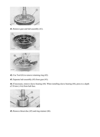
  • 19. 41. Remove gear and hub assembly (41). 42. Use Tool (G) to remove retaining ring (42). 43. Separate hub assembly (43) from gear (41). 44. If necessary, remove sleeve bearing (44). When installing sleeve bearing (44), press to a depth of 10 mm (.4 in) from hub face. 45. Remove thrust disc (45) and ring retainer (46). 18/70 938F WHEEL LOADER 8SM00001-UP (MACHINE) POWERED BY 3116 ENGI... 2020/4/9 https://127.0.0.1/sisweb/sisweb/techdoc/techdoc_print_page.jsp?returnurl=/sisw...
  • 20. 46. Use Tool (E) and a suitable air nozzle to measure the travel of the clutch pack. 47. Use a screw driver to remove retaining ring (47). 48. Remove one end plate (48), clutch plates (49) and friction discs (50). 49. End plate (48), clutch plates (49) and friction discs (50) upon removal. 50. Use Tool (G) to remove snap ring (51). 19/70 938F WHEEL LOADER 8SM00001-UP (MACHINE) POWERED BY 3116 ENGI... 2020/4/9 https://127.0.0.1/sisweb/sisweb/techdoc/techdoc_print_page.jsp?returnurl=/sisw...
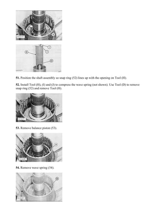
  • 21. 51. Position the shaft assembly so snap ring (52) lines up with the opening on Tool (H). 52. Install Tool (H), (I) and (J) to compress the wave spring (not shown). Use Tool (D) to remove snap ring (52) and remove Tool (H). 53. Remove balance piston (53). 54. Remove wave spring (54). 20/70 938F WHEEL LOADER 8SM00001-UP (MACHINE) POWERED BY 3116 ENGI... 2020/4/9 https://127.0.0.1/sisweb/sisweb/techdoc/techdoc_print_page.jsp?returnurl=/sisw...
  • 22. 55. Remove piston (55). 56. Exploded view of balance piston (53), wave spring (54) and piston (55) upon removal. 57. Check lip seals (56) on piston (55) for damage or wear and replace if necessary. NOTE: Seal lip must face toward the top of piston (55) as shown. 58. Check lip seal (57) on balance piston (53) for damage or wear and replace if necessary. NOTE: Seal lip must face toward the tip of balance piston (53) as shown. 59. Shaft assembly (16) completely disassembled. NOTE: There are three plugs on the end of the shaft assembly. 21/70 938F WHEEL LOADER 8SM00001-UP (MACHINE) POWERED BY 3116 ENGI... 2020/4/9 https://127.0.0.1/sisweb/sisweb/techdoc/techdoc_print_page.jsp?returnurl=/sisw...
  • 23. 60. Position reverse and second shaft assembly (58) on Tool (C) as shown. Use flat plates marked (X) for stability. 61. Use Tool (D) to remove retaining ring (59) and remove thrust disc (60). 62. Remove gear and hub assembly (61). 63. Use Tool (G) to remove retaining ring (62). 64. Separate hub (63) from gear (61). If necessary, remove sleeve bearing (64). 22/70 938F WHEEL LOADER 8SM00001-UP (MACHINE) POWERED BY 3116 ENGI... 2020/4/9 https://127.0.0.1/sisweb/sisweb/techdoc/techdoc_print_page.jsp?returnurl=/sisw...
  • 24. Thank you very much for your reading. Please Click Here. Then Get COMPLETE MANUAL. NO WAITING NOTE: If there is no response to click on the link above, please download the PDF document first and then click on it.
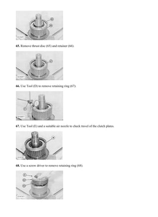
  • 25. 65. Remove thrust disc (65) and retainer (66). 66. Use Tool (D) to remove retaining ring (67). 67. Use Tool (E) and a suitable air nozzle to check travel of the clutch plates. 68. Use a screw driver to remove retaining ring (68). 23/70 938F WHEEL LOADER 8SM00001-UP (MACHINE) POWERED BY 3116 ENGI... 2020/4/9 https://127.0.0.1/sisweb/sisweb/techdoc/techdoc_print_page.jsp?returnurl=/sisw...
  • 26. 69. Remove one end plate (61), clutch plates (62) and friction discs (63). 70. End plate (61), clutch plates (62) and friction discs (63). 71. Position the shaft assembly with retaining ring (64) in line with the opening in Tool (F). 72. Install Tool (F), (I) and (J) to compress the wave spring (not shown) and use Tool (D) to remove retaining ring (64). Remove Tool (F). 73. Remove balance seal assembly (65). 24/70 938F WHEEL LOADER 8SM00001-UP (MACHINE) POWERED BY 3116 ENGI... 2020/4/9 https://127.0.0.1/sisweb/sisweb/techdoc/techdoc_print_page.jsp?returnurl=/sisw...
  • 27. 74. Remove wave spring (66). Typical Example 75. Remove piston seal assembly (67). 76. Balance seal (65), wave spring (66) and piston seal (67) upon removal. Check the lip seals on the balance and piston seals for damage or wear and replace if necessary. 77. Reposition the shaft assembly with opposite end up, as shown. Remove three seal rings (68), use Tool (D) to remove retaining ring (69). 25/70 938F WHEEL LOADER 8SM00001-UP (MACHINE) POWERED BY 3116 ENGI... 2020/4/9 https://127.0.0.1/sisweb/sisweb/techdoc/techdoc_print_page.jsp?returnurl=/sisw...