SlideShare a Scribd company logo
Detailed Presentation on UML
Akul Nigam(9911103424)
Devesh Vashishtha(9911103451)
Kartik Chaudhary(9911103477)
Ritvik Bhardwaj(9911103529)
Overview
• What is UML?
• Understanding the basics of UML
• Why UML?
• UML diagrams
• UML Modeling tools
What is UML?
• UML stands for “Unified Modeling Language”
• Modeling is describing system at a high level of
abstraction
• It is a industry-standard graphical language for
specifying, visualizing, constructing, and
documenting the artifacts of software systems
• The UML uses mostly graphical notations to express
the OO analysis and design of software projects.
• Simplifies the complex process of software design
Why UML for Modeling/Benefits of UML
• Use graphical notation to communicate more
clearly than natural language (imprecise) and
code(too detailed).
• Quick understanding
• Help acquire an overall view of a system.
• Lessens chances of conflicts.
• UML is not dependent on any one language or
technology.
• Necessary to manage complexity.
• UML moves us from fragmentation to
standardization.
Types of UML Diagrams
• Use Case Diagram
• Class Diagram
• Activity Diagram
• Sequence Diagram
• Collaboration Diagram
• State Diagram
• Deployment Diagram
Use Case Diagram
• Used for describing a set of user scenarios
• Illustrates functionality provided by the
system
• Mainly used for capturing user requirements
• Work like a contract between end user and
software developers
Use Case Diagram (core components)
Actors: A role that a user plays with respect to the system,including
human users and other systems. e.g.,inanimate physical objects (e.g. robot);
an external system that needs some information from the current system.
Use case: A set of scenarios that describing an interaction between a user
and a system, including alternatives.
System boundary: rectangle diagram representing the boundary
between the actors and the system.
Use Case Diagram(core relationship)
Association: communication between an actor and
a use case; Represented by a solid line.
Generalization: relationship between one general
use case and a special use case (used for defining
special alternatives)
Represented by a line with a triangular arrow head
toward the parent use case.
Use Case Diagram(core relationship)
Extend: a dotted line labeled <<extend>> with an arrow
toward the base case. The extending use case may add behavior to
the base use case. The base class declares “extension points”.
<<extend>>
Include: a dotted line labeled <<include>> beginning at base
use case and ending with an arrows pointing to the include
use case. The include relationship occurs when a chunk of
behavior is similar across more than one use case. Use
“include” in stead of copying the description of that behavior.
<<include>>
Use Case Diagrams
Library System
Borrow
Order Title
Fine Remittance
Client
Employee
Supervisor
• A generalized description of how a system will be used.
• Provides an overview of the intended functionality of the system
Boundary
Actor
Use Case
Use Case Diagrams(cont.)
•Pay Bill is a parent use case and Bill Insurance is the
child use case. (generalization)
•Both Make Appointment and Request Medication
include Check Patient Record as a subtask.(include)
•The extension point is written inside the base case
Pay bill; the extending class Defer payment adds the
behavior of this extension point. (extend)
Class diagram
• Used for describing structure and behavior in
the use cases
• Provide a conceptual model of the system in
terms of entities and their relationships
• Used for requirement capture, end-user
interaction
• Detailed class diagrams are used for
developers
Class representation
• Each class is represented by a rectangle subdivided into three
compartments
– Name
– Attributes
– Operations
• Modifiers are used to indicate visibility of attributes and operations.
– ‘+’ is used to denote Public visibility (everyone)
– ‘#’ is used to denote Protected visibility (friends and derived)
– ‘-’ is used to denote Private visibility (no one)
• By default, attributes are hidden and operations are visible.
An example of Class
Account_Name
- Customer_Name
- Balance
+addFunds( )
+withDraw( )
+transfer( )
Name
Attributes
Operations
OO Relationships
• There are two kinds of Relationships
– Generalization (parent-child relationship)
– Association (student enrolls in course)
• Associations can be further classified as
– Aggregation
– Composition
Subtype2
Supertype
Subtype1
OO Relationships: Generalization
- Generalization expresses a
parent/child relationship among related
classes.
- Used for abstracting details in several
layers
Regular
Customer
Loyalty
Customer
CustomerExample:
Regular
Customer
Loyalty
Customer
Customeror:
OO Relationships: Association
• Represent relationship between instances of
classes
– Student enrolls in a course
– Courses have students
– Courses have exams
– Etc.
• Association has two ends
– Role names (e.g. enrolls)
– Multiplicity (e.g. One course can have many students)
– Navigability (unidirectional, bidirectional)
Association: Multiplicity and Roles
University Person
1
0..1
*
*
Multiplicity
Symbol Meaning
1 One and only one
0..1 Zero or one
M..N From M to N (natural language)
* From zero to any positive integer
0..* From zero to any positive integer
1..* From one to any positive integer
teacheremployer
Role
Role
“A given university groups many people;
some act as students, others as teachers.
A given student belongs to a single
university; a given teacher may or may not
be working for the university at a particular
time.”
student
Association: Model to Implementation
Class Student {
Course enrolls[4];
}
Class Course {
Student have[];
}
Student Course
enrollshas
* 4
OO Relationships: Composition
Class W
Class P1 Class P2
Composition: expresses a relationship among instances
of related classes. It is a specific kind of Whole-Part
relationship.
It expresses a relationship where an instance of the
Whole-class has the responsibility to create and initialize
instances of each Part-class.
It may also be used to express a relationship where instances
of the Part-classes have privileged access or visibility to
certain attributes and/or behaviors defined by the
Whole-class.
Composition should also be used to express relationship where
instances of the Whole-class have exclusive access to and
control of instances of the Part-classes.
Composition should be used to express a relationship where
the behavior of Part instances is undefined without being
related to an instance of the Whole. And, conversely, the
behavior of the Whole is ill-defined or incomplete if one or
more of the Part instances are undefined.
Whole Class
Part Classes
Automobile
Engine Transmission
Example
OO Relationships: Aggregation
Class C
Class E1 Class E2
AGGREGATION
Aggregation: expresses a relationship among instances
of related classes. It is a specific kind of Container-
Containee
relationship.
It expresses a relationship where an instance of the
Container-class has the responsibility to hold and
maintain
instances of each Containee-class that have been created
outside the auspices of the Container-class.
Aggregation should be used to express a more informal
relationship than composition expresses. That is, it is an
appropriate relationship where the Container and its
Containees can be manipulated independently.
Aggregation is appropriate when Container and
Containees have no special access privileges to each other.
Container Class
Containee Classes
Bag
Apples Milk
Example
Aggregation vs. Composition
•CompositionComposition is really a strong form of aggregation
•components have only one owner
•components cannot exist independent of their owner
•components live or die with their owner
e.g. Each car has an engine that can not be shared with
other cars.
•Aggregations may form "part of" the aggregate, but may not
be essential to it. They may also exist independent of the
aggregate.
e.g. Apples may exist independent of the bag.
Class Diagram Example
Hotel Management System
Activity Diagram
• Procedural flow of control between two or more
class objects
• Activities are grouped into swim lanes.
• Activity is modeled by drawing a rectangle with
rounded edges, enclosing the activity's name.
• Connected to other activities through transition
lines
• Activities that terminate the modeled process are
connected to a termination point
Activity diagram, with
two swim lanes to
indicate control
of activity by two
objects: the band
manager, and the
reporting tool
Sequence Diagram
• Two dimensional
• Vertical dimension shows sequence of
messages in the time order that they occur.
• Horizontal dimension shows the object
instances to which the messages are sent.
• Self-Call can also be there in which a message
that an object sends to itself.
Sequence Diagram(make a phone call)
Caller Phone Recipient
Picks up
Dial tone
Dial
Ring notification Ring
Picks up
Hello
Sequence Diagrams – Object Life Spans
• Creation
– Create message
– Object life starts at that point
• Activation
– Symbolized by rectangular stripes
– Place on the lifeline where object is
activated.
– Rectangle also denotes when object
is deactivated.
• Deletion
– Placing an ‘X’ on lifeline
– Object’s life ends at that point
Activation bar
A
B
Create
X
Deletion
Return
Lifeline
Sequence Diagram
User Catalog Reservations
1: look up ()
2: title data ()
3: [not available] reserve title ()
4 : title returned ()
5: hold title ()
5 : title available ()
6 : borrow title ()
6 : remove reservation ()
Issuing a book from library
Collaboration Diagram
• Shows the relationship between objects
and the order of messages passed
between them.
• The objects are listed as rectangles and
arrows indicate the messages being
passed
• Convey the same information as
sequence diagrams, but focus on object
roles instead of the time sequence.
Collaboration diagrams of earlier made sequence diagram of issuing of book
from library
User
Catalog
Reservations
start
1: look up
2: title data
3 : [not available] reserve title
4 : title returned
5 : hold title
6 : borrow title
6: remove reservation
5: title available
State Diagrams
State Diagrams show the sequences of states an object goes through during
its life cycle in response to stimuli, together with its responses and actions;
an abstraction of all possible behaviors.
Unpaid
Start End
Paid
Invoice created paying Invoice destroying
(Billing Example)
Deployment Diagram
• System will be physically deployed in the
hardware environment
• System's production staff makes its
considerable use
• Purpose is to show where the different
components of the system will physically run
and how they will communicate with each
other
Deployment for ATM Machine
UML Modeling Tools
• Rational Rose (www.rational.com) by IBM
• TogetherSoft Control Center, Borland (
http://www.borland.com/together/index.html)
• ArgoUML (free software) (http://argouml.tigris.org/ )
OpenSource; written in javawritten in java
• Others (http://www.objectsbydesign.com/tools/umltools_byCompany.html )
Thank You!

More Related Content

PPTX
Overview of UML Diagrams
Manish Kumar
 
PPTX
Uml Presentation
mewaseem
 
PPT
Uml class Diagram
Satyamevjayte Haxor
 
PPTX
Use case diagram
City University
 
PDF
Sequence diagram- UML diagram
Ramakant Soni
 
PPT
UML
iQra Rafaqat
 
PPT
Uml class-diagram
ASHOK KUMAR PALAKI
 
Overview of UML Diagrams
Manish Kumar
 
Uml Presentation
mewaseem
 
Uml class Diagram
Satyamevjayte Haxor
 
Use case diagram
City University
 
Sequence diagram- UML diagram
Ramakant Soni
 
Uml class-diagram
ASHOK KUMAR PALAKI
 

What's hot (20)

PPTX
object oriented methodologies
Amith Tiwari
 
DOCX
Behavioural modelling
Benazir Fathima
 
PPT
Uml diagrams
barney92
 
PPTX
Ooad unit – 1 introduction
Babeetha Muruganantham
 
PPT
Uml
Sulman Ahmed
 
PPTX
Unified process model
RyndaMaala
 
PPTX
Object Oriented Analysis (Coad-Yourdon)
Subash Khatiwada
 
PDF
INTRODUCTION TO UML DIAGRAMS
Ashita Agrawal
 
PPT
11 deployment diagrams
Baskarkncet
 
PDF
Object Oriented Analysis Design using UML
Ajit Nayak
 
PPT
Use Case Diagram
Kumar
 
PDF
Object oriented-systems-development-life-cycle ppt
Kunal Kishor Nirala
 
PPT
Object Oriented Design
Sudarsun Santhiappan
 
PPTX
Software process
Jennifer Polack
 
PPTX
Relational Database Design
Archit Saxena
 
PPTX
Query processing and optimization (updated)
Ravinder Kamboj
 
PPTX
Importance & Principles of Modeling from UML Designing
ABHISHEK KUMAR
 
PPT
UML diagrams and symbols
Kumar
 
PPTX
Activity diagram
LOKENDRA PRAJAPATI
 
PPTX
PROTOTYPE MODEL
shenagarg44
 
object oriented methodologies
Amith Tiwari
 
Behavioural modelling
Benazir Fathima
 
Uml diagrams
barney92
 
Ooad unit – 1 introduction
Babeetha Muruganantham
 
Unified process model
RyndaMaala
 
Object Oriented Analysis (Coad-Yourdon)
Subash Khatiwada
 
INTRODUCTION TO UML DIAGRAMS
Ashita Agrawal
 
11 deployment diagrams
Baskarkncet
 
Object Oriented Analysis Design using UML
Ajit Nayak
 
Use Case Diagram
Kumar
 
Object oriented-systems-development-life-cycle ppt
Kunal Kishor Nirala
 
Object Oriented Design
Sudarsun Santhiappan
 
Software process
Jennifer Polack
 
Relational Database Design
Archit Saxena
 
Query processing and optimization (updated)
Ravinder Kamboj
 
Importance & Principles of Modeling from UML Designing
ABHISHEK KUMAR
 
UML diagrams and symbols
Kumar
 
Activity diagram
LOKENDRA PRAJAPATI
 
PROTOTYPE MODEL
shenagarg44
 
Ad

Similar to UML Diagrams (20)

PPT
UML Introduction The system development life cycle (SDLC) is a complex projec...
ssuserdb9909
 
PPT
umlpresentation-140519151641-phpapp02.ppt
FootballToday3
 
PPT
Uml report
Franco Valdez
 
PPT
Fundamentals of Software Engineering
Madhar Khan Pathan
 
PPT
Uml lecture
Inocentshuja Ahmad
 
PPTX
UML Chart Designing Methods - Lecture.pptx
lankanking4
 
PDF
UML Overview and Introduction functions.pdf
prathipaceec
 
PPT
Uml - An Overview
Raj Thilak S
 
PPT
Unified Modeling Language
Debajyoti Biswas
 
PPT
uml2-1214558329929112-8.ppt
AleksandarUrdarevski
 
PDF
UML, ER and Dimensional Modelling
Stefano Dalla Palma
 
PPT
CASE Tools lab.ppt
RAJESH S
 
PPTX
UML_Lecture.pptxnd bfdjjrnekdddkeeeenekejneje
ssusera6a60c1
 
PPTX
UML
Jazib Amjad
 
PPT
ASP.NET System design 2
Sisir Ghosh
 
PPTX
Unified Modeling Language and Examples .pptx
abinaya707644
 
PPTX
UML Diagram @ Software engineering discussion
CherryBerry2
 
PDF
2 class use case
Minal Maniar
 
PPT
08 class and sequence diagrams
kebsterz
 
PPTX
UML Design Document Training Learn UML .pptx
raghavanp4
 
UML Introduction The system development life cycle (SDLC) is a complex projec...
ssuserdb9909
 
umlpresentation-140519151641-phpapp02.ppt
FootballToday3
 
Uml report
Franco Valdez
 
Fundamentals of Software Engineering
Madhar Khan Pathan
 
Uml lecture
Inocentshuja Ahmad
 
UML Chart Designing Methods - Lecture.pptx
lankanking4
 
UML Overview and Introduction functions.pdf
prathipaceec
 
Uml - An Overview
Raj Thilak S
 
Unified Modeling Language
Debajyoti Biswas
 
uml2-1214558329929112-8.ppt
AleksandarUrdarevski
 
UML, ER and Dimensional Modelling
Stefano Dalla Palma
 
CASE Tools lab.ppt
RAJESH S
 
UML_Lecture.pptxnd bfdjjrnekdddkeeeenekejneje
ssusera6a60c1
 
ASP.NET System design 2
Sisir Ghosh
 
Unified Modeling Language and Examples .pptx
abinaya707644
 
UML Diagram @ Software engineering discussion
CherryBerry2
 
2 class use case
Minal Maniar
 
08 class and sequence diagrams
kebsterz
 
UML Design Document Training Learn UML .pptx
raghavanp4
 
Ad

Recently uploaded (20)

PDF
Virat Kohli- the Pride of Indian cricket
kushpar147
 
PDF
BÀI TẬP TEST BỔ TRỢ THEO TỪNG CHỦ ĐỀ CỦA TỪNG UNIT KÈM BÀI TẬP NGHE - TIẾNG A...
Nguyen Thanh Tu Collection
 
PPTX
Artificial Intelligence in Gastroentrology: Advancements and Future Presprec...
AyanHossain
 
PDF
Antianginal agents, Definition, Classification, MOA.pdf
Prerana Jadhav
 
PPTX
Basics and rules of probability with real-life uses
ravatkaran694
 
PPTX
An introduction to Dialogue writing.pptx
drsiddhantnagine
 
DOCX
Modul Ajar Deep Learning Bahasa Inggris Kelas 11 Terbaru 2025
wahyurestu63
 
PPTX
How to Close Subscription in Odoo 18 - Odoo Slides
Celine George
 
PPTX
HISTORY COLLECTION FOR PSYCHIATRIC PATIENTS.pptx
PoojaSen20
 
PPTX
How to Track Skills & Contracts Using Odoo 18 Employee
Celine George
 
PPTX
Sonnet 130_ My Mistress’ Eyes Are Nothing Like the Sun By William Shakespear...
DhatriParmar
 
PPTX
A Smarter Way to Think About Choosing a College
Cyndy McDonald
 
PPTX
Tips Management in Odoo 18 POS - Odoo Slides
Celine George
 
PDF
The Minister of Tourism, Culture and Creative Arts, Abla Dzifa Gomashie has e...
nservice241
 
PPTX
How to Manage Leads in Odoo 18 CRM - Odoo Slides
Celine George
 
PDF
What is CFA?? Complete Guide to the Chartered Financial Analyst Program
sp4989653
 
PPTX
HEALTH CARE DELIVERY SYSTEM - UNIT 2 - GNM 3RD YEAR.pptx
Priyanshu Anand
 
PPTX
CONCEPT OF CHILD CARE. pptx
AneetaSharma15
 
DOCX
Unit 5: Speech-language and swallowing disorders
JELLA VISHNU DURGA PRASAD
 
PPTX
Introduction to pediatric nursing in 5th Sem..pptx
AneetaSharma15
 
Virat Kohli- the Pride of Indian cricket
kushpar147
 
BÀI TẬP TEST BỔ TRỢ THEO TỪNG CHỦ ĐỀ CỦA TỪNG UNIT KÈM BÀI TẬP NGHE - TIẾNG A...
Nguyen Thanh Tu Collection
 
Artificial Intelligence in Gastroentrology: Advancements and Future Presprec...
AyanHossain
 
Antianginal agents, Definition, Classification, MOA.pdf
Prerana Jadhav
 
Basics and rules of probability with real-life uses
ravatkaran694
 
An introduction to Dialogue writing.pptx
drsiddhantnagine
 
Modul Ajar Deep Learning Bahasa Inggris Kelas 11 Terbaru 2025
wahyurestu63
 
How to Close Subscription in Odoo 18 - Odoo Slides
Celine George
 
HISTORY COLLECTION FOR PSYCHIATRIC PATIENTS.pptx
PoojaSen20
 
How to Track Skills & Contracts Using Odoo 18 Employee
Celine George
 
Sonnet 130_ My Mistress’ Eyes Are Nothing Like the Sun By William Shakespear...
DhatriParmar
 
A Smarter Way to Think About Choosing a College
Cyndy McDonald
 
Tips Management in Odoo 18 POS - Odoo Slides
Celine George
 
The Minister of Tourism, Culture and Creative Arts, Abla Dzifa Gomashie has e...
nservice241
 
How to Manage Leads in Odoo 18 CRM - Odoo Slides
Celine George
 
What is CFA?? Complete Guide to the Chartered Financial Analyst Program
sp4989653
 
HEALTH CARE DELIVERY SYSTEM - UNIT 2 - GNM 3RD YEAR.pptx
Priyanshu Anand
 
CONCEPT OF CHILD CARE. pptx
AneetaSharma15
 
Unit 5: Speech-language and swallowing disorders
JELLA VISHNU DURGA PRASAD
 
Introduction to pediatric nursing in 5th Sem..pptx
AneetaSharma15
 

UML Diagrams

  • 1. Detailed Presentation on UML Akul Nigam(9911103424) Devesh Vashishtha(9911103451) Kartik Chaudhary(9911103477) Ritvik Bhardwaj(9911103529)
  • 2. Overview • What is UML? • Understanding the basics of UML • Why UML? • UML diagrams • UML Modeling tools
  • 3. What is UML? • UML stands for “Unified Modeling Language” • Modeling is describing system at a high level of abstraction • It is a industry-standard graphical language for specifying, visualizing, constructing, and documenting the artifacts of software systems • The UML uses mostly graphical notations to express the OO analysis and design of software projects. • Simplifies the complex process of software design
  • 4. Why UML for Modeling/Benefits of UML • Use graphical notation to communicate more clearly than natural language (imprecise) and code(too detailed). • Quick understanding • Help acquire an overall view of a system. • Lessens chances of conflicts. • UML is not dependent on any one language or technology. • Necessary to manage complexity. • UML moves us from fragmentation to standardization.
  • 5. Types of UML Diagrams • Use Case Diagram • Class Diagram • Activity Diagram • Sequence Diagram • Collaboration Diagram • State Diagram • Deployment Diagram
  • 6. Use Case Diagram • Used for describing a set of user scenarios • Illustrates functionality provided by the system • Mainly used for capturing user requirements • Work like a contract between end user and software developers
  • 7. Use Case Diagram (core components) Actors: A role that a user plays with respect to the system,including human users and other systems. e.g.,inanimate physical objects (e.g. robot); an external system that needs some information from the current system. Use case: A set of scenarios that describing an interaction between a user and a system, including alternatives. System boundary: rectangle diagram representing the boundary between the actors and the system.
  • 8. Use Case Diagram(core relationship) Association: communication between an actor and a use case; Represented by a solid line. Generalization: relationship between one general use case and a special use case (used for defining special alternatives) Represented by a line with a triangular arrow head toward the parent use case.
  • 9. Use Case Diagram(core relationship) Extend: a dotted line labeled <<extend>> with an arrow toward the base case. The extending use case may add behavior to the base use case. The base class declares “extension points”. <<extend>> Include: a dotted line labeled <<include>> beginning at base use case and ending with an arrows pointing to the include use case. The include relationship occurs when a chunk of behavior is similar across more than one use case. Use “include” in stead of copying the description of that behavior. <<include>>
  • 10. Use Case Diagrams Library System Borrow Order Title Fine Remittance Client Employee Supervisor • A generalized description of how a system will be used. • Provides an overview of the intended functionality of the system Boundary Actor Use Case
  • 12. Use Case Diagrams(cont.) •Pay Bill is a parent use case and Bill Insurance is the child use case. (generalization) •Both Make Appointment and Request Medication include Check Patient Record as a subtask.(include) •The extension point is written inside the base case Pay bill; the extending class Defer payment adds the behavior of this extension point. (extend)
  • 13. Class diagram • Used for describing structure and behavior in the use cases • Provide a conceptual model of the system in terms of entities and their relationships • Used for requirement capture, end-user interaction • Detailed class diagrams are used for developers
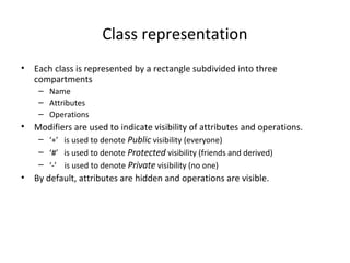
  • 14. Class representation • Each class is represented by a rectangle subdivided into three compartments – Name – Attributes – Operations • Modifiers are used to indicate visibility of attributes and operations. – ‘+’ is used to denote Public visibility (everyone) – ‘#’ is used to denote Protected visibility (friends and derived) – ‘-’ is used to denote Private visibility (no one) • By default, attributes are hidden and operations are visible.
  • 15. An example of Class Account_Name - Customer_Name - Balance +addFunds( ) +withDraw( ) +transfer( ) Name Attributes Operations
  • 16. OO Relationships • There are two kinds of Relationships – Generalization (parent-child relationship) – Association (student enrolls in course) • Associations can be further classified as – Aggregation – Composition
  • 17. Subtype2 Supertype Subtype1 OO Relationships: Generalization - Generalization expresses a parent/child relationship among related classes. - Used for abstracting details in several layers Regular Customer Loyalty Customer CustomerExample: Regular Customer Loyalty Customer Customeror:
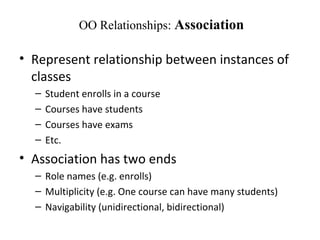
  • 18. OO Relationships: Association • Represent relationship between instances of classes – Student enrolls in a course – Courses have students – Courses have exams – Etc. • Association has two ends – Role names (e.g. enrolls) – Multiplicity (e.g. One course can have many students) – Navigability (unidirectional, bidirectional)
  • 19. Association: Multiplicity and Roles University Person 1 0..1 * * Multiplicity Symbol Meaning 1 One and only one 0..1 Zero or one M..N From M to N (natural language) * From zero to any positive integer 0..* From zero to any positive integer 1..* From one to any positive integer teacheremployer Role Role “A given university groups many people; some act as students, others as teachers. A given student belongs to a single university; a given teacher may or may not be working for the university at a particular time.” student
  • 20. Association: Model to Implementation Class Student { Course enrolls[4]; } Class Course { Student have[]; } Student Course enrollshas * 4
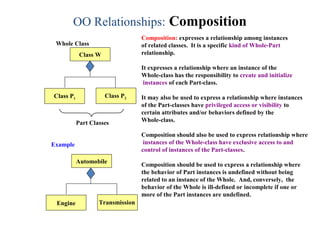
  • 21. OO Relationships: Composition Class W Class P1 Class P2 Composition: expresses a relationship among instances of related classes. It is a specific kind of Whole-Part relationship. It expresses a relationship where an instance of the Whole-class has the responsibility to create and initialize instances of each Part-class. It may also be used to express a relationship where instances of the Part-classes have privileged access or visibility to certain attributes and/or behaviors defined by the Whole-class. Composition should also be used to express relationship where instances of the Whole-class have exclusive access to and control of instances of the Part-classes. Composition should be used to express a relationship where the behavior of Part instances is undefined without being related to an instance of the Whole. And, conversely, the behavior of the Whole is ill-defined or incomplete if one or more of the Part instances are undefined. Whole Class Part Classes Automobile Engine Transmission Example
  • 22. OO Relationships: Aggregation Class C Class E1 Class E2 AGGREGATION Aggregation: expresses a relationship among instances of related classes. It is a specific kind of Container- Containee relationship. It expresses a relationship where an instance of the Container-class has the responsibility to hold and maintain instances of each Containee-class that have been created outside the auspices of the Container-class. Aggregation should be used to express a more informal relationship than composition expresses. That is, it is an appropriate relationship where the Container and its Containees can be manipulated independently. Aggregation is appropriate when Container and Containees have no special access privileges to each other. Container Class Containee Classes Bag Apples Milk Example
  • 23. Aggregation vs. Composition •CompositionComposition is really a strong form of aggregation •components have only one owner •components cannot exist independent of their owner •components live or die with their owner e.g. Each car has an engine that can not be shared with other cars. •Aggregations may form "part of" the aggregate, but may not be essential to it. They may also exist independent of the aggregate. e.g. Apples may exist independent of the bag.
  • 24. Class Diagram Example Hotel Management System
  • 25. Activity Diagram • Procedural flow of control between two or more class objects • Activities are grouped into swim lanes. • Activity is modeled by drawing a rectangle with rounded edges, enclosing the activity's name. • Connected to other activities through transition lines • Activities that terminate the modeled process are connected to a termination point
  • 26. Activity diagram, with two swim lanes to indicate control of activity by two objects: the band manager, and the reporting tool
  • 27. Sequence Diagram • Two dimensional • Vertical dimension shows sequence of messages in the time order that they occur. • Horizontal dimension shows the object instances to which the messages are sent. • Self-Call can also be there in which a message that an object sends to itself.
  • 28. Sequence Diagram(make a phone call) Caller Phone Recipient Picks up Dial tone Dial Ring notification Ring Picks up Hello
  • 29. Sequence Diagrams – Object Life Spans • Creation – Create message – Object life starts at that point • Activation – Symbolized by rectangular stripes – Place on the lifeline where object is activated. – Rectangle also denotes when object is deactivated. • Deletion – Placing an ‘X’ on lifeline – Object’s life ends at that point Activation bar A B Create X Deletion Return Lifeline
  • 30. Sequence Diagram User Catalog Reservations 1: look up () 2: title data () 3: [not available] reserve title () 4 : title returned () 5: hold title () 5 : title available () 6 : borrow title () 6 : remove reservation () Issuing a book from library
  • 31. Collaboration Diagram • Shows the relationship between objects and the order of messages passed between them. • The objects are listed as rectangles and arrows indicate the messages being passed • Convey the same information as sequence diagrams, but focus on object roles instead of the time sequence.
  • 32. Collaboration diagrams of earlier made sequence diagram of issuing of book from library User Catalog Reservations start 1: look up 2: title data 3 : [not available] reserve title 4 : title returned 5 : hold title 6 : borrow title 6: remove reservation 5: title available
  • 33. State Diagrams State Diagrams show the sequences of states an object goes through during its life cycle in response to stimuli, together with its responses and actions; an abstraction of all possible behaviors. Unpaid Start End Paid Invoice created paying Invoice destroying (Billing Example)
  • 34. Deployment Diagram • System will be physically deployed in the hardware environment • System's production staff makes its considerable use • Purpose is to show where the different components of the system will physically run and how they will communicate with each other
  • 36. UML Modeling Tools • Rational Rose (www.rational.com) by IBM • TogetherSoft Control Center, Borland ( http://www.borland.com/together/index.html) • ArgoUML (free software) (http://argouml.tigris.org/ ) OpenSource; written in javawritten in java • Others (http://www.objectsbydesign.com/tools/umltools_byCompany.html )