SlideShare a Scribd company logo
2.3 Build sequential
    logic circuit
      Combinational logic circuit
        Sequential logic circuit
               Flip-flop
    Build flip-flop using logic gates
                                        1
Objectives:
•
1 Define sequential logic circuit.
•
2 Differentiate between combinational logic circuit and
   sequential logic circuit.
•
3 Describe flip - flop.
•
4 Identify various types of flip-flops.
•
5 Build SR, JK, T and D flip – flop using logic gates.
•
6 Draw the symbol and truth table of SR, JK, T and D flip
   – flop.

                                                            2
Sequential & Combinational
                 logic circuit
1 Define sequential logic circuit.
2 Differentiate between combinational logic circuit and
  sequential logic circuit.


                                                          3
Difference between
Combinational & Sequential logic circuit

 Combinational Logic Circuits

 Basic building
 blocks include:

 Sequential Logic Circuits

  Basic building blocks
  include FLIP-FLOPS:
                                    4
Sequential                   S
                                            C
                                                       Q


                 logic circuit             R           Q'


• Sequential logic is the type of digital system
  that does not only depend on current input, but
  also the previous history of the system.
• For that reason sequential logic requires
  memory elements to function.
• The building blocks used to construct devices
  that store data are called flip-flops.

                                                   5
Sequential logic circuit


      Sequential circuit have loops
– these enable curcuits to receive feedback   6
Combinational
               logic circuit
• Combinational logic is an interconnection of
 logic gates to generate a specificities logic
 function where the inputs result in an
 immediate output, having no memory or
 storage capabilities.
• There are function only based on their
 inputs, and NOT based on clocks.


                                             7
Combinational logic circuit


Combinational circuit is combination
      of various logic gates           8
Flip-Flop

3 Describe flip - flop.


                            9
Flip-Flop

• "Flip-flop" is the common name given to two-state
  devices which offer basic memory for sequential
  logic operations.
• Flip-flops are heavily used for digital data storage and
  transfer and are commonly used in banks called
  "registers" for the storage of binary numerical
  data.


                                                         10
Flip-Flop
• Flip-flop are basic storage/memory elements.
• Flip-flop are essentially 1-bit storage devices.
• Types of flip-flops are:
   • 1. SR Flip-flop
   • 2. JK Flip-flop
   • 3. D Flip-flop
   • 4. T Flip-flop
• Application of flip-flop:
   • 1. Counter        4. Logic controller
   • 2. Register       5. Frequency Divider
   • 3. Memory
                                                     11
SR Flip-Flop

4 Identify various types of flip-flops.
5 Build SR, JK, T and D flip – flop using logic gates.
6 Draw the symbol and truth table of SR, JK, T and D flip
  – flop.


                                                            12
SR Flip-Flop                       S          Q

                                                 R          Q'


• The simplest binary storage device.
• SR Flip-flop have 2 inputs (SET & RESET) and 2
  outputs (Q & Q’).
   NOTE: Q & Q’ are compliments of each other

• The SR flip flop is sometimes referred to as an SR
  latch. The Term latch refers to its use as a
  temporary memory storage device.

                                                       13
SR Flip-Flop
                  Symbol:


SR Flip-flop (Active HIGH)   SR Flip-flop (Active HIGH)
     NOR gate                      Symbol
                                                          14
SR Flip-Flop
                  Symbol:


SR Flip-flop (Active LOW)   SR Flip-flop (Active LOW)
   NAND gate                      Symbol
                                                        15
SR Flip-Flop
                    Truth Table:
S    R    Q    Q'
                       No change. Latch             S             Q
0    0    NC   NC
                    remained in present state.
1    0    1    0           Latch SET.               R             Q'
0    1    0    1         Latch RESET.
                                                   SR Flip-flop
1    1    0    0       Invalid condition.        (Active HIGH)


S'   R'   Q    Q'
                       No change. Latch             S             Q
1    1    NC   NC
                    remained in present state.
0    1    1    0           Latch SET.               R             Q'
1    0    0    1         Latch RESET.
                                                   SR Flip-flop
0    0    1    1       Invalid condition.
                                                 (Active LOW)
                                                                       16
SR Flip-Flop
Timing Diagram:


                  17
IQ Test!
 What is the mode of operation of the SR flip-flop (set, reset or hold)?
 What is the output at Q from the SR flip-flop (active LOW inputs)?

        L
                             ?
                             High
        H
                            Mode of operation = Set
                                                 ?


        H
                             ?
                             High
        H
                            Mode of operation = Hold
                                                 ?


        H
                             ?
                             Low
        L
                            Mode of operation =        ?
                                                      Reset          18
Clock
                SR Flip-Flop
4 Identify various types of flip-flops.
5 Build SR, JK, T and D flip – flop using logic gates.
6 Draw the symbol and truth table of SR, JK, T and D flip
  – flop.


                                                            19
Clock
• Flip-flops: synchronous bistable devices
• Output changes state at a specified point on a
  triggering input called the clock.
• Change state either at the positive edge (rising edge) or
  at the negative edge (falling edge) of the clock signal.

                                                Clock signal


           Positive      Negative edges
            edges
                                                             20
Clock
                 SR Flip-Flop
• The Clocked SR Flip Flop like SR flip-flop but with
  extra third input of a standard clock pulse.
• The output of Q and NOT Q will not change
  (despite making changes to the inputs Set & Reset)
  in a Clocked RS Flip-flop Until receiving a signal
  from the clock.


                                                        21
Clock SR Flip-Flop
               Symbol:


Clock SR Flip-flop (+ve EDGE)   Clock SR Flip-flop (+ve EDGE)
Combination gate                        Symbol
                                                         22
S
                                                              Q
                           Pulse
            CLK          transition
                          detector
                                                              Q'
                                      R


                  CLK'                                 CLK'
CLK                           CLK*        CLK                      CLK*


      CLK                                       CLK

      CLK'                                      CLK'

      CLK*                                      CLK*

 Positive-going transition                 Negative-going transition
      (rising edge)                         (falling edge)

                                                                          23
Clock SR Flip-Flop
                 Truth Table:
•   S-R flip-flop: on the triggering edge of the clock pulse,
•   S=HIGH and R=LOW is a SET state
•   R=HIGH (and S=LOW) is a RESET state
•   If both SR inputs LOW a NO change
•   If both SR inputs HIGH a INVALID
•   Truth table of positive edge-triggered S-R flip-flop:

    S    R   CLK       Q(t+1)    Comments
                                                 X = irrelevant (“don’t care”)
    0    0     X        Q(t)     No change        = clock transition LOW to HIGH
    0    1              0       Reset
    1    0              1       Set
    1    1              ?       Invalid
                                                                             24
Clock SR Flip-Flop
    Timing Diagram:


How if we add clock as input?
    Please draw the output waveform for me
            (Positive edge triggered)
                                             25
D Flip-Flop
4 Identify various types of flip-flops.
5 Build SR, JK, T and D flip – flop using logic gates.
6 Draw the symbol and truth table of SR, JK, T and D flip
  – flop.


                                                            26
D Flip-Flop                               D            Q

                      Truth Table:
                                                                     C
                                                                              Q'


•       D flip-flop: single input D (data)
•       D=HIGH a SET state
•       D=LOW a RESET state
•       Q follows D at the clock edge.
•       D flip-flop formed by add NOT gate between SR input.

    D            S         Q     D   CLK     Q(t+1)   Comments
CLK               C              1             1     Set
                 R         Q'    0             0     Reset

                                   = clock transition LOW to HIGH
                                                                         27
D Flip-Flop
                       Symbol:

      D
                               Q
CLK
                               Q'


      D Flip-flop (+ve EDGE)        D Flip-flop (+ve EDGE)
 Combination gate                       Symbol
                                                             28
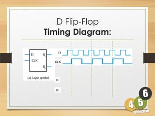
D Flip-Flop
      Timing Diagram:


CLK
CLK     CLK
        CLK


        Q


        Q’


                        29
JK Flip-Flop

4 Identify various types of flip-flops.
5 Build SR, JK, T and D flip – flop using logic gates.
6 Draw the symbol and truth table of SR, JK, T and D flip
  – flop.


                                                            30
JK Flip-Flop                       J
                                                   C
                                                            Q


                                                  K         Q'


• J-K flip-flop: Q and Q' are feedback to the pulse-
  steering NAND gates.
• No invalid state.
• Include a toggle state.
    • J=HIGH (and K=LOW) a SET state
    • K=HIGH (and J=LOW) a RESET state
    • If both inputs LOW a NO change
    • If both inputs HIGH a Toggle
                                                       31
JK Flip-Flop
                       Symbol:

  J
                                Q

CLK

                                Q'
  K


      JK Flip-flop (+ve EDGE)        JK Flip-flop (+ve EDGE)
 Combination gate                         Symbol
                                                           32
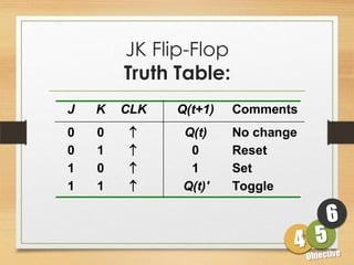
JK Flip-Flop
        Truth Table:
J   K   CLK   Q(t+1)   Comments
0   0        Q(t)     No change
0   1         0       Reset
1   0         1       Set
1   1        Q(t)'    Toggle


                                   33
JK Flip-Flop
        Application: Frequency Division

            High                      High             High

                   J                         J    QA          J        QB
                         Q
      CLK          C            CLK          C                C

                   K                         K                K


CLK                                   CLK

 Q                                    QA

                                      QB

 Divide clock frequency by 2.          Divide clock frequency by 4.
                                                                  34
JK Flip-Flop
             Timing Diagram:
Similar to S-R flip-flop but toggles when J = K = 1


                                                      35
T Flip-Flop

4 Identify various types of flip-flops.
5 Build SR, JK, T and D flip – flop using logic gates.
6 Draw the symbol and truth table of SR, JK, T and D flip
  – flop.


                                                            36
T Flip-Flop                  T       J           Q

                    Truth Table:
                                                CLK        C
                                                          K           Q'


    • T flip-flop: single-input version of the J-K flip
      flop, formed by tying both inputs together.


T                                     T   CLK    Q(t+1)   Comments
                               Q
                                      0          Q(t)    No change
       CLK                            1          Q(t)'   Toggle
                               Q'


                                                               37

More Related Content

What's hot (20)

PPTX
Race around and master slave flip flop
Shubham Singh
 
PPTX
Digital clock (mod counters)using DSCH (DIGITAL SCHEMATIC) by Gaurav Raikar
GauravRaikar3
 
PDF
Cmos logic
Revathi Subramaniam
 
PPTX
Flip Flop & RS Latch
university of education,Lahore
 
PPTX
Counters
Ketaki_Pattani
 
PPTX
Flip flop
Moni Adhikary
 
PPTX
Sequential logic circuits flip-flop pt 1
Sarah Sue Calbio
 
PDF
Flip flop
JAGMIT Jamkhandi
 
PPTX
Monte carlo analysis
GargiKhanna1
 
PPT
Flipflops JK T SR D All FlipFlop Slides
Sid Rehmani
 
PDF
Ripple counter
chandkec
 
PPTX
JK flip flop in Digital electronics
Easy n Inspire L
 
PPTX
Decoders-Digital Electronics
Paurav Shah
 
PPTX
SEQUENTIAL CIRCUITS [Flip-flops and Latches]
Electronics for Biomedical
 
PDF
Ring counter
Ghufran Hasan
 
PPTX
Registers
UMARHASSAN31
 
PPTX
Unit v memory & programmable logic devices
KanmaniRajamanickam
 
PPTX
Johnson counter
Muhammad Anas Sabir
 
PPTX
Clock divider by 3
Ashok Reddy
 
PPTX
flip flop circuits and its applications
Gaditek
 
Race around and master slave flip flop
Shubham Singh
 
Digital clock (mod counters)using DSCH (DIGITAL SCHEMATIC) by Gaurav Raikar
GauravRaikar3
 
Flip Flop & RS Latch
university of education,Lahore
 
Counters
Ketaki_Pattani
 
Flip flop
Moni Adhikary
 
Sequential logic circuits flip-flop pt 1
Sarah Sue Calbio
 
Flip flop
JAGMIT Jamkhandi
 
Monte carlo analysis
GargiKhanna1
 
Flipflops JK T SR D All FlipFlop Slides
Sid Rehmani
 
Ripple counter
chandkec
 
JK flip flop in Digital electronics
Easy n Inspire L
 
Decoders-Digital Electronics
Paurav Shah
 
SEQUENTIAL CIRCUITS [Flip-flops and Latches]
Electronics for Biomedical
 
Ring counter
Ghufran Hasan
 
Registers
UMARHASSAN31
 
Unit v memory & programmable logic devices
KanmaniRajamanickam
 
Johnson counter
Muhammad Anas Sabir
 
Clock divider by 3
Ashok Reddy
 
flip flop circuits and its applications
Gaditek
 

Viewers also liked (16)

PDF
Sequential logic circuits flip-flop pt 3
Sarah Sue Calbio
 
PDF
Chapter 4 flip flop for students
CT Sabariah Salihin
 
PDF
Sequential circuits in digital logic design
Nallapati Anindra
 
PPT
Sequential Logic Circuit
Ramasubbu .P
 
PPTX
Sequential Logic Circuit
Yong Heui Cho
 
PPT
Computer Oragnization Flipflops
Vanitha Chandru
 
PPTX
Logic gates - AND, OR, NOT, NOR, NAND, XOR, XNOR Gates.
Satya P. Joshi
 
PDF
Chapter 5 counter
CT Sabariah Salihin
 
PPT
Semiconductor
Yong Heui Cho
 
PPTX
Combinational Logic Circuit
Yong Heui Cho
 
PPT
Digital 9 16
Sayan Chakraborty
 
PDF
CMOS Topic 6 -_designing_combinational_logic_circuits
Ikhwan_Fakrudin
 
PPTX
Flip flops (ff)
Arturo Guillén
 
PPT
14827 shift registers
Sandeep Kumar
 
PPTX
Overview of Shift register and applications
Karthik Kumar
 
PDF
Primary Programs Framework - Curriculum Integration: Making Connections
Sarah Sue Calbio
 
Sequential logic circuits flip-flop pt 3
Sarah Sue Calbio
 
Chapter 4 flip flop for students
CT Sabariah Salihin
 
Sequential circuits in digital logic design
Nallapati Anindra
 
Sequential Logic Circuit
Ramasubbu .P
 
Sequential Logic Circuit
Yong Heui Cho
 
Computer Oragnization Flipflops
Vanitha Chandru
 
Logic gates - AND, OR, NOT, NOR, NAND, XOR, XNOR Gates.
Satya P. Joshi
 
Chapter 5 counter
CT Sabariah Salihin
 
Semiconductor
Yong Heui Cho
 
Combinational Logic Circuit
Yong Heui Cho
 
Digital 9 16
Sayan Chakraborty
 
CMOS Topic 6 -_designing_combinational_logic_circuits
Ikhwan_Fakrudin
 
Flip flops (ff)
Arturo Guillén
 
14827 shift registers
Sandeep Kumar
 
Overview of Shift register and applications
Karthik Kumar
 
Primary Programs Framework - Curriculum Integration: Making Connections
Sarah Sue Calbio
 
Ad

Similar to 2.3 sequantial logic circuit (20)

PPTX
Flipflop
sohamdodia27
 
PPTX
Flipflopsupdated explanation and applications.pptx
amandavid6969
 
PPT
Unit 4 clocked_flip_flops
UNAD
 
PPT
Sequential circuit
Brenda Debra
 
PPTX
Flip flop
AttaRahmanQureshi
 
PPT
14827 unit 4_clocked_flip_flops
Sandeep Kumar
 
PPTX
ABOUT FLIP FLOPS IN DIGITAL ELECTRONICS .pptx
ropide1272
 
PPTX
SEQUENTIAL LOGIC CIRCUITS (FLIP FLOPS AND LATCHES)
Sairam Adithya
 
PPT
flip-flop1.ppt
profabhishekranjan
 
PPTX
Flip flop
Bhaskar Kumar Jha
 
PPT
Digital-logic-design-16148_flip-flop1.ppt
SherifElGohary7
 
PPTX
SEQUENTIAL CIRCUITS [FLIP FLOPS AND LATCHES]
SUBHA SHREE
 
PPTX
flip flops
Unsa Shakir
 
PPTX
dldflip-flop-151229031138 (1).pptx
Kumar290483
 
PDF
Flip-flops, Shift Registers and Counters.pdf
SandeepR330988
 
PPTX
Bistables-multivibrators .pptx
Rethabile37
 
PDF
Flipflop for Electronics and Communication Engineering students.pdf
izukumido
 
PPTX
Latch and Flipflop.pptx
ramkumarraja7
 
PPTX
UNIT - III.pptx
amudhak10
 
PPTX
Chapter 6: Sequential Logic
Er. Nawaraj Bhandari
 
Flipflop
sohamdodia27
 
Flipflopsupdated explanation and applications.pptx
amandavid6969
 
Unit 4 clocked_flip_flops
UNAD
 
Sequential circuit
Brenda Debra
 
Flip flop
AttaRahmanQureshi
 
14827 unit 4_clocked_flip_flops
Sandeep Kumar
 
ABOUT FLIP FLOPS IN DIGITAL ELECTRONICS .pptx
ropide1272
 
SEQUENTIAL LOGIC CIRCUITS (FLIP FLOPS AND LATCHES)
Sairam Adithya
 
flip-flop1.ppt
profabhishekranjan
 
Digital-logic-design-16148_flip-flop1.ppt
SherifElGohary7
 
SEQUENTIAL CIRCUITS [FLIP FLOPS AND LATCHES]
SUBHA SHREE
 
flip flops
Unsa Shakir
 
dldflip-flop-151229031138 (1).pptx
Kumar290483
 
Flip-flops, Shift Registers and Counters.pdf
SandeepR330988
 
Bistables-multivibrators .pptx
Rethabile37
 
Flipflop for Electronics and Communication Engineering students.pdf
izukumido
 
Latch and Flipflop.pptx
ramkumarraja7
 
UNIT - III.pptx
amudhak10
 
Chapter 6: Sequential Logic
Er. Nawaraj Bhandari
 
Ad

Recently uploaded (20)

PPTX
Urban Hierarchy and Service Provisions.pptx
Islamic University of Bangladesh
 
PPTX
ESP 10 Edukasyon sa Pagpapakatao PowerPoint Lessons Quarter 1.pptx
Sir J.
 
PPTX
How to Create & Manage Stages in Odoo 18 Helpdesk
Celine George
 
PPTX
Practice Gardens and Polytechnic Education: Utilizing Nature in 1950s’ Hu...
Lajos Somogyvári
 
PDF
Andreas Schleicher_Teaching Compass_Education 2040.pdf
EduSkills OECD
 
PPTX
PLANNING A HOSPITAL AND NURSING UNIT.pptx
PRADEEP ABOTHU
 
PDF
The Power of Compound Interest (Stanford Initiative for Financial Decision-Ma...
Stanford IFDM
 
PPTX
week 1-2.pptx yueojerjdeiwmwjsweuwikwswiewjrwiwkw
rebznelz
 
PPTX
How Physics Enhances Our Quality of Life.pptx
AngeliqueTolentinoDe
 
PPTX
Connecting Linear and Angular Quantities in Human Movement.pptx
AngeliqueTolentinoDe
 
PDF
TLE 8 QUARTER 1 MODULE WEEK 1 MATATAG CURRICULUM
denniseraya1997
 
PDF
Supply Chain Security A Comprehensive Approach 1st Edition Arthur G. Arway
rxgnika452
 
PPTX
How to Add a Custom Button in Odoo 18 POS Screen
Celine George
 
PPTX
PLANNING FOR EMERGENCY AND DISASTER MANAGEMENT ppt.pptx
PRADEEP ABOTHU
 
PPTX
Parsing HTML read and write operations and OS Module.pptx
Ramakrishna Reddy Bijjam
 
PDF
Indian National movement PPT by Simanchala Sarab, Covering The INC(Formation,...
Simanchala Sarab, BABed(ITEP Secondary stage) in History student at GNDU Amritsar
 
PPTX
SYMPATHOMIMETICS[ADRENERGIC AGONISTS] pptx
saip95568
 
PDF
DIGESTION OF CARBOHYDRATES ,PROTEINS AND LIPIDS
raviralanaresh2
 
PDF
Rapid Mathematics Assessment Score sheet for all Grade levels
DessaCletSantos
 
PDF
Our Guide to the July 2025 USPS® Rate Change
Postal Advocate Inc.
 
Urban Hierarchy and Service Provisions.pptx
Islamic University of Bangladesh
 
ESP 10 Edukasyon sa Pagpapakatao PowerPoint Lessons Quarter 1.pptx
Sir J.
 
How to Create & Manage Stages in Odoo 18 Helpdesk
Celine George
 
Practice Gardens and Polytechnic Education: Utilizing Nature in 1950s’ Hu...
Lajos Somogyvári
 
Andreas Schleicher_Teaching Compass_Education 2040.pdf
EduSkills OECD
 
PLANNING A HOSPITAL AND NURSING UNIT.pptx
PRADEEP ABOTHU
 
The Power of Compound Interest (Stanford Initiative for Financial Decision-Ma...
Stanford IFDM
 
week 1-2.pptx yueojerjdeiwmwjsweuwikwswiewjrwiwkw
rebznelz
 
How Physics Enhances Our Quality of Life.pptx
AngeliqueTolentinoDe
 
Connecting Linear and Angular Quantities in Human Movement.pptx
AngeliqueTolentinoDe
 
TLE 8 QUARTER 1 MODULE WEEK 1 MATATAG CURRICULUM
denniseraya1997
 
Supply Chain Security A Comprehensive Approach 1st Edition Arthur G. Arway
rxgnika452
 
How to Add a Custom Button in Odoo 18 POS Screen
Celine George
 
PLANNING FOR EMERGENCY AND DISASTER MANAGEMENT ppt.pptx
PRADEEP ABOTHU
 
Parsing HTML read and write operations and OS Module.pptx
Ramakrishna Reddy Bijjam
 
Indian National movement PPT by Simanchala Sarab, Covering The INC(Formation,...
Simanchala Sarab, BABed(ITEP Secondary stage) in History student at GNDU Amritsar
 
SYMPATHOMIMETICS[ADRENERGIC AGONISTS] pptx
saip95568
 
DIGESTION OF CARBOHYDRATES ,PROTEINS AND LIPIDS
raviralanaresh2
 
Rapid Mathematics Assessment Score sheet for all Grade levels
DessaCletSantos
 
Our Guide to the July 2025 USPS® Rate Change
Postal Advocate Inc.
 

2.3 sequantial logic circuit

  • 1. 2.3 Build sequential logic circuit Combinational logic circuit Sequential logic circuit Flip-flop Build flip-flop using logic gates 1
  • 2. Objectives: • 1 Define sequential logic circuit. • 2 Differentiate between combinational logic circuit and sequential logic circuit. • 3 Describe flip - flop. • 4 Identify various types of flip-flops. • 5 Build SR, JK, T and D flip – flop using logic gates. • 6 Draw the symbol and truth table of SR, JK, T and D flip – flop. 2
  • 3. Sequential & Combinational logic circuit 1 Define sequential logic circuit. 2 Differentiate between combinational logic circuit and sequential logic circuit. 3
  • 4. Difference between Combinational & Sequential logic circuit Combinational Logic Circuits Basic building blocks include: Sequential Logic Circuits Basic building blocks include FLIP-FLOPS: 4
  • 5. Sequential S C Q logic circuit R Q' • Sequential logic is the type of digital system that does not only depend on current input, but also the previous history of the system. • For that reason sequential logic requires memory elements to function. • The building blocks used to construct devices that store data are called flip-flops. 5
  • 6. Sequential logic circuit Sequential circuit have loops – these enable curcuits to receive feedback 6
  • 7. Combinational logic circuit • Combinational logic is an interconnection of logic gates to generate a specificities logic function where the inputs result in an immediate output, having no memory or storage capabilities. • There are function only based on their inputs, and NOT based on clocks. 7
  • 8. Combinational logic circuit Combinational circuit is combination of various logic gates 8
  • 10. Flip-Flop • "Flip-flop" is the common name given to two-state devices which offer basic memory for sequential logic operations. • Flip-flops are heavily used for digital data storage and transfer and are commonly used in banks called "registers" for the storage of binary numerical data. 10
  • 11. Flip-Flop • Flip-flop are basic storage/memory elements. • Flip-flop are essentially 1-bit storage devices. • Types of flip-flops are: • 1. SR Flip-flop • 2. JK Flip-flop • 3. D Flip-flop • 4. T Flip-flop • Application of flip-flop: • 1. Counter 4. Logic controller • 2. Register 5. Frequency Divider • 3. Memory 11
  • 12. SR Flip-Flop 4 Identify various types of flip-flops. 5 Build SR, JK, T and D flip – flop using logic gates. 6 Draw the symbol and truth table of SR, JK, T and D flip – flop. 12
  • 13. SR Flip-Flop S Q R Q' • The simplest binary storage device. • SR Flip-flop have 2 inputs (SET & RESET) and 2 outputs (Q & Q’). NOTE: Q & Q’ are compliments of each other • The SR flip flop is sometimes referred to as an SR latch. The Term latch refers to its use as a temporary memory storage device. 13
  • 14. SR Flip-Flop Symbol: SR Flip-flop (Active HIGH) SR Flip-flop (Active HIGH) NOR gate Symbol 14
  • 15. SR Flip-Flop Symbol: SR Flip-flop (Active LOW) SR Flip-flop (Active LOW) NAND gate Symbol 15
  • 16. SR Flip-Flop Truth Table: S R Q Q' No change. Latch S Q 0 0 NC NC remained in present state. 1 0 1 0 Latch SET. R Q' 0 1 0 1 Latch RESET. SR Flip-flop 1 1 0 0 Invalid condition. (Active HIGH) S' R' Q Q' No change. Latch S Q 1 1 NC NC remained in present state. 0 1 1 0 Latch SET. R Q' 1 0 0 1 Latch RESET. SR Flip-flop 0 0 1 1 Invalid condition. (Active LOW) 16
  • 18. IQ Test! What is the mode of operation of the SR flip-flop (set, reset or hold)? What is the output at Q from the SR flip-flop (active LOW inputs)? L ? High H Mode of operation = Set ? H ? High H Mode of operation = Hold ? H ? Low L Mode of operation = ? Reset 18
  • 19. Clock SR Flip-Flop 4 Identify various types of flip-flops. 5 Build SR, JK, T and D flip – flop using logic gates. 6 Draw the symbol and truth table of SR, JK, T and D flip – flop. 19
  • 20. Clock • Flip-flops: synchronous bistable devices • Output changes state at a specified point on a triggering input called the clock. • Change state either at the positive edge (rising edge) or at the negative edge (falling edge) of the clock signal. Clock signal Positive Negative edges edges 20
  • 21. Clock SR Flip-Flop • The Clocked SR Flip Flop like SR flip-flop but with extra third input of a standard clock pulse. • The output of Q and NOT Q will not change (despite making changes to the inputs Set & Reset) in a Clocked RS Flip-flop Until receiving a signal from the clock. 21
  • 22. Clock SR Flip-Flop Symbol: Clock SR Flip-flop (+ve EDGE) Clock SR Flip-flop (+ve EDGE) Combination gate Symbol 22
  • 23. S Q Pulse CLK transition detector Q' R CLK' CLK' CLK CLK* CLK CLK* CLK CLK CLK' CLK' CLK* CLK* Positive-going transition Negative-going transition (rising edge) (falling edge) 23
  • 24. Clock SR Flip-Flop Truth Table: • S-R flip-flop: on the triggering edge of the clock pulse, • S=HIGH and R=LOW is a SET state • R=HIGH (and S=LOW) is a RESET state • If both SR inputs LOW a NO change • If both SR inputs HIGH a INVALID • Truth table of positive edge-triggered S-R flip-flop: S R CLK Q(t+1) Comments X = irrelevant (“don’t care”) 0 0 X Q(t) No change  = clock transition LOW to HIGH 0 1  0 Reset 1 0  1 Set 1 1  ? Invalid 24
  • 25. Clock SR Flip-Flop Timing Diagram: How if we add clock as input? Please draw the output waveform for me (Positive edge triggered) 25
  • 26. D Flip-Flop 4 Identify various types of flip-flops. 5 Build SR, JK, T and D flip – flop using logic gates. 6 Draw the symbol and truth table of SR, JK, T and D flip – flop. 26
  • 27. D Flip-Flop D Q Truth Table: C Q' • D flip-flop: single input D (data) • D=HIGH a SET state • D=LOW a RESET state • Q follows D at the clock edge. • D flip-flop formed by add NOT gate between SR input. D S Q D CLK Q(t+1) Comments CLK C 1  1 Set R Q' 0  0 Reset  = clock transition LOW to HIGH 27
  • 28. D Flip-Flop Symbol: D Q CLK Q' D Flip-flop (+ve EDGE) D Flip-flop (+ve EDGE) Combination gate Symbol 28
  • 29. D Flip-Flop Timing Diagram: CLK CLK CLK CLK Q Q’ 29
  • 30. JK Flip-Flop 4 Identify various types of flip-flops. 5 Build SR, JK, T and D flip – flop using logic gates. 6 Draw the symbol and truth table of SR, JK, T and D flip – flop. 30
  • 31. JK Flip-Flop J C Q K Q' • J-K flip-flop: Q and Q' are feedback to the pulse- steering NAND gates. • No invalid state. • Include a toggle state. • J=HIGH (and K=LOW) a SET state • K=HIGH (and J=LOW) a RESET state • If both inputs LOW a NO change • If both inputs HIGH a Toggle 31
  • 32. JK Flip-Flop Symbol: J Q CLK Q' K JK Flip-flop (+ve EDGE) JK Flip-flop (+ve EDGE) Combination gate Symbol 32
  • 33. JK Flip-Flop Truth Table: J K CLK Q(t+1) Comments 0 0  Q(t) No change 0 1  0 Reset 1 0  1 Set 1 1  Q(t)' Toggle 33
  • 34. JK Flip-Flop Application: Frequency Division High High High J J QA J QB Q CLK C CLK C C K K K CLK CLK Q QA QB Divide clock frequency by 2. Divide clock frequency by 4. 34
  • 35. JK Flip-Flop Timing Diagram: Similar to S-R flip-flop but toggles when J = K = 1 35
  • 36. T Flip-Flop 4 Identify various types of flip-flops. 5 Build SR, JK, T and D flip – flop using logic gates. 6 Draw the symbol and truth table of SR, JK, T and D flip – flop. 36
  • 37. T Flip-Flop T J Q Truth Table: CLK C K Q' • T flip-flop: single-input version of the J-K flip flop, formed by tying both inputs together. T T CLK Q(t+1) Comments Q 0  Q(t) No change CLK 1  Q(t)' Toggle Q' 37