SlideShare a Scribd company logo
Chapter 3
Boolean Algebra and
Digital Logic
12
3.2 Boolean Algebra
• Most Boolean identities have an AND (product)
form as well as an OR (sum) form. We give our
identities using both forms. Our first group is rather
intuitive:
13
3.2 Boolean Algebra
• Idempotence is the property of certain operations
in mathematics and computer science that they can
be applied multiple times without changing the
result beyond the initial application.
14
3.2 Boolean Algebra
• Our second group of Boolean identities should be
familiar to you from your study of algebra:
15
3.2 Boolean Algebra
• Our last group of Boolean identities are perhaps the
most useful.
• If you have studied set theory or formal logic, these
laws are also familiar to you.
16
3.2 Boolean Algebra
• De Morgan's Law -
not (A or B) = not A and not B;
not (A and B) = not A or not B
• Absorption Law
a ^ (a v b)=a v (a ^ b)=a
17
3.2 Boolean Algebra
• We can use Boolean identities to simplify the
function:
as follows:
18
3.2 Boolean Algebra
• Sometimes it is more economical to build a
circuit using the complement of a function (and
complementing its result) than it is to implement
the function directly.
• DeMorgan’s law provides an easy way of finding
the complement of a Boolean function.
• Recall DeMorgan’s law states:
19
3.2 Boolean Algebra
• DeMorgan’s law can be extended to any number of
variables.
• Replace each variable by its complement and
change all ANDs to ORs and all ORs to ANDs.
• Thus, we find the the complement of:
is:
20
3.2 Boolean Algebra
• Through our exercises in simplifying Boolean
expressions, we see that there are numerous
ways of stating the same Boolean expression.
– These “synonymous” forms are logically equivalent.
– Logically equivalent expressions have identical truth
tables.
• In order to eliminate as much confusion as
possible, designers express Boolean functions in
standardized or canonical form.
21
3.2 Boolean Algebra
• There are two canonical forms for Boolean
expressions: sum-of-products and product-of-sums.
– Recall the Boolean product is the AND operation and the
Boolean sum is the OR operation.
• In the sum-of-products form, ANDed variables are
ORed together.
– For example:
• In the product-of-sums form, ORed variables are
ANDed together:
– For example:
22
3.2 Boolean Algebra
• It is easy to convert a function
to sum-of-products form using
its truth table.
• We are interested in the values
of the variables that make the
function true (=1).
• Using the truth table, we list
the values of the variables that
result in a true function value.
• Each group of variables is then
ORed together.
23
3.2 Boolean Algebra
• The sum-of-products form
for our function is:
We note that this function is not
in simplest terms. Our aim is
only to rewrite our function in
canonical sum-of-products form.
24
• We have looked at Boolean functions in abstract
terms.
• In this section, we see that Boolean functions are
implemented in digital computer circuits called gates.
• A gate is an electronic device that produces a result
based on two or more input values.
– In reality, gates consist of one to six transistors, but digital
designers think of them as a single unit.
– Integrated circuits contain collections of gates suited to a
particular purpose.
3.3 Logic Gates
25
• The three simplest gates are the AND, OR, and NOT
gates.
• They correspond directly to their respective Boolean
operations, as you can see by their truth tables.
3.3 Logic Gates
26
• Another very useful gate is the exclusive OR
(XOR) gate.
• The output of the XOR operation is true only when
the values of the inputs differ.
3.3 Logic Gates
Note the special symbol 
for the XOR operation.
27
• NAND and NOR
are two very
important gates.
Their symbols and
truth tables are
shown at the right.
3.3 Logic Gates
28
3.3 Logic Gates
• NAND and NOR
are known as
universal gates
because they are
inexpensive to
manufacture and
any Boolean
function can be
constructed using
only NAND or only
NOR gates.
29
3.3 Logic Gates
• Gates can have multiple inputs and more than
one output.
– A second output can be provided for the complement
of the operation.
– We’ll see more of this later.
30
3.4 Digital Components
• The main thing to remember is that combinations
of gates implement Boolean functions.
• The circuit below implements the Boolean
function:
We simplify our Boolean expressions so
that we can create simpler circuits.
31
3.5 Combinational Circuits
• We have designed a circuit that implements the
Boolean function:
• This circuit is an example of a combinational logic
circuit.
• Combinational logic circuits produce a specified
output (almost) at the instant when input values
are applied.
– In a later section, we will explore circuits where this is
not the case.
32
3.5 Combinational Circuits
• Combinational logic circuits
give us many useful devices.
• One of the simplest is the
half adder, which finds the
sum of two bits.
• We can gain some insight as
to the construction of a half
adder by looking at its truth
table, shown at the right.
33
3.5 Combinational Circuits
• As we see, the sum can be
found using the XOR
operation and the carry
using the AND operation.
34
3.5 Combinational Circuits
• We can change our half
adder into to a full adder
by including gates for
processing the carry bit.
• The truth table for a full
adder is shown at the
right.
35
3.5 Combinational Circuits
• How can we change the
half adder shown below
to make it a full adder?
36
3.5 Combinational Circuits
• Here’s our completed full adder.
37
3.5 Combinational Circuits
• Just as we combined half adders to make a full
adder, full adders can connected in series.
• The carry bit “ripples” from one adder to the next;
hence, this configuration is called a ripple-carry
adder.
Today’s systems employ more efficient adders.
38
3.5 Combinational Circuits
• Decoders are another important type of
combinational circuit.
• Among other things, they are useful in selecting a
memory location according a binary value placed
on the address lines of a memory bus.
• Address decoders with n inputs can select any of 2n
locations.
This is a block
diagram for a
decoder.
39
3.5 Combinational Circuits
• This is what a 2-to-4 decoder looks like on the
inside.
If x = 0 and y = 1,
which output line
is enabled?
40
3.5 Combinational Circuits
• A multiplexer does just the
opposite of a decoder.
• It selects a single output
from several inputs.
• The particular input chosen
for output is determined by
the value of the multiplexer’s
control lines.
• To be able to select among n
inputs, log2n control lines are
needed.
This is a block
diagram for a
multiplexer.
41
3.5 Combinational Circuits
• This is what a 4-to-1 multiplexer looks like on the
inside.
If S0 = 1 and S1 = 0,
which input is
transferred to the
output?
42
3.5 Combinational Circuits
• This shifter
moves the
bits of a
nibble one
position to the
left or right.
If S = 0, in which
direction do the
input bits shift?
43
3.6 Sequential Circuits
• Combinational logic circuits are perfect for
situations when we require the immediate
application of a Boolean function to a set of inputs.
• There are other times, however, when we need a
circuit to change its value with consideration to its
current state as well as its inputs.
– These circuits have to “remember” their current state.
• Sequential logic circuits provide this functionality
for us.
44
3.6 Sequential Circuits
• As the name implies, sequential logic circuits require
a means by which events can be sequenced.
• State changes are controlled by clocks.
– A “clock” is a special circuit that sends electrical pulses
through a circuit.
• Clocks produce electrical waveforms such as the
one shown below.
45
3.6 Sequential Circuits
• State changes occur in sequential circuits only
when the clock ticks.
• Circuits can change state on the rising edge,
falling edge, or when the clock pulse reaches its
highest voltage.
46
3.6 Sequential Circuits
• Circuits that change state on the rising edge, or
falling edge of the clock pulse are called edge-
triggered.
• Level-triggered circuits change state when the
clock voltage reaches its highest or lowest level.
47
3.6 Sequential Circuits
• To retain their state values, sequential circuits rely
on feedback.
• Feedback in digital circuits occurs when an output
is looped back to the input.
• A simple example of this concept is shown below.
– If Q is 0 it will always be 0, if it is 1, it will always be 1.
Why?
48
3.6 Sequential Circuits
• You can see how feedback works by examining
the most basic sequential logic components, the
SR flip-flop.
– The “SR” stands for set/reset.
• The internals of an SR flip-flop are shown below,
along with its block diagram.
49
3.6 Sequential Circuits
• The behavior of an SR flip-flop is described by
a characteristic table.
• Q(t) means the value of the output at time t.
Q(t+1) is the value of Q after the next clock
pulse.
50
3.6 Sequential Circuits
• The SR flip-flop actually
has three inputs: S, R,
and its current output, Q.
• Thus, we can construct
a truth table for this
circuit, as shown at the
right.
• Notice the two undefined
values. When both S
and R are 1, the SR flip-
flop is unstable.
51
3.6 Sequential Circuits
• If we can be sure that the inputs to an SR flip-flop
will never both be 1, we will never have an
unstable circuit. This may not always be the case.
• The SR flip-flop can be modified to provide a
stable state when both inputs are 1.
• This modified flip-flop is
called a JK flip-flop,
shown at the right.
- The “JK” is in honor of
Jack Kilby.
52
3.6 Sequential Circuits
• At the right, we see
how an SR flip-flop
can be modified to
create a JK flip-flop.
• The characteristic
table indicates that
the flip-flop is stable
for all inputs.
53
3.6 Sequential Circuits
• Another modification of the SR flip-flop is the D
flip-flop, shown below with its characteristic table.
• You will notice that the output of the flip-flop
remains the same during subsequent clock
pulses. The output changes only when the value
of D changes.
54
3.6 Sequential Circuits
• The D flip-flop is the fundamental circuit of
computer memory.
– D flip-flops are usually illustrated using the block
diagram shown below.
• The characteristic table for the D flip-flop is
shown at the right.
55
3.6 Sequential Circuits
• The behavior of sequential circuits can be
expressed using characteristic tables or finite state
machines (FSMs).
– FSMs consist of a set of nodes that hold the states of the
machine and a set of arcs that connect the states.
• Moore and Mealy machines are two types of FSMs
that are equivalent.
– They differ only in how they express the outputs of the
machine.
• Moore machines place outputs on each node, while
Mealy machines present their outputs on the
transitions.
56
3.6 Sequential Circuits
• The behavior of a JK flop-flop is depicted below by
a Moore machine (left) and a Mealy machine
(right).
57
3.6 Sequential Circuits
• Although the behavior of Moore and Mealy
machines is identical, their implementations differ.
This is our Moore
machine.
58
3.6 Sequential Circuits
• Although the behavior of Moore and Mealy
machines is identical, their implementations differ.
This is our Mealy
machine.
59
3.6 Sequential Circuits
• It is difficult to express the complexities of actual
implementations using only Moore and Mealy
machines.
– For one thing, they do not address the intricacies of
timing very well.
– Secondly, it is often the case that an interaction of
numerous signals is required to advance a machine from
one state to the next.
• For these reasons, Christopher Clare invented the
algorithmic state machine (ASM).
The next slide illustrates the components of an ASM.
60
3.6 Sequential Circuits
61
3.6 Sequential Circuits
• This is an ASM for a microwave oven.
62
3.6 Sequential Circuits
• Sequential circuits are used anytime that we have
a “stateful” application.
– A stateful application is one where the next state of the
machine depends on the current state of the machine
and the input.
• A stateful application requires both combinational
and sequential logic.
• The following slides provide several examples of
circuits that fall into this category.
Can you think of others?
63
3.6 Sequential Circuits
• This illustration shows a
4-bit register consisting of
D flip-flops. You will
usually see its block
diagram (below) instead.
A larger memory configuration
is shown on the next slide.
64
3.6 Sequential Circuits
65
3.6 Sequential Circuits
• A binary counter is
another example of a
sequential circuit.
• The low-order bit is
complemented at each
clock pulse.
• Whenever it changes
from 0 to 1, the next bit
is complemented, and
so on through the
other flip-flops.
66
3.6 Sequential Circuits
• Convolutional coding and decoding requires
sequential circuits.
• One important convolutional code is the (2,1)
convolutional code that underlies the PRML code
that is briefly described at the end of Chapter 2.
• A (2, 1) convolutional code is so named because
two symbols are output for every one symbol
input.
• A convolutional encoder for PRML with its
characteristic table is shown on the next slide.
67
3.6 Sequential Circuits
68
3.6 Sequential Circuits
This is the Mealy
machine for our encoder.
69
3.6 Sequential Circuits
F(1101 0010) = 11 01 01 00 10 11 11 10.
• The fact that there is a
limited set of possible
state transitions in the
encoding process is
crucial to the error
correcting capabilities of
PRML.
• You can see by our
Mealy machine for
encoding that:
70
3.6 Sequential Circuits
F(11 01 01 00 10 11 11 10) = 1101 0010
• The decoding of our
code is provided by
inverting the inputs and
outputs of the Mealy
machine for the
encoding process.
• You can see by our
Mealy machine for
decoding that:
71
3.6 Sequential Circuits
F(00 10 11 11) = 1001
• Yet another way of
looking at the decoding
process is through a
lattice diagram.
• Here we have plotted
the state transitions
based on the input (top)
and showing the output
at the bottom for the
string 00 10 11 11.
72
3.6 Sequential Circuits
F(00 10 11 11) = 1001
• Suppose we receive
the erroneous string:
10 10 11 11.
• Here we have plotted
the accumulated errors
based on the allowable
transitions.
• The path of least error
outputs 1001, thus
1001 is the string of
maximum likelihood.
73
3.7 Designing Circuits
• We have seen digital circuits from two points of
view: digital analysis and digital synthesis.
– Digital analysis explores the relationship between a
circuits inputs and its outputs.
– Digital synthesis creates logic diagrams using the values
specified in a truth table.
• Digital systems designers must also be mindful of
the physical behaviors of circuits to include minute
propagation delays that occur between the time
when a circuit’s inputs are energized and when the
output is accurate and stable.
74
3.7 Designing Circuits
• Digital designers rely on specialized software to
create efficient circuits.
– Thus, software is an enabler for the construction of
better hardware.
• Of course, software is in reality a collection of
algorithms that could just as well be
implemented in hardware.
– Recall the Principle of Equivalence of Hardware and
Software.
75
3.7 Designing Circuits
• When we need to implement a simple, specialized
algorithm and its execution speed must be as fast as
possible, a hardware solution is often preferred.
• This is the idea behind embedded systems, which
are small special-purpose computers that we find in
many everyday things.
• Embedded systems require special programming
that demands an understanding of the operation of
digital circuits, the basics of which you have learned
in this chapter.
76
• Computers are implementations of Boolean logic.
• Boolean functions are completely described by
truth tables.
• Logic gates are small circuits that implement
Boolean operators.
• The basic gates are AND, OR, and NOT.
– The XOR gate is very useful in parity checkers and
adders.
• The “universal gates” are NOR, and NAND.
Chapter 3 Conclusion
77
• Computer circuits consist of combinational logic
circuits and sequential logic circuits.
• Combinational circuits produce outputs (almost)
immediately when their inputs change.
• Sequential circuits require clocks to control their
changes of state.
• The basic sequential circuit unit is the flip-flop:
The behaviors of the SR, JK, and D flip-flops
are the most important to know.
Chapter 3 Conclusion
78
• The behavior of sequential circuits can be
expressed using characteristic tables or through
various finite state machines.
• Moore and Mealy machines are two finite state
machines that model high-level circuit behavior.
• Algorithmic state machines are better than
Moore and Mealy machines at expressing timing
and complex signal interactions.
• Examples of sequential circuits include memory,
counters, and Viterbi encoders and decoders.
Chapter 3 Conclusion
79
End of Chapter 3

More Related Content

Similar to 3A.ppt (20)

PPTX
Introduction to digital logic
Kamal Acharya
 
PPTX
Logic gates and circuits
AswiniT3
 
PPT
IS 139 Lecture 3 - 2015
Aron Kondoro
 
PPT
IS 139 Lecture 3
wajanga
 
PPTX
UNIT1-part2.pptx
AshokRachapalli1
 
PPT
Lecture4_Logic gates.ppt for semester one year ones
mukiibirhines2001
 
PPTX
CAM ladder logic diagram
Maharshi Soni
 
PPTX
L3-.pptx
asdq4
 
PDF
Digital Electronics basics book1_pdf.pdf
pradnyahirekhanATgma
 
PDF
Digital logic and microprocessors
Milind Pelagade
 
PPT
COMPUTER ORGANIZATION - Logic gates, Boolean Algebra, Combinational Circuits
Vanitha Chandru
 
PPT
4 logic circuit optimisation
chandkec
 
PDF
Bt0064 logic design1
Techglyphs
 
PDF
CArcMOOC 03.02 - Switching networks and combinational circuits
Alessandro Bogliolo
 
DOCX
Combinational circuits
marangburu42
 
DOCX
Combinational circuits
marangburu42
 
PDF
Unit 3.1
Kiran Bagale
 
PPT
unit-5.pptvshvshshhshsjjsjshhshshshhshsj
manasareddyiit
 
PPTX
Digital Electronics Unit_1.pptx
Thapar Institute
 
PPTX
Low Power VLSI Desgin
Srinivas Vasamsetti
 
Introduction to digital logic
Kamal Acharya
 
Logic gates and circuits
AswiniT3
 
IS 139 Lecture 3 - 2015
Aron Kondoro
 
IS 139 Lecture 3
wajanga
 
UNIT1-part2.pptx
AshokRachapalli1
 
Lecture4_Logic gates.ppt for semester one year ones
mukiibirhines2001
 
CAM ladder logic diagram
Maharshi Soni
 
L3-.pptx
asdq4
 
Digital Electronics basics book1_pdf.pdf
pradnyahirekhanATgma
 
Digital logic and microprocessors
Milind Pelagade
 
COMPUTER ORGANIZATION - Logic gates, Boolean Algebra, Combinational Circuits
Vanitha Chandru
 
4 logic circuit optimisation
chandkec
 
Bt0064 logic design1
Techglyphs
 
CArcMOOC 03.02 - Switching networks and combinational circuits
Alessandro Bogliolo
 
Combinational circuits
marangburu42
 
Combinational circuits
marangburu42
 
Unit 3.1
Kiran Bagale
 
unit-5.pptvshvshshhshsjjsjshhshshshhshsj
manasareddyiit
 
Digital Electronics Unit_1.pptx
Thapar Institute
 
Low Power VLSI Desgin
Srinivas Vasamsetti
 

More from CheeneeRivera (16)

PPTX
Illustrating Interest.pptx
CheeneeRivera
 
PDF
properties-of-operations-on-integers-final-corrected-tg.pdf
CheeneeRivera
 
PPTX
The Cost of Following Jesus.pptx
CheeneeRivera
 
PPTX
1 Proposal.pptx
CheeneeRivera
 
PPTX
3 Essentials of Business Writings.pptx
CheeneeRivera
 
PPTX
Week 2 Hardware and Software.pptx
CheeneeRivera
 
PPT
HISTORY of GEOMETRY.ppt
CheeneeRivera
 
PPTX
LET-Review-3-8.pptx
CheeneeRivera
 
PPTX
LET-Review-3-7.pptx
CheeneeRivera
 
PPTX
LET-Review-3-5.pptx
CheeneeRivera
 
PPTX
GenMath - Simple Interest.pptx
CheeneeRivera
 
PPTX
MS Word Tables
CheeneeRivera
 
PDF
AP 8 Piety.pdf
CheeneeRivera
 
PPTX
Collaborative Development of ICT Content.pptx
CheeneeRivera
 
PPTX
Q3 Excel.pptx
CheeneeRivera
 
PPTX
Excel-Formulas.8735609.powerpoint.pptx
CheeneeRivera
 
Illustrating Interest.pptx
CheeneeRivera
 
properties-of-operations-on-integers-final-corrected-tg.pdf
CheeneeRivera
 
The Cost of Following Jesus.pptx
CheeneeRivera
 
1 Proposal.pptx
CheeneeRivera
 
3 Essentials of Business Writings.pptx
CheeneeRivera
 
Week 2 Hardware and Software.pptx
CheeneeRivera
 
HISTORY of GEOMETRY.ppt
CheeneeRivera
 
LET-Review-3-8.pptx
CheeneeRivera
 
LET-Review-3-7.pptx
CheeneeRivera
 
LET-Review-3-5.pptx
CheeneeRivera
 
GenMath - Simple Interest.pptx
CheeneeRivera
 
MS Word Tables
CheeneeRivera
 
AP 8 Piety.pdf
CheeneeRivera
 
Collaborative Development of ICT Content.pptx
CheeneeRivera
 
Q3 Excel.pptx
CheeneeRivera
 
Excel-Formulas.8735609.powerpoint.pptx
CheeneeRivera
 

Recently uploaded (20)

PPTX
Cleaning Validation Ppt Pharmaceutical validation
Ms. Ashatai Patil
 
PPTX
10CLA Term 3 Week 4 Study Techniques.pptx
mansk2
 
PDF
TOP 10 AI TOOLS YOU MUST LEARN TO SURVIVE IN 2025 AND ABOVE
digilearnings.com
 
PPTX
Rules and Regulations of Madhya Pradesh Library Part-I
SantoshKumarKori2
 
PDF
A guide to responding to Section C essay tasks for the VCE English Language E...
jpinnuck
 
PPTX
FAMILY HEALTH NURSING CARE - UNIT 5 - CHN 1 - GNM 1ST YEAR.pptx
Priyanshu Anand
 
PDF
EXCRETION-STRUCTURE OF NEPHRON,URINE FORMATION
raviralanaresh2
 
PPTX
Introduction to Probability(basic) .pptx
purohitanuj034
 
PPTX
Top 10 AI Tools, Like ChatGPT. You Must Learn In 2025
Digilearnings
 
DOCX
pgdei-UNIT -V Neurological Disorders & developmental disabilities
JELLA VISHNU DURGA PRASAD
 
PPTX
INTESTINALPARASITES OR WORM INFESTATIONS.pptx
PRADEEP ABOTHU
 
DOCX
Modul Ajar Deep Learning Bahasa Inggris Kelas 11 Terbaru 2025
wahyurestu63
 
PPTX
Basics and rules of probability with real-life uses
ravatkaran694
 
PDF
Stepwise procedure (Manually Submitted & Un Attended) Medical Devices Cases
MUHAMMAD SOHAIL
 
PPT
DRUGS USED IN THERAPY OF SHOCK, Shock Therapy, Treatment or management of shock
Rajshri Ghogare
 
PDF
BÀI TẬP TEST BỔ TRỢ THEO TỪNG CHỦ ĐỀ CỦA TỪNG UNIT KÈM BÀI TẬP NGHE - TIẾNG A...
Nguyen Thanh Tu Collection
 
PDF
My Thoughts On Q&A- A Novel By Vikas Swarup
Niharika
 
PPTX
Gupta Art & Architecture Temple and Sculptures.pptx
Virag Sontakke
 
PPTX
Sonnet 130_ My Mistress’ Eyes Are Nothing Like the Sun By William Shakespear...
DhatriParmar
 
PPTX
THE JEHOVAH’S WITNESSES’ ENCRYPTED SATANIC CULT
Claude LaCombe
 
Cleaning Validation Ppt Pharmaceutical validation
Ms. Ashatai Patil
 
10CLA Term 3 Week 4 Study Techniques.pptx
mansk2
 
TOP 10 AI TOOLS YOU MUST LEARN TO SURVIVE IN 2025 AND ABOVE
digilearnings.com
 
Rules and Regulations of Madhya Pradesh Library Part-I
SantoshKumarKori2
 
A guide to responding to Section C essay tasks for the VCE English Language E...
jpinnuck
 
FAMILY HEALTH NURSING CARE - UNIT 5 - CHN 1 - GNM 1ST YEAR.pptx
Priyanshu Anand
 
EXCRETION-STRUCTURE OF NEPHRON,URINE FORMATION
raviralanaresh2
 
Introduction to Probability(basic) .pptx
purohitanuj034
 
Top 10 AI Tools, Like ChatGPT. You Must Learn In 2025
Digilearnings
 
pgdei-UNIT -V Neurological Disorders & developmental disabilities
JELLA VISHNU DURGA PRASAD
 
INTESTINALPARASITES OR WORM INFESTATIONS.pptx
PRADEEP ABOTHU
 
Modul Ajar Deep Learning Bahasa Inggris Kelas 11 Terbaru 2025
wahyurestu63
 
Basics and rules of probability with real-life uses
ravatkaran694
 
Stepwise procedure (Manually Submitted & Un Attended) Medical Devices Cases
MUHAMMAD SOHAIL
 
DRUGS USED IN THERAPY OF SHOCK, Shock Therapy, Treatment or management of shock
Rajshri Ghogare
 
BÀI TẬP TEST BỔ TRỢ THEO TỪNG CHỦ ĐỀ CỦA TỪNG UNIT KÈM BÀI TẬP NGHE - TIẾNG A...
Nguyen Thanh Tu Collection
 
My Thoughts On Q&A- A Novel By Vikas Swarup
Niharika
 
Gupta Art & Architecture Temple and Sculptures.pptx
Virag Sontakke
 
Sonnet 130_ My Mistress’ Eyes Are Nothing Like the Sun By William Shakespear...
DhatriParmar
 
THE JEHOVAH’S WITNESSES’ ENCRYPTED SATANIC CULT
Claude LaCombe
 

3A.ppt

  • 1. Chapter 3 Boolean Algebra and Digital Logic
  • 2. 12 3.2 Boolean Algebra • Most Boolean identities have an AND (product) form as well as an OR (sum) form. We give our identities using both forms. Our first group is rather intuitive:
  • 3. 13 3.2 Boolean Algebra • Idempotence is the property of certain operations in mathematics and computer science that they can be applied multiple times without changing the result beyond the initial application.
  • 4. 14 3.2 Boolean Algebra • Our second group of Boolean identities should be familiar to you from your study of algebra:
  • 5. 15 3.2 Boolean Algebra • Our last group of Boolean identities are perhaps the most useful. • If you have studied set theory or formal logic, these laws are also familiar to you.
  • 6. 16 3.2 Boolean Algebra • De Morgan's Law - not (A or B) = not A and not B; not (A and B) = not A or not B • Absorption Law a ^ (a v b)=a v (a ^ b)=a
  • 7. 17 3.2 Boolean Algebra • We can use Boolean identities to simplify the function: as follows:
  • 8. 18 3.2 Boolean Algebra • Sometimes it is more economical to build a circuit using the complement of a function (and complementing its result) than it is to implement the function directly. • DeMorgan’s law provides an easy way of finding the complement of a Boolean function. • Recall DeMorgan’s law states:
  • 9. 19 3.2 Boolean Algebra • DeMorgan’s law can be extended to any number of variables. • Replace each variable by its complement and change all ANDs to ORs and all ORs to ANDs. • Thus, we find the the complement of: is:
  • 10. 20 3.2 Boolean Algebra • Through our exercises in simplifying Boolean expressions, we see that there are numerous ways of stating the same Boolean expression. – These “synonymous” forms are logically equivalent. – Logically equivalent expressions have identical truth tables. • In order to eliminate as much confusion as possible, designers express Boolean functions in standardized or canonical form.
  • 11. 21 3.2 Boolean Algebra • There are two canonical forms for Boolean expressions: sum-of-products and product-of-sums. – Recall the Boolean product is the AND operation and the Boolean sum is the OR operation. • In the sum-of-products form, ANDed variables are ORed together. – For example: • In the product-of-sums form, ORed variables are ANDed together: – For example:
  • 12. 22 3.2 Boolean Algebra • It is easy to convert a function to sum-of-products form using its truth table. • We are interested in the values of the variables that make the function true (=1). • Using the truth table, we list the values of the variables that result in a true function value. • Each group of variables is then ORed together.
  • 13. 23 3.2 Boolean Algebra • The sum-of-products form for our function is: We note that this function is not in simplest terms. Our aim is only to rewrite our function in canonical sum-of-products form.
  • 14. 24 • We have looked at Boolean functions in abstract terms. • In this section, we see that Boolean functions are implemented in digital computer circuits called gates. • A gate is an electronic device that produces a result based on two or more input values. – In reality, gates consist of one to six transistors, but digital designers think of them as a single unit. – Integrated circuits contain collections of gates suited to a particular purpose. 3.3 Logic Gates
  • 15. 25 • The three simplest gates are the AND, OR, and NOT gates. • They correspond directly to their respective Boolean operations, as you can see by their truth tables. 3.3 Logic Gates
  • 16. 26 • Another very useful gate is the exclusive OR (XOR) gate. • The output of the XOR operation is true only when the values of the inputs differ. 3.3 Logic Gates Note the special symbol  for the XOR operation.
  • 17. 27 • NAND and NOR are two very important gates. Their symbols and truth tables are shown at the right. 3.3 Logic Gates
  • 18. 28 3.3 Logic Gates • NAND and NOR are known as universal gates because they are inexpensive to manufacture and any Boolean function can be constructed using only NAND or only NOR gates.
  • 19. 29 3.3 Logic Gates • Gates can have multiple inputs and more than one output. – A second output can be provided for the complement of the operation. – We’ll see more of this later.
  • 20. 30 3.4 Digital Components • The main thing to remember is that combinations of gates implement Boolean functions. • The circuit below implements the Boolean function: We simplify our Boolean expressions so that we can create simpler circuits.
  • 21. 31 3.5 Combinational Circuits • We have designed a circuit that implements the Boolean function: • This circuit is an example of a combinational logic circuit. • Combinational logic circuits produce a specified output (almost) at the instant when input values are applied. – In a later section, we will explore circuits where this is not the case.
  • 22. 32 3.5 Combinational Circuits • Combinational logic circuits give us many useful devices. • One of the simplest is the half adder, which finds the sum of two bits. • We can gain some insight as to the construction of a half adder by looking at its truth table, shown at the right.
  • 23. 33 3.5 Combinational Circuits • As we see, the sum can be found using the XOR operation and the carry using the AND operation.
  • 24. 34 3.5 Combinational Circuits • We can change our half adder into to a full adder by including gates for processing the carry bit. • The truth table for a full adder is shown at the right.
  • 25. 35 3.5 Combinational Circuits • How can we change the half adder shown below to make it a full adder?
  • 26. 36 3.5 Combinational Circuits • Here’s our completed full adder.
  • 27. 37 3.5 Combinational Circuits • Just as we combined half adders to make a full adder, full adders can connected in series. • The carry bit “ripples” from one adder to the next; hence, this configuration is called a ripple-carry adder. Today’s systems employ more efficient adders.
  • 28. 38 3.5 Combinational Circuits • Decoders are another important type of combinational circuit. • Among other things, they are useful in selecting a memory location according a binary value placed on the address lines of a memory bus. • Address decoders with n inputs can select any of 2n locations. This is a block diagram for a decoder.
  • 29. 39 3.5 Combinational Circuits • This is what a 2-to-4 decoder looks like on the inside. If x = 0 and y = 1, which output line is enabled?
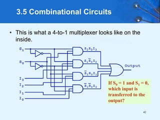
  • 30. 40 3.5 Combinational Circuits • A multiplexer does just the opposite of a decoder. • It selects a single output from several inputs. • The particular input chosen for output is determined by the value of the multiplexer’s control lines. • To be able to select among n inputs, log2n control lines are needed. This is a block diagram for a multiplexer.
  • 31. 41 3.5 Combinational Circuits • This is what a 4-to-1 multiplexer looks like on the inside. If S0 = 1 and S1 = 0, which input is transferred to the output?
  • 32. 42 3.5 Combinational Circuits • This shifter moves the bits of a nibble one position to the left or right. If S = 0, in which direction do the input bits shift?
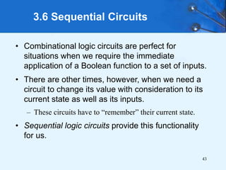
  • 33. 43 3.6 Sequential Circuits • Combinational logic circuits are perfect for situations when we require the immediate application of a Boolean function to a set of inputs. • There are other times, however, when we need a circuit to change its value with consideration to its current state as well as its inputs. – These circuits have to “remember” their current state. • Sequential logic circuits provide this functionality for us.
  • 34. 44 3.6 Sequential Circuits • As the name implies, sequential logic circuits require a means by which events can be sequenced. • State changes are controlled by clocks. – A “clock” is a special circuit that sends electrical pulses through a circuit. • Clocks produce electrical waveforms such as the one shown below.
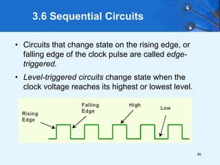
  • 35. 45 3.6 Sequential Circuits • State changes occur in sequential circuits only when the clock ticks. • Circuits can change state on the rising edge, falling edge, or when the clock pulse reaches its highest voltage.
  • 36. 46 3.6 Sequential Circuits • Circuits that change state on the rising edge, or falling edge of the clock pulse are called edge- triggered. • Level-triggered circuits change state when the clock voltage reaches its highest or lowest level.
  • 37. 47 3.6 Sequential Circuits • To retain their state values, sequential circuits rely on feedback. • Feedback in digital circuits occurs when an output is looped back to the input. • A simple example of this concept is shown below. – If Q is 0 it will always be 0, if it is 1, it will always be 1. Why?
  • 38. 48 3.6 Sequential Circuits • You can see how feedback works by examining the most basic sequential logic components, the SR flip-flop. – The “SR” stands for set/reset. • The internals of an SR flip-flop are shown below, along with its block diagram.
  • 39. 49 3.6 Sequential Circuits • The behavior of an SR flip-flop is described by a characteristic table. • Q(t) means the value of the output at time t. Q(t+1) is the value of Q after the next clock pulse.
  • 40. 50 3.6 Sequential Circuits • The SR flip-flop actually has three inputs: S, R, and its current output, Q. • Thus, we can construct a truth table for this circuit, as shown at the right. • Notice the two undefined values. When both S and R are 1, the SR flip- flop is unstable.
  • 41. 51 3.6 Sequential Circuits • If we can be sure that the inputs to an SR flip-flop will never both be 1, we will never have an unstable circuit. This may not always be the case. • The SR flip-flop can be modified to provide a stable state when both inputs are 1. • This modified flip-flop is called a JK flip-flop, shown at the right. - The “JK” is in honor of Jack Kilby.
  • 42. 52 3.6 Sequential Circuits • At the right, we see how an SR flip-flop can be modified to create a JK flip-flop. • The characteristic table indicates that the flip-flop is stable for all inputs.
  • 43. 53 3.6 Sequential Circuits • Another modification of the SR flip-flop is the D flip-flop, shown below with its characteristic table. • You will notice that the output of the flip-flop remains the same during subsequent clock pulses. The output changes only when the value of D changes.
  • 44. 54 3.6 Sequential Circuits • The D flip-flop is the fundamental circuit of computer memory. – D flip-flops are usually illustrated using the block diagram shown below. • The characteristic table for the D flip-flop is shown at the right.
  • 45. 55 3.6 Sequential Circuits • The behavior of sequential circuits can be expressed using characteristic tables or finite state machines (FSMs). – FSMs consist of a set of nodes that hold the states of the machine and a set of arcs that connect the states. • Moore and Mealy machines are two types of FSMs that are equivalent. – They differ only in how they express the outputs of the machine. • Moore machines place outputs on each node, while Mealy machines present their outputs on the transitions.
  • 46. 56 3.6 Sequential Circuits • The behavior of a JK flop-flop is depicted below by a Moore machine (left) and a Mealy machine (right).
  • 47. 57 3.6 Sequential Circuits • Although the behavior of Moore and Mealy machines is identical, their implementations differ. This is our Moore machine.
  • 48. 58 3.6 Sequential Circuits • Although the behavior of Moore and Mealy machines is identical, their implementations differ. This is our Mealy machine.
  • 49. 59 3.6 Sequential Circuits • It is difficult to express the complexities of actual implementations using only Moore and Mealy machines. – For one thing, they do not address the intricacies of timing very well. – Secondly, it is often the case that an interaction of numerous signals is required to advance a machine from one state to the next. • For these reasons, Christopher Clare invented the algorithmic state machine (ASM). The next slide illustrates the components of an ASM.
  • 51. 61 3.6 Sequential Circuits • This is an ASM for a microwave oven.
  • 52. 62 3.6 Sequential Circuits • Sequential circuits are used anytime that we have a “stateful” application. – A stateful application is one where the next state of the machine depends on the current state of the machine and the input. • A stateful application requires both combinational and sequential logic. • The following slides provide several examples of circuits that fall into this category. Can you think of others?
  • 53. 63 3.6 Sequential Circuits • This illustration shows a 4-bit register consisting of D flip-flops. You will usually see its block diagram (below) instead. A larger memory configuration is shown on the next slide.
  • 55. 65 3.6 Sequential Circuits • A binary counter is another example of a sequential circuit. • The low-order bit is complemented at each clock pulse. • Whenever it changes from 0 to 1, the next bit is complemented, and so on through the other flip-flops.
  • 56. 66 3.6 Sequential Circuits • Convolutional coding and decoding requires sequential circuits. • One important convolutional code is the (2,1) convolutional code that underlies the PRML code that is briefly described at the end of Chapter 2. • A (2, 1) convolutional code is so named because two symbols are output for every one symbol input. • A convolutional encoder for PRML with its characteristic table is shown on the next slide.
  • 58. 68 3.6 Sequential Circuits This is the Mealy machine for our encoder.
  • 59. 69 3.6 Sequential Circuits F(1101 0010) = 11 01 01 00 10 11 11 10. • The fact that there is a limited set of possible state transitions in the encoding process is crucial to the error correcting capabilities of PRML. • You can see by our Mealy machine for encoding that:
  • 60. 70 3.6 Sequential Circuits F(11 01 01 00 10 11 11 10) = 1101 0010 • The decoding of our code is provided by inverting the inputs and outputs of the Mealy machine for the encoding process. • You can see by our Mealy machine for decoding that:
  • 61. 71 3.6 Sequential Circuits F(00 10 11 11) = 1001 • Yet another way of looking at the decoding process is through a lattice diagram. • Here we have plotted the state transitions based on the input (top) and showing the output at the bottom for the string 00 10 11 11.
  • 62. 72 3.6 Sequential Circuits F(00 10 11 11) = 1001 • Suppose we receive the erroneous string: 10 10 11 11. • Here we have plotted the accumulated errors based on the allowable transitions. • The path of least error outputs 1001, thus 1001 is the string of maximum likelihood.
  • 63. 73 3.7 Designing Circuits • We have seen digital circuits from two points of view: digital analysis and digital synthesis. – Digital analysis explores the relationship between a circuits inputs and its outputs. – Digital synthesis creates logic diagrams using the values specified in a truth table. • Digital systems designers must also be mindful of the physical behaviors of circuits to include minute propagation delays that occur between the time when a circuit’s inputs are energized and when the output is accurate and stable.
  • 64. 74 3.7 Designing Circuits • Digital designers rely on specialized software to create efficient circuits. – Thus, software is an enabler for the construction of better hardware. • Of course, software is in reality a collection of algorithms that could just as well be implemented in hardware. – Recall the Principle of Equivalence of Hardware and Software.
  • 65. 75 3.7 Designing Circuits • When we need to implement a simple, specialized algorithm and its execution speed must be as fast as possible, a hardware solution is often preferred. • This is the idea behind embedded systems, which are small special-purpose computers that we find in many everyday things. • Embedded systems require special programming that demands an understanding of the operation of digital circuits, the basics of which you have learned in this chapter.
  • 66. 76 • Computers are implementations of Boolean logic. • Boolean functions are completely described by truth tables. • Logic gates are small circuits that implement Boolean operators. • The basic gates are AND, OR, and NOT. – The XOR gate is very useful in parity checkers and adders. • The “universal gates” are NOR, and NAND. Chapter 3 Conclusion
  • 67. 77 • Computer circuits consist of combinational logic circuits and sequential logic circuits. • Combinational circuits produce outputs (almost) immediately when their inputs change. • Sequential circuits require clocks to control their changes of state. • The basic sequential circuit unit is the flip-flop: The behaviors of the SR, JK, and D flip-flops are the most important to know. Chapter 3 Conclusion
  • 68. 78 • The behavior of sequential circuits can be expressed using characteristic tables or through various finite state machines. • Moore and Mealy machines are two finite state machines that model high-level circuit behavior. • Algorithmic state machines are better than Moore and Mealy machines at expressing timing and complex signal interactions. • Examples of sequential circuits include memory, counters, and Viterbi encoders and decoders. Chapter 3 Conclusion