![International Journal of Power Electronics and Drive Systems (IJPEDS)
Vol. 12, No. 3, September 2021, pp. 1751~1763
ISSN: 2088-8694, DOI: 10.11591/ijpeds.v12.i3.pp1751-1763 1751
Journal homepage: http://ijpeds.iaescore.com
A modified bridge-type nonsuperconducting fault current
limiter for distribution network application
Willy Stephen Tounsi Fokui1
, Michael Saulo2
, Livingstone Ngoo3
1
Department of Electrical Engineering, Pan African University Institute for Basic Sciences, Technology and Innovation,
Nairobi, Kenya
2
Department of Electrical and Electronics Engineering, Technical University of Mombasa, Kenya
3
Department of Electrical/Communication Engineering, Multimedia University of Kenya
Article Info ABSTRACT
Article history:
Received Mar 11, 2021
Revised Apr 29, 2021
Accepted Jul 12, 2021
The electrical distribution network is undergoing tremendous modifications
with the introduction of distributed generation technologies which have led
to an increase in fault current levels in the distribution network. Fault current
limiters have been developed as a promising technology to limit fault current
levels in power systems. Though, quite a number of fault current limiters
have been developed; the most common are the superconducting fault current
limiters, solid-state fault current limiters, and saturated core fault current
limiters. These fault current limiters present potential fault current limiting
solutions in power systems. Nevertheless, they encounter various challenges
hindering their deployment and commercialization. This research aimed at
designing a bridge-type nonsuperconducting fault current limiter with a novel
topology for distribution network applications. The proposed bridge-type
nonsuperconducting fault current limiter was designed and simulated using
PSCAD/EMTDC. Simulation results showed the effectiveness of the
proposed design in fault current limiting, voltage sag compensation during
fault conditions, and its ability not to affect the load voltage and current
during normal conditions as well as in suppressing the source powers during
fault conditions. Simulation results also showed very minimal power loss by
the fault current limiter during normal conditions.
Keywords:
Distribution network
Fault current levels
Fault current limiter
Nonsuperconducting
Power losses
This is an open access article under the CC BY-SA license.
Corresponding Author:
Willy Stephen Tounsi Fokui
Department of Electrical Engineering
Pan African University Institute for Basic Sciences, Technology and Innovation
P.O. Box 62000-00200, JKUAT Main Campus, Nairobi, Kenya
Email: willysytis@gmail.com
1. INTRODUCTION
In recent years, the electrical distribution network has grown in complexity with the introduction of
distributed generation (DG). These additional technologies have led to issues of increased power losses,
voltage sags/swells, and increased fault currents [1]. Research shows that high penetration of photovoltaic
(PV) systems can lead to an increase in fault current magnitude in the order of 7% [2]. These fault currents
are higher in locations closer to PV generations [3]. An increase in PV penetration leads to an increase in
fault currents which also leads to an increase in protective relays fault currents, and these relays fault currents
depend on the locations of the PV systems [4]. A sensitivity analysis on the impact of rooftop PV systems on
the distribution network showed that the presence of PV systems on a low voltage feeder increased short
circuit fault levels by 10% [5]. A single PV system will have very minimal contribution to fault current but
when considering the collective contribution from all PV systems installed across the network, the fault](https://image.slidesharecdn.com/21395-41408-2-pb-220128070038/85/A-modified-bridge-type-nonsuperconducting-fault-current-limiter-for-distribution-network-application-1-320.jpg)
![ ISSN: 2088-8694
Int J Pow Elec & Dri Syst, Vol. 12, No. 3, September 2021 : 1751 – 1763
1752
current contribution gets significantly higher with high PV penetration which could cause considerable
problems in the fault clearing operation of protective devices [6]. The integration of DGs has led to today’s
power systems having a short circuit current greater than what the operating equipment can handle [7], [[8].
This could greatly affect the reliability of existing protective mechanisms and that of the network, but these
reliabilities could be improved by using fault current limiting techniques such as fault current limiters [9].
Fault current limiters (FCLs) have been widely introduced in power systems as the most promising
technology to effectively and efficiently suppress fault currents to satisfactory levels [10]. The main goal of
FCLs is to lower the fault current to a level that the circuit breaker can conveniently and safely clear [11].
The utilization of FCLs in power system has not only been to suppress fault currents but has also been to
enable voltage ride-through capabilities of wind farm doubly-fed induction generators [12], [13], enhance
transient stability [14], eliminate voltage sags [15], improve power quality, limit inrush current in
transformers [14] and increase the power transfer capability of the power system [16]. Various types of FCLs
have been developed [17]; the most common being the superconducting fault current limiters (SFCLs), solid-
state fault current limiters (SSFCL) and saturated core fault current limiters (SCFCL) [18]. SFCLs are the
leading fault current limiting technology in the world and this is because of their high efficiency in
suppressing fault currents, fast response, automatic recovery after fault clearance, and their superconducting
ability that permits them to be invisible in the network during normal operation [19]. Notwithstanding, they
are still not yet widely deployed because of the technology and the expensive nature of the superconductors
[20]. This has led to the search for nonsuperconducting coils to be used in place of the superconducting coils
to achieve simpler and cost-effective fault current limiters [21]; this type being the nonsuperconducting fault
current limiters (NSFCLs). NSFCLs offer substantial alternatives to SFCLs due to their simplicity,
affordability, and minimal power losses during normal operation [22], [23]. FCLs of any type are designed to
be as close to ideal as possible; with an ideal FCL having the following qualities [24], a) an impedance of
zero during normal operation, b) fast and automatic impedance appearance at the occurrence of a fault,
c) sufficiently large impedance during fault conditions, d) rapid recovery after the fault has been cleared,
e) should reliably limit the defined fault current, f) no power losses, and g) low cost.
However, achieving all these specifications on a single FCL is almost impossible [24]. A lot of
research has been done on nonsuperconducting fault current limiters. For example, in [25], the authors
compared the current limiting capabilities of a DC reactor-type NSFCL with those of SFCL and noticed that
both fault current limiters led to the distortion of the line current and the load voltage, and consequently,
affecting the power quality of the network. Testing results of the NSFCL showed a line current during fault
being higher than that during normal conditions though far lower than the fault current when the NSFCL was
not used. Hence, despite using that NSFCL, the source still produces a considerably high current (above the
rated), unhealthy to the system during fault conditions until the fault is cleared. To cater for the line current
and load voltage distortions, the authors proposed the use of a DC source in series with the DC reactor for the
case of the NSFCL. In [26], a bridge-type fault current limiter that employs two isolation transformers was
proposed but this made the design not cost-effective. Other researchers have proposed substantial topologies
for fault current limiting, each presenting some drawbacks which include load current and voltage distortions,
power losses, and cost ineffectiveness [21]-[27]. In this research work, the problems enumerated are
addressed using a bridge-type NSFCL with a novel topology.
This paper proposes a modified bridge-type NSFCL for distribution network applications. The
NSFCL is made up of a bridge rectifier, two DC reactors, a semiconductor switch, and a simple command
circuit. The rest of this paper is structured as follows. The next section presents the simulation of the test
network used to validate the efficiency of the proposed NSFCL. In Section 2.3, the proposed NSFCL is
depicted and analytical analysis is carried out with the FCL inserted into the test network. In Section 3, the
simulation results are presented and discussed, and this is followed by a conclusion.
2. RESEARCH METHOD
2.1. Simulation of the test network
In this work, a single-phase extraction of the balanced IEEE 4 node test feeder with the transformer
removed is utilized as a test circuit or network. To obtain the test circuit, the load is referred to the primary
side of the transformer and the transformer removed. A single phase of the resulting network is then extracted
and used as a test circuit. The test network was built and simulated in PSCAD/EMTDC. The circuit is shown
in Figure 1 and the network parameters are shown in Table 1. It is noted that the simulation results obtained
agree very closely with those published by IEEE as seen in Table 2 [28].](https://image.slidesharecdn.com/21395-41408-2-pb-220128070038/85/A-modified-bridge-type-nonsuperconducting-fault-current-limiter-for-distribution-network-application-2-320.jpg)
![Int J Pow Elec & Dri Syst ISSN: 2088-8694
A modified bridge-type nonsuperconducting fault current limiter … (Willy Stephen Tounsi Fokui)
1753
Figure 1. Test network
Table 1. Test network parameters
Component Parameters
Source Source Voltage, Vs = 7.2kV,
Frequency, fs = 60Hz
Transmission line impedance Zline = 0.3061 + jω0.0001 ohm
Load impedance Zload = 14.975 + jω0.0397 ohm
Table 2. Comparison of test network simulation
results with published IEEE 4 node results
Parameter Bus IEEE Test
Network
Line to ground Voltage
(kV)
01 7.199 7.199
02 7.164 7.117
Phase Current (A) 01-
02
336.8 336.133
2.2. Faults and fault current calculation
A fault is an abnormal condition in the electrical network that comes as a result of the failure of
operating equipment. Two categories of faults can occur [29], a) The open-circuit fault that results in the
seizure of current flow in the circuit, and b) the short-circuit fault that is as a result of insulation failure due to
overloading and overstressing of feeders or degradation of feeder’s insulation which leads to high current
flow in the circuit.
Various methods are used for short-circuit fault current calculations, amongst them is the sequence
method. The sequence method of fault calculation involves building the impedance matrix of the circuit and
calculating the fault current. For an electrical circuit with a sending end voltage 𝑉
𝑠, a line impedance 𝑍𝑘 and a
load node j, the voltage 𝑉
𝑗 at node j before the occurrence of a ground fault at that node is given by;
𝑉
𝑗 = 𝑉
𝑠 − 𝐼𝑗𝑍𝑘 (1)
After the fault occurrence, the voltage 𝑉
𝑗 is zero giving a change in voltage of −𝑉
𝑗. As a result, the current
flow, 𝐼𝑓𝑗 from node j into the circuit is;
𝐼𝑓𝑗 = −
𝑉𝑗
𝑍𝑇
(2)
Where 𝐼𝑓𝑗 is the current from node j due to the fault and 𝑍𝑇 the total impedance due to the fault given by;
𝑍𝑇 = 𝑍𝑘 + 𝑍𝑓 (3)
Where 𝑍𝑘 is the line impedance and 𝑍𝑓 is the fault impedance.
Since before the fault, no current was flowing into the circuit from node j, the fault current, 𝐼𝑓 from the circuit
into node j is then calculated as;
𝐼𝑓 = −𝐼𝑓𝑗 =
𝑉𝑗
𝑍𝑇
(4)
The various types of short-circuit faults which are three-phase fault, single line-to-ground fault, double line-
to-ground fault, and line-to-line fault differ in their calculations by their expressions for 𝑍𝑇.
2.3. Proposed modified bridge-type nonsuperconducting fault current limiter
The topology of the proposed bridge-type NSFCL is shown in Figure 2 (a). The NSFCL is made up
of 3 main parts; a bridge rectifier, DC reactors, and a semiconductor switch. An insulated gate bipolar
transistor (IGBT) is used as the semiconductor switch. Two DC reactors; one of smaller value placed in
series with the IGBT and one of larger value placed in parallel with the IGBT. The IGBT is controlled by a
command circuit that turns it ON during normal conditions and OFF during fault conditions. The series
reactor is aimed at limiting the abrupt change in the current flow through the IGBT during a fault condition.
The DC reactors are modelled each with a reactance and a parasitic resistance.
2.3.1. Operation principle of the proposed NSFCL](https://image.slidesharecdn.com/21395-41408-2-pb-220128070038/85/A-modified-bridge-type-nonsuperconducting-fault-current-limiter-for-distribution-network-application-3-320.jpg)

![Int J Pow Elec & Dri Syst ISSN: 2088-8694
A modified bridge-type nonsuperconducting fault current limiter … (Willy Stephen Tounsi Fokui)
1755
i(t) = e−(
R
L
)(t−t0)
[i0 −
U
Z
sin(ωt0 − θ) +
2Ud
Z
] +
U
Z
sin(ωt0 − θ) −
2Ud
R
(12)
i(t) = iL(t) = id(t)
Figure 3. Line current and reactor current waveforms during normal operation
During the negative sequence of the line current, the series DC reactor is in the discharging mode
which begins at t2 as shown in Figure 3. In this mode, all the diodes are turned ON and the series DC reactor
is short-circuited. Hence do not interfere in the normal operation of the network, implying.
2Ud + Ls
di(t)
dt
+ rsid(t) = 0 (13)
id(t) = e
−(
rd
Ld
)(t−t2)
[i2 +
2Ud
rd
] −
2Ud
rd
(14)
the supplied line current in this mode can be obtained from;
Usin(ωt) = L
di(t)
dt
+ Ri(t) (15)
where:
L = Lline + Lload (16)
R = Rline + Rload (17)
therefore, from (17), line the current is obtained to be,
iL(t) = e−(
R
L
)(t−t2)
[i2 −
U
Z
sin(ωt2 − θ)] +
U
Z
sin(ωt2 − θ) (18)
where: Z = √R2 + (Lω)2, θ = tan−1 Lω
R
and i2 = i2(t)
The discharging of the series DC reactor is a result of its parasitic resistance. At t = t3, the series DC
reactor current again equalizes the line current. In the discharging mode; from t2 to t3, the DC reactor has no
effect on the network because it is not being charged. Similarly, the effect the series DC reactor has on the
network in the charging mode is very negligible because the current it carries is almost equal to that of the
line current. The charging and discharging currents of the series DC reactor are shown in equations (12) and
(18). From these equations, it is seen that both charging and discharging currents consist of ripple and DC
components. It is important to minimize the ripple component as much as possible because it is responsible
for the voltage drop across the series DC reactor’s inductance, Ls during normal operation [30]. The series
DC reactor current is given by
iDC = imax −
ird,p−p
2
(19)](https://image.slidesharecdn.com/21395-41408-2-pb-220128070038/85/A-modified-bridge-type-nonsuperconducting-fault-current-limiter-for-distribution-network-application-5-320.jpg)
![ ISSN: 2088-8694
Int J Pow Elec & Dri Syst, Vol. 12, No. 3, September 2021 : 1751 – 1763
1756
where imax is the reactor’s maximum current and ird,p−p is the peak to peak value of the reactor AC current.
From Figure 3,
ird,p−p = imax − i2 (20)
integrating the discharging equation (18), we obtain
ird,p−p ≅
T
Ls
(
rsimax
2
+ Ud) (21)
where: T = (t3 − t0) = 10ms for 50Hz networks [30].
From (19) and (20).
iDC ≅ imax (1 −
rsT
4Ls
) −
UdT
2Ls
(22)
for rs = 0
iDC ≅ imax −
UdT
2Ls
(23)
ird,p−p ≅
T
Ls
Ud (24)
from (23) and (24), it is seen that increasing Ls increases IDC and reduces the ripple component.
b. During fault conditions
During fault conditions, the IGBT is turned OFF and the parallel path is automatically and instantly
inserted into the network. In the charging mode in fault conditions, the source voltage is given by
Usin(ωt) = 2Ud + L
di(t)
dt
+ Ri(t) (25)
where:
L = Ls + Lline + Lp + Lload (26)
R = rs + Rline + Rp + Rload (27)
Z = √R2 + (Lω)2 (28)
θ = tan−1
(
Lω
R
) (29)
making i(t) the subject of (25), we obtain
i(t) = e−(
R
L
)(t−t7)
[i7 −
U
Z
sin(ωt7 − θ) +
2Ud
Z
] +
U
Z
sin(ωt7 − θ) −
2Ud
R
(30)
i(t) = iL(t) = id(t) and i7 = i7(t)
Where t7 is the time instant during fault when charging mode begins and i7 the current at that time.
During the discharge mode, just like in the normal condition, all the diodes enter into conduction and isolate
the reactors from the circuit.
Applying Kirchhoff’s voltage law;
2Ud + Ls
di(t)
dt
+ rsid(t) + Lp
di(t)
dt
+ rpid(t) = 0 (31)
id(t) = e
−(
Rd
Ld
)(t−t9)
[i8 +
2Ud
Rd
] −
2Ud
Rd
(32)](https://image.slidesharecdn.com/21395-41408-2-pb-220128070038/85/A-modified-bridge-type-nonsuperconducting-fault-current-limiter-for-distribution-network-application-6-320.jpg)
![Int J Pow Elec & Dri Syst ISSN: 2088-8694
A modified bridge-type nonsuperconducting fault current limiter … (Willy Stephen Tounsi Fokui)
1757
where
Rd = rs + Rp (33)
Ld = Ls + Lp (34)
t9 is the start of discharging during fault condition. The supplied current (inrush current) in this mode is
obtained from
Usin(ωt) = L
di(t)
dt
+ Ri(t) (35)
where:
L = Lline + Lload (36)
R = Rline + Rload (37)
therefore, the inrush current could be obtained from (35),
iL(t) = e−(
R
L
)(t−t9)
[i9 −
U
Z
sin(ωt9 − θ)] +
U
Z
sin(ωt9 − θ) (38)
where
Z = √R2 + (Lω)2, θ = tan−1 Lω
R
, i9 = i9(t)
c. Power losses through the FCL during normal operation
The active power loss through the DC reactor is given by;
PDCloss = rsiDC
2
= rs[[imax (1 −
rsT
4Ls
) −
UdT
2Ls
]
2
(39)
Assuming the ripple component of the reactor current being very small compared to the DC component and
negligible,
iDC = imax (40)
hence,
PDCloss = rdimax
2
(41)
load active power is given by
Pload = Uloadiload cos θ (42)
PDCloss = rsiDC
2
= rs[[imax (1 −
rsT
4Ls
) −
UdT
2Ls
]
2
(39)
Assuming the ripple component of the reactor current being very small compared to the DC component and
negligible,
iDC = imax (40)
hence,
PDCloss = rdimax
2
(41)
load active power is given by,
Pload = Uloadiload cos θ (42)](https://image.slidesharecdn.com/21395-41408-2-pb-220128070038/85/A-modified-bridge-type-nonsuperconducting-fault-current-limiter-for-distribution-network-application-7-320.jpg)

![Int J Pow Elec & Dri Syst ISSN: 2088-8694
A modified bridge-type nonsuperconducting fault current limiter … (Willy Stephen Tounsi Fokui)
1761
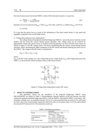
(a) (b)
Figure 10. Load Voltage at fault occurrence, (a) No NSFCL, and (b) With NSFCL
(a) (b)
Figure 11. Load current at fault current occurrence, (a) No NSFCL, and (b) With NSFCL
4. CONCLUSION
In this paper, the necessity of fault current limiters in power systems were examined and the
drawbacks of existing NSFCLs were outlined. The aim was to propose an efficient and effective bridge-type
nonsuperconducting fault current limiter with a novel topology for distribution network applications. The
target was to develop an NSFCL that is almost invisible to the network during normal network operation and
therefore leading to very minimal power losses, and on the other hand, adequately limiting the fault current to
desired values during fault conditions. The proposed modified bridge-type NSFCL was designed and
simulated using PSCAD/EMTDC and results showed outstanding performance of the novel NSFCL in, i)
fault current limiting, ii) sending end voltage sag compensation during the fault, iii) suppression to desired
values of supplied active and reactive powers during fault conditions, iv) not distorting load voltage and
current waveforms, and v) minimal power losses during normal condition.
The proposed modified bridge-type NSFCL proves to be better than existing NSFCLs in terms of
the reduced number of components used and the novel series and parallel DC reactors configuration used.
The proposed novel NSFCL is a cost-effective and all-in-one efficient solution for distribution network fault
current limiting, voltage ride-through capability enhancement, power quality improvement, and voltage sag
compensation. These problems are problems that are faced by the distribution network with the increasing
number of DGs being integrated into the network. With the proposed bridge-type NSFCL, there will be no
need for protective equipment upgrades or replacement. The future of this research work will be the practical
implementation of the proposed NSFCL to validate its practical effectiveness as simulation results have
demonstrated its effectiveness in distribution network applications.
ACKNOWLEDGEMENTS
Gratitudes to the African Union Commission for the scholarship offer to the corresponding author.
REFERENCES
[1] U. C. Chukwu, and S. M. Mahajan, “Real-time management of power systems with V2G facility for smart-grid
applications,” IEEE Transactions on Sustainable Energy, vol. 5, no. 2, pp. 558-566, April 2014, doi:
10.1109/TSTE.2013.2273314.](https://image.slidesharecdn.com/21395-41408-2-pb-220128070038/85/A-modified-bridge-type-nonsuperconducting-fault-current-limiter-for-distribution-network-application-11-320.jpg)
![ ISSN: 2088-8694
Int J Pow Elec & Dri Syst, Vol. 12, No. 3, September 2021 : 1751 – 1763
1762
[2] L. Mukwekwe, C. Venugopal, and I. E. Davidson, “A review of the impacts and mitigation strategies of high PV
penetration in low voltage networks,” IEEE PES Power Africa, pp. 274-279, 2017, doi:
10.1109/PowerAfrica.2017.7991236.
[3] P. K. Bhatt, and S. Y. Kumar, “Comprehensive assessment of fault current contribution in smart distribution grid
with solar photovoltaic,” Technol. Econ. Smart Grids Sustain. Energy, vol. 2, no. 7, pp. 1-14, 2017, doi:
10.1007/s40866-017-0023-8.
[4] B. S. Tekpeti, X. Kang, and X. Huang, “Fault analysis of solar photovoltaic penetrated distribution systems
including overcurrent relays in presence of fluctuations,” International Journal Electrical Power & Energy
Systems, vol. 100, pp. 517-530, 2018, doi: 10.1016/j.ijepes.2018.03.003.
[5] H. H. Yengejeh, F. Shahnia, and S. M. Islam, “Impact of distributed rooftop photovoltaic systems on short-circuit
faults in the supplying low voltage networks,” Electric Power Components and Systems, vol. 45, no. 20, pp. 2257-
2274, 2017, doi: 10.1080/15325008.2017.1408155.
[6] S. Bhattacharya, T. Saha, and M. J. Hossain, “Fault current contribution from photovoltaic systems in residential
power networks,” Australasian Universities Power Engineering Conference (AUPEC), 2013, pp. 1-6, doi:
10.1109/AUPEC.2013.6725450.
[7] L. Wang, P. Jiang, and D. Wang, “Summary of superconducting fault current limiter technology,” Frontiers in
Computer Education, vol. 133, pp. 819-825, 2012, doi: 10.1007/978-3-642-27552-4_108.
[8] S. M. Saad, N. E. Naily, J. Wafi, A. Elhaffar, and F. A. Mohamed, “Enhancement of over current coordination for a
distribution system connected to a microgrid using unidirectional fault current limiter,” in 2018 9th International
Renewable Energy Congress (IREC), 2018, pp. 1-6, doi: 10.1109/IREC.2018.8362558.
[9] S. Ghaemi, and M. Abapour, “Effect of fault current limiter (FCL) on reliability and protection coordination of
distribution system,” 24th Iranian Conference on Electrical Engineering (ICEE), 2016, pp. 726-731, doi:
10.1109/IranianCEE.2016.7585616.
[10] S. Patil, and A. Thorat, “Performance analysis of point of common coupling with bridge type fault current limiter
for distribution system,” 2017 International Conference on Circuit, Power and Computing Technologies
(ICCPCT), 2017, pp. 1-6, doi: 10.1109/ICCPCT.2017.8074267.
[11] J. Prigmore, and N. Uzelac, “Fault current limiting (FCL) devices and techniques,” in Ito H. (eds) Switching
Equipment. CIGRE Green Books. Springer, Cham, 2919, doi: 10.1007/978-3-319-72538-3_13.
[12] H. Shahbabaei, M. Radmehr, and M. Firouzi, “LVRT capability enhancement of DFIG-based wind farms by using
capacitive DC reactor-type fault current limiter,” International Journal of Electrical Power & Energy Systems, vol.
102, pp. 287-295, 2018, doi: 10.1016/j.ijepes.2018.04.031.
[13] S. S. Sahoo, P. M. Tripathi, and K. Chatterjee, “Low-cost non-superconducting DC-fault current limiter for the
enhancement of low-voltage ride through capability of doubly fed induction generator,” IETE Technical Review,
vol. 37, no. 4, pp. 418-437, 2020, doi: 10.1080/02564602.2019.1647803.
[14] M. T. Hagh, S. B. Naderi, and M. Jafari, “Application of non-superconducting fault current limiter to improve
transient stability,” in 2010 IEEE International Conference on Power and Energy, 2010, pp. 646-650, doi:
10.1109/PECON.2010.5697660.
[15] M. Jafari, S. B. Naderi, M. T. Hagh, M. Abapour, and S. H. Hosseini, “Voltage sag compensation of point of
common coupling (PCC) using fault current limiter,” IEEE Transactions on Power Delivery, vol. 26, no. 4, pp.
2638-2646, Oct. 2011, doi: 10.1109/TPWRD.2011.2161496.
[16] P. Sridhar, V. P. C. Rao, and B. P. Singh, “Optimum placement of fault current limiter in 11 kV distribution
system,” Materials Today: Proceedings, vol. 5, no. 1, pp. 758-64, 2018, doi: 10.1016/j.matpr.2017.11.144.
[17] R. Asghar, “Fault current limiters types, operations and its limitations,” International Journal of Scientific &
Engineering Research, vol. 9, no. 2, pp. 1020-1027, 2018.
[18] O. Arikan, and B. Kucukaydin, “A new approach to limit fault current with series – parallel resonance strategy,”
Electrical Engineering, vol. 102, pp. 1287-1296, 2020, doi: 10.1007/s00202-020-00952-5.
[19] D. Fedasyuk, P. Serdyuk, and Y. Semchyshyn, “Resistive superconducting fault current limiter simulation and
design,” in 2008 15th International Conference on Mixed Design of Integrated Circuits and Systems, 2008, pp.
349-353.
[20] M. T. Hagh, and M. Abapour, “Nonsuperconducting fault current limiter with controlling the magnitudes of fault
currents,” IEEE Transactions on Power Electronics, vol. 24, no. 3, pp. 613-619, March 2009, doi:
10.1109/TPEL.2008.2004496.
[21] M. Abdolkarimzadeh, M. Nazari-Heris, M. Abapour, and M. Sabahi, “A bridge-type fault current limiter for energy
management of AC/DC microgrids,” IEEE Transactions on Power Electronics, vol. 32, no. 12, pp. 9043-9050,
Dec. 2017, doi: 10.1109/TPEL.2017.2655106.
[22] A. Agheli, H. A. Abyaneh, R. M. Chabanloo, and H. H. Dezaki, “Reducing the impact of DG in distribution
networks protection using fault current limiters,” in 2010 4th International Power Engineering and Optimization
Conference (PEOCO), 2010, pp. 298-303, doi: 10.1109/PEOCO.2010.5559205.
[23] M. S. Alam, M. A. Y. Abido, and I. El-Amin, “Fault current limiters in power systems: A comprehensive review,”
Energies, vol. 11, no. 5, pp. 1-24, 2018, doi: 10.3390/en11051025.
[24] M. Yamaguchi, S. Fukui, T. Satoh, Y. Kaburaki, T. Horikawa, and T. Honjo, “Performance of DC reactor type fault
current limiter using high temperature superconducting coil,” IEEE Transactions on Applied Superconductivity,
vol. 9, no. 2, pp. 940-943, June 1999, doi: 10.1109/77.783452.
[25] M. T. Hagh, and M. Abapour, “Non-superconducting fault current limiters,” European Transactions on Electrical
Power, vol. 19, no. 5, pp. 669-682, 2008, doi: 10.1002/etep.247.](https://image.slidesharecdn.com/21395-41408-2-pb-220128070038/85/A-modified-bridge-type-nonsuperconducting-fault-current-limiter-for-distribution-network-application-12-320.jpg)
![Int J Pow Elec & Dri Syst ISSN: 2088-8694
A modified bridge-type nonsuperconducting fault current limiter … (Willy Stephen Tounsi Fokui)
1763
[26] C. Tu, Q. Guo, F. Jiang, Z. Shuai, and X. He, “Electrical power and energy systems analysis and control of bridge-
type fault current limiter integrated with the dynamic voltage restorer,” International Journal of Electrical Power &
Energy Systems, vol. 95, pp. 315-326, 2018, doi: 10.1016/j.ijepes.2017.08.031.
[27] T. Ghanbari, E. Farjah, and N. Tashakor, “Thyristor based bridge-type fault current limiter for fault current limiting
capability enhancement,” IET Digital Library, vol. 10, pp. 2202-2215, 2016, doi: 10.1049/iet-gtd.2015.1364.
[28] “IEEE 4 node test feeder,” Distribution System Analysis Subcommittee, 2006.
[29] N. D. Tleis, Power systems modelling and fault analysis, Newnes, 2008, doi: 10.1016/C2017-0-02262-0.
[30] M. M. Hosseini, V. Noroozi, and A. Moslemi, “Power loss and ripple current analysis of a DC reactor type fault
current limiter,” Australian Journal of Basic and Applied Sciences, vol. 5, no. 5, pp. 448-454, 2011.
BIOGRAPHIES OF AUTHORS
Willy Stephen Tounsi Fokui is a Ph.D. candidate in Electrical Engineering at the Pan African
University Institute for Basic Sciences, Technology and Innovation, Nairobi, Kenya. He
obtained his Master of Engineering in Power Systems and Bachelor of Engineering in
Electrical and Electronic Engineering in the years 2017 and 2014 respectively. Both degrees
were awarded by the University of Buea, Cameroon. His research interests include
photovoltaic systems, energy management systems, distributed generation, and electric vehicle
integration into the electrical distribution network.
Dr. Michael J. Saulo possesses a doctorate and a Master’s degree in Electrical Power Systems
Engineering from the University of Cape Town South Africa and a Bachelor of Technology
from the Cape Peninsula University of Technology in South Africa. He is a career researcher
and Senior lecturer in the field of Electrical Power and Renewable Energy Systems at the
Technical University of Mombasa (TUM). Currently, he is the Registrar in charge of
Partnership, Research, and Innovation in the same university. He is a fellow member of the
Institute of Engineering Technologist of Kenya (FIET) and a Registered Graduate Engineer
with the Engineers Registration Board (ERB). His passion for research has resulted in over 70
publications in peer-reviewed journals and two books.
Prof. Livingstone Ngoo is a professional electrical engineer, University administrator,
researcher, and associate professor at the Faculty of Engineering & Technology (FoET) of the
Multimedia University of Kenya (MMU). He holds a Ph.D. in Electrical Power systems
automation. He has designed, supervised, and commissioned electrical works and generators in
public and private institutions. Prof. Ngoo research interests include the application of
renewable energy resources in agricultural production and power systems. He has also
published several papers in power systems while supervising over 15 graduate students.](https://image.slidesharecdn.com/21395-41408-2-pb-220128070038/85/A-modified-bridge-type-nonsuperconducting-fault-current-limiter-for-distribution-network-application-13-320.jpg)
A modified bridge-type nonsuperconducting fault current limiter for distribution network application
- 1. International Journal of Power Electronics and Drive Systems (IJPEDS) Vol. 12, No. 3, September 2021, pp. 1751~1763 ISSN: 2088-8694, DOI: 10.11591/ijpeds.v12.i3.pp1751-1763 1751 Journal homepage: http://ijpeds.iaescore.com A modified bridge-type nonsuperconducting fault current limiter for distribution network application Willy Stephen Tounsi Fokui1 , Michael Saulo2 , Livingstone Ngoo3 1 Department of Electrical Engineering, Pan African University Institute for Basic Sciences, Technology and Innovation, Nairobi, Kenya 2 Department of Electrical and Electronics Engineering, Technical University of Mombasa, Kenya 3 Department of Electrical/Communication Engineering, Multimedia University of Kenya Article Info ABSTRACT Article history: Received Mar 11, 2021 Revised Apr 29, 2021 Accepted Jul 12, 2021 The electrical distribution network is undergoing tremendous modifications with the introduction of distributed generation technologies which have led to an increase in fault current levels in the distribution network. Fault current limiters have been developed as a promising technology to limit fault current levels in power systems. Though, quite a number of fault current limiters have been developed; the most common are the superconducting fault current limiters, solid-state fault current limiters, and saturated core fault current limiters. These fault current limiters present potential fault current limiting solutions in power systems. Nevertheless, they encounter various challenges hindering their deployment and commercialization. This research aimed at designing a bridge-type nonsuperconducting fault current limiter with a novel topology for distribution network applications. The proposed bridge-type nonsuperconducting fault current limiter was designed and simulated using PSCAD/EMTDC. Simulation results showed the effectiveness of the proposed design in fault current limiting, voltage sag compensation during fault conditions, and its ability not to affect the load voltage and current during normal conditions as well as in suppressing the source powers during fault conditions. Simulation results also showed very minimal power loss by the fault current limiter during normal conditions. Keywords: Distribution network Fault current levels Fault current limiter Nonsuperconducting Power losses This is an open access article under the CC BY-SA license. Corresponding Author: Willy Stephen Tounsi Fokui Department of Electrical Engineering Pan African University Institute for Basic Sciences, Technology and Innovation P.O. Box 62000-00200, JKUAT Main Campus, Nairobi, Kenya Email: [email protected] 1. INTRODUCTION In recent years, the electrical distribution network has grown in complexity with the introduction of distributed generation (DG). These additional technologies have led to issues of increased power losses, voltage sags/swells, and increased fault currents [1]. Research shows that high penetration of photovoltaic (PV) systems can lead to an increase in fault current magnitude in the order of 7% [2]. These fault currents are higher in locations closer to PV generations [3]. An increase in PV penetration leads to an increase in fault currents which also leads to an increase in protective relays fault currents, and these relays fault currents depend on the locations of the PV systems [4]. A sensitivity analysis on the impact of rooftop PV systems on the distribution network showed that the presence of PV systems on a low voltage feeder increased short circuit fault levels by 10% [5]. A single PV system will have very minimal contribution to fault current but when considering the collective contribution from all PV systems installed across the network, the fault
- 2. ISSN: 2088-8694 Int J Pow Elec & Dri Syst, Vol. 12, No. 3, September 2021 : 1751 – 1763 1752 current contribution gets significantly higher with high PV penetration which could cause considerable problems in the fault clearing operation of protective devices [6]. The integration of DGs has led to today’s power systems having a short circuit current greater than what the operating equipment can handle [7], [[8]. This could greatly affect the reliability of existing protective mechanisms and that of the network, but these reliabilities could be improved by using fault current limiting techniques such as fault current limiters [9]. Fault current limiters (FCLs) have been widely introduced in power systems as the most promising technology to effectively and efficiently suppress fault currents to satisfactory levels [10]. The main goal of FCLs is to lower the fault current to a level that the circuit breaker can conveniently and safely clear [11]. The utilization of FCLs in power system has not only been to suppress fault currents but has also been to enable voltage ride-through capabilities of wind farm doubly-fed induction generators [12], [13], enhance transient stability [14], eliminate voltage sags [15], improve power quality, limit inrush current in transformers [14] and increase the power transfer capability of the power system [16]. Various types of FCLs have been developed [17]; the most common being the superconducting fault current limiters (SFCLs), solid- state fault current limiters (SSFCL) and saturated core fault current limiters (SCFCL) [18]. SFCLs are the leading fault current limiting technology in the world and this is because of their high efficiency in suppressing fault currents, fast response, automatic recovery after fault clearance, and their superconducting ability that permits them to be invisible in the network during normal operation [19]. Notwithstanding, they are still not yet widely deployed because of the technology and the expensive nature of the superconductors [20]. This has led to the search for nonsuperconducting coils to be used in place of the superconducting coils to achieve simpler and cost-effective fault current limiters [21]; this type being the nonsuperconducting fault current limiters (NSFCLs). NSFCLs offer substantial alternatives to SFCLs due to their simplicity, affordability, and minimal power losses during normal operation [22], [23]. FCLs of any type are designed to be as close to ideal as possible; with an ideal FCL having the following qualities [24], a) an impedance of zero during normal operation, b) fast and automatic impedance appearance at the occurrence of a fault, c) sufficiently large impedance during fault conditions, d) rapid recovery after the fault has been cleared, e) should reliably limit the defined fault current, f) no power losses, and g) low cost. However, achieving all these specifications on a single FCL is almost impossible [24]. A lot of research has been done on nonsuperconducting fault current limiters. For example, in [25], the authors compared the current limiting capabilities of a DC reactor-type NSFCL with those of SFCL and noticed that both fault current limiters led to the distortion of the line current and the load voltage, and consequently, affecting the power quality of the network. Testing results of the NSFCL showed a line current during fault being higher than that during normal conditions though far lower than the fault current when the NSFCL was not used. Hence, despite using that NSFCL, the source still produces a considerably high current (above the rated), unhealthy to the system during fault conditions until the fault is cleared. To cater for the line current and load voltage distortions, the authors proposed the use of a DC source in series with the DC reactor for the case of the NSFCL. In [26], a bridge-type fault current limiter that employs two isolation transformers was proposed but this made the design not cost-effective. Other researchers have proposed substantial topologies for fault current limiting, each presenting some drawbacks which include load current and voltage distortions, power losses, and cost ineffectiveness [21]-[27]. In this research work, the problems enumerated are addressed using a bridge-type NSFCL with a novel topology. This paper proposes a modified bridge-type NSFCL for distribution network applications. The NSFCL is made up of a bridge rectifier, two DC reactors, a semiconductor switch, and a simple command circuit. The rest of this paper is structured as follows. The next section presents the simulation of the test network used to validate the efficiency of the proposed NSFCL. In Section 2.3, the proposed NSFCL is depicted and analytical analysis is carried out with the FCL inserted into the test network. In Section 3, the simulation results are presented and discussed, and this is followed by a conclusion. 2. RESEARCH METHOD 2.1. Simulation of the test network In this work, a single-phase extraction of the balanced IEEE 4 node test feeder with the transformer removed is utilized as a test circuit or network. To obtain the test circuit, the load is referred to the primary side of the transformer and the transformer removed. A single phase of the resulting network is then extracted and used as a test circuit. The test network was built and simulated in PSCAD/EMTDC. The circuit is shown in Figure 1 and the network parameters are shown in Table 1. It is noted that the simulation results obtained agree very closely with those published by IEEE as seen in Table 2 [28].
- 3. Int J Pow Elec & Dri Syst ISSN: 2088-8694 A modified bridge-type nonsuperconducting fault current limiter … (Willy Stephen Tounsi Fokui) 1753 Figure 1. Test network Table 1. Test network parameters Component Parameters Source Source Voltage, Vs = 7.2kV, Frequency, fs = 60Hz Transmission line impedance Zline = 0.3061 + jω0.0001 ohm Load impedance Zload = 14.975 + jω0.0397 ohm Table 2. Comparison of test network simulation results with published IEEE 4 node results Parameter Bus IEEE Test Network Line to ground Voltage (kV) 01 7.199 7.199 02 7.164 7.117 Phase Current (A) 01- 02 336.8 336.133 2.2. Faults and fault current calculation A fault is an abnormal condition in the electrical network that comes as a result of the failure of operating equipment. Two categories of faults can occur [29], a) The open-circuit fault that results in the seizure of current flow in the circuit, and b) the short-circuit fault that is as a result of insulation failure due to overloading and overstressing of feeders or degradation of feeder’s insulation which leads to high current flow in the circuit. Various methods are used for short-circuit fault current calculations, amongst them is the sequence method. The sequence method of fault calculation involves building the impedance matrix of the circuit and calculating the fault current. For an electrical circuit with a sending end voltage 𝑉 𝑠, a line impedance 𝑍𝑘 and a load node j, the voltage 𝑉 𝑗 at node j before the occurrence of a ground fault at that node is given by; 𝑉 𝑗 = 𝑉 𝑠 − 𝐼𝑗𝑍𝑘 (1) After the fault occurrence, the voltage 𝑉 𝑗 is zero giving a change in voltage of −𝑉 𝑗. As a result, the current flow, 𝐼𝑓𝑗 from node j into the circuit is; 𝐼𝑓𝑗 = − 𝑉𝑗 𝑍𝑇 (2) Where 𝐼𝑓𝑗 is the current from node j due to the fault and 𝑍𝑇 the total impedance due to the fault given by; 𝑍𝑇 = 𝑍𝑘 + 𝑍𝑓 (3) Where 𝑍𝑘 is the line impedance and 𝑍𝑓 is the fault impedance. Since before the fault, no current was flowing into the circuit from node j, the fault current, 𝐼𝑓 from the circuit into node j is then calculated as; 𝐼𝑓 = −𝐼𝑓𝑗 = 𝑉𝑗 𝑍𝑇 (4) The various types of short-circuit faults which are three-phase fault, single line-to-ground fault, double line- to-ground fault, and line-to-line fault differ in their calculations by their expressions for 𝑍𝑇. 2.3. Proposed modified bridge-type nonsuperconducting fault current limiter The topology of the proposed bridge-type NSFCL is shown in Figure 2 (a). The NSFCL is made up of 3 main parts; a bridge rectifier, DC reactors, and a semiconductor switch. An insulated gate bipolar transistor (IGBT) is used as the semiconductor switch. Two DC reactors; one of smaller value placed in series with the IGBT and one of larger value placed in parallel with the IGBT. The IGBT is controlled by a command circuit that turns it ON during normal conditions and OFF during fault conditions. The series reactor is aimed at limiting the abrupt change in the current flow through the IGBT during a fault condition. The DC reactors are modelled each with a reactance and a parasitic resistance. 2.3.1. Operation principle of the proposed NSFCL
- 4. ISSN: 2088-8694 Int J Pow Elec & Dri Syst, Vol. 12, No. 3, September 2021 : 1751 – 1763 1754 The proposed modified bridge-type NSFCL operates as follows; a. During normal conditions (no fault), the IGBT is turned ON and the parallel branch (Rp, Lp) short- circuited. The series reactor (Ls, rs) is fully charged to the maximum current supplied by the source and therefore acts like a short-circuit. This makes it invisible to the network during normal conditions. The IGBT is kept ON by a command circuit that monitors the series reactor current and compares it with a predefined threshold value so that inasmuch as the series reactor current is lesser than the threshold current, the IGBT remains ON. b. During a fault condition, the IGBT is turned OFF because the series DC reactor current, Id becomes greater than the threshold current. The parallel reactor (Lp, Rp) is automatically and quickly inserted into the circuit, thereby limiting the fault current. The IGBT will continuously switch ON/OFF during fault conditions until the fault is cleared; leading to a distorted supplied current waveform during a fault condition. To solve this, an appropriate switching time is chosen for effective fault current limiting capabilities and a relatively smooth limited current during fault conditions. 2.3.2. Analytical analysis The proposed NSFCL inserted into the test network is shown in Figure 2 (b) and analyzed as follows; (a) (b) Figure 2. Proposed Bridge-type NSFCL, (a) standalone, (b) inserted into the test network a. During normal conditions The waveforms of the line and series DC reactor currents during normal conditions are shown in Figure 3. During normal conditions, the reactor charges during the positive cycle of the line current and discharges during the negative cycle. During charging, current flows from the source through D1, Ls, rs, IGBT, and D3 to the load through the transmission line. The voltage equation, in this case, is given by; u(t) = Ud + Ls di(t) dt + rsi(t) + Ud + Rlinei(t) + Lline di(t) dt + Rloadi(t) + Lload di(t) dt (5) Usin(ωt) = 2Ud + (Ls + Lline + Lload) di(t) dt + (rs + Rline + Rload)i(t) (6) Usin(ωt) = 2Ud + L di(t) dt + Ri(t) (7) where: L = Ls + Lline + Lload (8) R = rs + Rline + Rload (9) The impedance, Z = √R2 + (Lω)2 (10) and tanθ = Lω R (11) making i(t) the subject of the (9), we obtain
- 5. Int J Pow Elec & Dri Syst ISSN: 2088-8694 A modified bridge-type nonsuperconducting fault current limiter … (Willy Stephen Tounsi Fokui) 1755 i(t) = e−( R L )(t−t0) [i0 − U Z sin(ωt0 − θ) + 2Ud Z ] + U Z sin(ωt0 − θ) − 2Ud R (12) i(t) = iL(t) = id(t) Figure 3. Line current and reactor current waveforms during normal operation During the negative sequence of the line current, the series DC reactor is in the discharging mode which begins at t2 as shown in Figure 3. In this mode, all the diodes are turned ON and the series DC reactor is short-circuited. Hence do not interfere in the normal operation of the network, implying. 2Ud + Ls di(t) dt + rsid(t) = 0 (13) id(t) = e −( rd Ld )(t−t2) [i2 + 2Ud rd ] − 2Ud rd (14) the supplied line current in this mode can be obtained from; Usin(ωt) = L di(t) dt + Ri(t) (15) where: L = Lline + Lload (16) R = Rline + Rload (17) therefore, from (17), line the current is obtained to be, iL(t) = e−( R L )(t−t2) [i2 − U Z sin(ωt2 − θ)] + U Z sin(ωt2 − θ) (18) where: Z = √R2 + (Lω)2, θ = tan−1 Lω R and i2 = i2(t) The discharging of the series DC reactor is a result of its parasitic resistance. At t = t3, the series DC reactor current again equalizes the line current. In the discharging mode; from t2 to t3, the DC reactor has no effect on the network because it is not being charged. Similarly, the effect the series DC reactor has on the network in the charging mode is very negligible because the current it carries is almost equal to that of the line current. The charging and discharging currents of the series DC reactor are shown in equations (12) and (18). From these equations, it is seen that both charging and discharging currents consist of ripple and DC components. It is important to minimize the ripple component as much as possible because it is responsible for the voltage drop across the series DC reactor’s inductance, Ls during normal operation [30]. The series DC reactor current is given by iDC = imax − ird,p−p 2 (19)
- 6. ISSN: 2088-8694 Int J Pow Elec & Dri Syst, Vol. 12, No. 3, September 2021 : 1751 – 1763 1756 where imax is the reactor’s maximum current and ird,p−p is the peak to peak value of the reactor AC current. From Figure 3, ird,p−p = imax − i2 (20) integrating the discharging equation (18), we obtain ird,p−p ≅ T Ls ( rsimax 2 + Ud) (21) where: T = (t3 − t0) = 10ms for 50Hz networks [30]. From (19) and (20). iDC ≅ imax (1 − rsT 4Ls ) − UdT 2Ls (22) for rs = 0 iDC ≅ imax − UdT 2Ls (23) ird,p−p ≅ T Ls Ud (24) from (23) and (24), it is seen that increasing Ls increases IDC and reduces the ripple component. b. During fault conditions During fault conditions, the IGBT is turned OFF and the parallel path is automatically and instantly inserted into the network. In the charging mode in fault conditions, the source voltage is given by Usin(ωt) = 2Ud + L di(t) dt + Ri(t) (25) where: L = Ls + Lline + Lp + Lload (26) R = rs + Rline + Rp + Rload (27) Z = √R2 + (Lω)2 (28) θ = tan−1 ( Lω R ) (29) making i(t) the subject of (25), we obtain i(t) = e−( R L )(t−t7) [i7 − U Z sin(ωt7 − θ) + 2Ud Z ] + U Z sin(ωt7 − θ) − 2Ud R (30) i(t) = iL(t) = id(t) and i7 = i7(t) Where t7 is the time instant during fault when charging mode begins and i7 the current at that time. During the discharge mode, just like in the normal condition, all the diodes enter into conduction and isolate the reactors from the circuit. Applying Kirchhoff’s voltage law; 2Ud + Ls di(t) dt + rsid(t) + Lp di(t) dt + rpid(t) = 0 (31) id(t) = e −( Rd Ld )(t−t9) [i8 + 2Ud Rd ] − 2Ud Rd (32)
- 7. Int J Pow Elec & Dri Syst ISSN: 2088-8694 A modified bridge-type nonsuperconducting fault current limiter … (Willy Stephen Tounsi Fokui) 1757 where Rd = rs + Rp (33) Ld = Ls + Lp (34) t9 is the start of discharging during fault condition. The supplied current (inrush current) in this mode is obtained from Usin(ωt) = L di(t) dt + Ri(t) (35) where: L = Lline + Lload (36) R = Rline + Rload (37) therefore, the inrush current could be obtained from (35), iL(t) = e−( R L )(t−t9) [i9 − U Z sin(ωt9 − θ)] + U Z sin(ωt9 − θ) (38) where Z = √R2 + (Lω)2, θ = tan−1 Lω R , i9 = i9(t) c. Power losses through the FCL during normal operation The active power loss through the DC reactor is given by; PDCloss = rsiDC 2 = rs[[imax (1 − rsT 4Ls ) − UdT 2Ls ] 2 (39) Assuming the ripple component of the reactor current being very small compared to the DC component and negligible, iDC = imax (40) hence, PDCloss = rdimax 2 (41) load active power is given by Pload = Uloadiload cos θ (42) PDCloss = rsiDC 2 = rs[[imax (1 − rsT 4Ls ) − UdT 2Ls ] 2 (39) Assuming the ripple component of the reactor current being very small compared to the DC component and negligible, iDC = imax (40) hence, PDCloss = rdimax 2 (41) load active power is given by, Pload = Uloadiload cos θ (42)
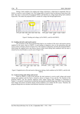
- 8. ISSN: 2088-8694 Int J Pow Elec & Dri Syst, Vol. 12, No. 3, September 2021 : 1751 – 1763 1758 the ratio of active power loss by the NSFCL to that of the load reactive power, n is given by, n = PDCloss Pload = rsimax 2 Uloadiloadcos (θ) (43) therefore, for our test network of Uload=7.2kV, iload=336.128A, cosθ=0.9, rd=0.003 and imax=475.357A, n = 0.31% It is seen that the power loss as a result of the introduction of the fault current limiter is very small and negligible compared to the overall feeder losses. d. Voltage drop and power loss compensation The voltage drop in the proposed modified bridge-type NSFCL is across the power electronic switch (IGBT) and the series DC reactor during normal operation. This voltage drop can be resolved by appropriately sizing a DC power source or rectifier circuit and placing it in series with the series reactor as shown in Figure 4. The DC voltage source will aid in smoothening the DC reactor current during normal operation. Hence eliminating the ripple component of the DC current and thereby reducing the power loss in the NSFCL. The voltage of the DC source is calculated as: Ubat = 2Ud + Usw + rsId (44) where: Ubat is the DC source voltage, Ud is the voltage drop across a single diode, Usw is the voltage drop across the IGBT, rs is the series DC reactor resistance and Id is the reactor current. Figure 4. Voltage drop compensation using a DC source 3. RESULTS AND DISCUSSION The parameters chosen for the simulation of the proposed bridge-type NSFCL using PSCAD/EMTDC are shown in Table 3. Electromagnetic transient analysis of the test network was done without the proposed modified bridge-type NSFCL, with the NSFCL, and with the NSFCL with battery. The simulation settings were; a) simulation runtime of 0.5s, b) a line-to-ground fault occurred at 0.3s and lasted for 0.05s, and c) the circuit breaker cleared the fault 0.03s after its occurrence (that is at 0.33s) and restored the network 0.07s later (at 0.4s). The simulation results are: Table 3. Simulation parameters Parameters Source Source Voltage, Vs = 7.2kV, Frequency, fs = 60Hz Transmission line impedance Zline = 0.3061 + jω0.0001 ohm Load impedance Zload = 14.975 + jω0.0397 ohm Fault Fault ON resistance, Rf = 0.01 ohm Fault Current Limiter L𝑠 = 0.01H, r𝑠 = 0.003 ohm, Lp = 0.2H, Rp = 20 ohm, Ud = 1V
- 9. Int J Pow Elec & Dri Syst ISSN: 2088-8694 A modified bridge-type nonsuperconducting fault current limiter … (Willy Stephen Tounsi Fokui) 1759 3.1. Line current The line current shoots to more than 30kA during fault conditions when no NSFCL is used as can be seen in Figure 5. With the insertion of the proposed bridged-type NSFCL, the fault current is limited to the desired value (below 0.6kA), thereby protecting the source and the load during fault and enabling the circuit breaker to safely clear the fault as shown in Figures 6 (a) and (b). This also removes any possible stress on the network during fault conditions. The introduction of a DC source in the NSFCL smoothens the DC reactor current during normal conditions (Figure 6 (b)) compared to without the DC source (Figure 6 (a)). Hence reduces power losses in the NSFCL as shown in Table 4. In addition, the designed bridge-type NSFCL does not affect the line current waveform during normal conditions as seen in Figures 7 (a)-(c). Figure 5. Line current during normal, fault, fault cleared and system restored conditions with no NSFCL (a) (b) Figure 6. Line current (Ia) and reactor current (Id) during normal, fault, fault cleared and system restored conditions with NSFCL, (a) NSFCL with no DC source, (b) NSFCL with DC source Table 4: Comparison of power losses and voltage drop with no FCL, with FCL and with FCL with battery No FCL With FCL with no battery With FCL with battery Sending End Receiving End Losses Sending End Receiving End Losses Sending End Receiving End Losses Active Power/kW 1.851 1.784 0.067 1.818 1.772 0.046 1.82 1.778 0.042 Reactive Power / kVar 1.564 1.563 0.001 1.559 1.552 0.007 1.562 1.557 0.005 Voltage / kV 7.199 7.117 0.082 7.199 7.097 0.102 7.199 7.107 0.092 (a) (b) (c) Figure 7. No Distortion in line current during normal conditions, (a) No NSFCL, (b) NSFCL with no DC source, and (c) NSFCL with DC source 3.2. Sending end voltage
- 10. ISSN: 2088-8694 Int J Pow Elec & Dri Syst, Vol. 12, No. 3, September 2021 : 1751 – 1763 1760 During a fault condition, the sending end voltage experiences a slight drop in magnitude when no NSFCL is used as is seen in Figure 8 (a). This voltage drop is a result of stress on the power source due to the fault. This stress is removed by the proposed NSFCL and therefore no voltage drops during fault condition Figure 8(b). This makes the proposed NSFCL suitable for voltage ride-through applications. (a) (b) Figure 8. Sending end voltage, (a) No NSFCL, and (b) with NSFCL 3.3. Sending end active and reactive power The occurrence of the line-to-ground fault leads to an overshoot of the active and reactive powers supplied by the source when no NSFCL is used leading to dangerous stress on the generating units and excess system overload as shown in Figure 9 (a). This situation is adequately solved by the proposed NSFCL which keeps the supplied active and reactive powers within limits during fault conditions until the fault is cleared by the circuit breaker as can be seen in Figure 9 (b). (a) (b) Figure 9. Supplied active (Pa) and reactive (Qa) power during a fault condition (a) No NSFCL, and (b) with NSFCL 3.4. Load (receiving end) voltage and current When no NSFCL is used in the network, the load continues to receive small voltage and current during fault condition until the fault is cleared as shown in Figures 10 (a), and (b). The insertion of the proposed NSFCL into the network suppresses these ripples during fault conditions as illustrated in Figures 11 (a) and (b). It should also be noted that the proposed modified bridge-type NSFCL does not distort load voltage and current waveforms during normal conditions even without the DC source. Therefore, the proposed design does not introduce total harmonic distortions in the network.
- 11. Int J Pow Elec & Dri Syst ISSN: 2088-8694 A modified bridge-type nonsuperconducting fault current limiter … (Willy Stephen Tounsi Fokui) 1761 (a) (b) Figure 10. Load Voltage at fault occurrence, (a) No NSFCL, and (b) With NSFCL (a) (b) Figure 11. Load current at fault current occurrence, (a) No NSFCL, and (b) With NSFCL 4. CONCLUSION In this paper, the necessity of fault current limiters in power systems were examined and the drawbacks of existing NSFCLs were outlined. The aim was to propose an efficient and effective bridge-type nonsuperconducting fault current limiter with a novel topology for distribution network applications. The target was to develop an NSFCL that is almost invisible to the network during normal network operation and therefore leading to very minimal power losses, and on the other hand, adequately limiting the fault current to desired values during fault conditions. The proposed modified bridge-type NSFCL was designed and simulated using PSCAD/EMTDC and results showed outstanding performance of the novel NSFCL in, i) fault current limiting, ii) sending end voltage sag compensation during the fault, iii) suppression to desired values of supplied active and reactive powers during fault conditions, iv) not distorting load voltage and current waveforms, and v) minimal power losses during normal condition. The proposed modified bridge-type NSFCL proves to be better than existing NSFCLs in terms of the reduced number of components used and the novel series and parallel DC reactors configuration used. The proposed novel NSFCL is a cost-effective and all-in-one efficient solution for distribution network fault current limiting, voltage ride-through capability enhancement, power quality improvement, and voltage sag compensation. These problems are problems that are faced by the distribution network with the increasing number of DGs being integrated into the network. With the proposed bridge-type NSFCL, there will be no need for protective equipment upgrades or replacement. The future of this research work will be the practical implementation of the proposed NSFCL to validate its practical effectiveness as simulation results have demonstrated its effectiveness in distribution network applications. ACKNOWLEDGEMENTS Gratitudes to the African Union Commission for the scholarship offer to the corresponding author. REFERENCES [1] U. C. Chukwu, and S. M. Mahajan, “Real-time management of power systems with V2G facility for smart-grid applications,” IEEE Transactions on Sustainable Energy, vol. 5, no. 2, pp. 558-566, April 2014, doi: 10.1109/TSTE.2013.2273314.
- 12. ISSN: 2088-8694 Int J Pow Elec & Dri Syst, Vol. 12, No. 3, September 2021 : 1751 – 1763 1762 [2] L. Mukwekwe, C. Venugopal, and I. E. Davidson, “A review of the impacts and mitigation strategies of high PV penetration in low voltage networks,” IEEE PES Power Africa, pp. 274-279, 2017, doi: 10.1109/PowerAfrica.2017.7991236. [3] P. K. Bhatt, and S. Y. Kumar, “Comprehensive assessment of fault current contribution in smart distribution grid with solar photovoltaic,” Technol. Econ. Smart Grids Sustain. Energy, vol. 2, no. 7, pp. 1-14, 2017, doi: 10.1007/s40866-017-0023-8. [4] B. S. Tekpeti, X. Kang, and X. Huang, “Fault analysis of solar photovoltaic penetrated distribution systems including overcurrent relays in presence of fluctuations,” International Journal Electrical Power & Energy Systems, vol. 100, pp. 517-530, 2018, doi: 10.1016/j.ijepes.2018.03.003. [5] H. H. Yengejeh, F. Shahnia, and S. M. Islam, “Impact of distributed rooftop photovoltaic systems on short-circuit faults in the supplying low voltage networks,” Electric Power Components and Systems, vol. 45, no. 20, pp. 2257- 2274, 2017, doi: 10.1080/15325008.2017.1408155. [6] S. Bhattacharya, T. Saha, and M. J. Hossain, “Fault current contribution from photovoltaic systems in residential power networks,” Australasian Universities Power Engineering Conference (AUPEC), 2013, pp. 1-6, doi: 10.1109/AUPEC.2013.6725450. [7] L. Wang, P. Jiang, and D. Wang, “Summary of superconducting fault current limiter technology,” Frontiers in Computer Education, vol. 133, pp. 819-825, 2012, doi: 10.1007/978-3-642-27552-4_108. [8] S. M. Saad, N. E. Naily, J. Wafi, A. Elhaffar, and F. A. Mohamed, “Enhancement of over current coordination for a distribution system connected to a microgrid using unidirectional fault current limiter,” in 2018 9th International Renewable Energy Congress (IREC), 2018, pp. 1-6, doi: 10.1109/IREC.2018.8362558. [9] S. Ghaemi, and M. Abapour, “Effect of fault current limiter (FCL) on reliability and protection coordination of distribution system,” 24th Iranian Conference on Electrical Engineering (ICEE), 2016, pp. 726-731, doi: 10.1109/IranianCEE.2016.7585616. [10] S. Patil, and A. Thorat, “Performance analysis of point of common coupling with bridge type fault current limiter for distribution system,” 2017 International Conference on Circuit, Power and Computing Technologies (ICCPCT), 2017, pp. 1-6, doi: 10.1109/ICCPCT.2017.8074267. [11] J. Prigmore, and N. Uzelac, “Fault current limiting (FCL) devices and techniques,” in Ito H. (eds) Switching Equipment. CIGRE Green Books. Springer, Cham, 2919, doi: 10.1007/978-3-319-72538-3_13. [12] H. Shahbabaei, M. Radmehr, and M. Firouzi, “LVRT capability enhancement of DFIG-based wind farms by using capacitive DC reactor-type fault current limiter,” International Journal of Electrical Power & Energy Systems, vol. 102, pp. 287-295, 2018, doi: 10.1016/j.ijepes.2018.04.031. [13] S. S. Sahoo, P. M. Tripathi, and K. Chatterjee, “Low-cost non-superconducting DC-fault current limiter for the enhancement of low-voltage ride through capability of doubly fed induction generator,” IETE Technical Review, vol. 37, no. 4, pp. 418-437, 2020, doi: 10.1080/02564602.2019.1647803. [14] M. T. Hagh, S. B. Naderi, and M. Jafari, “Application of non-superconducting fault current limiter to improve transient stability,” in 2010 IEEE International Conference on Power and Energy, 2010, pp. 646-650, doi: 10.1109/PECON.2010.5697660. [15] M. Jafari, S. B. Naderi, M. T. Hagh, M. Abapour, and S. H. Hosseini, “Voltage sag compensation of point of common coupling (PCC) using fault current limiter,” IEEE Transactions on Power Delivery, vol. 26, no. 4, pp. 2638-2646, Oct. 2011, doi: 10.1109/TPWRD.2011.2161496. [16] P. Sridhar, V. P. C. Rao, and B. P. Singh, “Optimum placement of fault current limiter in 11 kV distribution system,” Materials Today: Proceedings, vol. 5, no. 1, pp. 758-64, 2018, doi: 10.1016/j.matpr.2017.11.144. [17] R. Asghar, “Fault current limiters types, operations and its limitations,” International Journal of Scientific & Engineering Research, vol. 9, no. 2, pp. 1020-1027, 2018. [18] O. Arikan, and B. Kucukaydin, “A new approach to limit fault current with series – parallel resonance strategy,” Electrical Engineering, vol. 102, pp. 1287-1296, 2020, doi: 10.1007/s00202-020-00952-5. [19] D. Fedasyuk, P. Serdyuk, and Y. Semchyshyn, “Resistive superconducting fault current limiter simulation and design,” in 2008 15th International Conference on Mixed Design of Integrated Circuits and Systems, 2008, pp. 349-353. [20] M. T. Hagh, and M. Abapour, “Nonsuperconducting fault current limiter with controlling the magnitudes of fault currents,” IEEE Transactions on Power Electronics, vol. 24, no. 3, pp. 613-619, March 2009, doi: 10.1109/TPEL.2008.2004496. [21] M. Abdolkarimzadeh, M. Nazari-Heris, M. Abapour, and M. Sabahi, “A bridge-type fault current limiter for energy management of AC/DC microgrids,” IEEE Transactions on Power Electronics, vol. 32, no. 12, pp. 9043-9050, Dec. 2017, doi: 10.1109/TPEL.2017.2655106. [22] A. Agheli, H. A. Abyaneh, R. M. Chabanloo, and H. H. Dezaki, “Reducing the impact of DG in distribution networks protection using fault current limiters,” in 2010 4th International Power Engineering and Optimization Conference (PEOCO), 2010, pp. 298-303, doi: 10.1109/PEOCO.2010.5559205. [23] M. S. Alam, M. A. Y. Abido, and I. El-Amin, “Fault current limiters in power systems: A comprehensive review,” Energies, vol. 11, no. 5, pp. 1-24, 2018, doi: 10.3390/en11051025. [24] M. Yamaguchi, S. Fukui, T. Satoh, Y. Kaburaki, T. Horikawa, and T. Honjo, “Performance of DC reactor type fault current limiter using high temperature superconducting coil,” IEEE Transactions on Applied Superconductivity, vol. 9, no. 2, pp. 940-943, June 1999, doi: 10.1109/77.783452. [25] M. T. Hagh, and M. Abapour, “Non-superconducting fault current limiters,” European Transactions on Electrical Power, vol. 19, no. 5, pp. 669-682, 2008, doi: 10.1002/etep.247.
- 13. Int J Pow Elec & Dri Syst ISSN: 2088-8694 A modified bridge-type nonsuperconducting fault current limiter … (Willy Stephen Tounsi Fokui) 1763 [26] C. Tu, Q. Guo, F. Jiang, Z. Shuai, and X. He, “Electrical power and energy systems analysis and control of bridge- type fault current limiter integrated with the dynamic voltage restorer,” International Journal of Electrical Power & Energy Systems, vol. 95, pp. 315-326, 2018, doi: 10.1016/j.ijepes.2017.08.031. [27] T. Ghanbari, E. Farjah, and N. Tashakor, “Thyristor based bridge-type fault current limiter for fault current limiting capability enhancement,” IET Digital Library, vol. 10, pp. 2202-2215, 2016, doi: 10.1049/iet-gtd.2015.1364. [28] “IEEE 4 node test feeder,” Distribution System Analysis Subcommittee, 2006. [29] N. D. Tleis, Power systems modelling and fault analysis, Newnes, 2008, doi: 10.1016/C2017-0-02262-0. [30] M. M. Hosseini, V. Noroozi, and A. Moslemi, “Power loss and ripple current analysis of a DC reactor type fault current limiter,” Australian Journal of Basic and Applied Sciences, vol. 5, no. 5, pp. 448-454, 2011. BIOGRAPHIES OF AUTHORS Willy Stephen Tounsi Fokui is a Ph.D. candidate in Electrical Engineering at the Pan African University Institute for Basic Sciences, Technology and Innovation, Nairobi, Kenya. He obtained his Master of Engineering in Power Systems and Bachelor of Engineering in Electrical and Electronic Engineering in the years 2017 and 2014 respectively. Both degrees were awarded by the University of Buea, Cameroon. His research interests include photovoltaic systems, energy management systems, distributed generation, and electric vehicle integration into the electrical distribution network. Dr. Michael J. Saulo possesses a doctorate and a Master’s degree in Electrical Power Systems Engineering from the University of Cape Town South Africa and a Bachelor of Technology from the Cape Peninsula University of Technology in South Africa. He is a career researcher and Senior lecturer in the field of Electrical Power and Renewable Energy Systems at the Technical University of Mombasa (TUM). Currently, he is the Registrar in charge of Partnership, Research, and Innovation in the same university. He is a fellow member of the Institute of Engineering Technologist of Kenya (FIET) and a Registered Graduate Engineer with the Engineers Registration Board (ERB). His passion for research has resulted in over 70 publications in peer-reviewed journals and two books. Prof. Livingstone Ngoo is a professional electrical engineer, University administrator, researcher, and associate professor at the Faculty of Engineering & Technology (FoET) of the Multimedia University of Kenya (MMU). He holds a Ph.D. in Electrical Power systems automation. He has designed, supervised, and commissioned electrical works and generators in public and private institutions. Prof. Ngoo research interests include the application of renewable energy resources in agricultural production and power systems. He has also published several papers in power systems while supervising over 15 graduate students.