This document provides information about Verilog, a hardware description language used for designing digital circuits. It discusses what Verilog is, why it is used, how it was developed, its structure and syntax. Key points covered include:
- Verilog is a hardware description language used for designing digital circuits at different levels of abstraction.
- It allows designers to describe designs behaviorally or at lower levels like gate and switch levels.
- Verilog provides a software platform for designers to express their designs using behavioral constructs before being synthesized into hardware.
- It was introduced in 1985 and became an open standard in 1990 to promote broader adoption.
- The document reviews Verilog syntax, variables, data types,
Verilog HDL Basics covers the basics of Verilog including data types, modules, simulation, operators, assignments, and flow control. It discusses key concepts like event-driven simulation, blocking vs non-blocking assignments, continuous assignments, initial and always blocks, and control structures like if, case, for loops. The document provides examples to illustrate Verilog syntax and how it is used to model hardware at the register transfer level.
This document provides an introduction to Verilog HDL including:
- An overview of Verilog keywords, data types, abstraction levels, and design methodology.
- Details on the history of Verilog including its development over time and transitions to newer standards.
- Explanations of key Verilog concepts like modules, ports, instantiation, stimuli, and lexical conventions.
Modules are the basic building blocks, ports define module interfaces, and instantiation replicates modules. Stimuli provide test inputs and lexical conventions cover syntax rules.
The document discusses binary multipliers. It describes how a combinational multiplier circuit performs multiplication by multiplying the multiplicand by each bit of the multiplier starting from the least significant bit. Each multiplication forms a partial product that is shifted left. The final product is the sum of the partial products. It then provides examples of 2-bit by 2-bit and 4-bit by 3-bit binary multipliers, showing how the partial products are generated using AND gates and added using half adders or full adders.
The document provides an introduction to VHDL including its origins, domains of description, abstraction levels, modeling styles, and examples of behavioral and structural descriptions. It discusses key VHDL concepts such as entities, architectures, concurrency, hierarchy, and modeling at different levels of abstraction using both behavioral and structural descriptions. Examples include behavioral descriptions of basic components like an AND gate, full adder, D flip-flop, and 4-to-1 multiplexer as well as structural descriptions of a 4-bit adder and 4-bit comparator.
Adder circuits are basic building blocks used in digital processors to perform arithmetic operations. There are different types of adder circuits that provide tradeoffs between speed and complexity. The ripple carry adder is the simplest but has the longest delay, while lookahead adders are more complex but faster by calculating carry signals earlier in parallel.
This document discusses SystemVerilog assertions (SVA). It introduces SVA and explains that assertions are used to document design functionality, check design intent is met, and determine if verification tested the design. Assertions can be specified by the design or verification engineer. The document outlines the key building blocks of SVA like sequences, properties, and assertions. It provides examples of different types of assertions and how they are used. Key concepts discussed include implication, timing windows, edge detection, and repetition operators.
Verilog HDL is used to model digital circuits at different levels of abstraction. There are several modeling styles in Verilog including structural, dataflow, behavioral, and mixed modeling. Structural modeling connects instances of modules through nets, dataflow uses continuous assignments, and behavioral describes algorithms without hardware details. Modules have interfaces with input, output, and inout ports that connect to external signals. Simulation verifies designs operate as required and uses the `timescale directive to specify time units for delays.
Tasks and functions allow designers to abstract commonly used Verilog code into reusable routines. Tasks can contain timing constructs and pass multiple values through input, output, and inout arguments. Functions must not contain timing constructs and return a single value. Tasks are similar to subroutines while functions are similar to functions in other languages like FORTRAN. Automatic tasks make tasks re-entrant to avoid issues with concurrent calls operating on shared variables.
Hardware description languages (HDLs) allow designers to describe digital systems at different levels of abstraction in a textual format. The two most commonly used HDLs are Verilog and VHDL. Verilog is commonly used in the US, while VHDL is more popular in Europe. HDLs enable simulation of designs before fabrication to verify functionality. Digital designs can be modeled at the gate level, data flow level, or behavioral level in Verilog. Verilog code consists of a design module and test bench module to stimulate inputs and observe outputs.
Verilog Tutorial - Verilog HDL Tutorial with ExamplesE2MATRIX
E2MATRIX Research Lab
Opp Phagwara Bus Stand, Backside Axis Bank,
Parmar Complex, Phagwara Punjab (India).
Contact : +91 9041262727
web: www.e2matrix.com -- email: [email protected]
Simulation tools typically accept full set of Verilog language constructs
Some language constructs and their use in a Verilog description make simulation efficient and are ignored by synthesis tools
Synthesis tools typically accept only a subset of the full Verilog language constructs
In this presentation, Verilog language constructs not supported in Synopsys FPGA Express are in red italics
There are other restrictions not detailed here, see [2].
The Module Concept
Basic design unit
Modules are:
Declared
Instantiated
Modules declarations cannot be nested
This document discusses blocking and non-blocking assignments in Verilog. Blocking assignments execute sequentially, while non-blocking assignments are scheduled for the end of the simulation cycle. The document provides examples of always blocks and initial blocks using both blocking and non-blocking assignments. It demonstrates that blocking assignments update values immediately, while non-blocking assignments update values at the end of the block.
DESIGN AND IMPLEMENTATION OF 64-BIT ARITHMETIC LOGIC UNIT ON FPGA USING VHDLsateeshkourav
The functions of fixed-point arithmetic were verified by
simulations with the single instruction test as the first
point. And then implemented fixed-point arithmetic with
FPGA. To handle more challenges nowadays and The
demand for complex tasks is increasing day by day to
increase the efficiency of a processor resulting in more
number of components manufactured on a single chip
according to Moore's law.
The document discusses the structure and behavioral modeling of VHDL. It explains the main components of VHDL structure including entity, architecture, package, and configuration. It provides examples of how to write behavioral models for half adder, full adder, AND gate, and D flip flop in VHDL. The document concludes with references for further reading on VHDL design.
This document provides an introduction to Verilog, a hardware description language (HDL). It describes the main purposes of HDLs as allowing designers to describe circuits at both the algorithmic and gate levels, enabling simulation and synthesis. The document then discusses some Verilog basics, including modules as building blocks, ports, parameters, variables, instantiation, and structural vs procedural code. It provides examples of module declarations and typical module components.
This document provides an introduction and overview of System Verilog. It discusses what System Verilog is, why it was developed, its uses for hardware description and verification. Key features of System Verilog are then outlined such as its data types, arrays, queues, events, structures, unions and classes. Examples are provided for many of these features.
This document discusses CPLDs and the Altera MAX architecture. It describes how CPLDs integrate multiple PALs onto a single chip for more complex logic than a single PAL can provide. It then details the key components of the Altera MAX architecture, including Logic Array Blocks containing macrocells with programmable AND and OR arrays. Logic expanders allow implementing functions requiring more product terms. Programmable inversion can further reduce needed product terms. The MAX 7000 series uses this architecture with additional programmable interconnect and I/O control blocks.
System verilog verification building blocksNirav Desai
SystemVerilog introduces key concepts like program blocks, interfaces, and clocking blocks to help with verification. Program blocks separate the testbench code from the design code to avoid race conditions. Interfaces encapsulate communication between blocks and help prevent errors from manual port connections. Clocking blocks synchronize signal drivers and allow specifying timing for sampled signals. Together these features help manage complexity when verifying designs.
This document discusses Verilog HDL as a solution for designing digital circuits. It provides an overview of traditional design approaches like gate-level and schematic design and their limitations for large, complex designs. Verilog HDL was developed in the 1980s to provide a simple, intuitive way to describe digital circuits for modeling, simulation, and analysis. It allows a top-down design approach with modules that have well-defined interfaces and behaviors. The document covers various coding styles in Verilog like structural, dataflow, and behavioral, as well as concepts like ports, parameters, nets, registers, delays, and test benches. It provides examples of memory operations and emphasizes thinking concurrently when writing Verilog code.
Those slides describe digital design using Verilog HDL,
starting with Design methodologies for any digital circuit then difference between s/w (C/C++) and H/w (Verilog) and the most important constructs that let us start hardware design using Verilog HDL.
This document describes the process of global routing in VLSI physical design. Global routing assigns wiring paths between circuit components at a coarse level of granularity by partitioning the chip into routing regions and assigning nets to these regions. It aims to minimize total wirelength and reduce delays on critical nets. Routing regions are represented using graphs to model available routing resources. Common algorithms discussed include rectilinear Steiner tree construction and sequential Steiner tree heuristics to find minimum path routes between pins in the global routing stage.
This document describes gate level modeling in Verilog. It discusses gate types like AND, OR, and NOT gates that can be used as primitives. It describes how to instantiate gates and provides examples of instantiating gates like NAND and AND gates. It also describes structural modeling of circuits like a 2-input multiplexer, full adder, D latch, and master-slave JK flip-flop using gate level primitives.
Experiment 5 implements a parallel adder using half adders and full adders. It uses Verilog code to design a 4-bit parallel adder with inputs a and b. The adder uses half adders for the least significant bits and full adders for the remaining bits, storing any carry bits in variables. An RTL simulation verifies the adder design works as intended by summing the parallel binary bits with carry.
UVM is a standardized methodology for verifying complex IP and SOC in the semiconductor industry. UVM is an Accellera standard and developed with support from multiple vendors Aldec, Cadence, Mentor, and Synopsys. UVM 1.0 was released on 28 Feb 2011 which is widely accepted by verification Engineer across the world. UVM has evolved and undergone a series of minor releases, which introduced new features.
UVM provides the standard structure for creating test-bench and UVCs. The following features are provided by UVM
• Separation of tests from test bench
• Transaction-level communication (TLM)
• Sequences
• Factory and configuration
• Message reporting
• End-of-test mechanism
• Register layer
The document contains Verilog code for half adders and full adders. It provides two implementations for each: a half adder is implemented using XOR and AND gates to calculate the sum and carry outputs from two input bits, and a full adder uses additional gates to calculate the sum and carry from three input bits.
Verification engineer zero to strat to the problem 1 in the world and the following is the most beautiful word to do in the world and the following is the most beautiful word to
The document provides an overview of Verilog HDL, including:
- Verilog HDL was invented in 1983/1984 and allows specification of digital systems at various levels of abstraction.
- It includes constructs for behavioral, algorithmic, register transfer, structural, and gate-level modeling.
- A basic Verilog module defines ports, data types, and functionality or structure. Modules can be instantiated as objects to build larger designs.
- The document outlines key Verilog concepts like modules, instances, data types, identifiers, keywords, and modeling approaches like behavioral and structural.
The document provides an overview of Verilog HDL, including:
- Verilog HDL was invented in 1983/1984 and allows specification of digital systems at various levels of abstraction.
- It includes keywords like initial, assign, module, always and user-defined identifiers that must start with a letter or underscore.
- A basic unit in Verilog is a module, which defines ports, functionality, and can be instantiated as objects/instances in other modules.
The document introduces VHDL to engineers who will use it to describe circuits for implementation in programmable logic or ASICs. It aims to provide enough information for engineers to quickly get started using VHDL while avoiding prolonged discussions more relevant for simulation developers. The document suggests coding styles appropriate for a variety of synthesis and simulation tools.
CETPA INFOTECH PVT LTD is one of the IT education and training service provider brands of India that is preferably working in 3 most important domains. It includes IT Training services, software and embedded product development and consulting services.
This document discusses the evolution of digital circuit design and computer-aided design techniques. It describes how hardware description languages (HDLs) like Verilog emerged to allow designers to model digital circuits at different levels of abstraction. HDLs enabled logic synthesis which automated the translation from register transfer level designs to gate-level implementations. The document outlines typical design flows involving hierarchical modeling and top-down or bottom-up methodologies. It also covers key concepts in HDLs like modules, instances, and different levels of abstraction for module implementation. Finally, it discusses the components of a simulation including separate stimulus and design blocks.
This document provides an overview of Verilog, including:
- Verilog is a hardware description language used to describe digital systems at different levels including switch, gate, and register transfer levels.
- It discusses the basics of Verilog, common simulation tools, design methodology, modules, ports, data types, assignments, primitives, test benches, and provides a tutorial for using Active-HDL for simulation.
CETPA INFOTECH PVT LTD is one of the IT education and training service provider brands of India that is preferably working in 3 most important domains. It includes IT Training services, software and embedded product development and consulting services.
http://www.cetpainfotech.com
This document provides a tutorial on Verilog HDL (Hardware Description Language). It discusses that HDLs like Verilog and VHDL are used to describe hardware using code. Verilog allows designers to describe designs at different levels of abstraction. Digital systems are highly complex, and Verilog provides a software platform for designers to express their designs with behavioral constructs. A Verilog program can be converted to a description used to manufacture chips like VLSI. The document then covers various Verilog topics like modules, ports, data types, always blocks, structural modeling, dataflow modeling, and behavioral modeling.
Verilog HDL is a hardware description language used to design and document electronic systems. Verilog HDL allows designers to design at various levels of abstraction. It is the most widely used HDL with a user community of more than 50,000 active designers.
A brief history
Verilog HDL originated at Automated Integrated Design Systems (later renamed as Gateway Design Automation) in 1985. The company was privately held at that time by Dr. Prabhu Goel, the inventor of the PODEM test generation algorithm. Verilog HDL was designed by Phil Moorby, who was later to become the Chief Designer for Verilog-XL and the first Corporate Fellow at Cadence Design Systems. Gateway Design Automation grew rapidly with the success of Verilog-XL and was finally acquired by Cadence Design Systems, San Jose, CA in 1989.
Verilog was invented as simulation language. Use of Verilog for synthesis was a complete afterthought. Rumors abound that there were merger discussions between Gateway and Synopsys in the early days, where neither gave the other much chance of success..
In the late 1980's it seemed evident that designers were going to be moving away from proprietary languages like n dot, HiLo and Verilog towards the US Depatment of Defense standard H.D.L., known as the VHSIC Hardware Description Language. VHSIC it self stands for "Very High Speen Intergrated Circuit" BTW).
Perhaps due to such market pressure, Cadence Design Systems decided to open the Verilog language to the public in 1990, and thus OVI (Open Verilog International) was born. Until that time, Verilog HDL was a proprietary language, being the property of Cadence Design Systems. When OVI was formed in 1991, a number of small companies began working on Verilog simulators, including Chronologic Simulation, Frontline Design Automation, and others. The first of these came to market in 1992, and now there are mature Verilog simulators available from many sources.
As a result, the Verilog market has grown substantially. The market for Verilog related tools in 1994 was well over $75,000,000, making it the most commercially significant hardware description language on the market.
An IEEE working group was established in 1993 under the Design Automation Sub-Committee to produce the IEEE Verilog standard 1364. Verilog became IEEE Standard 1364 in 1995.
As an international standard, the Verilog market continued to grow. In 1998 the market for Verilog simulators alone was well over $150,000,000; continuing its dominance.
The IEEE working group released a revised standard in March of 2002, known as IEEE 1364-2001. Significant publication errors marred this release, and a revised version was released in 2003, known as IEEE 1364-2001 Revision C.
The document discusses a presentation on VLSI design given by students after an industrial training. It provides an introduction to VLSI, describes software used in VLSI design like DSCH, Xilinx, Altera and Microwind. It explains VLSI design hierarchy, basic VHDL code structure and Verilog code structure. It also discusses programmable logic device and the downloading process on a PLD using Xilinx. The conclusion states that VLSI design has significant scope as a career.
An embedded system is a microprocessor-based system designed to perform specific tasks and embedded as a component in a larger system. Common application areas include automotive electronics, aircraft electronics, trains, and telecommunications. The key design challenge is to optimize numerous design metrics like unit cost, size, performance, power consumption, and flexibility simultaneously. Common integrated circuit technologies used include full-custom/VLSI, semi-custom ASICs, and programmable logic devices like FPGAs. VHDL and Verilog are hardware description languages used to model and simulate the system at different levels of abstraction from transistors to functional behavior.
CETPA INFOTECH PVT LTD is one of the IT education and training service provider brands of India that is preferably working in 3 most important domains. It includes IT Training services, software and embedded product development and consulting services.
http://www.cetpainfotech.com
CETPA INFOTECH PVT LTD is one of the IT education and training service provider brands of India that is preferably working in 3 most important domains. It includes IT Training services, software and embedded product development and consulting services.
The document provides an overview of the ASIC design methodology and introduces the tools used for HDL design capture and synthesis. It summarizes the key steps as:
1. HDL design capture where the design is modeled at the behavioral and RTL levels and verified through pre-synthesis simulation.
2. HDL design synthesis where the RTL is synthesized to a gate-level netlist that is optimized for area and timing and verified through post-synthesis simulation.
3. Post-synthesis timing analysis where tools like Cadence Pearl are used to check that the timing requirements are met in the synthesized gate-level design.
Prepare a Verilog HDL code for the following register Positive Edge.pdfezonesolutions
Prepare a Verilog HDL code for the following register: Positive Edge triggered gated latch D
Flip Flop. Bring a soft copy of your Verilog HDL code with you to the lab.
Solution
Verilog tools
Text editor:
nedit is a graphical text editor that has syntax highlighting for Verilog.
nedit &
gedit &
vi - Text based editor
vi &
Verilog simulator:
verlogXL Event-based simulation - interpreted Verilog
verilog myfile1.v myfile2.v myfile3.v ... &
Other Verilog simulators you can use in the computers in ECSS 2.103 & 2.104 (Open Access
Lab) :
· Xilinx ISE
· ModelSim
For tutorials please google.
Waveform viewer:
WaveView
CosmosScope
1. Introduction to Verilog
These are just a few basic ideas of how verilog works. I would recommend you read “Verilog
HDL A Guide Digital Design and Synthesis,” Palnitkar, Samir, SunSoft Press, A Prentice Hall
Title, 1996.
Verilog syntax and Structure
In addition, A quick tutorial on Verilog and reference card are up.
Verilog HDL - I : Combinational Logic
Verilog HDL - II : Sequential Logic
Verilog HDL quick reference card
Verilog Learning website
2. Synthesizable Verilog code
In VLSI design we are mostly concerned with synthesizable verilog. For synthesizing your finite
state machine using a tool such as Synopsys Design Compiler certain rules have to be followed.
(please read those rules carefully; if these rules are not followed it will cause big problems when
using Synopsys).
Verilog Restrictions for Synthesis
¨ Not all HDL constructs are synthesizable.
¨ Simulatable designs are not necessarily synthesizable.
¨ Synthesizable constructs are tool dependent
¨ Use only few HDL commands
case
if else
concurrent and sequential statements
¨ Keep the intended circuit architecture in mind during design description.
¨ Using C-like programming style increases the silicon area dramatically.
¨ Type conversions and test stimuli definitions cannot be synthesized.
¨ Make extensive use of comments.
¨ Use headers for all modules, functions
¨ Explain the operating modes of the modules
¨ Explain all input and output signals
¨ Compiler directives reside within comments
¨ Smallest HDL code does not imply smallest silicon.
¨ Describe the architecture clearly.
¨ Cover all possible states within a if-else or case statement.
¨ Do not use nested loops for circuit description
¨ Do not define functions when instantiating parts within one entity.
Here is an excellent link to a site which gives information about Verilog for synthesis:
Synthesis flow
Synthesizable Verilog Example with Test Bench
Traffic Light Example
NOTE: The library used in VLSI class only contains flip-flop. In order to only use flip-flop in
the design, please only use \"posedge clock\" in the always block. Put other signals in the block,
will cause the synthesizer pick LATCH or other sequential circuits for your design.
Example:
always @ (posedge clock)
begin
...
end
3. Behavior Verilog simulation
You can simulate your file from the VLSI sever or Sun machine at the lab after set up your.
This document provides an overview of the VHDL design flow process from modeling a digital system in VHDL to implementing it in an FPGA. It describes 5 main steps: 1) design entry using a hardware description language like VHDL, 2) functional simulation to verify logical behavior, 3) synthesis to convert the design to logic gates and components, 4) implementation which places and routes the design in the target FPGA, and 5) generating a configuration bitstream file to download to the FPGA. It then guides the reader through an example of designing an 8-bit up/down counter using this flow in Xilinx tools including writing VHDL code, simulating in ModelSim, and synthesizing and
Sorting Order and Stability in Sorting.
Concept of Internal and External Sorting.
Bubble Sort,
Insertion Sort,
Selection Sort,
Quick Sort and
Merge Sort,
Radix Sort, and
Shell Sort,
External Sorting, Time complexity analysis of Sorting Algorithms.
Data Structures_Linear data structures Linked Lists.pptxRushaliDeshmukh2
Concept of Linear Data Structures, Array as an ADT, Merging of two arrays, Storage
Representation, Linear list – singly linked list implementation, insertion, deletion and searching operations on linear list, circularly linked lists- Operations for Circularly linked lists, doubly linked
list implementation, insertion, deletion and searching operations, applications of linked lists.
Value Stream Mapping Worskshops for Intelligent Continuous SecurityMarc Hornbeek
This presentation provides detailed guidance and tools for conducting Current State and Future State Value Stream Mapping workshops for Intelligent Continuous Security.
Fluid mechanics is the branch of physics concerned with the mechanics of fluids (liquids, gases, and plasmas) and the forces on them. Originally applied to water (hydromechanics), it found applications in a wide range of disciplines, including mechanical, aerospace, civil, chemical, and biomedical engineering, as well as geophysics, oceanography, meteorology, astrophysics, and biology.
It can be divided into fluid statics, the study of various fluids at rest, and fluid dynamics.
Fluid statics, also known as hydrostatics, is the study of fluids at rest, specifically when there's no relative motion between fluid particles. It focuses on the conditions under which fluids are in stable equilibrium and doesn't involve fluid motion.
Fluid kinematics is the branch of fluid mechanics that focuses on describing and analyzing the motion of fluids, such as liquids and gases, without considering the forces that cause the motion. It deals with the geometrical and temporal aspects of fluid flow, including velocity and acceleration. Fluid dynamics, on the other hand, considers the forces acting on the fluid.
Fluid dynamics is the study of the effect of forces on fluid motion. It is a branch of continuum mechanics, a subject which models matter without using the information that it is made out of atoms; that is, it models matter from a macroscopic viewpoint rather than from microscopic.
Fluid mechanics, especially fluid dynamics, is an active field of research, typically mathematically complex. Many problems are partly or wholly unsolved and are best addressed by numerical methods, typically using computers. A modern discipline, called computational fluid dynamics (CFD), is devoted to this approach. Particle image velocimetry, an experimental method for visualizing and analyzing fluid flow, also takes advantage of the highly visual nature of fluid flow.
Fundamentally, every fluid mechanical system is assumed to obey the basic laws :
Conservation of mass
Conservation of energy
Conservation of momentum
The continuum assumption
For example, the assumption that mass is conserved means that for any fixed control volume (for example, a spherical volume)—enclosed by a control surface—the rate of change of the mass contained in that volume is equal to the rate at which mass is passing through the surface from outside to inside, minus the rate at which mass is passing from inside to outside. This can be expressed as an equation in integral form over the control volume.
The continuum assumption is an idealization of continuum mechanics under which fluids can be treated as continuous, even though, on a microscopic scale, they are composed of molecules. Under the continuum assumption, macroscopic (observed/measurable) properties such as density, pressure, temperature, and bulk velocity are taken to be well-defined at "infinitesimal" volume elements—small in comparison to the characteristic length scale of the system, but large in comparison to molecular length scale
This paper proposes a shoulder inverse kinematics (IK) technique. Shoulder complex is comprised of the sternum, clavicle, ribs, scapula, humerus, and four joints.
its all about Artificial Intelligence(Ai) and Machine Learning and not on advanced level you can study before the exam or can check for some information on Ai for project
The Fluke 925 is a vane anemometer, a handheld device designed to measure wind speed, air flow (volume), and temperature. It features a separate sensor and display unit, allowing greater flexibility and ease of use in tight or hard-to-reach spaces. The Fluke 925 is particularly suitable for HVAC (heating, ventilation, and air conditioning) maintenance in both residential and commercial buildings, offering a durable and cost-effective solution for routine airflow diagnostics.
Lidar for Autonomous Driving, LiDAR Mapping for Driverless Cars.pptxRishavKumar530754
LiDAR-Based System for Autonomous Cars
Autonomous Driving with LiDAR Tech
LiDAR Integration in Self-Driving Cars
Self-Driving Vehicles Using LiDAR
LiDAR Mapping for Driverless Cars
How to use nRF24L01 module with ArduinoCircuitDigest
Learn how to wirelessly transmit sensor data using nRF24L01 and Arduino Uno. A simple project demonstrating real-time communication with DHT11 and OLED display.
3. VERIL
OG
HDL
(CONT
INUE)
• Invented by Philip Moorby in 1983/ 1984 at
Gateway Design Automation ( Prabhu Goel,
President )
• Enables specification of a digital system at a range
of levels abstraction: switches, gates, RTL,
and higher
• Initially developed in conjunction with the
Verilog simulator
VERILOGHDL
4. VERILOGHDL
• Verilog- based synthesis tool introduced by
Synopsys in 1987
• Gateway Design Automation bought by Cadence
in 1989
• Verilog placed in public domain to compete with
VHDL
-Open Verilog International (OVI) IEEE 1364 -
1995
-revised version IEEE 1364 -2001
6. 2005
Verilog HDL 6
HISTORYOFVERILOG®HDL(CONT’D)
Three factors to success of Verilog
Programming Language Interface (PLI)
Extend and customize simulation environment
Close attention to the needs of ASIC foundries
“Gateway Design Automation” partnership with
Motorola, National, and UTMC in 1987-89
Verilog-based synthesis technology
“Gateway Design Automation” licensed Verilog to
Synopsys
Synopsys introduced synthesis from Verilog in 1987
7. 2005
Verilog HDL 7
HISTORYOFVERILOG®HDL(CONT’D)
VHDL
• VHSIC (Very High Speed Integrated Circuit) Hardware
Description Language
• Developed under contract from DARPA
• IEEE standard
• Public domain
• Other EDA vendors adapted VHDL
• “Gateway” put Verilog in public domain
8. 2005
Verilog HDL 8
HISTORYOFVERILOG®HDL(CONT’D)
Today
• Market divided between Verilog & VHDL
VHDL mostly in Europe
Verilog dominant in US
• VHDL
More general language
Not all constructs are synthesizable
• Verilog:
Not as general as VHDL
Most constructs are synthesizable
9. 2005
Verilog HDL 9
TYPICALDESIGNFLOW(CONT’D)
NOTE:
CAD tools help, but the designer still has the main role
GIGO (Garbage-In Garbage-Out) concept
To obtain an optimized design, the designer needs to
know about the synthesis technology
Compare to software programming and compilation
10. 2005
Verilog HDL 10
IMPORTANCEOFHDLS
• Retargeting to a new fabrication technology
• Functional verification earlier in the design
cycle
• Textual concise representation of the design
• Similar to computer programs
• Easier to understand
11. 2005
Verilog HDL 11
POPULARITYOFVERILOGHDL
Verilog HDL
• General-purpose
• Easy to learn, easy to use
• Similar in syntax to C
• Allows different levels of abstraction and mixing
them
• Supported by most popular logic synthesis tools
• Post-logic-synthesis simulation libraries by all
fabrication vendors
• PLI to customize Verilog simulators to designers’
needs
12. WHA
TIS
VERIL
OG
HDL?
Mixed level modeling
Behavioral
Algorithmic ( like high level language)
Register transfer (Synthesizable)
Structural
Gate (AND, OR ……)
Switch (PMOS, NOMS, JFET ……)
• Single language for design and simulation
• Built-in primitives and logic functions
• User-defined primitives
• Built-in data types
• High-level programming constructs
13. BASICCONVENTIONS
• Verilog is case sensitive
– Keywords are in lowercase
• Extra white space is ignored
– But whitespace does separate tokens
• Comments
– One liners are //
– Multiple lines /* */
– Comments may not be nested
14. BASICSOFTHEVERILOGLANGUAGE
Basics of the Verilog Language
• Overview of Verilog Module
• Identifier & Keywords
• Logic Values
• Data Types
• Numbers & Negative Numbers
• Gate-level modeling
• Data-flow modeling
• Behavioral modeling
• Task and function
17. D-FLIPFLOP
module D_FF(q,d,clk,reset);
output q; //port declaration
input d,clk,reset; // data type declaration
reg q;
always @ (posedge reset or negedge clk)
if (reset)
q=1'b0;
else
q=d;
endmodule
18. INSTANCE
• A module provides a template which you can
create actual objects.
• When a module is invoked, Verilog creates a
unique object from the template
• The process of creating a object from module
template is called instantiation
• The object is called instance
23. IDENTIFIER&KEYWORDS
Identifier
User-provided names for Verilog objects in the descriptions
Legal characters are “a-z”, “A-Z”, “0-9”, “_”, and “$”
First character has to be a letter or an “_”
Example: Count, _R2D2, FIVE$
Keywords
Predefined identifiers to define the language constructs
All keywords are defined in lower case
Cannot be used as identifiers
Example: initial, assign, module, always….
28. 2005
Verilog HDL 28
MODULES(CONT’D)
Verilog supported levels of abstraction
Behavioral (algorithmic) level
Describe the algorithm used
Very similar to C programming
Dataflow level
Describe how data flows between registers and is processed
Gate level
Interconnect logic gates
Switch level
Interconnect transistors (MOS transistors)
Register-Transfer Level (RTL)
Generally known as a combination of behavioral+dataflow that is
synthesizable by EDA tools
29. 2005
Verilog HDL 29
INSTANCE
S
module ripple_carry_counter(q, clk, reset);
output [3:0] q;
input clk, reset;
//4 instances of the module TFF are created.
TFF tff0(q[0],clk, reset);
TFF tff1(q[1],q[0], reset);
TFF tff2(q[2],q[1], reset);
TFF tff3(q[3],q[2], reset);
endmodule
30. 2005
Verilog HDL 30
INSTANCES(CONT’D)
module TFF(q, clk, reset);
output q;
input clk, reset;
wire d;
DFF dff0(q, d, clk, reset);
not n1(d, q); // not is a Verilog provided primitive.
endmodule
// module DFF with asynchronous reset
module DFF(q, d, clk, reset);
output q;
input d, clk, reset;
reg q;
always @(posedge reset or negedge clk)
if (reset)
q = 1'b0;
else
q = d;
endmodule
31. 2005
Verilog HDL 31
INSTANCES(CONT’D)
Illegal instantiation example:
Nested module definition not allowed
Note the difference between module definition and module
instantiation
// Define the top level module called ripple carry
// counter. It is illegal to define the module T_FF inside
// this module.
module ripple_carry_counter(q, clk, reset);
output [3:0] q;
input clk, reset;
module T_FF(q, clock, reset);// ILLEGAL MODULE NESTING
:
<module T_FF internals>
:
endmodule // END OF ILLEGAL MODULE NESTING
endmodule
34. 2005
Verilog HDL 34
EXAMPLE(CONT’D)
module stimulus;
reg clk; reg reset; wire[3:0] q;
// instantiate the design block
ripple_carry_counter r1(q, clk, reset);
// Control the clk signal that drives the design block.
initial clk = 1'b0;
always #5 clk = ~clk;
// Control the reset signal that drives the design block
initial
begin
reset = 1'b1;
#15 reset = 1'b0;
#180 reset = 1'b1;
#10 reset = 1'b0;
#20 $stop;
end
initial // Monitor the outputs
$monitor($time, " Output q = %d", q);
endmodule
35. EXAMPLE
4-bit adder
module Ripple_Add(s,c3,ci,a,b)
input [3:0] a,b ; // port declarations
input ci ;
output [3:0] s : // vector
output c3 ;
wire [2:0] co ;
FA fa0(co[0], s[0], a[0], b[0], ci) ;
FA fa1(co[1], s[1], a[1], b[1], co[0]) ;
FA fa2(co[2], s[2], a[2], b[2], co[1]) ;
FA fa3(c3, s[3], a[3], b[3], co[2]) ;
endmodule
fa0fa1fa2fa3
c3 ci
36. SAMPLEDESIGN
Module FA( sum, cout, a, b , ci );
// port declaration
output sum, cout;
input a, b, ci;
reg sum, cout;
// behavior description
always @( a or b or ci )
begin
sum = a ^ b ^ ci;
cout = ( a&b ) | ( b&ci ) |
( ci&a);
end
endmodule
1-bit full adder
a
b
ci
sum
cout
37. USINGTHEPITCHBOOKTEMPLATE
About the Template
Pitchbooks are structured presentations with tightly packed text and graphics. They are usually intended for print rather than projection.
Some typical characteristics of a pitchbook presentation include:
1. Smaller text sizes and more dense content layouts to enable communication of large amounts of information
2. Simple graphical elements which print quickly and accurately
3. High degree of consistency between slides and among sections of slides
To start creating slides using this template, click the Home tab and then click to dropdown New Slide gallery.
Customizing the Logo
To customize this template for your business, you may want to
replace our generic logo with your own.
To do this for all of your slides, go into Slide Master View.
1. Click on the View tab
2. Click on the Slide Master view button
From here, you can add your own logo. You can also customize or
add additional layouts to create even more types of slides with
this template.
Sections of Slides
To distinguish between sections of slides while still maintaining
the template’s simple look you can vary the colors of your slides:
1. Click on the Design tab
2. Right-click on a color set in the Theme Colors gallery
3. Select the Apply to Selected Slides option
My Logo
39. ANNUALREPORT
Fiscal Year 2005 Annual Report
Quarter Ended 1st Qtr. 2nd Qtr. 3rd Qtr. 4th Qtr. Total
Fiscal year 2003
Revenue $7,746 $8,541 $7,835 $8,065 $32,187
Gross profit 6,402 6,404 6,561 6,761 26,128
Net income 2,041 1,865 2,142 1,483 7,531
Basic earnings per share 0.19 0.17 0.2 0.14 0.7
Diluted earnings per share 0.19 0.17 0.2 0.14 0.69
Fiscal year 2004
Revenue $8,215 $10,153 $9,175 $9,292 $36,835
Gross profit 6,735 7,809 7,764 7,811 30,119
Net income 2,614 1,549 1,315 2,690 8,168
Basic earnings per share 0.24 0.14 0.12 0.25 0.76
Diluted earnings per share 0.24 0.14 0.12 0.25 0.75
Fiscal year 2005
Revenue $9,189 $10,818 $9,620 $10,161 $39,788
Gross profit 7,720 8,896 8,221 8,751 33,588
Net income 2,528 3,463 2,563 3,700 12,254
Basic earnings per share 0.23 0.32 0.24 0.34 1.13
Diluted earnings per share 0.23 0.32 0.23 0.34 1.12
(1) Includes charges totaling $750 million (pre-tax) related to the Fabrikam settlement and
$1.15 billion in impairments of investments.
(2) Includes stock-based compensation charges totaling $2.2 billion for the employee stock
option transfer program.
(3) Includes charges totaling $756 million (pre-tax) related to Contoso subsidiaries and other
matters.
Market Risk
Fiscal Year 2004
22%
28%25%
25% 1st Qtr
2nd Qtr
3rd Qtr
4th Qtr
0
5000
10000
1st Qtr 2nd Qtr 3rd Qtr 4th Qtr
Gross Profit Net Revenue
0
50
100
150
200
Interest rates Currency rates Equity prices Commodity prices
2004 2005 Average
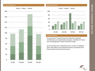
40. MARKETSUMMARYANALYSIS
Market Distribution1st Year Sales Figures
Our perennial 3rd Quarter boost was larger than expected
contributing to an exceptionally strong year. Distribution of sales
across the geographic markets looks fairly steady.
Our new product line, released this year, is early in its adoption
phase. We expect to see substantial revenue contribution from
these products over the next two years.
Financial Summary
0
20
40
60
80
100
1st Qtr 2nd Qtr 3rd Qtr 4th Qtr
East West North
0
20
40
60
80
100
120
140
160
180
1st Qtr 2nd Qtr 3rd Qtr 4th Qtr
East West North
41. BUSINESSSUMMARY
Market Share by Division
Product Division 2002 2003 2004 2005
Electronics 10.3 % 12.1% 13.2% 17.0%
Consumer Goods 1.3% 2.3% 2.2% 2.7%
Services 12.0% 11.0% 8.9% 9.2%
Widget Sales 78.0% 82.3% 82.5% 84.0%
Installations 5.3% 7.9% 12.2% 15.1%
(1) Percentages based on domestic comparison to competitors in directly related
industries.
(2) Percentages based on standing at the end of each fiscal year.
(3) Values provided by a third party agency.
Organizational Structure
Contoso
Product
Development
Design Manufacturing
Quality
Assurance
Human
Resources
Headquarters Subsidiaries
Finance
Business Process Model
Summary
This has been a pivotal year for the company in growth, but also
development of our infrastructure and business processes. We’ll
continue to focus on our internal systems over the next year.
Specific growth areas include Electronics where Contoso has seen
as 6.7% increase in market share over the last three years. An area
to monitor closely is the Services division where market share has
dropped slightly.
Operating
Supporting
Optimizing
Changing