SlideShare a Scribd company logo
2.1
Chapter 2
Network Models
Copyright © The McGraw-Hill Companies, Inc. Permission required for reproduction or display.
2.2
2-1 LAYERED TASKS
We use the concept of layers in our daily life. As an
example, let us consider two friends who communicate
through postal mail. The process of sending a letter to a
friend would be complex if there were no services
available from the post office.
Sender, Receiver, and Carrier
Hierarchy
Topics discussed in this section:
2.3
Figure 2.1 Tasks involved in sending a letter
2.4
2-2 THE OSI MODEL
Established in 1947, the International Standards
Organization (ISO) is a multinational body dedicated to
worldwide agreement on international standards. An ISO
standard that covers all aspects of network
communications is the Open Systems Interconnection
(OSI) model. It was first introduced in the late 1970s.
Layered Architecture
Peer-to-Peer Processes
Encapsulation
Topics discussed in this section:
2.5
ISO is the organization.
OSI is the model.
Note
2.6
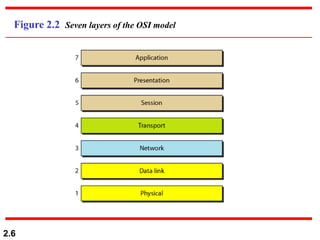
Figure 2.2 Seven layers of the OSI model
2.7
Figure 2.3 The interaction between layers in the OSI model
2.8
Figure 2.4 An exchange using the OSI model
2.9
2-3 LAYERS IN THE OSI MODEL
In this section we briefly describe the functions of each
layer in the OSI model.
Physical Layer
Data Link Layer
Network Layer
Transport Layer
Session Layer
Presentation Layer
Application Layer
Topics discussed in this section:
2.10
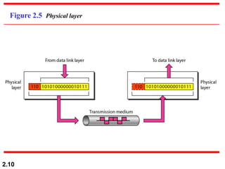
Figure 2.5 Physical layer
2.11
The physical layer is responsible for movements of
individual bits from one hop (node) to the next.
Note
2.12
Figure 2.6 Data link layer
2.13
The data link layer is responsible for moving
frames from one hop (node) to the next.
Note
2.14
Figure 2.7 Hop-to-hop delivery
2.15
Figure 2.8 Network layer
2.16
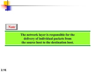
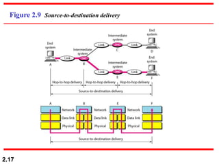
The network layer is responsible for the
delivery of individual packets from
the source host to the destination host.
Note
2.17
Figure 2.9 Source-to-destination delivery
2.18
Figure 2.10 Transport layer
2.19
The transport layer is responsible for the delivery
of a message from one process to another.
Note
2.20
Figure 2.11 Reliable process-to-process delivery of a message
2.21
Figure 2.12 Session layer
2.22
The session layer is responsible for dialog
control and synchronization.
Note
2.23
Figure 2.13 Presentation layer
2.24
The presentation layer is responsible for translation,
compression, and encryption.
Note
2.25
Figure 2.14 Application layer
2.26
The application layer is responsible for
providing services to the user.
Note
2.27
Figure 2.15 Summary of layers
2.28
2-4 TCP/IP PROTOCOL SUITE
The layers in the TCP/IP protocol suite do not exactly
match those in the OSI model. The original TCP/IP
protocol suite was defined as having four layers: host-to-
network, internet, transport, and application. However,
when TCP/IP is compared to OSI, we can say that the
TCP/IP protocol suite is made of five layers: physical,
data link, network, transport, and application.
Physical and Data Link Layers
Network Layer
Transport Layer
Application Layer
Topics discussed in this section:
2.29
Figure 2.16 TCP/IP and OSI model
2.30
2-5 ADDRESSING
Four levels of addresses are used in an internet employing
the TCP/IP protocols: physical, logical, port, and specific.
Physical Addresses
Logical Addresses
Port Addresses
Specific Addresses
Topics discussed in this section:
2.31
Figure 2.17 Addresses in TCP/IP
2.32
Figure 2.18 Relationship of layers and addresses in TCP/IP
2.33
In Figure 2.19 a node with physical address 10 sends a
frame to a node with physical address 87. The two nodes
are connected by a link (bus topology LAN). As the
figure shows, the computer with physical address 10 is
the sender, and the computer with physical address 87 is
the receiver.
Example 2.1
2.34
Figure 2.19 Physical addresses
2.35
Most local-area networks use a 48-bit (6-byte) physical
address written as 12 hexadecimal digits; every byte (2
hexadecimal digits) is separated by a colon, as shown
below:
Example 2.2
07:01:02:01:2C:4B
A 6-byte (12 hexadecimal digits) physical address.
2.36
Figure 2.20 shows a part of an internet with two routers
connecting three LANs. Each device (computer or
router) has a pair of addresses (logical and physical) for
each connection. In this case, each computer is
connected to only one link and therefore has only one
pair of addresses. Each router, however, is connected to
three networks (only two are shown in the figure). So
each router has three pairs of addresses, one for each
connection.
Example 2.3
2.37
Figure 2.20 IP addresses
2.38
Figure 2.21 shows two computers communicating via the
Internet. The sending computer is running three
processes at this time with port addresses a, b, and c. The
receiving computer is running two processes at this time
with port addresses j and k. Process a in the sending
computer needs to communicate with process j in the
receiving computer. Note that although physical
addresses change from hop to hop, logical and port
addresses remain the same from the source to
destination.
Example 2.4
2.39
Figure 2.21 Port addresses
2.40
The physical addresses will change from hop to hop,
but the logical addresses usually remain the same.
Note
2.41
Example 2.5
A port address is a 16-bit address represented by one
decimal number as shown.
753
A 16-bit port address represented
as one single number.
More Related Content

Similar to ANAND1.ppt (18)

PPT
Chapter 2
Faisal Mehmood
 
PPT
Chapter 2 - Network Models
Wayne Jones Jnr
 
PPT
Unit-1 Layers in Computer Networks and Protocols
jagmohankr2648
 
PPT
Data communicationand networking _ network models.ppt
SowaibaKhan1
 
PPT
ch2_v1.ppt55556667777888999.............
subhadipmalakar981
 
PPT
ch2_v1.pptkkkkkkkkkkkkkkkkkkkkkkkkkkkkkkkk
sitalamalakar108
 
PPT
Introduction to data communication system.ppt
dilipmandloi7
 
PPT
Introduction to data communication_v1.ppt
dilipmandloi7
 
PPT
Open_system_interconnection_document1.ppt
bhavyatripathi7
 
PPT
ch2_v1.ppt networking tertyui fdcfjgfybvuu
adnanshaheen425
 
PDF
CCN lecture 2 on computer communication and networking
pragyapandey8984
 
PPT
02 Network Models
Ahmar Hashmi
 
PPT
Ch02
Vivek Kumar
 
PPT
Network Models in Networking.
Mohammad Uzair Akram 
 
PPT
Data communication and networking with network module
SafiUllah130
 
PPT
ch02.ppt
FahimJahangir1
 
Chapter 2
Faisal Mehmood
 
Chapter 2 - Network Models
Wayne Jones Jnr
 
Unit-1 Layers in Computer Networks and Protocols
jagmohankr2648
 
Data communicationand networking _ network models.ppt
SowaibaKhan1
 
ch2_v1.ppt55556667777888999.............
subhadipmalakar981
 
ch2_v1.pptkkkkkkkkkkkkkkkkkkkkkkkkkkkkkkkk
sitalamalakar108
 
Introduction to data communication system.ppt
dilipmandloi7
 
Introduction to data communication_v1.ppt
dilipmandloi7
 
Open_system_interconnection_document1.ppt
bhavyatripathi7
 
ch2_v1.ppt networking tertyui fdcfjgfybvuu
adnanshaheen425
 
CCN lecture 2 on computer communication and networking
pragyapandey8984
 
02 Network Models
Ahmar Hashmi
 
Network Models in Networking.
Mohammad Uzair Akram 
 
Data communication and networking with network module
SafiUllah130
 
ch02.ppt
FahimJahangir1
 

Recently uploaded (20)

PPTX
原版一样(Acadia毕业证书)加拿大阿卡迪亚大学毕业证办理方法
Taqyea
 
PPTX
artificial intelligence applications in Geomatics
NawrasShatnawi1
 
PPTX
MobileComputingMANET2023 MobileComputingMANET2023.pptx
masterfake98765
 
PDF
Introduction to Productivity and Quality
মোঃ ফুরকান উদ্দিন জুয়েল
 
PPT
Carmon_Remote Sensing GIS by Mahesh kumar
DhananjayM6
 
PPTX
Mechanical Design of shell and tube heat exchangers as per ASME Sec VIII Divi...
shahveer210504
 
PPTX
What is Shot Peening | Shot Peening is a Surface Treatment Process
Vibra Finish
 
DOC
MRRS Strength and Durability of Concrete
CivilMythili
 
PDF
Biomechanics of Gait: Engineering Solutions for Rehabilitation (www.kiu.ac.ug)
publication11
 
PPTX
Server Side Web Development Unit 1 of Nodejs.pptx
sneha852132
 
PPTX
Lecture 1 Shell and Tube Heat exchanger-1.pptx
mailforillegalwork
 
PDF
Basic_Concepts_in_Clinical_Biochemistry_2018كيمياء_عملي.pdf
AdelLoin
 
PPTX
DATA BASE MANAGEMENT AND RELATIONAL DATA
gomathisankariv2
 
PDF
Water Industry Process Automation & Control Monthly July 2025
Water Industry Process Automation & Control
 
PDF
MAD Unit - 2 Activity and Fragment Management in Android (Diploma IT)
JappanMavani
 
PDF
Ethics and Trustworthy AI in Healthcare – Governing Sensitive Data, Profiling...
AlqualsaDIResearchGr
 
PDF
AI TECHNIQUES FOR IDENTIFYING ALTERATIONS IN THE HUMAN GUT MICROBIOME IN MULT...
vidyalalltv1
 
PPTX
Day2 B2 Best.pptx
helenjenefa1
 
PDF
GTU Civil Engineering All Semester Syllabus.pdf
Vimal Bhojani
 
PDF
Zilliz Cloud Demo for performance and scale
Zilliz
 
原版一样(Acadia毕业证书)加拿大阿卡迪亚大学毕业证办理方法
Taqyea
 
artificial intelligence applications in Geomatics
NawrasShatnawi1
 
MobileComputingMANET2023 MobileComputingMANET2023.pptx
masterfake98765
 
Introduction to Productivity and Quality
মোঃ ফুরকান উদ্দিন জুয়েল
 
Carmon_Remote Sensing GIS by Mahesh kumar
DhananjayM6
 
Mechanical Design of shell and tube heat exchangers as per ASME Sec VIII Divi...
shahveer210504
 
What is Shot Peening | Shot Peening is a Surface Treatment Process
Vibra Finish
 
MRRS Strength and Durability of Concrete
CivilMythili
 
Biomechanics of Gait: Engineering Solutions for Rehabilitation (www.kiu.ac.ug)
publication11
 
Server Side Web Development Unit 1 of Nodejs.pptx
sneha852132
 
Lecture 1 Shell and Tube Heat exchanger-1.pptx
mailforillegalwork
 
Basic_Concepts_in_Clinical_Biochemistry_2018كيمياء_عملي.pdf
AdelLoin
 
DATA BASE MANAGEMENT AND RELATIONAL DATA
gomathisankariv2
 
Water Industry Process Automation & Control Monthly July 2025
Water Industry Process Automation & Control
 
MAD Unit - 2 Activity and Fragment Management in Android (Diploma IT)
JappanMavani
 
Ethics and Trustworthy AI in Healthcare – Governing Sensitive Data, Profiling...
AlqualsaDIResearchGr
 
AI TECHNIQUES FOR IDENTIFYING ALTERATIONS IN THE HUMAN GUT MICROBIOME IN MULT...
vidyalalltv1
 
Day2 B2 Best.pptx
helenjenefa1
 
GTU Civil Engineering All Semester Syllabus.pdf
Vimal Bhojani
 
Zilliz Cloud Demo for performance and scale
Zilliz
 

ANAND1.ppt

  • 1. 2.1 Chapter 2 Network Models Copyright © The McGraw-Hill Companies, Inc. Permission required for reproduction or display.
  • 2. 2.2 2-1 LAYERED TASKS We use the concept of layers in our daily life. As an example, let us consider two friends who communicate through postal mail. The process of sending a letter to a friend would be complex if there were no services available from the post office. Sender, Receiver, and Carrier Hierarchy Topics discussed in this section:
  • 3. 2.3 Figure 2.1 Tasks involved in sending a letter
  • 4. 2.4 2-2 THE OSI MODEL Established in 1947, the International Standards Organization (ISO) is a multinational body dedicated to worldwide agreement on international standards. An ISO standard that covers all aspects of network communications is the Open Systems Interconnection (OSI) model. It was first introduced in the late 1970s. Layered Architecture Peer-to-Peer Processes Encapsulation Topics discussed in this section:
  • 5. 2.5 ISO is the organization. OSI is the model. Note
  • 6. 2.6 Figure 2.2 Seven layers of the OSI model
  • 7. 2.7 Figure 2.3 The interaction between layers in the OSI model
  • 8. 2.8 Figure 2.4 An exchange using the OSI model
  • 9. 2.9 2-3 LAYERS IN THE OSI MODEL In this section we briefly describe the functions of each layer in the OSI model. Physical Layer Data Link Layer Network Layer Transport Layer Session Layer Presentation Layer Application Layer Topics discussed in this section:
  • 11. 2.11 The physical layer is responsible for movements of individual bits from one hop (node) to the next. Note
  • 12. 2.12 Figure 2.6 Data link layer
  • 13. 2.13 The data link layer is responsible for moving frames from one hop (node) to the next. Note
  • 16. 2.16 The network layer is responsible for the delivery of individual packets from the source host to the destination host. Note
  • 19. 2.19 The transport layer is responsible for the delivery of a message from one process to another. Note
  • 20. 2.20 Figure 2.11 Reliable process-to-process delivery of a message
  • 22. 2.22 The session layer is responsible for dialog control and synchronization. Note
  • 24. 2.24 The presentation layer is responsible for translation, compression, and encryption. Note
  • 26. 2.26 The application layer is responsible for providing services to the user. Note
  • 28. 2.28 2-4 TCP/IP PROTOCOL SUITE The layers in the TCP/IP protocol suite do not exactly match those in the OSI model. The original TCP/IP protocol suite was defined as having four layers: host-to- network, internet, transport, and application. However, when TCP/IP is compared to OSI, we can say that the TCP/IP protocol suite is made of five layers: physical, data link, network, transport, and application. Physical and Data Link Layers Network Layer Transport Layer Application Layer Topics discussed in this section:
  • 29. 2.29 Figure 2.16 TCP/IP and OSI model
  • 30. 2.30 2-5 ADDRESSING Four levels of addresses are used in an internet employing the TCP/IP protocols: physical, logical, port, and specific. Physical Addresses Logical Addresses Port Addresses Specific Addresses Topics discussed in this section:
  • 32. 2.32 Figure 2.18 Relationship of layers and addresses in TCP/IP
  • 33. 2.33 In Figure 2.19 a node with physical address 10 sends a frame to a node with physical address 87. The two nodes are connected by a link (bus topology LAN). As the figure shows, the computer with physical address 10 is the sender, and the computer with physical address 87 is the receiver. Example 2.1
  • 35. 2.35 Most local-area networks use a 48-bit (6-byte) physical address written as 12 hexadecimal digits; every byte (2 hexadecimal digits) is separated by a colon, as shown below: Example 2.2 07:01:02:01:2C:4B A 6-byte (12 hexadecimal digits) physical address.
  • 36. 2.36 Figure 2.20 shows a part of an internet with two routers connecting three LANs. Each device (computer or router) has a pair of addresses (logical and physical) for each connection. In this case, each computer is connected to only one link and therefore has only one pair of addresses. Each router, however, is connected to three networks (only two are shown in the figure). So each router has three pairs of addresses, one for each connection. Example 2.3
  • 37. 2.37 Figure 2.20 IP addresses
  • 38. 2.38 Figure 2.21 shows two computers communicating via the Internet. The sending computer is running three processes at this time with port addresses a, b, and c. The receiving computer is running two processes at this time with port addresses j and k. Process a in the sending computer needs to communicate with process j in the receiving computer. Note that although physical addresses change from hop to hop, logical and port addresses remain the same from the source to destination. Example 2.4
  • 40. 2.40 The physical addresses will change from hop to hop, but the logical addresses usually remain the same. Note
  • 41. 2.41 Example 2.5 A port address is a 16-bit address represented by one decimal number as shown. 753 A 16-bit port address represented as one single number.