SlideShare a Scribd company logo
1
ABSTRACT
Our proposed system allows sensing of various parameters at our home, it enables automation
of various devices connected to a single Arduino board which is programmed to fulfil the
requirements of a person. System uses variables for pins connected to temperature sensor, fan,
ultrasonic distance sensor, outdoor ambient light sensor, burglar detection system and for
trigger and echo pins.
The system constantly transmits this data to the Arduino board, which processes this data and
keeps on checking it against the provided code for desired output. This data is live updated to
be viewed on the online server system. Also, system allows user to set alerts for particular
instances or emergencies too.
2
1. Basics of Arduino Programming
Arduino is an open-source electronics platform based on easy-to-use hardware and software.
Arduino boards are able to read inputs - light on a sensor, a finger on a button, or a Twitter
message, activating a motor, turning on an LED, publishing something online. We can tell our
board what to do by sending a set of instructions to the microcontroller on the board.
Arduino was born at the Ivrea Interaction Design Institute as an easy tool for fast prototyping,
aimed at students without a background in electronics and programming.
Over the years Arduino has been the brain of thousands of projects, from everyday objects to
complex scientific instruments. A worldwide community of makers - students, hobbyists,
artists, programmers, and professionals - has gathered around this open-source platform, their
contributions have added up to an incredible amount of accessible knowledge that can be of
great help to novices and experts alike.
The Arduino software is easy-to-use for beginners, yet flexible enough for advanced users. It
runs on Mac, Windows, and Linux. Teachers and students use it to build low cost scientific
instruments, to prove chemistry and physics principles, or to get started with programming and
robotics. Designers and architects build interactive prototypes, musicians and artists use it for
installations and to experiment with new musical instruments.
Arduino has the following advantages over other devices:
 Inexpensive - Arduino boards are relatively inexpensive compared to other
microcontroller platforms. The least expensive version of the Arduino module can be
assembled by hand, and even the pre-assembled Arduino modules cost less than $50
 Cross-platform - The Arduino Software (IDE) runs on Windows, Macintosh OSX, and
Linux operating systems. Most microcontroller systems are limited to Windows.
 Simple, clear programming environment - The Arduino Software (IDE) is easy-to-
use for beginners, yet flexible enough for advanced users to take advantage of as well.
For teachers, it's conveniently based on the Processing programming environment, so
students learning to program in that environment will be familiar with how the Arduino
IDE works.
 Open source and extensible software - The Arduino software is published as open-
source tools, available for extension by experienced programmers. The language can
be expanded through C++ libraries, and people wanting to understand the technical
details can make the leap from Arduino to the AVR C programming language on which
it's based. Similarly, you can add AVR-C code directly into your Arduino programs if
you want to.
 Open source and extensible hardware - The plans of the Arduino boards are
published under a Creative Commons license, so experienced circuit designers can
make their own version of the module, extending it and improving it. Even relatively
inexperienced users can build the breadboard version of the module in order to
understand how it works and save money.
3
Languages Used in Arduino
The Arduino board is connected to a computer via USB, where it connects with the Arduino
development environment (IDE). The user writes the Arduino code in the IDE, then uploads
it to the microcontroller which executes the code, interacting with inputs and outputs such
as sensors, motors, and lights.
Arduino code is written in C++ with an addition of special methods and functions, C++ is
a human-readable programming language. When you create a ‘sketch’ (the name given to
Arduino code files), it is processed and compiled to machine language.
In case of need we can use other languages for Arduino Programming too like Node.js
Code using Johnny Five Project, Python Code using pyserial, Go Code with Gobot etc.
In Arduino Programming language, a program is known as Sketch, Sketch is always saved
with the. ino extension, there are two major functions in Arduino Code, we can have more
than two functions also as per necessity.
Code structure of an Arduino program consists of following elements:
 Libraries - In Arduino, much like other leading programming platforms, there are
built-in libraries that provide basic functionality. In addition, it’s possible to import
other libraries and expand the Arduino board capabilities and features. These
libraries are roughly divided into libraries that interact with a specific component
or those that implement new functions.
 Pin Definitions - To use the Arduino pins, you need to define which pin is being
used and its functionality. A convenient way to define the used pins is by using:
‘#define pinName pinNumber’. The functionality is either input or output and is
defined by using the pinMode () method in the setup section.
 Variables - Whenever you’re using Arduino, you need to declare global variables
and instances to be used later on. In a nutshell, a variable allows you to name and
store a value to be used in the future. To declare a variable, you simply define its
type, name and initial value. It’s worth mentioning that declaring global variables
isn’t an absolute necessity.
 Instances - In software programming, a class is a collection of functions and
variables that are kept together in one place. Each class has a special function known
as a constructor, which is used to create an instance of the class.
 Setup() Function - Every Arduino sketch must have a setup function. This function
defines the initial state of the Arduino upon boot and runs only once. Here we’ll
define the following:
1. Pin functionality using the pinMode function
2. Initial state of pins
3. Initialize classes
4. Initialize variables
5. Code logic
 Loop () - The loop function is also a must for every Arduino sketch and executes
once setup () is complete. It is the main function and as its name hints, it runs in a
loop over and over again. The loop describes the main logic of your circuit.
4
A Sample and Circuit for LED glow (Tinker CAD Simulator):
Circuit:
The given circuit shows us
the connections of Arduino
board to the LED bulbs so
that they can glow We know
that the Arduino Board has
Pins for Vin, 5V, 3.3V,
GND, Reset, PWM, Analog
Pins, Digital Pins, Serial
Pins, SPI Pins, Led Pin etc.
The code for the given
circuit can be given as:
Code:
Link: https://www.tinkercad.com/things/gwbAJzNvkzl
5
Sketch consists of several methods which are used to perform particular tasks, these methods
can be designed as per user’s needs. A basic circuit to print ‘Hello world’ on console can be
simply given as: -
Arduino pins are by default configured as inputs, so they do not need to be explicitly declared
as inputs with pinMode () when you are using them as inputs. Pins configured this way are said
to be in a high-impedance state. Present and fixed information that can be programmed exactly
as it is used is termed as Literal. A collection of characters is referred to as String. Strings can
be represented using ‘’ or “” signs. Programming language provides two functions pinMode ()
and digitalWrite (), these functions enable us to set the logic values at pins to high or low. The
pinMode () function is used to configure a specific pin to behave either as an input or an output.
It is possible to enable the internal pull-up resistors with the mode INPUT_PULLUP.
Additionally, the INPUT mode explicitly disables the internal pull-ups.
Syntax of pinMode function is:
Void setup () {
pinMode (pin, mode);
}
where pin gives the number of the pin whose mode you wish to set and mode can be INPUT,
OUTPUT, or INPUT_PULLUP.
The digitalWrite () function is used to write a HIGH or a LOW value to a digital pin. If the pin
has been configured as an OUTPUT with pinMode (), its voltage will be set to the
corresponding value: 5V (or 3.3V on 3.3V boards) for HIGH, 0V (ground) for LOW. If the pin
is configured as an INPUT, digitalWrite () will enable (HIGH) or disable (LOW) the internal
pullup on the input pin. It is recommended to set the pinMode () to INPUT_PULLUP to enable
the internal pull-up resistor.
Syntax of digitalWrite () function is:
Void loop () {
digitalWrite (pin, value);
}
where pin gives the number of the pin whose mode you wish to set and value can be set to
HIGH, or LOW.
6
In the lower-right part of the Arduino board, you will see six pins marked “Analog In”. These
special pins not only tell whether there is a voltage applied to them, but also its value. By using
the analogRead () function, we can read the voltage applied to one of the pins This function
returns a number between 0 and 1023, which represents voltages between 0 and 5 volts. For
example, if there is a voltage of 2.5 V applied to pin number 0, analogRead (0) returns 512.
Syntax of analogRead () function is:
analogRead(pin);
where pin gives the number of the analog input pin to read from (0 to 5 on most boards, 0 to 7
on the Mini and Nano, 0 to 15 on the Mega)
CONTROL STATEMENTS
Decision making structures require that the programmer specify one or more conditions to be
evaluated or tested by the program. It should be along with a statement or statements to be
executed if the condition is determined to be true, and optionally, other statements to be
executed if the condition is determined to be false.
 If statement - It takes an expression in parenthesis and a statement or block of
statements. If the expression is true then the statement or block of statements gets
executed otherwise these statements are skipped.
 If …else statement - An if statement can be followed by an optional else statement,
which executes when the expression is false.
 If…else if …else statement - The if statement can be followed by an optional else
if...else statement, which is very useful to test various conditions using single
if...else if statement.
 switch case statement - Similar to the if statements, switch...case controls the flow
of programs by allowing the programmers to specify different codes that should be
executed in various conditions.
 Conditional Operator - The conditional operator ‘?’: is the only ternary operator in
C.
LOOPS
Programming languages provide various control structures that allow for more complicated
execution paths. A loop statement allows us to execute a statement or group of statements
multiple times There are following loops in C programming language:
 While loop - While loops will loop continuously, and infinitely, until the expression
inside the parenthesis, () becomes false. Something must change the tested variable, or
the while loop will never exit.
 Do…while loop - The do…while loop is similar to the while loop. In the while loop,
the loop-continuation condition is tested at the beginning of the loop before performed
the body of the loop.
 For loop - A for loop executes statements a predetermined number of times. The control
expression for the loop is initialized, tested and manipulated entirely within the for loop
parentheses.
7
 Nested loop - C language allows you to use one loop inside another loop. The following
example illustrates the concept.
 Infinite loop - It is the loop having no terminating condition, so the loop becomes
infinite.
SERIAL COMMUNICATION
Serial communication on pins TX/RX uses TTL logic levels (5V or 3.3V depending on the
board). Don't connect these pins directly to an RS232 serial port; they operate at +/- 12V and
can damage your Arduino board. Serial is used for communication between the Arduino board
and a computer or other devices. All Arduino boards have at least one serial port (also known
as a UART or USART): Serial. It communicates on digital pins 0 (RX) and 1 (TX) as well as
with the computer via USB. Thus, if you use these functions, you cannot also use pins 0 and 1
for digital input or output.
Functions available on serial communication are: if(Serial), available(), begin(), end(), flush(),
print(), println(), read(), readString(), write(), serialEvent(), all these functions are used to
perform various operations like reading each character from the serial monitor or print
characters on serial monitor etc.
TONE
The turning on and then turning off of something that moves the air is called Tone, number of
vibrations per second is called frequency. A speaker is a device with a coil of wire suspended
near a permanent magnet, the wire is glued to paper cone called diaphragm, electric current
creates magnetic field that pushes against that of magnet causing the cone to move. Arduino is
a digital device that is why the tone which is a sine wave, is represented as a half square wave
in it. tone () is the most prominent function in an Arduino tone library, it generates a square
wave of the specified frequency (and 50% duty cycle) on a pin. A duration can be specified,
otherwise the wave continues until a call to noTone (). The pin can be connected to a piezo
buzzer or other speaker to play tones. Only one tone can be generated at a time. If a tone is
already playing on a different pin, the call to tone () will have no effect. If the tone is playing
on the same pin, the call will set its frequency. Use of the tone () function will interfere with
PWM output on pins 3 and 11 (on boards other than the Mega).
Syntax of tone function is:
tone (pin, frequency)
tone (pin, frequency, duration)
where pin gives the Arduino pin on which to generate the tone, frequency is the frequency of
the tone in hertz (Allowed data types: unsigned int) and duration gives the duration of the tone
in milliseconds (optional). (Allowed data types: unsigned long).
8
2. Basics of Electronics
OHM’S LAW
It states that the voltage across a conductor is proportional to current through it provided the
physical conditions like voltage, current etc. remain constant
V = IR
OR I = V/R
A short circuit is a circuit element whose resistance is approaching zero while closed circuit is
a circuit element whose resistance is approaching infinity. To make a proper Arduino circuit it
is essential to know minimum and maximum voltages for various devices as sometimes lower
currents at sufficient voltages might not be able to drive the devices like LEDs etc. while high
currents might burn the devices.
RESISTANCE AND CAPACITORS
Resistor is a two terminal passive electronic device which is used to resist the flow of current,
they are used to reduce current flow, divide voltage and adjust signal flows. In series the current
across all resistors is zero, and voltages add up to main supply voltages, while in parallel circuit
voltage across all resistors is same and current adds up to supply current.
Req = R1+R2+R3+… in series while in parallel 1/Req = 1/R1+ 1/R2 + 1/R3+…
A device that stores electrical energy in electric field is called capacitor, it is a passive element
and its effect is known as capacitance. When capacitors are in parallel, they have same voltage
across them and the equivalent capacitance can be calculated by adding up all three
capacitances and when capacitances are in series, they have the same charge on them and thus
their equivalent capacitance can be calculated by adding up their reciprocals.
Ceq = 1/C1 + 1/ C2 + 1/C3 +… when in series and Ceq = C1+C2+C3
Capacitors are used for Energy storage, power factor correction, suppression and coupling,
signal coupling and decoupling and in high pass and low pass filters.
A Breadboard is a solderless device which is used for making temporary prototype of a circuit.
Most electronic components can be connected with a breadboard, adjacent pins are connected
in horizontal and vertical way and multiple pins provide the same potential.
9
Light-emitting diode (LED) is a widely used standard source of light in electrical equipment.
It has a wide range of applications ranging from your mobile phone to large advertising
billboards. They mostly find applications in devices that show the time and display different
types of data. LEDs emit light when an electric current flows through it. When current passes
through an LED, the electrons recombine with holes emitting light in the process. LEDs allow
the current to flow in the forward direction and blocks the current in the reverse direction.
Light-emitting diodes are heavily doped p-n junctions. Based on the semiconductor material
used and the amount of doping, an LED will emit a coloured light at a particular spectral
wavelength when forward biased.
When the diode is forward biased, the minority electrons are sent from p → n while the
minority holes are sent from n → p. At the junction boundary, the concentration of minority
carriers increases. The excess minority carriers at the junction recombine with the majority
charges carriers. The energy is released in the form of photons on recombination. In standard
diodes, the energy is released in the form of heat. But in light-emitting diodes, the energy is
released in the form of photons. We call this phenomenon electroluminescence.
Electroluminescence is an optical phenomenon, and electrical phenomenon where a material
emits light in response to an electric current passed through it. As the forward voltage
increases, the intensity of the light increases and reaches a maximum.
The 7-segment display, also written as “seven segment display”, consists of seven LEDs
(hence its name) arranged in a rectangular fashion as shown. Each of the seven LEDs is
called a segment because when illuminated the segment forms part of a numerical digit (both
Decimal and Hex) to be displayed. An additional 8th LED is sometimes used within the same
package thus allowing the indication of a decimal point, (DP) when two or more 7-segment
displays are connected together to display numbers greater than ten.
10
Each one of the seven LEDs in the display is
given a positional segment with one of its
connection pins being brought straight out of
the rectangular plastic package. These
individually LED pins are labelled from a
through to g representing each individual
LED. The other LED pins are connected
together and wired to form a common pin. So,
by forward biasing the appropriate pins of the
LED segments in a particular order, some
segments will be light and others will be dark
allowing the desired character pattern of the number to be generated on the display. This then
allows us to display each of the ten decimal digits 0 through to 9 on the same 7-segment
display.
LCD (Liquid Crystal Display) is a type of flat panel display which uses liquid crystals in its
primary form of operation. LEDs have a large and varying set of use cases for consumers and
businesses, as they can be commonly found in smartphones, televisions, computer monitors
and instrument panels. LCDs were a big leap in terms of the technology they replaced, which
include light-emitting diode (LED) and gas-plasma displays. LCDs allowed displays to be
much thinner than cathode ray tube (CRT) technology. LCDs consume much less power than
LED and gas-display displays because they work on the principle of blocking light rather
than emitting it. Where an LED emits light, the liquid crystals in an LCD produces an image
using a backlight. A display is made up of millions of pixels. The quality of a display
commonly refers to the number of pixels; for example, a 4K display is made up of 3840
x2160 or 4096x2160 pixels. A pixel is made up of three subpixels; a red, blue and green—
commonly called RGB. When the subpixels in a pixel change colour combinations, a
different colour can be produced. With all the pixels on a display working together, the
display can make millions of different colours. When the pixels are rapidly switched on and
off, a picture is created. The way a pixel is controlled is different in each type of display;
CRT, LED, LCD and newer types of displays all control pixels differently. In short, LCDs
are lit by a backlight, and pixels are switched on and off electronically while using liquid
crystals to rotate polarized light. A polarizing glass filter is placed in front and behind all the
pixels, the front filter is placed at
90 degrees. In between both filters
are the liquid crystals, which can be
electronically switched on and off.
LCDs are made with either a
passive matrix or an active-matrix
display grid. The active-matrix
LCD is also known as a thin film
transistor (TFT) display. The
passive matrix LCD has a grid of
conductors with pixels located at
each intersection in the grid. A
current is sent across two
conductors on the grid to control
11
the light for any pixel. An active matrix has a transistor located at each pixel intersection,
requiring less current to control the luminance of a pixel.
A DC motor is any of a class of rotary electrical motors that converts direct current electrical
energy into mechanical energy. The most common types rely on the forces produced by
magnetic fields. Nearly all types of DC motors have some internal mechanism, either
electromechanical or electronic, to periodically change the direction of current in part of the
motor. DC motors were the first form of motor widely used, as they could be powered from
existing direct-current lighting power distribution systems. A DC motor's speed can be
controlled over a wide range, using either a variable supply voltage or by changing the
strength of current in its field windings. Small DC motors are used in tools, toys, and
appliances. The universal motor can operate on direct current but is a lightweight brushed
motor used for portable power tools and appliances. Larger DC motors are currently used in
propulsion of electric vehicles, elevator and hoists, and in drives for steel rolling mills. The
advent of power electronics has made replacement of DC motors with AC motors possible in
many applications. A coil of wire with a current running through it generates an
electromagnetic field aligned with the centre of the coil. The direction and magnitude of the
magnetic field produced by the coil can be changed with the direction and magnitude of the
current flowing through it. A simple DC motor has a
stationary set of magnets in the stator and an armature
with one or more windings of insulated wire wrapped
around a soft iron core that concentrates the magnetic
field. The windings usually have multiple turns around
the core, and in large motors there can be several
parallel current paths. The ends of the wire winding
are connected to a commutator. The commutator
allows each armature coil to be energized in turn and
connects the rotating coils with the external power
supply through brushes. (Brushless DC motors have
electronics that switch the DC current to each coil on
and off and have no brushes.)
A servomotor (or servo motor) is a rotary actuator or linear actuator that allows for precise
control of angular or linear position, velocity and acceleration. It consists of a suitable motor
coupled to a sensor for position feedback. It also requires a relatively sophisticated controller,
often a dedicated module designed specifically for use with servomotors. Servomotors are not
a specific class of motor, although the term servomotor is often used to refer to a motor
suitable for use in a closed-loop control system. Servomotors are used in applications such as
robotics, CNC machinery, and automated manufacturing. A servomotor is a closed-loop
servomechanism that uses position feedback to control its motion and final position. The
input to its control is a signal (either analogue or digital) representing the position
commanded for the output shaft. The motor is paired with some type of position encoder to
provide position and speed feedback. In the simplest case, only the position is measured. The
measured position of the output is compared to the command position, the external input to
the controller. If the output position differs from that required, an error signal is generated
which then causes the motor to rotate in either direction, as needed to bring the output shaft to
the appropriate position. As the positions approach, the error signal reduces to zero and the
12
motor stops. The very simplest servomotors use position-only sensing via a potentiometer
and bang-bang control of their motor; the motor always rotates at full speed (or is stopped).
This type of servomotor is not widely used in industrial motion control, but it forms the basis
of the simple and cheap servos used for radio-controlled models. More sophisticated
servomotors use optical rotary encoders to measure the speed of the output shaft] and a
variable-speed drive to control the motor speed.] Both of these enhancements, usually in
combination with a PID control algorithm, allow the servomotor to be brought to its
commanded position more quickly and more precisely, with less overshooting. Servomotors
are generally used as a high-performance alternative to the stepper motor. Stepper motors
have some inherent ability to control position, as they have built-in output steps. This often
allows them to be used as an open-loop position control, without any feedback encoder, as
their drive signal specifies the number of steps of movement to rotate, but for this the
controller needs to 'know' the position of the
stepper motor on power up. Therefore, on first
power up, the controller will have to activate the
stepper motor and turn it to a known position, e.g.
until it activates an end limit switch. This can be
observed when switching on an inkjet printer; the
controller will move the ink jet carrier to the
extreme left and right to establish the end positions.
A servomotor will immediately turn to whatever
angle the controller instructs it to, regardless of the
initial position at power up.
13
3. Interfacing basic Input Output Devices
I. RGB Led Blink Circuit
Components – Arduino Uno R3, LED RGB, 330Ω Resistor
Circuit -
Code –
14
II. DC Motor Control Circuit
Components – Hobby Gearmotor, Arduino Uno R3, H-Bridge Motor Driver
Circuit-
Code-
15
III. L.D.R Light detector Circuit
Components- Arduino Uno R3, Photoresistor, 1kΩ resistor, Voltage Multimeter
Circuit-
Code-
16
IV. Ultrasonic Sensor Circuit
Components- Arduino Uno R3, 330Ω Resistor, Ultrasonic Distance Sensor, White LED
Circuit-
Code-
17
V. Temperature Sensor Circuit
Components- Temperature sensor (TMP36), Piezoelectric Buzzer, Arduino Uno R3
Circuit-
Code-
18
VI. Gas Sensor Circuit
Components- Arduino Uno R3, Gas Sensor, Piezo electric buzzer, 4kΩ and 1kΩ resistors
Circuit-
Code-
VII. PIR Sensor Circuit
Components-Arduino Uno R3, 34,-156.541 PIR sensor, Voltage Multimeter, Red LED, 420Ω
Resistor
19
Circuit-
Code-
VIII. Flex Sensor Circuit
Components-Flex sensor, Arduino Uno R3, red LED, 400Ω resistor, 80kΩ resistor
20
Circuit-
Code-
21
IX. 4×4 Keypad Circuit
Components-Keypad 4×4, Arduino Uno R3
Circuit-
Code-
22
4. Mini Projects
I. Smart Street Light – The circuit consists of a light bulb illustrating street light, which turns
off during day automatically and turns on during night, this function is performed by a light
detecting resistance.
Components- Ambient Light sensor (Phototransistor), Relay SPDT, Light Bulb, Arduino Uno
R3, 9V Battery, 1KΩ resistor
Circuit-
Code-
23
II. Water Level Detection
Components-Ultrasonic Distance Sensor, Red LED, Arduino Uno R3, Piezoelectric Buzzer,
DC motor, Relay SPDT, 220Ω resistor
Circuit-
Code-
24
III. Burglar Detection Alarm
Components-Arduino Uno R3, Piezoelectric Buzzer, -2.15 -211.66 PIR Sensor, pushbutton,
250kΩ potentiometer, 1kΩ resistor
Circuit-
Code-
25
IV. Keypad password Protected Door
Components-keypad 4×4, micro servo motors, Arduino Uno R3
26
Circuit-
Code-
27
V. Fire Fighting Robot
Components- Photoresistor, Hobby Gearmotor, Arduino Uno R3, DC motor, 1kΩ resistor
28
Circuit-
Code-
29
30
5. Final Project
Home Automation System
The system allows user to automate various devices at home and at the same time provides
the facility of setting alerts at various instances. The system makes use of various kinds of
sensors altogether at once for example temperature sensor, fan, burglar detection system,
buzzer, ultrasonic distance sensor etc.
Circuit -
Code –
#include <LiquidCrystal.h>
int tempVal = A2;
int fan = 13; (setting variables to record various parameters)
int AmbSen = 0;
int outdoor = 5;
long distance;
int duration;
int Burglar = 0;
int trig=7;
int echo=6;
LiquidCrystal lcd (12, 11, 9, 8, A3, A4);
void setup ()
{
Serial.begin(9600);
pinMode (fan, OUTPUT);
31
pinMode (outdoor, OUTPUT);
pinMode (tempVal, INPUT);
pinMode (A0, INPUT);
pinMode (4, INPUT);
pinMode (A5, OUTPUT);
pinMode (2, OUTPUT);
pinMode (7, OUTPUT);
pinMode (6, INPUT);
attachInterrupt (digitalPinToInterrupt (3), stop, CHANGE);
}
void loop ()
{
// Fan
float temp = analogRead(A2);
temp = (temp * 0.48828125) - 49;
lcd.clear();
lcd.print ("Temperature: ");
Serial.print("Temperature: ");
Serial.print(temp);
lcd.print(temp);
Serial.println(" C");
lcd. println (" C");
delay (100);
if (temp > 28)
{
digitalWrite (fan, HIGH);
delay (100);
}
else if ((temp > 23) && (temp < 28))
{
digitalWrite (fan, HIGH);
delay (100);
}
else
{
digitalWrite (fan, LOW);
Serial.print("Temperature: ");
delay (100);
}
// Automated Outdoor Light
AmbSen = analogRead(A0);
Serial.println(AmbSen);
if (AmbSen < 400)
{
digitalWrite (outdoor, HIGH);
delay (100);
}
else
32
{
digitalWrite (outdoor, LOW);
delay (100);
}
// Burglar Detection
Burglar = digitalRead (4);
if (Burglar == HIGH)
{
digitalWrite (A5, HIGH);
delay (10000);
}
else
{
digitalWrite (A5, LOW);
delay (100);
}
// Water Level Monitoring
digitalWrite (7, HIGH);
digitalWrite (7, LOW);
duration=pulseIn (echo, HIGH);
distance=duration*(0.034/2);
if(distance>100)
{
digitalWrite (2, HIGH);
delay (100);
}
else
{
digitalWrite (2, LOW);
Serial.println(distance);
delay (100);
}
}
void stop ()
{
digitalWrite (A5, LOW);
Serial.println(distance);
delay (100);
}
Ad

More Related Content

What's hot (20)

Numerical Problems on Ampitude Modulation
Numerical Problems on Ampitude ModulationNumerical Problems on Ampitude Modulation
Numerical Problems on Ampitude Modulation
Renji K
 
Electrónica digital: capitulo 5 Circuitos combinacionales MSI
Electrónica digital: capitulo 5 Circuitos combinacionales MSI Electrónica digital: capitulo 5 Circuitos combinacionales MSI
Electrónica digital: capitulo 5 Circuitos combinacionales MSI
SANTIAGO PABLO ALBERTO
 
Engineering Electromagnetics 8th Edition Hayt Solutions Manual
Engineering Electromagnetics 8th Edition Hayt Solutions ManualEngineering Electromagnetics 8th Edition Hayt Solutions Manual
Engineering Electromagnetics 8th Edition Hayt Solutions Manual
xoreq
 
VHDL Entity
VHDL EntityVHDL Entity
VHDL Entity
Ramasubbu .P
 
VLSI DESIGN OF AMBA BASED AHB2APB BRIDGE
VLSI DESIGN OF AMBA BASED AHB2APB BRIDGEVLSI DESIGN OF AMBA BASED AHB2APB BRIDGE
VLSI DESIGN OF AMBA BASED AHB2APB BRIDGE
VLSICS Design
 
SEQUENTIAL CIRCUITS [FLIP FLOPS AND LATCHES]
SEQUENTIAL CIRCUITS [FLIP FLOPS AND LATCHES]SEQUENTIAL CIRCUITS [FLIP FLOPS AND LATCHES]
SEQUENTIAL CIRCUITS [FLIP FLOPS AND LATCHES]
SUBHA SHREE
 
Amplificador Source Comun
Amplificador Source ComunAmplificador Source Comun
Amplificador Source Comun
Bertha Vega
 
Introduction to VHDL
Introduction to VHDLIntroduction to VHDL
Introduction to VHDL
Aksum Institute of Technology(AIT, @Letsgo)
 
Multivibrators.pptx
Multivibrators.pptxMultivibrators.pptx
Multivibrators.pptx
DEVAJJI NAGARAJU
 
IC 555 timer and its applications
IC 555 timer and its applications IC 555 timer and its applications
IC 555 timer and its applications
Jay Baria
 
Current mirror-A constant current circuit
Current mirror-A constant current circuitCurrent mirror-A constant current circuit
Current mirror-A constant current circuit
Dr. Kapil Gupta
 
Original IGBT 6MBP20XSF060-50 20XSF060 060 20A 600V New Fuji
Original IGBT 6MBP20XSF060-50 20XSF060 060 20A 600V New FujiOriginal IGBT 6MBP20XSF060-50 20XSF060 060 20A 600V New Fuji
Original IGBT 6MBP20XSF060-50 20XSF060 060 20A 600V New Fuji
AUTHELECTRONIC
 
Chapter 4 flip flop for students
Chapter 4 flip flop for studentsChapter 4 flip flop for students
Chapter 4 flip flop for students
CT Sabariah Salihin
 
Load flow study Part-II
Load flow study Part-IILoad flow study Part-II
Load flow study Part-II
Asif Jamadar
 
Clippers AND Clampers
Clippers AND ClampersClippers AND Clampers
Clippers AND Clampers
JUNAID SK
 
Estudio, simulación, montaje y verificación del sistema de alimentación inint...
Estudio, simulación, montaje y verificación del sistema de alimentación inint...Estudio, simulación, montaje y verificación del sistema de alimentación inint...
Estudio, simulación, montaje y verificación del sistema de alimentación inint...
Juan Camilo Escobar Castro
 
Shift Registers.pptx
Shift Registers.pptxShift Registers.pptx
Shift Registers.pptx
AyushGupta685716
 
Arduino Uno Pin Description
Arduino Uno Pin DescriptionArduino Uno Pin Description
Arduino Uno Pin Description
Niket Chandrawanshi
 
555 TIMER IC & its APPLICATION
555 TIMER IC & its APPLICATION555 TIMER IC & its APPLICATION
555 TIMER IC & its APPLICATION
Subham Dhar
 
Read only memory(rom)
Read only memory(rom)Read only memory(rom)
Read only memory(rom)
Syed Saeed
 
Numerical Problems on Ampitude Modulation
Numerical Problems on Ampitude ModulationNumerical Problems on Ampitude Modulation
Numerical Problems on Ampitude Modulation
Renji K
 
Electrónica digital: capitulo 5 Circuitos combinacionales MSI
Electrónica digital: capitulo 5 Circuitos combinacionales MSI Electrónica digital: capitulo 5 Circuitos combinacionales MSI
Electrónica digital: capitulo 5 Circuitos combinacionales MSI
SANTIAGO PABLO ALBERTO
 
Engineering Electromagnetics 8th Edition Hayt Solutions Manual
Engineering Electromagnetics 8th Edition Hayt Solutions ManualEngineering Electromagnetics 8th Edition Hayt Solutions Manual
Engineering Electromagnetics 8th Edition Hayt Solutions Manual
xoreq
 
VLSI DESIGN OF AMBA BASED AHB2APB BRIDGE
VLSI DESIGN OF AMBA BASED AHB2APB BRIDGEVLSI DESIGN OF AMBA BASED AHB2APB BRIDGE
VLSI DESIGN OF AMBA BASED AHB2APB BRIDGE
VLSICS Design
 
SEQUENTIAL CIRCUITS [FLIP FLOPS AND LATCHES]
SEQUENTIAL CIRCUITS [FLIP FLOPS AND LATCHES]SEQUENTIAL CIRCUITS [FLIP FLOPS AND LATCHES]
SEQUENTIAL CIRCUITS [FLIP FLOPS AND LATCHES]
SUBHA SHREE
 
Amplificador Source Comun
Amplificador Source ComunAmplificador Source Comun
Amplificador Source Comun
Bertha Vega
 
IC 555 timer and its applications
IC 555 timer and its applications IC 555 timer and its applications
IC 555 timer and its applications
Jay Baria
 
Current mirror-A constant current circuit
Current mirror-A constant current circuitCurrent mirror-A constant current circuit
Current mirror-A constant current circuit
Dr. Kapil Gupta
 
Original IGBT 6MBP20XSF060-50 20XSF060 060 20A 600V New Fuji
Original IGBT 6MBP20XSF060-50 20XSF060 060 20A 600V New FujiOriginal IGBT 6MBP20XSF060-50 20XSF060 060 20A 600V New Fuji
Original IGBT 6MBP20XSF060-50 20XSF060 060 20A 600V New Fuji
AUTHELECTRONIC
 
Chapter 4 flip flop for students
Chapter 4 flip flop for studentsChapter 4 flip flop for students
Chapter 4 flip flop for students
CT Sabariah Salihin
 
Load flow study Part-II
Load flow study Part-IILoad flow study Part-II
Load flow study Part-II
Asif Jamadar
 
Clippers AND Clampers
Clippers AND ClampersClippers AND Clampers
Clippers AND Clampers
JUNAID SK
 
Estudio, simulación, montaje y verificación del sistema de alimentación inint...
Estudio, simulación, montaje y verificación del sistema de alimentación inint...Estudio, simulación, montaje y verificación del sistema de alimentación inint...
Estudio, simulación, montaje y verificación del sistema de alimentación inint...
Juan Camilo Escobar Castro
 
555 TIMER IC & its APPLICATION
555 TIMER IC & its APPLICATION555 TIMER IC & its APPLICATION
555 TIMER IC & its APPLICATION
Subham Dhar
 
Read only memory(rom)
Read only memory(rom)Read only memory(rom)
Read only memory(rom)
Syed Saeed
 

Similar to Arduino and Circuits.docx (20)

Ch_2_8,9,10.pptx
Ch_2_8,9,10.pptxCh_2_8,9,10.pptx
Ch_2_8,9,10.pptx
yosikit826
 
Aurdino presentation
Aurdino presentationAurdino presentation
Aurdino presentation
C.Vamsi Krishna
 
What is arduino
What is arduinoWhat is arduino
What is arduino
vivek kumar
 
Presentation of online Internship Program on Arduino completed at INTERNSHALA
Presentation of online Internship Program on Arduino completed at INTERNSHALAPresentation of online Internship Program on Arduino completed at INTERNSHALA
Presentation of online Internship Program on Arduino completed at INTERNSHALA
AviPatel16612
 
Report on arduino
Report on arduinoReport on arduino
Report on arduino
Ravi Phadtare
 
Introduction to Arduino 16822775 (2).ppt
Introduction to Arduino 16822775 (2).pptIntroduction to Arduino 16822775 (2).ppt
Introduction to Arduino 16822775 (2).ppt
ansariparveen06
 
Arduino Programming Basic
Arduino Programming BasicArduino Programming Basic
Arduino Programming Basic
LITS IT Ltd,LASRC.SPACE,SAWDAGOR BD,FREELANCE BD,iREV,BD LAW ACADEMY,SMART AVI,HEA,HFSAC LTD.
 
Fund. of IoT LAB - CO 252.pptx
Fund. of IoT LAB                  - CO 252.pptxFund. of IoT LAB                  - CO 252.pptx
Fund. of IoT LAB - CO 252.pptx
y22co015
 
Arduino اردوينو
Arduino اردوينوArduino اردوينو
Arduino اردوينو
salih mahmod
 
Lab Manual Arduino UNO Microcontrollar.docx
Lab Manual Arduino UNO Microcontrollar.docxLab Manual Arduino UNO Microcontrollar.docx
Lab Manual Arduino UNO Microcontrollar.docx
RashidFaridChishti
 
Arduino: Arduino starter kit
Arduino: Arduino starter kitArduino: Arduino starter kit
Arduino: Arduino starter kit
SANTIAGO PABLO ALBERTO
 
arduino and its introduction deep dive ppt.pptx
arduino and its introduction deep dive ppt.pptxarduino and its introduction deep dive ppt.pptx
arduino and its introduction deep dive ppt.pptx
SruSru1
 
Embedded system programming using Arduino microcontroller
Embedded system programming using Arduino microcontrollerEmbedded system programming using Arduino microcontroller
Embedded system programming using Arduino microcontroller
Arun Kumar
 
Lab 2_ Programming an Arduino.pdf
Lab 2_ Programming an Arduino.pdfLab 2_ Programming an Arduino.pdf
Lab 2_ Programming an Arduino.pdf
ssuser0e9cc4
 
Arduino day 2019
Arduino day 2019Arduino day 2019
Arduino day 2019
BIPUL KUMAR GUPTA
 
1.Arduino Ecosystem.pptx
1.Arduino Ecosystem.pptx1.Arduino Ecosystem.pptx
1.Arduino Ecosystem.pptx
Mohamed Essam
 
Microcontroller Programming & Hardware Introduction
Microcontroller Programming & Hardware IntroductionMicrocontroller Programming & Hardware Introduction
Microcontroller Programming & Hardware Introduction
Joseph Sanchez
 
Lecture 7
Lecture 7Lecture 7
Lecture 7
vishal choudhary
 
Arduino IDE
Arduino IDE Arduino IDE
Arduino IDE
Mrunal Deshkar
 
Embedded system application
Embedded system applicationEmbedded system application
Embedded system application
Dhruwank Vankawala
 
Ch_2_8,9,10.pptx
Ch_2_8,9,10.pptxCh_2_8,9,10.pptx
Ch_2_8,9,10.pptx
yosikit826
 
Presentation of online Internship Program on Arduino completed at INTERNSHALA
Presentation of online Internship Program on Arduino completed at INTERNSHALAPresentation of online Internship Program on Arduino completed at INTERNSHALA
Presentation of online Internship Program on Arduino completed at INTERNSHALA
AviPatel16612
 
Introduction to Arduino 16822775 (2).ppt
Introduction to Arduino 16822775 (2).pptIntroduction to Arduino 16822775 (2).ppt
Introduction to Arduino 16822775 (2).ppt
ansariparveen06
 
Fund. of IoT LAB - CO 252.pptx
Fund. of IoT LAB                  - CO 252.pptxFund. of IoT LAB                  - CO 252.pptx
Fund. of IoT LAB - CO 252.pptx
y22co015
 
Arduino اردوينو
Arduino اردوينوArduino اردوينو
Arduino اردوينو
salih mahmod
 
Lab Manual Arduino UNO Microcontrollar.docx
Lab Manual Arduino UNO Microcontrollar.docxLab Manual Arduino UNO Microcontrollar.docx
Lab Manual Arduino UNO Microcontrollar.docx
RashidFaridChishti
 
arduino and its introduction deep dive ppt.pptx
arduino and its introduction deep dive ppt.pptxarduino and its introduction deep dive ppt.pptx
arduino and its introduction deep dive ppt.pptx
SruSru1
 
Embedded system programming using Arduino microcontroller
Embedded system programming using Arduino microcontrollerEmbedded system programming using Arduino microcontroller
Embedded system programming using Arduino microcontroller
Arun Kumar
 
Lab 2_ Programming an Arduino.pdf
Lab 2_ Programming an Arduino.pdfLab 2_ Programming an Arduino.pdf
Lab 2_ Programming an Arduino.pdf
ssuser0e9cc4
 
1.Arduino Ecosystem.pptx
1.Arduino Ecosystem.pptx1.Arduino Ecosystem.pptx
1.Arduino Ecosystem.pptx
Mohamed Essam
 
Microcontroller Programming & Hardware Introduction
Microcontroller Programming & Hardware IntroductionMicrocontroller Programming & Hardware Introduction
Microcontroller Programming & Hardware Introduction
Joseph Sanchez
 
Ad

Recently uploaded (20)

Microsoft Office 365 Crack Latest Version 2025?
Microsoft Office 365 Crack Latest Version 2025?Microsoft Office 365 Crack Latest Version 2025?
Microsoft Office 365 Crack Latest Version 2025?
yousfhashmi786
 
chapter hshs jsjshs sjjsjs kenshs kensh.pptx
chapter hshs jsjshs sjjsjs kenshs kensh.pptxchapter hshs jsjshs sjjsjs kenshs kensh.pptx
chapter hshs jsjshs sjjsjs kenshs kensh.pptx
vvghgjgf
 
Bone Tubeoudgkaitaurauraurarhafhau4rculosis.pptx
Bone   Tubeoudgkaitaurauraurarhafhau4rculosis.pptxBone   Tubeoudgkaitaurauraurarhafhau4rculosis.pptx
Bone Tubeoudgkaitaurauraurarhafhau4rculosis.pptx
gaisga4er
 
>parallel desktop Crack Latest Free 2025 | PPT
>parallel desktop Crack Latest Free 2025 | PPT>parallel desktop Crack Latest Free 2025 | PPT
>parallel desktop Crack Latest Free 2025 | PPT
yousfhashmi786
 
TabulationwjsnnanamamamNananaka of Data.pptx
TabulationwjsnnanamamamNananaka of Data.pptxTabulationwjsnnanamamamNananaka of Data.pptx
TabulationwjsnnanamamamNananaka of Data.pptx
sriyansh4443
 
MiniTool Partition Wizard Professional Edition 10.2.1 Crack
MiniTool Partition Wizard Professional Edition 10.2.1 CrackMiniTool Partition Wizard Professional Edition 10.2.1 Crack
MiniTool Partition Wizard Professional Edition 10.2.1 Crack
yousfhashmi786
 
Download Capcut Pro 5.7.1.2152 Crack Latest Version | PPT
Download Capcut Pro 5.7.1.2152 Crack Latest Version | PPTDownload Capcut Pro 5.7.1.2152 Crack Latest Version | PPT
Download Capcut Pro 5.7.1.2152 Crack Latest Version | PPT
yousfhashmi786
 
荷兰代尔夫特理工大学毕业证书文凭定制TUDelft成绩单定制
荷兰代尔夫特理工大学毕业证书文凭定制TUDelft成绩单定制荷兰代尔夫特理工大学毕业证书文凭定制TUDelft成绩单定制
荷兰代尔夫特理工大学毕业证书文凭定制TUDelft成绩单定制
Taqyea
 
Informe mensual Marzo sobre el informe de un servicio
Informe mensual Marzo sobre el informe de un servicioInforme mensual Marzo sobre el informe de un servicio
Informe mensual Marzo sobre el informe de un servicio
serviciotecnico65
 
00804.pptvjlvpuvupvpyvupv6v07upv60v7vupv0v6p
00804.pptvjlvpuvupvpyvupv6v07upv60v7vupv0v6p00804.pptvjlvpuvupvpyvupv6v07upv60v7vupv0v6p
00804.pptvjlvpuvupvpyvupv6v07upv60v7vupv0v6p
hkrishna9495
 
linearly separable and therefore a set of weights exist that are consistent ...
linearly separable and therefore a set of weights exist that are consistent  ...linearly separable and therefore a set of weights exist that are consistent  ...
linearly separable and therefore a set of weights exist that are consistent ...
mebibek_hu
 
Auslogics File Recovery Professional 12.0.1 Crack New Version Latest 2025
Auslogics File Recovery Professional 12.0.1 Crack New Version Latest 2025Auslogics File Recovery Professional 12.0.1 Crack New Version Latest 2025
Auslogics File Recovery Professional 12.0.1 Crack New Version Latest 2025
usmankhan66g66
 
materi semi konduktor untuk belajar elektronika daya
materi semi konduktor untuk belajar elektronika dayamateri semi konduktor untuk belajar elektronika daya
materi semi konduktor untuk belajar elektronika daya
RaidahAuliaMursyid
 
OSPF & DHCP PPT.pptx it is relATED TO NETWORKING
OSPF & DHCP PPT.pptx it is relATED TO NETWORKINGOSPF & DHCP PPT.pptx it is relATED TO NETWORKING
OSPF & DHCP PPT.pptx it is relATED TO NETWORKING
ritikghw
 
AnyDesk 5.2.1 Crack License Key Full Version 2019 {Latest}
AnyDesk 5.2.1 Crack License Key Full Version 2019 {Latest}AnyDesk 5.2.1 Crack License Key Full Version 2019 {Latest}
AnyDesk 5.2.1 Crack License Key Full Version 2019 {Latest}
yousfhashmi786
 
ADRENAL CORTbsbsbshEX 3 & 4 - 22MBBS.pptx
ADRENAL CORTbsbsbshEX 3 & 4 - 22MBBS.pptxADRENAL CORTbsbsbshEX 3 & 4 - 22MBBS.pptx
ADRENAL CORTbsbsbshEX 3 & 4 - 22MBBS.pptx
c2422429
 
Spectrophotometer instrument basics -.pptx
Spectrophotometer instrument basics -.pptxSpectrophotometer instrument basics -.pptx
Spectrophotometer instrument basics -.pptx
muthulakshmitc
 
Multilingual hand gesture to speech conversion system
Multilingual hand gesture to speech conversion systemMultilingual hand gesture to speech conversion system
Multilingual hand gesture to speech conversion system
Himabindu905359
 
Linepro - Product Profile- Capacitive Panels
Linepro - Product Profile- Capacitive PanelsLinepro - Product Profile- Capacitive Panels
Linepro - Product Profile- Capacitive Panels
PaulMalpan1
 
High Perfomance and Reliability Inverter
High Perfomance and Reliability InverterHigh Perfomance and Reliability Inverter
High Perfomance and Reliability Inverter
CarlosFranco13613
 
Microsoft Office 365 Crack Latest Version 2025?
Microsoft Office 365 Crack Latest Version 2025?Microsoft Office 365 Crack Latest Version 2025?
Microsoft Office 365 Crack Latest Version 2025?
yousfhashmi786
 
chapter hshs jsjshs sjjsjs kenshs kensh.pptx
chapter hshs jsjshs sjjsjs kenshs kensh.pptxchapter hshs jsjshs sjjsjs kenshs kensh.pptx
chapter hshs jsjshs sjjsjs kenshs kensh.pptx
vvghgjgf
 
Bone Tubeoudgkaitaurauraurarhafhau4rculosis.pptx
Bone   Tubeoudgkaitaurauraurarhafhau4rculosis.pptxBone   Tubeoudgkaitaurauraurarhafhau4rculosis.pptx
Bone Tubeoudgkaitaurauraurarhafhau4rculosis.pptx
gaisga4er
 
>parallel desktop Crack Latest Free 2025 | PPT
>parallel desktop Crack Latest Free 2025 | PPT>parallel desktop Crack Latest Free 2025 | PPT
>parallel desktop Crack Latest Free 2025 | PPT
yousfhashmi786
 
TabulationwjsnnanamamamNananaka of Data.pptx
TabulationwjsnnanamamamNananaka of Data.pptxTabulationwjsnnanamamamNananaka of Data.pptx
TabulationwjsnnanamamamNananaka of Data.pptx
sriyansh4443
 
MiniTool Partition Wizard Professional Edition 10.2.1 Crack
MiniTool Partition Wizard Professional Edition 10.2.1 CrackMiniTool Partition Wizard Professional Edition 10.2.1 Crack
MiniTool Partition Wizard Professional Edition 10.2.1 Crack
yousfhashmi786
 
Download Capcut Pro 5.7.1.2152 Crack Latest Version | PPT
Download Capcut Pro 5.7.1.2152 Crack Latest Version | PPTDownload Capcut Pro 5.7.1.2152 Crack Latest Version | PPT
Download Capcut Pro 5.7.1.2152 Crack Latest Version | PPT
yousfhashmi786
 
荷兰代尔夫特理工大学毕业证书文凭定制TUDelft成绩单定制
荷兰代尔夫特理工大学毕业证书文凭定制TUDelft成绩单定制荷兰代尔夫特理工大学毕业证书文凭定制TUDelft成绩单定制
荷兰代尔夫特理工大学毕业证书文凭定制TUDelft成绩单定制
Taqyea
 
Informe mensual Marzo sobre el informe de un servicio
Informe mensual Marzo sobre el informe de un servicioInforme mensual Marzo sobre el informe de un servicio
Informe mensual Marzo sobre el informe de un servicio
serviciotecnico65
 
00804.pptvjlvpuvupvpyvupv6v07upv60v7vupv0v6p
00804.pptvjlvpuvupvpyvupv6v07upv60v7vupv0v6p00804.pptvjlvpuvupvpyvupv6v07upv60v7vupv0v6p
00804.pptvjlvpuvupvpyvupv6v07upv60v7vupv0v6p
hkrishna9495
 
linearly separable and therefore a set of weights exist that are consistent ...
linearly separable and therefore a set of weights exist that are consistent  ...linearly separable and therefore a set of weights exist that are consistent  ...
linearly separable and therefore a set of weights exist that are consistent ...
mebibek_hu
 
Auslogics File Recovery Professional 12.0.1 Crack New Version Latest 2025
Auslogics File Recovery Professional 12.0.1 Crack New Version Latest 2025Auslogics File Recovery Professional 12.0.1 Crack New Version Latest 2025
Auslogics File Recovery Professional 12.0.1 Crack New Version Latest 2025
usmankhan66g66
 
materi semi konduktor untuk belajar elektronika daya
materi semi konduktor untuk belajar elektronika dayamateri semi konduktor untuk belajar elektronika daya
materi semi konduktor untuk belajar elektronika daya
RaidahAuliaMursyid
 
OSPF & DHCP PPT.pptx it is relATED TO NETWORKING
OSPF & DHCP PPT.pptx it is relATED TO NETWORKINGOSPF & DHCP PPT.pptx it is relATED TO NETWORKING
OSPF & DHCP PPT.pptx it is relATED TO NETWORKING
ritikghw
 
AnyDesk 5.2.1 Crack License Key Full Version 2019 {Latest}
AnyDesk 5.2.1 Crack License Key Full Version 2019 {Latest}AnyDesk 5.2.1 Crack License Key Full Version 2019 {Latest}
AnyDesk 5.2.1 Crack License Key Full Version 2019 {Latest}
yousfhashmi786
 
ADRENAL CORTbsbsbshEX 3 & 4 - 22MBBS.pptx
ADRENAL CORTbsbsbshEX 3 & 4 - 22MBBS.pptxADRENAL CORTbsbsbshEX 3 & 4 - 22MBBS.pptx
ADRENAL CORTbsbsbshEX 3 & 4 - 22MBBS.pptx
c2422429
 
Spectrophotometer instrument basics -.pptx
Spectrophotometer instrument basics -.pptxSpectrophotometer instrument basics -.pptx
Spectrophotometer instrument basics -.pptx
muthulakshmitc
 
Multilingual hand gesture to speech conversion system
Multilingual hand gesture to speech conversion systemMultilingual hand gesture to speech conversion system
Multilingual hand gesture to speech conversion system
Himabindu905359
 
Linepro - Product Profile- Capacitive Panels
Linepro - Product Profile- Capacitive PanelsLinepro - Product Profile- Capacitive Panels
Linepro - Product Profile- Capacitive Panels
PaulMalpan1
 
High Perfomance and Reliability Inverter
High Perfomance and Reliability InverterHigh Perfomance and Reliability Inverter
High Perfomance and Reliability Inverter
CarlosFranco13613
 
Ad

Arduino and Circuits.docx

  • 1. 1 ABSTRACT Our proposed system allows sensing of various parameters at our home, it enables automation of various devices connected to a single Arduino board which is programmed to fulfil the requirements of a person. System uses variables for pins connected to temperature sensor, fan, ultrasonic distance sensor, outdoor ambient light sensor, burglar detection system and for trigger and echo pins. The system constantly transmits this data to the Arduino board, which processes this data and keeps on checking it against the provided code for desired output. This data is live updated to be viewed on the online server system. Also, system allows user to set alerts for particular instances or emergencies too.
  • 2. 2 1. Basics of Arduino Programming Arduino is an open-source electronics platform based on easy-to-use hardware and software. Arduino boards are able to read inputs - light on a sensor, a finger on a button, or a Twitter message, activating a motor, turning on an LED, publishing something online. We can tell our board what to do by sending a set of instructions to the microcontroller on the board. Arduino was born at the Ivrea Interaction Design Institute as an easy tool for fast prototyping, aimed at students without a background in electronics and programming. Over the years Arduino has been the brain of thousands of projects, from everyday objects to complex scientific instruments. A worldwide community of makers - students, hobbyists, artists, programmers, and professionals - has gathered around this open-source platform, their contributions have added up to an incredible amount of accessible knowledge that can be of great help to novices and experts alike. The Arduino software is easy-to-use for beginners, yet flexible enough for advanced users. It runs on Mac, Windows, and Linux. Teachers and students use it to build low cost scientific instruments, to prove chemistry and physics principles, or to get started with programming and robotics. Designers and architects build interactive prototypes, musicians and artists use it for installations and to experiment with new musical instruments. Arduino has the following advantages over other devices:  Inexpensive - Arduino boards are relatively inexpensive compared to other microcontroller platforms. The least expensive version of the Arduino module can be assembled by hand, and even the pre-assembled Arduino modules cost less than $50  Cross-platform - The Arduino Software (IDE) runs on Windows, Macintosh OSX, and Linux operating systems. Most microcontroller systems are limited to Windows.  Simple, clear programming environment - The Arduino Software (IDE) is easy-to- use for beginners, yet flexible enough for advanced users to take advantage of as well. For teachers, it's conveniently based on the Processing programming environment, so students learning to program in that environment will be familiar with how the Arduino IDE works.  Open source and extensible software - The Arduino software is published as open- source tools, available for extension by experienced programmers. The language can be expanded through C++ libraries, and people wanting to understand the technical details can make the leap from Arduino to the AVR C programming language on which it's based. Similarly, you can add AVR-C code directly into your Arduino programs if you want to.  Open source and extensible hardware - The plans of the Arduino boards are published under a Creative Commons license, so experienced circuit designers can make their own version of the module, extending it and improving it. Even relatively inexperienced users can build the breadboard version of the module in order to understand how it works and save money.
  • 3. 3 Languages Used in Arduino The Arduino board is connected to a computer via USB, where it connects with the Arduino development environment (IDE). The user writes the Arduino code in the IDE, then uploads it to the microcontroller which executes the code, interacting with inputs and outputs such as sensors, motors, and lights. Arduino code is written in C++ with an addition of special methods and functions, C++ is a human-readable programming language. When you create a ‘sketch’ (the name given to Arduino code files), it is processed and compiled to machine language. In case of need we can use other languages for Arduino Programming too like Node.js Code using Johnny Five Project, Python Code using pyserial, Go Code with Gobot etc. In Arduino Programming language, a program is known as Sketch, Sketch is always saved with the. ino extension, there are two major functions in Arduino Code, we can have more than two functions also as per necessity. Code structure of an Arduino program consists of following elements:  Libraries - In Arduino, much like other leading programming platforms, there are built-in libraries that provide basic functionality. In addition, it’s possible to import other libraries and expand the Arduino board capabilities and features. These libraries are roughly divided into libraries that interact with a specific component or those that implement new functions.  Pin Definitions - To use the Arduino pins, you need to define which pin is being used and its functionality. A convenient way to define the used pins is by using: ‘#define pinName pinNumber’. The functionality is either input or output and is defined by using the pinMode () method in the setup section.  Variables - Whenever you’re using Arduino, you need to declare global variables and instances to be used later on. In a nutshell, a variable allows you to name and store a value to be used in the future. To declare a variable, you simply define its type, name and initial value. It’s worth mentioning that declaring global variables isn’t an absolute necessity.  Instances - In software programming, a class is a collection of functions and variables that are kept together in one place. Each class has a special function known as a constructor, which is used to create an instance of the class.  Setup() Function - Every Arduino sketch must have a setup function. This function defines the initial state of the Arduino upon boot and runs only once. Here we’ll define the following: 1. Pin functionality using the pinMode function 2. Initial state of pins 3. Initialize classes 4. Initialize variables 5. Code logic  Loop () - The loop function is also a must for every Arduino sketch and executes once setup () is complete. It is the main function and as its name hints, it runs in a loop over and over again. The loop describes the main logic of your circuit.
  • 4. 4 A Sample and Circuit for LED glow (Tinker CAD Simulator): Circuit: The given circuit shows us the connections of Arduino board to the LED bulbs so that they can glow We know that the Arduino Board has Pins for Vin, 5V, 3.3V, GND, Reset, PWM, Analog Pins, Digital Pins, Serial Pins, SPI Pins, Led Pin etc. The code for the given circuit can be given as: Code: Link: https://www.tinkercad.com/things/gwbAJzNvkzl
  • 5. 5 Sketch consists of several methods which are used to perform particular tasks, these methods can be designed as per user’s needs. A basic circuit to print ‘Hello world’ on console can be simply given as: - Arduino pins are by default configured as inputs, so they do not need to be explicitly declared as inputs with pinMode () when you are using them as inputs. Pins configured this way are said to be in a high-impedance state. Present and fixed information that can be programmed exactly as it is used is termed as Literal. A collection of characters is referred to as String. Strings can be represented using ‘’ or “” signs. Programming language provides two functions pinMode () and digitalWrite (), these functions enable us to set the logic values at pins to high or low. The pinMode () function is used to configure a specific pin to behave either as an input or an output. It is possible to enable the internal pull-up resistors with the mode INPUT_PULLUP. Additionally, the INPUT mode explicitly disables the internal pull-ups. Syntax of pinMode function is: Void setup () { pinMode (pin, mode); } where pin gives the number of the pin whose mode you wish to set and mode can be INPUT, OUTPUT, or INPUT_PULLUP. The digitalWrite () function is used to write a HIGH or a LOW value to a digital pin. If the pin has been configured as an OUTPUT with pinMode (), its voltage will be set to the corresponding value: 5V (or 3.3V on 3.3V boards) for HIGH, 0V (ground) for LOW. If the pin is configured as an INPUT, digitalWrite () will enable (HIGH) or disable (LOW) the internal pullup on the input pin. It is recommended to set the pinMode () to INPUT_PULLUP to enable the internal pull-up resistor. Syntax of digitalWrite () function is: Void loop () { digitalWrite (pin, value); } where pin gives the number of the pin whose mode you wish to set and value can be set to HIGH, or LOW.
  • 6. 6 In the lower-right part of the Arduino board, you will see six pins marked “Analog In”. These special pins not only tell whether there is a voltage applied to them, but also its value. By using the analogRead () function, we can read the voltage applied to one of the pins This function returns a number between 0 and 1023, which represents voltages between 0 and 5 volts. For example, if there is a voltage of 2.5 V applied to pin number 0, analogRead (0) returns 512. Syntax of analogRead () function is: analogRead(pin); where pin gives the number of the analog input pin to read from (0 to 5 on most boards, 0 to 7 on the Mini and Nano, 0 to 15 on the Mega) CONTROL STATEMENTS Decision making structures require that the programmer specify one or more conditions to be evaluated or tested by the program. It should be along with a statement or statements to be executed if the condition is determined to be true, and optionally, other statements to be executed if the condition is determined to be false.  If statement - It takes an expression in parenthesis and a statement or block of statements. If the expression is true then the statement or block of statements gets executed otherwise these statements are skipped.  If …else statement - An if statement can be followed by an optional else statement, which executes when the expression is false.  If…else if …else statement - The if statement can be followed by an optional else if...else statement, which is very useful to test various conditions using single if...else if statement.  switch case statement - Similar to the if statements, switch...case controls the flow of programs by allowing the programmers to specify different codes that should be executed in various conditions.  Conditional Operator - The conditional operator ‘?’: is the only ternary operator in C. LOOPS Programming languages provide various control structures that allow for more complicated execution paths. A loop statement allows us to execute a statement or group of statements multiple times There are following loops in C programming language:  While loop - While loops will loop continuously, and infinitely, until the expression inside the parenthesis, () becomes false. Something must change the tested variable, or the while loop will never exit.  Do…while loop - The do…while loop is similar to the while loop. In the while loop, the loop-continuation condition is tested at the beginning of the loop before performed the body of the loop.  For loop - A for loop executes statements a predetermined number of times. The control expression for the loop is initialized, tested and manipulated entirely within the for loop parentheses.
  • 7. 7  Nested loop - C language allows you to use one loop inside another loop. The following example illustrates the concept.  Infinite loop - It is the loop having no terminating condition, so the loop becomes infinite. SERIAL COMMUNICATION Serial communication on pins TX/RX uses TTL logic levels (5V or 3.3V depending on the board). Don't connect these pins directly to an RS232 serial port; they operate at +/- 12V and can damage your Arduino board. Serial is used for communication between the Arduino board and a computer or other devices. All Arduino boards have at least one serial port (also known as a UART or USART): Serial. It communicates on digital pins 0 (RX) and 1 (TX) as well as with the computer via USB. Thus, if you use these functions, you cannot also use pins 0 and 1 for digital input or output. Functions available on serial communication are: if(Serial), available(), begin(), end(), flush(), print(), println(), read(), readString(), write(), serialEvent(), all these functions are used to perform various operations like reading each character from the serial monitor or print characters on serial monitor etc. TONE The turning on and then turning off of something that moves the air is called Tone, number of vibrations per second is called frequency. A speaker is a device with a coil of wire suspended near a permanent magnet, the wire is glued to paper cone called diaphragm, electric current creates magnetic field that pushes against that of magnet causing the cone to move. Arduino is a digital device that is why the tone which is a sine wave, is represented as a half square wave in it. tone () is the most prominent function in an Arduino tone library, it generates a square wave of the specified frequency (and 50% duty cycle) on a pin. A duration can be specified, otherwise the wave continues until a call to noTone (). The pin can be connected to a piezo buzzer or other speaker to play tones. Only one tone can be generated at a time. If a tone is already playing on a different pin, the call to tone () will have no effect. If the tone is playing on the same pin, the call will set its frequency. Use of the tone () function will interfere with PWM output on pins 3 and 11 (on boards other than the Mega). Syntax of tone function is: tone (pin, frequency) tone (pin, frequency, duration) where pin gives the Arduino pin on which to generate the tone, frequency is the frequency of the tone in hertz (Allowed data types: unsigned int) and duration gives the duration of the tone in milliseconds (optional). (Allowed data types: unsigned long).
  • 8. 8 2. Basics of Electronics OHM’S LAW It states that the voltage across a conductor is proportional to current through it provided the physical conditions like voltage, current etc. remain constant V = IR OR I = V/R A short circuit is a circuit element whose resistance is approaching zero while closed circuit is a circuit element whose resistance is approaching infinity. To make a proper Arduino circuit it is essential to know minimum and maximum voltages for various devices as sometimes lower currents at sufficient voltages might not be able to drive the devices like LEDs etc. while high currents might burn the devices. RESISTANCE AND CAPACITORS Resistor is a two terminal passive electronic device which is used to resist the flow of current, they are used to reduce current flow, divide voltage and adjust signal flows. In series the current across all resistors is zero, and voltages add up to main supply voltages, while in parallel circuit voltage across all resistors is same and current adds up to supply current. Req = R1+R2+R3+… in series while in parallel 1/Req = 1/R1+ 1/R2 + 1/R3+… A device that stores electrical energy in electric field is called capacitor, it is a passive element and its effect is known as capacitance. When capacitors are in parallel, they have same voltage across them and the equivalent capacitance can be calculated by adding up all three capacitances and when capacitances are in series, they have the same charge on them and thus their equivalent capacitance can be calculated by adding up their reciprocals. Ceq = 1/C1 + 1/ C2 + 1/C3 +… when in series and Ceq = C1+C2+C3 Capacitors are used for Energy storage, power factor correction, suppression and coupling, signal coupling and decoupling and in high pass and low pass filters. A Breadboard is a solderless device which is used for making temporary prototype of a circuit. Most electronic components can be connected with a breadboard, adjacent pins are connected in horizontal and vertical way and multiple pins provide the same potential.
  • 9. 9 Light-emitting diode (LED) is a widely used standard source of light in electrical equipment. It has a wide range of applications ranging from your mobile phone to large advertising billboards. They mostly find applications in devices that show the time and display different types of data. LEDs emit light when an electric current flows through it. When current passes through an LED, the electrons recombine with holes emitting light in the process. LEDs allow the current to flow in the forward direction and blocks the current in the reverse direction. Light-emitting diodes are heavily doped p-n junctions. Based on the semiconductor material used and the amount of doping, an LED will emit a coloured light at a particular spectral wavelength when forward biased. When the diode is forward biased, the minority electrons are sent from p → n while the minority holes are sent from n → p. At the junction boundary, the concentration of minority carriers increases. The excess minority carriers at the junction recombine with the majority charges carriers. The energy is released in the form of photons on recombination. In standard diodes, the energy is released in the form of heat. But in light-emitting diodes, the energy is released in the form of photons. We call this phenomenon electroluminescence. Electroluminescence is an optical phenomenon, and electrical phenomenon where a material emits light in response to an electric current passed through it. As the forward voltage increases, the intensity of the light increases and reaches a maximum. The 7-segment display, also written as “seven segment display”, consists of seven LEDs (hence its name) arranged in a rectangular fashion as shown. Each of the seven LEDs is called a segment because when illuminated the segment forms part of a numerical digit (both Decimal and Hex) to be displayed. An additional 8th LED is sometimes used within the same package thus allowing the indication of a decimal point, (DP) when two or more 7-segment displays are connected together to display numbers greater than ten.
  • 10. 10 Each one of the seven LEDs in the display is given a positional segment with one of its connection pins being brought straight out of the rectangular plastic package. These individually LED pins are labelled from a through to g representing each individual LED. The other LED pins are connected together and wired to form a common pin. So, by forward biasing the appropriate pins of the LED segments in a particular order, some segments will be light and others will be dark allowing the desired character pattern of the number to be generated on the display. This then allows us to display each of the ten decimal digits 0 through to 9 on the same 7-segment display. LCD (Liquid Crystal Display) is a type of flat panel display which uses liquid crystals in its primary form of operation. LEDs have a large and varying set of use cases for consumers and businesses, as they can be commonly found in smartphones, televisions, computer monitors and instrument panels. LCDs were a big leap in terms of the technology they replaced, which include light-emitting diode (LED) and gas-plasma displays. LCDs allowed displays to be much thinner than cathode ray tube (CRT) technology. LCDs consume much less power than LED and gas-display displays because they work on the principle of blocking light rather than emitting it. Where an LED emits light, the liquid crystals in an LCD produces an image using a backlight. A display is made up of millions of pixels. The quality of a display commonly refers to the number of pixels; for example, a 4K display is made up of 3840 x2160 or 4096x2160 pixels. A pixel is made up of three subpixels; a red, blue and green— commonly called RGB. When the subpixels in a pixel change colour combinations, a different colour can be produced. With all the pixels on a display working together, the display can make millions of different colours. When the pixels are rapidly switched on and off, a picture is created. The way a pixel is controlled is different in each type of display; CRT, LED, LCD and newer types of displays all control pixels differently. In short, LCDs are lit by a backlight, and pixels are switched on and off electronically while using liquid crystals to rotate polarized light. A polarizing glass filter is placed in front and behind all the pixels, the front filter is placed at 90 degrees. In between both filters are the liquid crystals, which can be electronically switched on and off. LCDs are made with either a passive matrix or an active-matrix display grid. The active-matrix LCD is also known as a thin film transistor (TFT) display. The passive matrix LCD has a grid of conductors with pixels located at each intersection in the grid. A current is sent across two conductors on the grid to control
  • 11. 11 the light for any pixel. An active matrix has a transistor located at each pixel intersection, requiring less current to control the luminance of a pixel. A DC motor is any of a class of rotary electrical motors that converts direct current electrical energy into mechanical energy. The most common types rely on the forces produced by magnetic fields. Nearly all types of DC motors have some internal mechanism, either electromechanical or electronic, to periodically change the direction of current in part of the motor. DC motors were the first form of motor widely used, as they could be powered from existing direct-current lighting power distribution systems. A DC motor's speed can be controlled over a wide range, using either a variable supply voltage or by changing the strength of current in its field windings. Small DC motors are used in tools, toys, and appliances. The universal motor can operate on direct current but is a lightweight brushed motor used for portable power tools and appliances. Larger DC motors are currently used in propulsion of electric vehicles, elevator and hoists, and in drives for steel rolling mills. The advent of power electronics has made replacement of DC motors with AC motors possible in many applications. A coil of wire with a current running through it generates an electromagnetic field aligned with the centre of the coil. The direction and magnitude of the magnetic field produced by the coil can be changed with the direction and magnitude of the current flowing through it. A simple DC motor has a stationary set of magnets in the stator and an armature with one or more windings of insulated wire wrapped around a soft iron core that concentrates the magnetic field. The windings usually have multiple turns around the core, and in large motors there can be several parallel current paths. The ends of the wire winding are connected to a commutator. The commutator allows each armature coil to be energized in turn and connects the rotating coils with the external power supply through brushes. (Brushless DC motors have electronics that switch the DC current to each coil on and off and have no brushes.) A servomotor (or servo motor) is a rotary actuator or linear actuator that allows for precise control of angular or linear position, velocity and acceleration. It consists of a suitable motor coupled to a sensor for position feedback. It also requires a relatively sophisticated controller, often a dedicated module designed specifically for use with servomotors. Servomotors are not a specific class of motor, although the term servomotor is often used to refer to a motor suitable for use in a closed-loop control system. Servomotors are used in applications such as robotics, CNC machinery, and automated manufacturing. A servomotor is a closed-loop servomechanism that uses position feedback to control its motion and final position. The input to its control is a signal (either analogue or digital) representing the position commanded for the output shaft. The motor is paired with some type of position encoder to provide position and speed feedback. In the simplest case, only the position is measured. The measured position of the output is compared to the command position, the external input to the controller. If the output position differs from that required, an error signal is generated which then causes the motor to rotate in either direction, as needed to bring the output shaft to the appropriate position. As the positions approach, the error signal reduces to zero and the
  • 12. 12 motor stops. The very simplest servomotors use position-only sensing via a potentiometer and bang-bang control of their motor; the motor always rotates at full speed (or is stopped). This type of servomotor is not widely used in industrial motion control, but it forms the basis of the simple and cheap servos used for radio-controlled models. More sophisticated servomotors use optical rotary encoders to measure the speed of the output shaft] and a variable-speed drive to control the motor speed.] Both of these enhancements, usually in combination with a PID control algorithm, allow the servomotor to be brought to its commanded position more quickly and more precisely, with less overshooting. Servomotors are generally used as a high-performance alternative to the stepper motor. Stepper motors have some inherent ability to control position, as they have built-in output steps. This often allows them to be used as an open-loop position control, without any feedback encoder, as their drive signal specifies the number of steps of movement to rotate, but for this the controller needs to 'know' the position of the stepper motor on power up. Therefore, on first power up, the controller will have to activate the stepper motor and turn it to a known position, e.g. until it activates an end limit switch. This can be observed when switching on an inkjet printer; the controller will move the ink jet carrier to the extreme left and right to establish the end positions. A servomotor will immediately turn to whatever angle the controller instructs it to, regardless of the initial position at power up.
  • 13. 13 3. Interfacing basic Input Output Devices I. RGB Led Blink Circuit Components – Arduino Uno R3, LED RGB, 330Ω Resistor Circuit - Code –
  • 14. 14 II. DC Motor Control Circuit Components – Hobby Gearmotor, Arduino Uno R3, H-Bridge Motor Driver Circuit- Code-
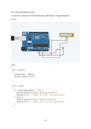
  • 15. 15 III. L.D.R Light detector Circuit Components- Arduino Uno R3, Photoresistor, 1kΩ resistor, Voltage Multimeter Circuit- Code-
  • 16. 16 IV. Ultrasonic Sensor Circuit Components- Arduino Uno R3, 330Ω Resistor, Ultrasonic Distance Sensor, White LED Circuit- Code-
  • 17. 17 V. Temperature Sensor Circuit Components- Temperature sensor (TMP36), Piezoelectric Buzzer, Arduino Uno R3 Circuit- Code-
  • 18. 18 VI. Gas Sensor Circuit Components- Arduino Uno R3, Gas Sensor, Piezo electric buzzer, 4kΩ and 1kΩ resistors Circuit- Code- VII. PIR Sensor Circuit Components-Arduino Uno R3, 34,-156.541 PIR sensor, Voltage Multimeter, Red LED, 420Ω Resistor
  • 19. 19 Circuit- Code- VIII. Flex Sensor Circuit Components-Flex sensor, Arduino Uno R3, red LED, 400Ω resistor, 80kΩ resistor
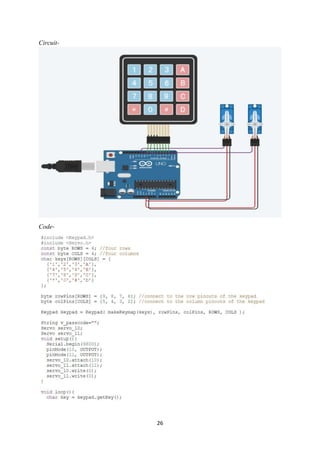
  • 21. 21 IX. 4×4 Keypad Circuit Components-Keypad 4×4, Arduino Uno R3 Circuit- Code-
  • 22. 22 4. Mini Projects I. Smart Street Light – The circuit consists of a light bulb illustrating street light, which turns off during day automatically and turns on during night, this function is performed by a light detecting resistance. Components- Ambient Light sensor (Phototransistor), Relay SPDT, Light Bulb, Arduino Uno R3, 9V Battery, 1KΩ resistor Circuit- Code-
  • 23. 23 II. Water Level Detection Components-Ultrasonic Distance Sensor, Red LED, Arduino Uno R3, Piezoelectric Buzzer, DC motor, Relay SPDT, 220Ω resistor Circuit- Code-
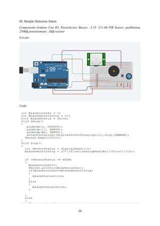
  • 24. 24 III. Burglar Detection Alarm Components-Arduino Uno R3, Piezoelectric Buzzer, -2.15 -211.66 PIR Sensor, pushbutton, 250kΩ potentiometer, 1kΩ resistor Circuit- Code-
  • 25. 25 IV. Keypad password Protected Door Components-keypad 4×4, micro servo motors, Arduino Uno R3
  • 27. 27 V. Fire Fighting Robot Components- Photoresistor, Hobby Gearmotor, Arduino Uno R3, DC motor, 1kΩ resistor
  • 29. 29
  • 30. 30 5. Final Project Home Automation System The system allows user to automate various devices at home and at the same time provides the facility of setting alerts at various instances. The system makes use of various kinds of sensors altogether at once for example temperature sensor, fan, burglar detection system, buzzer, ultrasonic distance sensor etc. Circuit - Code – #include <LiquidCrystal.h> int tempVal = A2; int fan = 13; (setting variables to record various parameters) int AmbSen = 0; int outdoor = 5; long distance; int duration; int Burglar = 0; int trig=7; int echo=6; LiquidCrystal lcd (12, 11, 9, 8, A3, A4); void setup () { Serial.begin(9600); pinMode (fan, OUTPUT);
  • 31. 31 pinMode (outdoor, OUTPUT); pinMode (tempVal, INPUT); pinMode (A0, INPUT); pinMode (4, INPUT); pinMode (A5, OUTPUT); pinMode (2, OUTPUT); pinMode (7, OUTPUT); pinMode (6, INPUT); attachInterrupt (digitalPinToInterrupt (3), stop, CHANGE); } void loop () { // Fan float temp = analogRead(A2); temp = (temp * 0.48828125) - 49; lcd.clear(); lcd.print ("Temperature: "); Serial.print("Temperature: "); Serial.print(temp); lcd.print(temp); Serial.println(" C"); lcd. println (" C"); delay (100); if (temp > 28) { digitalWrite (fan, HIGH); delay (100); } else if ((temp > 23) && (temp < 28)) { digitalWrite (fan, HIGH); delay (100); } else { digitalWrite (fan, LOW); Serial.print("Temperature: "); delay (100); } // Automated Outdoor Light AmbSen = analogRead(A0); Serial.println(AmbSen); if (AmbSen < 400) { digitalWrite (outdoor, HIGH); delay (100); } else
  • 32. 32 { digitalWrite (outdoor, LOW); delay (100); } // Burglar Detection Burglar = digitalRead (4); if (Burglar == HIGH) { digitalWrite (A5, HIGH); delay (10000); } else { digitalWrite (A5, LOW); delay (100); } // Water Level Monitoring digitalWrite (7, HIGH); digitalWrite (7, LOW); duration=pulseIn (echo, HIGH); distance=duration*(0.034/2); if(distance>100) { digitalWrite (2, HIGH); delay (100); } else { digitalWrite (2, LOW); Serial.println(distance); delay (100); } } void stop () { digitalWrite (A5, LOW); Serial.println(distance); delay (100); }