SlideShare a Scribd company logo
Button-
controlled LED
Arduino Basic
Input and Output Functions
An I/O (Input/Output) port serves as
an interface for both input and
output operations in electronic
circuits. Up until now, we have
primarily focused on the output
function, such as controlling an LED
or other external components. In this
discussion, we will explore the input
function, specifically how a
microcontroller reads the output
value of a connected device.
Push Button as an Input
Device
A push button is a common
electronic component used to
control circuits. It provides a
digital signal (HIGH or LOW)
depending on whether it is
pressed or not. When pressed,
the circuit becomes closed
(conducting state), and the
microcontroller can detect this
change.
LED as an Output Device
An LED (Light Emitting Diode)
serves as the output component
in this experiment. The
microcontroller will turn the LED
on or off based on the input
signal from the push button.
Working
Principle
1.The push button is connected to a digital
input pin of the microcontroller.
2.The LED is connected to a digital output pin.
3.When the push button is pressed, the
microcontroller detects a HIGH signal
(depending on circuit configuration) and
responds by turning the LED on.
4.When the button is released, the signal
returns to LOW, and the LED turns off.
Hardware Required
1. Uno R3 Board *1
2.USB Cable *1
3.Push Button*1
4.Red M5 LED*1
5.220Ω Resistor*1
6.10KΩ Resistor*1 7.Breadboard*1
8.Breadboard Jumper Wires* Several
Circuit Connection
Program
int ledpin = 11; // initialize pin 11 for LED
int inpin = 7; // initialize pin 7 for button
int buzzer = 9; // initialize pin 9 for buzzer
int val; // define val
void setup() {
pinMode(ledpin, OUTPUT); // set LED pin as output
pinMode(inpin, INPUT); // set button pin as input
pinMode(buzzer, OUTPUT); // set buzzer pin as output
}
void loop() {
val = digitalRead(inpin); // read the level value of pin 7 and assign it to val
if (val == LOW) { // check if the button is pressed
digitalWrite(ledpin, LOW); // turn off the LED
digitalWrite(buzzer, LOW); // turn off the buzzer
} else {
digitalWrite(ledpin, HIGH); // turn on the LED
digitalWrite(buzzer, HIGH); // turn on the buzzer
delay(100); // buzzer beeps for 100ms
digitalWrite(buzzer, LOW); // turn off the buzzer
}
}
Active Buzzer
Arduino Basic
Introduction to Active
Buzzers
Active buzzers are widely used in
various electronic applications such
as computers, printers, alarms,
electronic toys, telephones, and
timers. They function as sound-
making elements and contain an
internal vibration source. By simply
connecting an active buzzer to a 5V
power supply, it will continuously
produce sound.
Hardware Required
•Uno R3 Board 1
•USB Cable 1
•Active Buzzer 1
•Breadboard 1
•Breadboard Jumper Wires Several
Circuit Connection
Program
Sample Program
Program is simple. You control the buzzer by outputting
high/low level.
int buzzer=8;// initialize digital IO pin that controls the
buzzer
void setup()
{
pinMode(buzzer,OUTPUT);// set pin mode as “output”
}
void loop()
{
digitalWrite(buzzer, HIGH); // produce sound
delay(1000);
digitalWrite(buzzer, LOW);
delay(1000);
}
Combining led ,
button and buzzer
int ledpin = 11; // initialize pin 11 for LED
int inpin = 7; // initialize pin 7 for button
int buzzer = 9; // initialize pin 9 for buzzer
int val; // define val
void setup() {
pinMode(ledpin, OUTPUT); // set LED pin as output
pinMode(inpin, INPUT); // set button pin as input
pinMode(buzzer, OUTPUT); // set buzzer pin as output
}
void loop() {
val = digitalRead(inpin); // read the level value of pin 7 and assign it to val
if (val == LOW) { // check if the button is pressed
digitalWrite(ledpin, LOW); // turn off the LED
digitalWrite(buzzer, LOW); // turn off the buzzer
} else {
digitalWrite(ledpin, HIGH); // turn on the LED
digitalWrite(buzzer, HIGH); // turn on the buzzer
delay(100); // buzzer beeps for 100ms
digitalWrite(buzzer, LOW); // turn off the buzzer
}
}
RGB LED
Arduino Basic
Tricolor principle to display various
colors PWM controlling ports to
display full color Can be driven
directly by Arduino PWM interfaces
PWM (Pulse Width Modulation) is a technique
used to control the power supplied to electronic
components by rapidly switching the signal on
and off. The duty cycle (ratio of on-time to off-
time) determines the brightness of LEDs or the
speed of motors. In Arduino, PWM is available
on pins marked with a (~) symbol and is used
with the analogWrite() function to create
variable voltage levels for smooth dimming and
color mixing in RGB LEDs.
RGB LED
Three Primary Colors
Color mixing works because our
eyes have red, green, and blue
receptors that blend light into
different colors. By adjusting
RGB LED brightness, we trick the
eye into seeing various hues.
This same principle is used in
TVs and LCD screens, where tiny
RGB dots form images.
RGB LED connection
arduino simulators OR microcontroller.pptx
Hardware Required
• 1. Uno R3 Board *1
• 2.USB Cable *1
• 3.RGB LED *1
• 4.220Ω Resistor*3
• 5.Breadboard*1
• 6.Breadboard Jumper
Wires* Several
arduino simulators OR microcontroller.pptx
// Define RGB LED pins
const int redPin = 9;
const int greenPin = 10;
const int bluePin = 11;
void setup() {
pinMode(redPin, OUTPUT);
pinMode(greenPin, OUTPUT);
pinMode(bluePin, OUTPUT);
}
void loop() {
setColor(255, 0, 0); // Red
delay(1000);
setColor(0, 255, 0); // Green
delay(1000);
setColor(0, 0, 255); // Blue
delay(1000);
setColor(255, 255, 0); // Yellow
delay(1000);
setColor(0, 255, 255); // Cyan
delay(1000);
setColor(255, 0, 255); // Magenta
delay(1000);
setColor(255, 255, 255); // White
delay(1000);
}
// Function to set RGB color
void setColor(int red, int green, int blue) {
analogWrite(redPin, red);
analogWrite(greenPin, green);
analogWrite(bluePin, blue);
}
Simple Example
Program
Different Program
// Define RGB LED pins
int redpin = 11; // Red LED connected to pin 11
int bluepin = 10; // Blue LED connected to pin 10
int greenpin = 9; // Green LED connected to pin 9
int val; // Variable to store brightness values
void setup() {
// Set the RGB LED pins as outputs
pinMode(redpin, OUTPUT);
pinMode(bluepin, OUTPUT);
pinMode(greenpin, OUTPUT);
// Initialize serial communication at 9600 baud rate
Serial.begin(9600);
}
void loop() {
// Gradually decrease brightness from 255 to 0
for (val = 255; val > 0; val--) {
analogWrite(11, val); // Adjust Red LED brightness
analogWrite(10, 255 - val); // Adjust Blue LED brightness
inversely
analogWrite(9, 128 - val); // Adjust Green LED brightness
delay(1); // Small delay for smooth fading
}
// Gradually increase brightness from 0 to 255
for (val = 0; val < 255; val++) {
analogWrite(11, val); // Adjust Red LED brightness
analogWrite(10, 255 - val); // Adjust Blue LED brightness
inversely
analogWrite(9, 128 - val); // Adjust Green LED brightness
delay(1); // Small delay for smooth fading
}
// Print the current value of 'val' to the Serial Monitor
Serial.println(val, DEC);
}
THANK YOU!

More Related Content

Similar to arduino simulators OR microcontroller.pptx (20)

01 Intro to the Arduino and it's basics.ppt
01 Intro to the Arduino and it's basics.ppt01 Intro to the Arduino and it's basics.ppt
01 Intro to the Arduino and it's basics.ppt
pindi2197
 
arduino.ppt
arduino.pptarduino.ppt
arduino.ppt
sunilkumar652338
 
Intro to Arduino
Intro to ArduinoIntro to Arduino
Intro to Arduino
Qtechknow
 
Arduino cic3
Arduino cic3Arduino cic3
Arduino cic3
Jeni Shah
 
INTODUCTION OF IOT AND INTERFACING WITH ARDUINO UNO
INTODUCTION OF IOT AND INTERFACING WITH ARDUINO UNOINTODUCTION OF IOT AND INTERFACING WITH ARDUINO UNO
INTODUCTION OF IOT AND INTERFACING WITH ARDUINO UNO
vasankarponnapalli2
 
Arduino based applications part 1
Arduino based applications part 1Arduino based applications part 1
Arduino based applications part 1
Jawaher Abdulwahab Fadhil
 
Physical prototyping lab2-analog_digital
Physical prototyping lab2-analog_digitalPhysical prototyping lab2-analog_digital
Physical prototyping lab2-analog_digital
Tony Olsson.
 
Physical prototyping lab2-analog_digital
Physical prototyping lab2-analog_digitalPhysical prototyping lab2-analog_digital
Physical prototyping lab2-analog_digital
Tony Olsson.
 
02 General Purpose Input - Output on the Arduino
02   General Purpose Input -  Output on the Arduino02   General Purpose Input -  Output on the Arduino
02 General Purpose Input - Output on the Arduino
Wingston
 
Arduino workshop
Arduino workshopArduino workshop
Arduino workshop
Jonah Marrs
 
Fun with arduino
Fun with arduinoFun with arduino
Fun with arduino
Ravikumar Tiwari
 
02 Sensors and Actuators Understand .pdf
02 Sensors and Actuators Understand .pdf02 Sensors and Actuators Understand .pdf
02 Sensors and Actuators Understand .pdf
engsharaf2025
 
Microcontroller_basics_lesson1_2019 (1).pptx
Microcontroller_basics_lesson1_2019 (1).pptxMicrocontroller_basics_lesson1_2019 (1).pptx
Microcontroller_basics_lesson1_2019 (1).pptx
HebaEng
 
Arduino electronics cookbook
Arduino electronics cookbookArduino electronics cookbook
Arduino electronics cookbook
Felipe Belarmino
 
Arduino Workshop (3).pptx
Arduino Workshop (3).pptxArduino Workshop (3).pptx
Arduino Workshop (3).pptx
HebaEng
 
Introduction to arduino Programming with
Introduction to arduino Programming withIntroduction to arduino Programming with
Introduction to arduino Programming with
likhithkumpala159
 
Arduino workshop sensors
Arduino workshop sensorsArduino workshop sensors
Arduino workshop sensors
Jhonny Wladimir Peñaloza Cabello
 
Electronz_Chapter_2.pptx
Electronz_Chapter_2.pptxElectronz_Chapter_2.pptx
Electronz_Chapter_2.pptx
Mokete5
 
Lecture Notes 2.2.3 (Debouncing-Led-sevengement display) (1).pptx
Lecture Notes 2.2.3 (Debouncing-Led-sevengement display) (1).pptxLecture Notes 2.2.3 (Debouncing-Led-sevengement display) (1).pptx
Lecture Notes 2.2.3 (Debouncing-Led-sevengement display) (1).pptx
itsmepulkitsharma
 
Arduino Workshop
Arduino WorkshopArduino Workshop
Arduino Workshop
atuline
 
01 Intro to the Arduino and it's basics.ppt
01 Intro to the Arduino and it's basics.ppt01 Intro to the Arduino and it's basics.ppt
01 Intro to the Arduino and it's basics.ppt
pindi2197
 
Intro to Arduino
Intro to ArduinoIntro to Arduino
Intro to Arduino
Qtechknow
 
Arduino cic3
Arduino cic3Arduino cic3
Arduino cic3
Jeni Shah
 
INTODUCTION OF IOT AND INTERFACING WITH ARDUINO UNO
INTODUCTION OF IOT AND INTERFACING WITH ARDUINO UNOINTODUCTION OF IOT AND INTERFACING WITH ARDUINO UNO
INTODUCTION OF IOT AND INTERFACING WITH ARDUINO UNO
vasankarponnapalli2
 
Physical prototyping lab2-analog_digital
Physical prototyping lab2-analog_digitalPhysical prototyping lab2-analog_digital
Physical prototyping lab2-analog_digital
Tony Olsson.
 
Physical prototyping lab2-analog_digital
Physical prototyping lab2-analog_digitalPhysical prototyping lab2-analog_digital
Physical prototyping lab2-analog_digital
Tony Olsson.
 
02 General Purpose Input - Output on the Arduino
02   General Purpose Input -  Output on the Arduino02   General Purpose Input -  Output on the Arduino
02 General Purpose Input - Output on the Arduino
Wingston
 
Arduino workshop
Arduino workshopArduino workshop
Arduino workshop
Jonah Marrs
 
02 Sensors and Actuators Understand .pdf
02 Sensors and Actuators Understand .pdf02 Sensors and Actuators Understand .pdf
02 Sensors and Actuators Understand .pdf
engsharaf2025
 
Microcontroller_basics_lesson1_2019 (1).pptx
Microcontroller_basics_lesson1_2019 (1).pptxMicrocontroller_basics_lesson1_2019 (1).pptx
Microcontroller_basics_lesson1_2019 (1).pptx
HebaEng
 
Arduino electronics cookbook
Arduino electronics cookbookArduino electronics cookbook
Arduino electronics cookbook
Felipe Belarmino
 
Arduino Workshop (3).pptx
Arduino Workshop (3).pptxArduino Workshop (3).pptx
Arduino Workshop (3).pptx
HebaEng
 
Introduction to arduino Programming with
Introduction to arduino Programming withIntroduction to arduino Programming with
Introduction to arduino Programming with
likhithkumpala159
 
Electronz_Chapter_2.pptx
Electronz_Chapter_2.pptxElectronz_Chapter_2.pptx
Electronz_Chapter_2.pptx
Mokete5
 
Lecture Notes 2.2.3 (Debouncing-Led-sevengement display) (1).pptx
Lecture Notes 2.2.3 (Debouncing-Led-sevengement display) (1).pptxLecture Notes 2.2.3 (Debouncing-Led-sevengement display) (1).pptx
Lecture Notes 2.2.3 (Debouncing-Led-sevengement display) (1).pptx
itsmepulkitsharma
 
Arduino Workshop
Arduino WorkshopArduino Workshop
Arduino Workshop
atuline
 

More from JohnMarkCatalua1 (6)

Mobile_Application_Development_for_grade 6.pptx
Mobile_Application_Development_for_grade 6.pptxMobile_Application_Development_for_grade 6.pptx
Mobile_Application_Development_for_grade 6.pptx
JohnMarkCatalua1
 
Information and Communication Technology.pptx
Information and Communication Technology.pptxInformation and Communication Technology.pptx
Information and Communication Technology.pptx
JohnMarkCatalua1
 
Week 1 WORKING WITH FILTERS.pptx
Week 1 WORKING WITH FILTERS.pptxWeek 1 WORKING WITH FILTERS.pptx
Week 1 WORKING WITH FILTERS.pptx
JohnMarkCatalua1
 
Comp.pptx
Comp.pptxComp.pptx
Comp.pptx
JohnMarkCatalua1
 
basic computer.pptx
basic computer.pptxbasic computer.pptx
basic computer.pptx
JohnMarkCatalua1
 
Introduction to wen design.ppsx
Introduction to wen design.ppsxIntroduction to wen design.ppsx
Introduction to wen design.ppsx
JohnMarkCatalua1
 
Mobile_Application_Development_for_grade 6.pptx
Mobile_Application_Development_for_grade 6.pptxMobile_Application_Development_for_grade 6.pptx
Mobile_Application_Development_for_grade 6.pptx
JohnMarkCatalua1
 
Information and Communication Technology.pptx
Information and Communication Technology.pptxInformation and Communication Technology.pptx
Information and Communication Technology.pptx
JohnMarkCatalua1
 
Week 1 WORKING WITH FILTERS.pptx
Week 1 WORKING WITH FILTERS.pptxWeek 1 WORKING WITH FILTERS.pptx
Week 1 WORKING WITH FILTERS.pptx
JohnMarkCatalua1
 
Introduction to wen design.ppsx
Introduction to wen design.ppsxIntroduction to wen design.ppsx
Introduction to wen design.ppsx
JohnMarkCatalua1
 

Recently uploaded (20)

Influence line diagram for truss in a robust
Influence line diagram for truss in a robustInfluence line diagram for truss in a robust
Influence line diagram for truss in a robust
ParthaSengupta26
 
Direct Current circuitsDirect Current circuitsDirect Current circuitsDirect C...
Direct Current circuitsDirect Current circuitsDirect Current circuitsDirect C...Direct Current circuitsDirect Current circuitsDirect Current circuitsDirect C...
Direct Current circuitsDirect Current circuitsDirect Current circuitsDirect C...
BeHappy728244
 
하이플럭스 락피팅 카달로그 2025 (Lok Fitting Catalog 2025)
하이플럭스 락피팅 카달로그 2025 (Lok Fitting Catalog 2025)하이플럭스 락피팅 카달로그 2025 (Lok Fitting Catalog 2025)
하이플럭스 락피팅 카달로그 2025 (Lok Fitting Catalog 2025)
하이플럭스 / HIFLUX Co., Ltd.
 
UNIT-1-PPT-Introduction about Power System Operation and Control
UNIT-1-PPT-Introduction about Power System Operation and ControlUNIT-1-PPT-Introduction about Power System Operation and Control
UNIT-1-PPT-Introduction about Power System Operation and Control
Sridhar191373
 
Enhanced heart disease prediction using SKNDGR ensemble Machine Learning Model
Enhanced heart disease prediction using SKNDGR ensemble Machine Learning ModelEnhanced heart disease prediction using SKNDGR ensemble Machine Learning Model
Enhanced heart disease prediction using SKNDGR ensemble Machine Learning Model
IRJET Journal
 
Digital Crime – Substantive Criminal Law – General Conditions – Offenses – In...
Digital Crime – Substantive Criminal Law – General Conditions – Offenses – In...Digital Crime – Substantive Criminal Law – General Conditions – Offenses – In...
Digital Crime – Substantive Criminal Law – General Conditions – Offenses – In...
ManiMaran230751
 
Fresh concrete Workability Measurement
Fresh concrete  Workability  MeasurementFresh concrete  Workability  Measurement
Fresh concrete Workability Measurement
SasiVarman5
 
Video Games and Artificial-Realities.pptx
Video Games and Artificial-Realities.pptxVideo Games and Artificial-Realities.pptx
Video Games and Artificial-Realities.pptx
HadiBadri1
 
Utilizing Biomedical Waste for Sustainable Brick Manufacturing: A Novel Appro...
Utilizing Biomedical Waste for Sustainable Brick Manufacturing: A Novel Appro...Utilizing Biomedical Waste for Sustainable Brick Manufacturing: A Novel Appro...
Utilizing Biomedical Waste for Sustainable Brick Manufacturing: A Novel Appro...
IRJET Journal
 
Software Engineering Project Presentation Tanisha Tasnuva
Software Engineering Project Presentation Tanisha TasnuvaSoftware Engineering Project Presentation Tanisha Tasnuva
Software Engineering Project Presentation Tanisha Tasnuva
tanishatasnuva76
 
All about the Snail Power Catalog Product 2025
All about the Snail Power Catalog  Product 2025All about the Snail Power Catalog  Product 2025
All about the Snail Power Catalog Product 2025
kstgroupvn
 
Structural Health and Factors affecting.pptx
Structural Health and Factors affecting.pptxStructural Health and Factors affecting.pptx
Structural Health and Factors affecting.pptx
gunjalsachin
 
Software_Engineering_in_6_Hours_lyst1728638742594.pdf
Software_Engineering_in_6_Hours_lyst1728638742594.pdfSoftware_Engineering_in_6_Hours_lyst1728638742594.pdf
Software_Engineering_in_6_Hours_lyst1728638742594.pdf
VanshMunjal7
 
Air Filter Flat Sheet Media-Catalouge-Final.pdf
Air Filter Flat Sheet Media-Catalouge-Final.pdfAir Filter Flat Sheet Media-Catalouge-Final.pdf
Air Filter Flat Sheet Media-Catalouge-Final.pdf
FILTRATION ENGINEERING & CUNSULTANT
 
Axial Capacity Estimation of FRP-strengthened Corroded Concrete Columns
Axial Capacity Estimation of FRP-strengthened Corroded Concrete ColumnsAxial Capacity Estimation of FRP-strengthened Corroded Concrete Columns
Axial Capacity Estimation of FRP-strengthened Corroded Concrete Columns
Journal of Soft Computing in Civil Engineering
 
ISO 10121-Flat Sheet Media-Catalouge-Final.pdf
ISO 10121-Flat Sheet Media-Catalouge-Final.pdfISO 10121-Flat Sheet Media-Catalouge-Final.pdf
ISO 10121-Flat Sheet Media-Catalouge-Final.pdf
FILTRATION ENGINEERING & CUNSULTANT
 
UNIT-4-PPT UNIT COMMITMENT AND ECONOMIC DISPATCH
UNIT-4-PPT UNIT COMMITMENT AND ECONOMIC DISPATCHUNIT-4-PPT UNIT COMMITMENT AND ECONOMIC DISPATCH
UNIT-4-PPT UNIT COMMITMENT AND ECONOMIC DISPATCH
Sridhar191373
 
What is dbms architecture, components of dbms architecture and types of dbms ...
What is dbms architecture, components of dbms architecture and types of dbms ...What is dbms architecture, components of dbms architecture and types of dbms ...
What is dbms architecture, components of dbms architecture and types of dbms ...
cyhuutjdoazdwrnubt
 
fy06_46f6-ht30_22_oil_gas_industry_guidelines.ppt
fy06_46f6-ht30_22_oil_gas_industry_guidelines.pptfy06_46f6-ht30_22_oil_gas_industry_guidelines.ppt
fy06_46f6-ht30_22_oil_gas_industry_guidelines.ppt
sukarnoamin
 
Influence line diagram for truss in a robust
Influence line diagram for truss in a robustInfluence line diagram for truss in a robust
Influence line diagram for truss in a robust
ParthaSengupta26
 
Direct Current circuitsDirect Current circuitsDirect Current circuitsDirect C...
Direct Current circuitsDirect Current circuitsDirect Current circuitsDirect C...Direct Current circuitsDirect Current circuitsDirect Current circuitsDirect C...
Direct Current circuitsDirect Current circuitsDirect Current circuitsDirect C...
BeHappy728244
 
하이플럭스 락피팅 카달로그 2025 (Lok Fitting Catalog 2025)
하이플럭스 락피팅 카달로그 2025 (Lok Fitting Catalog 2025)하이플럭스 락피팅 카달로그 2025 (Lok Fitting Catalog 2025)
하이플럭스 락피팅 카달로그 2025 (Lok Fitting Catalog 2025)
하이플럭스 / HIFLUX Co., Ltd.
 
UNIT-1-PPT-Introduction about Power System Operation and Control
UNIT-1-PPT-Introduction about Power System Operation and ControlUNIT-1-PPT-Introduction about Power System Operation and Control
UNIT-1-PPT-Introduction about Power System Operation and Control
Sridhar191373
 
Enhanced heart disease prediction using SKNDGR ensemble Machine Learning Model
Enhanced heart disease prediction using SKNDGR ensemble Machine Learning ModelEnhanced heart disease prediction using SKNDGR ensemble Machine Learning Model
Enhanced heart disease prediction using SKNDGR ensemble Machine Learning Model
IRJET Journal
 
Digital Crime – Substantive Criminal Law – General Conditions – Offenses – In...
Digital Crime – Substantive Criminal Law – General Conditions – Offenses – In...Digital Crime – Substantive Criminal Law – General Conditions – Offenses – In...
Digital Crime – Substantive Criminal Law – General Conditions – Offenses – In...
ManiMaran230751
 
Fresh concrete Workability Measurement
Fresh concrete  Workability  MeasurementFresh concrete  Workability  Measurement
Fresh concrete Workability Measurement
SasiVarman5
 
Video Games and Artificial-Realities.pptx
Video Games and Artificial-Realities.pptxVideo Games and Artificial-Realities.pptx
Video Games and Artificial-Realities.pptx
HadiBadri1
 
Utilizing Biomedical Waste for Sustainable Brick Manufacturing: A Novel Appro...
Utilizing Biomedical Waste for Sustainable Brick Manufacturing: A Novel Appro...Utilizing Biomedical Waste for Sustainable Brick Manufacturing: A Novel Appro...
Utilizing Biomedical Waste for Sustainable Brick Manufacturing: A Novel Appro...
IRJET Journal
 
Software Engineering Project Presentation Tanisha Tasnuva
Software Engineering Project Presentation Tanisha TasnuvaSoftware Engineering Project Presentation Tanisha Tasnuva
Software Engineering Project Presentation Tanisha Tasnuva
tanishatasnuva76
 
All about the Snail Power Catalog Product 2025
All about the Snail Power Catalog  Product 2025All about the Snail Power Catalog  Product 2025
All about the Snail Power Catalog Product 2025
kstgroupvn
 
Structural Health and Factors affecting.pptx
Structural Health and Factors affecting.pptxStructural Health and Factors affecting.pptx
Structural Health and Factors affecting.pptx
gunjalsachin
 
Software_Engineering_in_6_Hours_lyst1728638742594.pdf
Software_Engineering_in_6_Hours_lyst1728638742594.pdfSoftware_Engineering_in_6_Hours_lyst1728638742594.pdf
Software_Engineering_in_6_Hours_lyst1728638742594.pdf
VanshMunjal7
 
UNIT-4-PPT UNIT COMMITMENT AND ECONOMIC DISPATCH
UNIT-4-PPT UNIT COMMITMENT AND ECONOMIC DISPATCHUNIT-4-PPT UNIT COMMITMENT AND ECONOMIC DISPATCH
UNIT-4-PPT UNIT COMMITMENT AND ECONOMIC DISPATCH
Sridhar191373
 
What is dbms architecture, components of dbms architecture and types of dbms ...
What is dbms architecture, components of dbms architecture and types of dbms ...What is dbms architecture, components of dbms architecture and types of dbms ...
What is dbms architecture, components of dbms architecture and types of dbms ...
cyhuutjdoazdwrnubt
 
fy06_46f6-ht30_22_oil_gas_industry_guidelines.ppt
fy06_46f6-ht30_22_oil_gas_industry_guidelines.pptfy06_46f6-ht30_22_oil_gas_industry_guidelines.ppt
fy06_46f6-ht30_22_oil_gas_industry_guidelines.ppt
sukarnoamin
 

arduino simulators OR microcontroller.pptx

  • 2. Input and Output Functions An I/O (Input/Output) port serves as an interface for both input and output operations in electronic circuits. Up until now, we have primarily focused on the output function, such as controlling an LED or other external components. In this discussion, we will explore the input function, specifically how a microcontroller reads the output value of a connected device.
  • 3. Push Button as an Input Device A push button is a common electronic component used to control circuits. It provides a digital signal (HIGH or LOW) depending on whether it is pressed or not. When pressed, the circuit becomes closed (conducting state), and the microcontroller can detect this change.
  • 4. LED as an Output Device An LED (Light Emitting Diode) serves as the output component in this experiment. The microcontroller will turn the LED on or off based on the input signal from the push button.
  • 5. Working Principle 1.The push button is connected to a digital input pin of the microcontroller. 2.The LED is connected to a digital output pin. 3.When the push button is pressed, the microcontroller detects a HIGH signal (depending on circuit configuration) and responds by turning the LED on. 4.When the button is released, the signal returns to LOW, and the LED turns off.
  • 6. Hardware Required 1. Uno R3 Board *1 2.USB Cable *1 3.Push Button*1 4.Red M5 LED*1 5.220Ω Resistor*1 6.10KΩ Resistor*1 7.Breadboard*1 8.Breadboard Jumper Wires* Several
  • 8. Program int ledpin = 11; // initialize pin 11 for LED int inpin = 7; // initialize pin 7 for button int buzzer = 9; // initialize pin 9 for buzzer int val; // define val void setup() { pinMode(ledpin, OUTPUT); // set LED pin as output pinMode(inpin, INPUT); // set button pin as input pinMode(buzzer, OUTPUT); // set buzzer pin as output } void loop() { val = digitalRead(inpin); // read the level value of pin 7 and assign it to val if (val == LOW) { // check if the button is pressed digitalWrite(ledpin, LOW); // turn off the LED digitalWrite(buzzer, LOW); // turn off the buzzer } else { digitalWrite(ledpin, HIGH); // turn on the LED digitalWrite(buzzer, HIGH); // turn on the buzzer delay(100); // buzzer beeps for 100ms digitalWrite(buzzer, LOW); // turn off the buzzer } }
  • 10. Introduction to Active Buzzers Active buzzers are widely used in various electronic applications such as computers, printers, alarms, electronic toys, telephones, and timers. They function as sound- making elements and contain an internal vibration source. By simply connecting an active buzzer to a 5V power supply, it will continuously produce sound.
  • 11. Hardware Required •Uno R3 Board 1 •USB Cable 1 •Active Buzzer 1 •Breadboard 1 •Breadboard Jumper Wires Several
  • 13. Program Sample Program Program is simple. You control the buzzer by outputting high/low level. int buzzer=8;// initialize digital IO pin that controls the buzzer void setup() { pinMode(buzzer,OUTPUT);// set pin mode as “output” } void loop() { digitalWrite(buzzer, HIGH); // produce sound delay(1000); digitalWrite(buzzer, LOW); delay(1000); }
  • 14. Combining led , button and buzzer int ledpin = 11; // initialize pin 11 for LED int inpin = 7; // initialize pin 7 for button int buzzer = 9; // initialize pin 9 for buzzer int val; // define val void setup() { pinMode(ledpin, OUTPUT); // set LED pin as output pinMode(inpin, INPUT); // set button pin as input pinMode(buzzer, OUTPUT); // set buzzer pin as output } void loop() { val = digitalRead(inpin); // read the level value of pin 7 and assign it to val if (val == LOW) { // check if the button is pressed digitalWrite(ledpin, LOW); // turn off the LED digitalWrite(buzzer, LOW); // turn off the buzzer } else { digitalWrite(ledpin, HIGH); // turn on the LED digitalWrite(buzzer, HIGH); // turn on the buzzer delay(100); // buzzer beeps for 100ms digitalWrite(buzzer, LOW); // turn off the buzzer } }
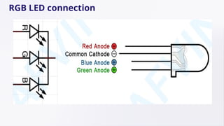
  • 16. Tricolor principle to display various colors PWM controlling ports to display full color Can be driven directly by Arduino PWM interfaces PWM (Pulse Width Modulation) is a technique used to control the power supplied to electronic components by rapidly switching the signal on and off. The duty cycle (ratio of on-time to off- time) determines the brightness of LEDs or the speed of motors. In Arduino, PWM is available on pins marked with a (~) symbol and is used with the analogWrite() function to create variable voltage levels for smooth dimming and color mixing in RGB LEDs. RGB LED
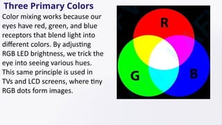
  • 17. Three Primary Colors Color mixing works because our eyes have red, green, and blue receptors that blend light into different colors. By adjusting RGB LED brightness, we trick the eye into seeing various hues. This same principle is used in TVs and LCD screens, where tiny RGB dots form images.
  • 20. Hardware Required • 1. Uno R3 Board *1 • 2.USB Cable *1 • 3.RGB LED *1 • 4.220Ω Resistor*3 • 5.Breadboard*1 • 6.Breadboard Jumper Wires* Several
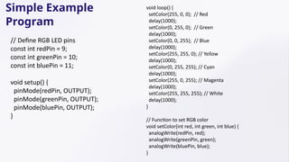
  • 22. // Define RGB LED pins const int redPin = 9; const int greenPin = 10; const int bluePin = 11; void setup() { pinMode(redPin, OUTPUT); pinMode(greenPin, OUTPUT); pinMode(bluePin, OUTPUT); } void loop() { setColor(255, 0, 0); // Red delay(1000); setColor(0, 255, 0); // Green delay(1000); setColor(0, 0, 255); // Blue delay(1000); setColor(255, 255, 0); // Yellow delay(1000); setColor(0, 255, 255); // Cyan delay(1000); setColor(255, 0, 255); // Magenta delay(1000); setColor(255, 255, 255); // White delay(1000); } // Function to set RGB color void setColor(int red, int green, int blue) { analogWrite(redPin, red); analogWrite(greenPin, green); analogWrite(bluePin, blue); } Simple Example Program
  • 23. Different Program // Define RGB LED pins int redpin = 11; // Red LED connected to pin 11 int bluepin = 10; // Blue LED connected to pin 10 int greenpin = 9; // Green LED connected to pin 9 int val; // Variable to store brightness values void setup() { // Set the RGB LED pins as outputs pinMode(redpin, OUTPUT); pinMode(bluepin, OUTPUT); pinMode(greenpin, OUTPUT); // Initialize serial communication at 9600 baud rate Serial.begin(9600); } void loop() { // Gradually decrease brightness from 255 to 0 for (val = 255; val > 0; val--) { analogWrite(11, val); // Adjust Red LED brightness analogWrite(10, 255 - val); // Adjust Blue LED brightness inversely analogWrite(9, 128 - val); // Adjust Green LED brightness delay(1); // Small delay for smooth fading } // Gradually increase brightness from 0 to 255 for (val = 0; val < 255; val++) { analogWrite(11, val); // Adjust Red LED brightness analogWrite(10, 255 - val); // Adjust Blue LED brightness inversely analogWrite(9, 128 - val); // Adjust Green LED brightness delay(1); // Small delay for smooth fading } // Print the current value of 'val' to the Serial Monitor Serial.println(val, DEC); }