Chap 8 The stack and introduction to procedures & Chapter 9 multiplication an...warda aziz
this pdf covers solution to chapter 8 and 9 of assembly language and organization of the IBM PC. if you find any mistakes in my writing , please disccuss with me.
chapter 7 Logic, shift and rotate instructionswarda aziz
this is a solution to exercise of chapter 7 from Assembly language programming and organization of the IBM PC.
If you find any mistakes in my solution , please discuss with me. as i am also a human and can do mistakes.
This document contains solutions to 12 questions related to assembly language programming and flow control instructions. The questions cover a range of topics including IF-THEN-ELSE logic, loops, arithmetic operations, character input/output, and string manipulation. Detailed assembly code solutions are provided for each question involving decision structures, loops, arithmetic sequences, reading/displaying characters, and finding the longest consecutive alphabetically increasing substring in a string.
assembly language programming organization of IBM PC chapter 9 part-1(MULTIPL...Bilal Amjad
This document contains presentation slides on bit shifting, multiplication, division, and their implementation in assembly language. It discusses:
- Using left and right bit shifts to perform multiplication and division by powers of 2
- The different instructions for signed vs unsigned multiplication and division (MUL, IMUL, DIV, IDIV)
- How multiplication and division results are stored in registers
- Examples of multiplying and dividing word and byte variables in assembly code
Binary and hex input/output (in 8086 assembuly langyage)Bilal Amjad
This document discusses binary and hexadecimal input/output algorithms. It contains pseudocode to convert character input into binary representations in a register and output binary values as characters. For binary input, each '0' or '1' character is converted and shifted left into a register. For hexadecimal input, characters are converted and shifted left by 4 bits into a register. To output, the register is rotated right and each 4-bit value is converted to a character.
Assembly Language Programming By Ytha Yu, Charles Marut Chap 10 ( Arrays and ...Bilal Amjad
This document discusses one-dimensional and two-dimensional arrays in assembly language. It covers topics such as:
- Declaring and initializing one-dimensional arrays
- Addressing individual elements using offsets from the base address
- Common addressing modes like register indirect, based, indexed, and based indexed to access array elements
- Storing two-dimensional arrays in row-major or column-major order and calculating element addresses
- Code examples to sum elements of a one-dimensional array and clear a row or column of a two-dimensional array
This document contains a solution manual for chapter 1 of a book on assembly language programming and the IBM PC. It provides answers to 10 multiple choice and short answer questions about computer memory, microprocessors, and assembly language concepts. The questions cover topics like memory addressing, data representation, components of the microprocessor like the EU and BIU, and advantages of high-level languages versus assembly languages.
Introduction to ibm pc assembly languagewarda aziz
The Solution manual of COAL
Chapter NO 4. exercise
if anyone has Questions Regarding this exercise.
contact me on my given Email-ID.
i will guide you. Thank you!
Chapter 5The proessor status and the FLAGS registerswarda aziz
solution manual to COMPUTER ORGANIZATION AND ASSEMBLY LANGUAGE CHAPTER 5.
If you find any mistake in the manual please share with me ... it will be appreciated
Assembly Language Programming By Ytha Yu, Charles Marut Chap 6 (Flow Control ...Bilal Amjad
The document discusses various high-level programming constructs like IF-THEN-ELSE, WHILE loops, FOR loops, and CASE statements and how they can be implemented using assembly language instructions. Conditional jumps, unconditional jumps, flags, and other instructions like LOOP, CMP, and JCXZ are used to emulate the flow control and conditional behavior of these high-level constructs. Examples are provided to demonstrate how to write assembly code equivalents for high-level statements like checking if a character is a capital letter, counting characters in a line, and displaying patterns based on conditions.
This document provides an outline for a course on 8086 Assembly Language Programming. It begins with an introduction to machine language and assembly language. It then covers topics like the organization of the 8086 processor, assembly language syntax, data representation, variables, instruction types, memory segmentation, program structure, addressing modes, and input/output. The document is intended to guide students through the key concepts needed to program in 8086 assembly language.
Organization of the ibm personal computerswarda aziz
The Solution manual of COAL
Chapter NO 3. exercise
if anyone has Questions Regarding this exercise.
contact me on my given Email-ID.
i will guide you. Thank you!
This presentation discusses logic and shift/rotate instructions in assembly language. It defines logic instructions like AND, OR, XOR and NOT and shows their truth tables. It explains how to use masks with these instructions to modify selective bits. It also covers shift/rotate instructions like SHL, SHR, ROL and ROR and how they manipulate bits by shifting them left or right in different ways. Examples are given to demonstrate how to use these instructions to clear, set or toggle bits using masks, as well as how shift/rotate instructions modify registers and flags.
Here are the steps:
1. MUL BL
- AL (85H) is multiplied by BL (35H)
- The 16-bit result (1B89H) is stored in AX, with the lower byte in AL and the higher byte in AH
So after the multiplication, AX = 1B89H.
Ex2: Assume that each instruction starts from these values:
DX:AX = 1234H, BX = 57H
1. DIV BX → Quotient in AX, Remainder in DX
This document discusses stacks and the push and pop instructions. It defines a stack as a LIFO (last in, first out) data structure. PUSH adds an item to the top of the stack, while POP removes an item from the top. Examples are given showing how data is added and removed from an empty stack using these instructions. The difference between PUSH and POP is explained, and stack register and how it is used to point to the current top of the stack is described.
The document summarizes information about flags registers in processors and flow control instructions in assembly language. It defines status and control flags that determine how the processor responds. It describes how jump, compare, and loop instructions can control program flow and provides examples of conditional jumps, unconditional jumps, IF-THEN structures, and WHILE, FOR, and REPEAT loops.
assembly language programming and organization of IBM PC" by YTHA YUEducation
This document contains solutions to chapters 1 through 10 of a manual on assembly language programming and organization of the IBM PC. It includes contents, chapter summaries, programming exercises and their solutions. Appendices provide information on how to run programs and some useful procedures.
The document discusses stacks, which are data structures that follow the LIFO (last in, first out) principle. It describes basic stack operations like push, pop, and peeking at the top element. Stacks can be implemented using arrays, vectors, or linked lists. In assembly language, the stack segment register SS and stack pointer SP are used to manage the call stack, temporarily storing return addresses and register values. PUSH adds an item to the top of the stack, while POP removes the top item.
Solution manual of assembly language programming and organization of the ibm ...Tayeen Ahmed
This introduction to the organization and programming of the 8086 family of microprocessors used in IBM microcomputers and compatibles is comprehensive and thorough. Includes coverage of I/O control, video/graphics control, text display, and OS/2. Strong pedagogy with numerous sample programs illustrates practical examples of structured programming.
Here are the key differences between CALL and INVOKE in x86 assembly:
- CALL is used to call a procedure without passing any parameters, while INVOKE allows passing parameters to procedures.
- When using CALL, any parameters need to be passed via registers or stack before the CALL. INVOKE handles pushing parameters onto the stack.
- A procedure called with CALL must pop its own parameters from the stack after the call, while a procedure called with INVOKE has the parameters automatically popped from the stack.
- INVOKE provides a simpler, higher-level way of calling procedures that mimics function calls in high-level languages by automatically handling parameter passing via the stack. CALL requires manually handling the
This document discusses different addressing modes used in computer architecture. It defines 10 addressing modes: immediate, register, register indirect, direct, indirect, implied, relative, indexed, base register, and autoincrement/autodecrement. Each addressing mode is described in terms of how the operand is specified and accessed from memory or registers. Examples are provided to illustrate each addressing mode.
This document discusses the flag register in the 8086 processor. It contains 9 flag bits that indicate the status of operations. The flags are classified as status flags (bits 0, 2, 4, 6, 7) or control flags (bits 8, 9, 10). It describes the purpose and meaning of each flag like the carry flag, parity flag, auxiliary flag, signed flag, zero flag, and overflow flags. It provides examples of how instructions can affect the different flag values.
In digital electronics, a decoder can take the form of a multiple-input, multiple-output logic circuit that converts coded inputs into coded outputs, where the input and output codes are different e.g. n-to-2n , binary-coded decimal decoders. Decoding is necessary in applications such as data multiplexing, 7 segment display and memory address decoding.
An encoder is a device, circuit, transducer, software program, algorithm or person that converts information from one format or code to another. The purpose of encoder is standardization, speed, secrecy, security, or saving space by shrinking size. Encoders are combinational logic circuits and they are exactly opposite of decoders. They accept one or more inputs and generate a multibit output code.
This document provides an overview of assembly language programming on the 8086 processor. It includes examples of assembly code using MOV, MUL, and other instructions. It then summarizes various 8086 instruction types like data transfer, arithmetic, logical, and control flow instructions. For each type, it lists some common instructions and provides brief descriptions and examples.
Linear data structures were discussed, specifically stacks. Stacks have applications such as reversing strings, balancing symbols, evaluating postfix expressions, and translating infix expressions to postfix. Reversing a string involves pushing characters onto a stack and then popping them off to output the reverse order. Balancing symbols uses a stack to check that every opening symbol has a closing match. Postfix expression evaluation pops operands from the stack and pushes results. Translating infix to postfix involves pushing operators onto a stack and outputting operands and popping higher priority operators.
This document contains information about converting regular expressions to finite automata. It discusses Kleene's theorem, which states that any language that can be defined by a regular expression can also be defined by a finite automaton and vice versa. It then provides steps for converting a regular expression to an NFA-Λ and converting an NFA-Λ to a finite automaton. The document concludes by recommending reviewing a textbook chapter on these topics.
Computer organization involves fetching instructions from memory and executing them. There are two main approaches to implementing the control unit: hardwired control and microprogrammed control. Hardwired control uses combinational logic to generate control signals based on the instruction and state, while microprogrammed control stores control sequences as microinstructions in a separate control store.
This document provides an introduction to a course on computer organization and assembly language. It will cover the main hardware components of a computer system, including memory, the CPU, and I/O ports. It will also discuss how instructions are executed in the fetch-execute cycle. Students will learn assembly language and how it maps to the underlying machine language understood by the CPU. They will be assessed through quizzes, assignments, a project, and a final exam.
The document discusses assembly language instruction addressing and execution. It covers loading an *.exe program by accessing it from disk and storing it in memory segments. The boot process and loading of an *.exe file is explained. Examples are provided to illustrate instruction execution and addressing, showing how the instruction address is determined from segment registers and offsets.
The document discusses applications of stacks, including reversing strings and lists, Polish notation for mathematical expressions, converting between infix, prefix and postfix notations, evaluating postfix and prefix expressions, recursion, and the Tower of Hanoi problem. Recursion involves defining a function in terms of itself, with a stopping condition. Stacks can be used to remove recursion by saving local variables at each step.
This document discusses stacks and their applications. It defines a stack as a Last In First Out (LIFO) data structure where newly added items are placed on top. The core stack operations of PUSH, POP, and PEEK are described. An array implementation of stacks is presented and animations demonstrate push and pop operations. Applications of stacks like checking for balanced braces, converting infix to postfix notation, and postfix calculators are explained with examples. Pseudocode provides an algorithm for infix to postfix conversion using a stack.
The document discusses stack and subroutines in assembly language programs. It explains that stack is used to store return addresses and save register contents. Subroutines allow breaking programs into modules and use CALL and RET instructions. An example program adds two numbers stored in memory locations and returns the result.
The document discusses different types of organization structures including functional, divisional, matrix, and emerging structures. It provides details on each structure type, describing their advantages and disadvantages. For example, it notes that a functional structure groups positions by specialized function which allows for expertise development but slow response to multi-function problems. A divisional structure groups positions by products/markets, enabling fast response to change but potential resource duplication.
This document outlines the basics of assembly language, including basic elements, statements, program data, variables, constants, instructions, translation to assembly language, and program structure. It discusses statement syntax, valid names, operation and operand fields. It also covers common instructions like MOV, ADD, SUB, INC, DEC, and NEG. Finally, it discusses program segments, memory models, and how to define the data, stack, and code segments.
The document provides an introduction to assembly language programming. It explains that assembly language uses mnemonics to represent machine instructions, making programs more readable compared to machine code. An assembler is needed to translate assembly code into executable object code. Assembly language provides direct access to hardware and can be faster than high-level languages, though it is more difficult to program and maintain.
This document discusses procedures, macros, and stack operations in assembly language. It explains that procedures allow repetitive code to be written once and called multiple times to save memory. Procedures use stack operations to push return addresses and data onto the stack. Macros simplify programming by reducing repetitive code. Procedures are called at runtime, while macro calls are replaced with their body at assembly time.
The document discusses the stack and calling subroutines in microcontrollers. It explains that when a CALL instruction is executed, the next instruction address (nPC) is pushed onto the stack. When a RETURN instruction is reached, nPC is popped from the stack to return to the calling instruction. The microcontroller uses a dedicated stack pointer register (SP) to keep track of the current stack location. Pushing increments SP, popping decrements SP. Examples are provided to demonstrate using CALL and RETURN to structure a program with subroutines. The document also briefly discusses pipelining instructions to improve processor efficiency.
This document discusses procedures in assembly language. It covers defining procedures, calling procedures using the CALL and RET instructions, passing parameters to procedures, and managing the runtime stack. Procedures use stack frames to access parameters passed on the stack and allocate space for local variables. Examples are provided of procedures that pass arguments by value and by reference.
A microprocessor is an electronic component that is used by a computer to do its work. It is a central processing unit on a single integrated circuit chip containing millions of very small components including transistors, resistors, and diodes that work together.
The document provides information about the instruction sets of the 8086 microprocessor. It defines what an instruction set is and describes the different instruction formats used by the 8086. The main types of 8086 instructions are then outlined, including data transfer instructions, arithmetic instructions, bit manipulation instructions, branch instructions, and others. Specific instructions like MOV, ADD, SUB, and MUL are explained through examples of their syntax and operation.
A stack is a data structure that follows the last-in, first-out (LIFO) principle. Elements can only be added or removed from one end, called the top. In computers, stacks are implemented using a portion of memory and the stack pointer register points to the top of the stack. When calling subroutines, the return address is saved on the stack using a push operation so the subroutine knows where to return to after executing. Parameters can be passed between the calling program and subroutine using registers or by pushing them onto the stack.
The document discusses the central processing unit (CPU) of a computer. It describes the three major parts of the CPU - the control unit, the arithmetic logic unit (ALU), and the register set. The control unit supervises operations and instructs the ALU. The register set stores intermediate data. The ALU performs arithmetic and logic operations to execute instructions. Memory units and instruction formats are also discussed.
This document provides an introduction to assembly language programming fundamentals. It discusses machine languages and low-level languages. It also covers data representation and numbering systems. Key assembly language concepts like instructions format, directives, procedures, macros and input/output are described. Examples are given to illustrate variables, assignment, conditional jumps, loops and other common programming elements in assembly language.
The stack is a group of memory locations used for temporary storage of data during program execution. Data is stored onto the stack in reverse order using PUSH instructions and retrieved using POP instructions. The stack pointer register (SP) points to the top of the stack. Subroutines use the stack to store the return address by pushing it onto the stack with a CALL instruction and popping it back into the program counter with a RET instruction. Conditional and restart CALL instructions transfer program flow based on flag settings or to fixed memory locations.
The document discusses assembly language programming concepts including the stack segment, stack, stack instructions, subroutines, macros, and recursive procedures. It provides examples and explanations of these concepts. It also includes sample programs and solutions related to stacks, subroutines, and other assembly language topics.
The document provides an overview of the 8085 microprocessor architecture and its assembly language programming. It discusses the 8085 block diagram, instruction set, sample assembly programs, use of counters and delays, stack and subroutines. It then introduces the 8086 and x86 architectures. The next class will cover the 8086 architecture in more detail, advanced 32-bit architectures, the x86 programming model, 8086 assembly language programming, and x86 assemblers.
The document discusses concepts related to instruction addressing and execution in computer architecture. It explains that programs are loaded into separate code, data, and stack segments in memory. When an *.exe file is loaded, it places the program after a 256-byte Program Segment Prefix on a paragraph boundary, and loads the segment registers with the starting addresses of code, data, and stack. It then provides examples of instruction fetching and decoding, showing how the segment and instruction pointers are used to determine memory addresses for instruction execution.
This document discusses procedures in assembly language. It covers defining procedures, documenting procedures, using the CALL and RET instructions to call and return from procedures, and examples of procedures including a SumOf procedure and nested procedure calls. Local variables within procedures are also mentioned.
IoT Based Smart Energy Meter using Raspberry Pi and Arduino Bilal Amjad
This project, design and implemented a low-cost IoT based energy monitoring system (smart energy meter) for real-time monitoring of all electrical parameters i.e. AC voltage, AC current, active power, total energy consumption, power factor, frequency, and tariff. The design is based on a low-cost PZEM-004T, using a non-invasive Current Transformer
(CT) sensors, Arduino and Raspberry pi. Electrical measurements are done by PZEM-004T and CT sensors through Arduino. Raspberry pi communicates with Arduino through serial communication to retrieve these sensor’s data and send it to the server via internet. As a result, the developed energy monitoring system can successfully record the voltage, current, active power, power factor, frequency, accumulative power consumption and tariff. Consumers will be able to
see their electricity usage and the tariff according to the energy usage in real-time through web and mobile application. In case of any fault e.g., short circuit or power supply cut off, the consumer will receive a text message on his mobile number. Moreover, consumers will be able to receive the tariff on a weekly or monthly basis.
Power Systems analysis with MATPOWER and Simscape Electrical (MATLAB/Simulink) Bilal Amjad
The report analyses the power flow studies done in MATPOWER, some three-phase circuits and the operation of the DFIG wind turbine using Simcape Electrical library in Simulink.
The work was submitted to the University of Bradford as a part of the coursework during my MSc program.
Solar Radiation monthly prediction and forecasting using Machine Learning tec...Bilal Amjad
The whole world is trying to reduce the CO2 emission by using renewable energy resources
(RERs) instead of fossil fuels especially for electricity generation. One of the main RERs for
electricity is the sun. Soler panels are used are used for capturing the energy of the sun using photovoltaic
(PV) cells. The output of PV’s depends on the weather and climate.
So, it is very important to know how much energy can be harvested in upcoming years or months
by predicting the solar energy for a particular area of earth, using historical data. In this work, two
machine learning techniques are used to forecast solar radiation using historical data. This will
help the energy companies in planning and designing of long-term goals for sustainable electricity
generation.
A presentation on "Big Data in Smart Grid" by MSc students at the University of Bradford, submitted as a part of coursework. It addresses the challenges, opportunities and issues related to Big Data and Data Protection in Smart Grid.
Flexibility of Power System (Sources of flexibility & flexibility markets)Bilal Amjad
This presentation gives a detail explanation of power system flexibility, flexibility in traditional power system, future flexibility needs and resources and flexibility markets.
Assembly Language Programming By Ytha Yu, Charles Marut Chap 1(Microcomputer ...Bilal Amjad
This document discusses computer languages and microprocessor-based systems. It describes how machine language uses binary instructions to directly control a processor's circuitry. Assembly language and high-level languages were developed to bridge the gap between machine language and what is convenient for humans. Assembly language uses symbolic names for operations and memory locations and converts to machine language via an assembler. High-level languages like Pascal and COBOL use expressions and symbols from English and convert to machine language via a compiler. Advantages of assembly language include better performance and access to hardware for some applications where speed and size are critical.
bubble sorting of an array in 8086 assembly languageBilal Amjad
The document describes bubble sort algorithm and includes code to implement it in assembly language. It lists group members and provides examples of bubble sort on sample data. It also includes pseudo code of the bubble sort procedure that sets the offset address and array size as inputs, sorts the array in ascending order, and returns the sorted array as output. The code segment implements bubble sort by getting input from the user, calling the bubble sort procedure to sort it, and displaying the sorted output.
assembly language programming organization of IBM PC chapter 9 part-2(decimal...Bilal Amjad
This document contains source code for decimal input and output in assembly language. It discusses algorithms for converting decimal numbers to binary representations for input, and binary representations back to decimal for output. The input algorithm reads characters, converts them to digits, and multiplies a running total by 10 before adding the digit value. The output algorithm divides the number by 10 repeatedly to extract digits, converts them to characters, and prints them to display the number in decimal form.
The document lists the group members working on limits of complex functions. It then provides two definitions of limits - the first conceptual definition, and the second more precise "epsilon-delta" definition introduced by Bernard Bolzano in 1817. It explains that the epsilon refers to how close the function value needs to be to the limit, while delta refers to how close the input needs to be to still satisfy the epsilon condition. Some examples are then worked out to demonstrate the limit concept. Applications of limits in various engineering and science fields are discussed, such as fluid mechanics, mechanical design, astronomy, business, and medicine. It concludes by noting that what qualifies as "close enough" can depend on the context and precision needed.
This document describes a simple combination lock circuit that uses XOR gates to compare a 4-bit entered code to a stored key code. If the bits match, a green "Go" LED lights up, and if they do not match, a red "No Go" LED lights up. The circuit includes XOR gates, NOR gates, switches to enter the code, LEDs, resistors, and a pushbutton to submit the code for comparison.
The document describes a 4-bit comparator circuit that compares two 4-bit binary numbers and outputs whether they are equal, if the first number is less than the second, or if the first is greater. It provides examples of the circuit comparing different 4-bit inputs and correctly outputting the relationship between the numbers. The comparator circuit has applications in electronic locks and security devices to compare binary passwords.
This document discusses orthogonal trajectories and provides examples of finding orthogonal trajectories for different families of curves. It begins by defining orthogonal trajectories as curves that intersect each other at right angles. It then provides a method for finding the differential equation that describes the orthogonal trajectories for a given family of curves. Several examples are worked out, such as finding the orthogonal trajectories of the family of parabolas with equation y = x^2. Applications to equipotential lines and electric fields and electromagnetic waves are also mentioned.
ELectronics Boards & Product Testing_Shiju.pdfShiju Jacob
This presentation provides a high level insight about DFT analysis and test coverage calculation, finalizing test strategy, and types of tests at different levels of the product.
The role of the lexical analyzer
Specification of tokens
Finite state machines
From a regular expressions to an NFA
Convert NFA to DFA
Transforming grammars and regular expressions
Transforming automata to grammars
Language for specifying lexical analyzers
Lidar for Autonomous Driving, LiDAR Mapping for Driverless Cars.pptxRishavKumar530754
LiDAR-Based System for Autonomous Cars
Autonomous Driving with LiDAR Tech
LiDAR Integration in Self-Driving Cars
Self-Driving Vehicles Using LiDAR
LiDAR Mapping for Driverless Cars
Analysis of reinforced concrete deep beam is based on simplified approximate method due to the complexity of the exact analysis. The complexity is due to a number of parameters affecting its response. To evaluate some of this parameters, finite element study of the structural behavior of the reinforced self-compacting concrete deep beam was carried out using Abaqus finite element modeling tool. The model was validated against experimental data from the literature. The parametric effects of varied concrete compressive strength, vertical web reinforcement ratio and horizontal web reinforcement ratio on the beam were tested on eight (8) different specimens under four points loads. The results of the validation work showed good agreement with the experimental studies. The parametric study revealed that the concrete compressive strength most significantly influenced the specimens’ response with the average of 41.1% and 49 % increment in the diagonal cracking and ultimate load respectively due to doubling of concrete compressive strength. Although the increase in horizontal web reinforcement ratio from 0.31 % to 0.63 % lead to average of 6.24 % increment on the diagonal cracking load, it does not influence the ultimate strength and the load-deflection response of the beams. Similar variation in vertical web reinforcement ratio leads to an average of 2.4 % and 15 % increment in cracking and ultimate load respectively with no appreciable effect on the load-deflection response.
We introduce the Gaussian process (GP) modeling module developed within the UQLab software framework. The novel design of the GP-module aims at providing seamless integration of GP modeling into any uncertainty quantification workflow, as well as a standalone surrogate modeling tool. We first briefly present the key mathematical tools on the basis of GP modeling (a.k.a. Kriging), as well as the associated theoretical and computational framework. We then provide an extensive overview of the available features of the software and demonstrate its flexibility and user-friendliness. Finally, we showcase the usage and the performance of the software on several applications borrowed from different fields of engineering. These include a basic surrogate of a well-known analytical benchmark function; a hierarchical Kriging example applied to wind turbine aero-servo-elastic simulations and a more complex geotechnical example that requires a non-stationary, user-defined correlation function. The GP-module, like the rest of the scientific code that is shipped with UQLab, is open source (BSD license).
Sorting Order and Stability in Sorting.
Concept of Internal and External Sorting.
Bubble Sort,
Insertion Sort,
Selection Sort,
Quick Sort and
Merge Sort,
Radix Sort, and
Shell Sort,
External Sorting, Time complexity analysis of Sorting Algorithms.
How to use nRF24L01 module with ArduinoCircuitDigest
Learn how to wirelessly transmit sensor data using nRF24L01 and Arduino Uno. A simple project demonstrating real-time communication with DHT11 and OLED display.
Data Structures_Linear data structures Linked Lists.pptxRushaliDeshmukh2
Concept of Linear Data Structures, Array as an ADT, Merging of two arrays, Storage
Representation, Linear list – singly linked list implementation, insertion, deletion and searching operations on linear list, circularly linked lists- Operations for Circularly linked lists, doubly linked
list implementation, insertion, deletion and searching operations, applications of linked lists.
its all about Artificial Intelligence(Ai) and Machine Learning and not on advanced level you can study before the exam or can check for some information on Ai for project
3. The Stack
• The stack segment of a program is used for temporary
storage of data and addresses
• A stack is a one-dimensional data structure
• Items are added to and removed from one end of the
structure using a "Last In - First Out" technique (LIFO)
• The top of the stack is the last addition to the stack
• The statement .STACK 100H in your program sets
aside a block of 256 bytes of memory to hold the stack
• The SS (Stack Segment Register) contains the segment
number of the stack segment
4. The Stack (cont’d)
• The complete segment:offset address to access the stack
is SS:SP
• Initially before any data or addresses have been placed on
the stack, the SP contains the offset address of the
memory location immediately following the stack segment
6. PUSH Instruction
• PUSH instruction adds a new word to the stack
• SYNTAX: PUSH source
where source is a 16-bit register or memory
word
• PUSH instruction causes
– the stack pointer (SP) to be decreased by 2.
– Then a copy of the value in the source field is placed in
the address specified by SS:SP.
7. • Initially SP points to a location immediately
following the stack. The first push decreases
SP by 2, making it point to the last word in the
stack
• Because each PUSH decreases the SP, the
stack is filled a word at a time backwards from
the last available word in the stack toward the
beginning of the stack.
8. How Words Are Added To Stack
Offset
0000
00F4
00F6
00F8
00FA
00FC
00FE
0100
It stack is empty, SP has a value of
100h; otherwise it has a value
between 0000-00FEh
SP:
(Beyond the end of the stack)
SP
9. How Words Are Added To Stack
Offset
0000
00F4
00F6
00F8
00FA
00FC
00FE
0100
0100SP:
(Beyond the end of the stack)
SP
1234AX:
5678BX:
10. How Words Are Added To Stack
Offset
0000
00F4
00F6
00F8
00FA
00FC
00FE
0100
00FESP:
(Beyond the end of the stack)
SP
1234AX:
5678BX:
1234
11. How Words Are Added To Stack
Offset
0000
00F4
00F6
00F8
00FA
00FC
00FE
0100
(Beyond the end of the stack)
SP
1234AX:
5678BX: 5678
1234
00FCSP:
12. POP Instruction
• POP instruction removes the last word placed on the stack
• SYNTAX: POP destination
– where source is a 16-bit register or memory word
• POP instruction causes
– the contents of SS:SP to be moved to the destination field
– It increases the stack pointer (SP) by 2
• Restrictions:
1.PUSH and POP work only with words
2.Byte and immediate data operands are illegal
13. How Words Are Added To Stack
Offset
0000
00F4
00F6
00F8
00FA
00FC
00FE
0100
(Beyond the end of the stack)
SP
FFFFCX:
0001DX:
5678
1234
00FCSP:
14. How Words Are Added To Stack
Offset
0000
00F4
00F6
00F8
00FA
00FC
00FE
0100
(Beyond the end of the stack)
SP
FFFFCX:
0001DX:
5678
1234
00FESP:
5678
15. How Words Are Added To Stack
Offset
0000
00F4
00F6
00F8
00FA
00FC
00FE
0100
(Beyond the end of the stack)
SP
FFFFCX:
0001DX:
5678
1234
0100SP:
5678
1234
16. FLAGS Register and Stack
• PUSHF
– pushes (copies) the contents of the FLAGS register onto
the stack. It has no operands
• POPF
– pops (copies) the contents of the top word in the stack to
the FLAGS register. It has no operands
• NOTES:
– PUSH, POP, and PUSHF do not affect the flags !!
– POPF could theoretically change all the flags because it resets the
FLAGS REGISTER to some original value that you have previously saved
with the PUSHF instruction
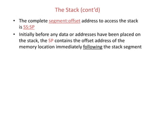
17. Example: Fill up the trace table given below.
Instructions AX
MOV AX,843AH
BX CX SI SP Stack Data Address Data
0100
0101
0102
0103
0104
0105
0106
0107
0108
0109
010A
010B
010C
010D
010E
3F
78
5A
C8
93
59
4F
A3
7E
F4
09
8A
5C
6A
45
INC AX
PUSH AX
MOV BX, 2354H
MOV BL,AL
POP AX
PUSH BX
MOV SI,0104H
PUSH [010A]
POP DX
POP AX
PUSH [SI+4]
INC AL
POP AX
INC AX
19. Important Notes
• Not only can the programmer use the stack but DOS can
and also does use the stack
• In fact DOS uses the stack every time the user executes an
INT 21h function
• Because of the "last-in first-out" nature of the stack, the
order that items are removed from the stack is the reverse
of the order in which they are placed on the stack
20. Example Program
• The following code allows a user to input a string
consisting of 10 characters and then displays the 10
characters in reverse order on the screen
TITLE DISPLAY THE 10 CHARACTERS IN REVERSE ORDER
.MODEL SMALL
.STACK 100H
.DATA
CR EQU 0DH
LF EQU 0AH
MESSAGE DB CR,LF,'PLEASE TYPE ANY 10 '
DB ' CHARACTERS',CR,LF,'$'
REVERSE DB CR,LF,'THE CHARACTERS IN REVERSE'
DB ' ARE:',CR,LF,'$'
22. READ:
INT 21H
PUSH AX ;CAN'T PUSH AL SO PUSH AX!
LOOP READ
;-----------------------------PRINT REVERSE MESSAGE
MOV AH,9
LEA DX,REVERSE
INT 21H
;-----------------------------PREPARE TO PRINT IN REVERSE
MOV CX,10
MOV AH,2
Example
Program
(cont’d)
23. DISP:
POP DX
INT 21H
LOOP DISP
;-----------------------------RETURN TO DOS
MOV DL,CR
INT 21h
MOV DL,LF
INT 21h
MOV AH,4CH
INT 21H
MAIN ENDP
END MAIN
Example
Program
(cont’d)
24. Terminology of Procedures
• Top-down program design
– Decompose the original problem into a series of
subproblems that are easier to solve than the original
problem
• Subproblems in assembler language can be structured as a
collection of procedures
• Main procedure contains the entry point to the program
and can call one of the other procedures using a CALL
statement
• It is possible for a called sub-procedure to call other
procedures
• In AL, it is also possible for a called sub-procedure to call
itself (recursion)!
25. Terminology of Procedures (cont’d)
• When a procedure calls another procedure,
control transfers to the called procedure
• When the instructions in a called procedure
have been executed, the called procedure
usually returns control to the calling
procedure at the next sequential
instruction after the CALL statement
• In high level languages, mechanism for call
and return are hidden from programmer
26. Procedure Declaration
name PROC type
; body of procedure
RET
name ENDP
User defined
name
Optional
operand
Near
Statement calls
the procedure in
the same segment
Far
Statement calls the
procedure in the
different segment
Causes the
control to
transfer back to
the calling
procedure
Every procedure should
have a RET coded
somewhere within the
procedure - usually the last
instruction in a procedure
27. PROC Instruction
• PROC instruction establishes a procedure
• Procedure declaration syntax:
name PROC
; body of the procedure
RET
name ENDP
• name is a user-defined variable.
• RET instruction causes control to transfer back to
the calling Procedure.
• Every procedure should have a RET coded
somewhere within the procedure - usually the last
instruction in a procedure
Main PROC
CALL PROC1
next instruction
PROC1 PROC
next instruction
RET
28. Before Call
Main PROC
CALL PROC1
next instruction
0010
0012
PROC1 PROC
next instruction
RET
0020
00FE
0100
00FC
29. COMMUNICATION BETWEEN PROCEDURES
• Programmers must devise a way to
communicate between procedures –
• there are no parameter lists !!!
• Typically in assembler language, procedures
often pass data to each other through
registers
30. Procedures Documentation
• Procedures should be well-documented
– Describe what the procedure does
– Indicate how it receives its input from the calling program
– Indicate how it delivers the results to the calling program
– Indicate the names of any other procedures that this procedure
calls
; Describe what the procedure does
; input: Indicate how it receives its input
from the calling program
; output: Indicate how it delivers the results
to the calling program
; uses: Indicate the names of any other
procedures that this procedure calls
31. Procedures (cont’d)
• A procedure usually begins by PUSHing (saving) the
current contents of all of the registers on the stack.
• A procedure usually ends by POPing the stack contents
back into the registers before returning to the CALLing
procedure
• When writing a procedure, do NOT PUSH or POP any
registers in which you intend to return output!!
32. CALL Instruction
• A CALL instruction invokes a procedure
• SYNTAX: CALL name (direct CALL)
where name is the name of a procedure.
• Executing a CALL instruction causes the following to happen:
– The return address of the CALLing program which is in the IP register is
pushed (saved) on the STACK. This saved address is the offset of the
next sequential instruction after the CALL statement (CS:IP)
– The IP then gets the offset address of the first instruction in the
procedure
33. RET Instruction
• RET statement cause the stack to be popped into IP.
Procedures typically end with a RET statement.
• Syntax: RET
• Once the RET is executed, CS:IP now contains the
segment offset of the return address and control returns
to the calling program
• In order for the return address to be accessible, each
procedure must ensure that the return address is at the
top of the stack when the RET instruction is executed.
34. Before Call
Main PROC
CALL PROC1
next instruction
0010
0012
PROC1 PROC
next instruction
RET
0020
00FE
0100
00FC
35. AFTER Call
Main PROC
CALL PROC1
next instruction
0010
0012
PROC1 PROC
next instruction
RET
0020
00FE
0100
00FC
36. Before RET
Main PROC
CALL PROC1
next instruction
0010
0012
PROC1 PROC
next instruction
RET
0020
00FE
0100
00FC
0030
37. After RET
Main PROC
CALL PROC1
next instruction
0010
0012
PROC1 PROC
next instruction
RET
0020
00FE
0100
00FC
0030
38. Typical Layout of a Program Containing
Procedures
TITLE A PROGRAM THAT CONTAINS SEVERAL PROCEDURES
.MODEL SMALL
.STACK 100H
.DATA
;*** define data elements here *******
.CODE
MAIN PROC
; INITIALIZE DATA SEGMENT REGISTER
MOV AX,@DATA
MOV DS,AX
;*** code any necessary statements here ***
;*** get ready to call procedure ABC by ***
;*** first moving input values to appropriate registers ***
CALL ABC
39. Typical Layout (cont’d)
;*** code any necessary statements here ***
;*** get ready to call procedure DEF by ***
;*** first moving input values to appropriate registers ***
CALL DEF
;*** code any necessary statements here ***
;*** get ready to call procedure GHI by ***
;*** first moving input values to appropriate registers ***
CALL GHI
;*** code any necessary statements here ***
; RETURN TO DOS
MOV AH,4CH
INT 21H
MAIN ENDP
40. Typical Layout (cont’d)
ABC PROC
PUSH ..... ; as many PUSHes as you need
POP ..... ; POPs in reverse order of PUSHes
RET
ABC ENDP
;
DEF PROC
PUSH ..... ; as many PUSHes as you need
POP ..... ; POPs in reverse order of PUSHes
RET
DEF ENDP
;
41. Typical Layout (cont’d)
GHI PROC
PUSH ..... ; as many PUSHes as you need
POP ..... ; POPs in reverse order of PUSHes
RET
GHI ENDP
END MAIN
42. Example Program
• Now let’s study the Multiplication Procedure
Product = 0
Repeat
IF lsb of B is 1
then
product = product + A
end_if
shift left A
shift right B
Until B = 0
43. Example Program (cont’d)
TITLE MULTIPLICATION BY ADDING AND SHIFTING (8 BITS BY 8 BITS)
.MODEL SMALL
.STACK 100H
.CODE
MAIN PROC
;------------------------------> INITIALIZE AX AND BX
MOV AX,13 ;SOME ARBITRARY VALUE
MOV BX,10 ;SOME ARBITRARY VALUE
;------------------------------> INVOKE PROCEDURE
CALL MULTIPLY
;------------------------------> DX NOW CONTAINS PRODUCT
; RETURN TO DOS
MOV AH,4CH
INT 21H
MAIN ENDP
44. Example (cont’d)
MULTIPLY PROC
;-----------------------------> THIS PROCEDURE MULTIPLIES THE
;-----------------------------> VALUE IN AX BY THE VALUE IN BX
;-----------------------------> RETURNING THE PRODUCT IN DX.
;-----------------------------> VALUES IN AX AND BX ARE LIMITED ;-----------------------------> TO 00 - FFh.
;-----------------------------> IT USES SHIFTING AND ADDITION
;-----------------------------> TO ACCOMPLISH THE MULTIPLICATION
PUSH AX ; DON'T DESTROY AX
PUSH BX ; DON'T DESTROY BX
XOR DX,DX ; CLEAR DX WHERE PRODUCT WILL BE
REPEAT:
TEST BX,1 ; IS LSB = 0?
JZ END_IF
ADD DX,AX ; PRODUCT = PRODUCT + A
END_IF:
SHL AX,1
SHR BX,1
JNZ REPEAT
POP BX
POP AX
RET
MULTIPLY ENDP
END MAIN
45. Important Notes on Stack
• PUSHES AND POPS are often used to save data temporarily on the
program stack. They are also used implicitly each time a CALL and a
RETurn sequence is executed.
• Remember that the SP is decremented BEFORE placing a word on the
stack at PUSH time but it is incremented AFTER removing a word from
the stack at POP time.
• If, for some reason, you want a copy of the FLAGS register in BX, you
can accomplish this by:
PUSHF
POP BX
• Stack allows you to save the contents of a register, use the register for
something else temporarily, and the restore the register to its original
value.
46. Notes on Stack (cont’d)
• Pushing and popping the contents of registers is preferable to storing
their contents as variables in the DATA segment
• Reasons:
– Using the stack is more economical. Instead of allocating data space, by
pushing and popping data into the stack, you use space as you need it
and release it when you no longer need it.
– Since the 8088/8086 allows recursion, if a routine called itself and saved
the contents of a register to a data location each time it was invoked, it
would be overwriting the previous contents of that location with each
recursion!
– Using a stack instead of a data location makes code more portable. Once
you have written a good routine, you may choose to incorporate that
routine into several different programs. Or if you are working with a
programming team piecing smaller subroutines into a one larger main
routine, subroutines that do their work without referencing particular
data locations are more easily patched into main programs than
subroutines that do reference particular data locations. Therefore, should
not refer to ANY variable data names in ANY procedure that you write!!!'
47. Notes on Stack (cont’d)
• Care must be taken not to corrupt the STACK because not only does it
save values for the programmer but it also saves values for the CPU.
These values get interwoven on the stack. If the SP becomes
confused, the CPU could get lost throwing your computer into a
system error!!
• Always check to see that the PUSHES and POPS in a program are
paired --- or --- at least that each of them is balanced by program
code that restores the stack pointer to its proper value.
• If you find yourself in the middle of a system error, more than likely
you look for a problem in the way you implemented the stack.
48. Example Procedure on Safe Use of Stack
• A procedure to display a carriage return and a line feed:
CRLF PROC
PUSH AX ; Save AX
PUSH DX ; Save DX
MOV AH,2 ; Display a Carriage Return
MOV DL,0Dh
INT 21h
MOV DL,0Ah ; Display a Line Feed
INT 21h
POP DX ; Restore DX
POP AX ; Restore AX
RET
CRLF ENDP
49. Example (cont’d)
• This procedure can be called by the programmer at any time regardless of
what is in his/her AX or DX registers. As far as the programmer is
concerned, all you know is that this procedure issues the CR/LF sequence
to the console and all of your registers will be unchanged when the
procedure has finished executing!