


![1 Introduction
40
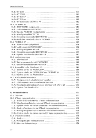
Fig. 1.18 Structure of the project data for a PLC station
< PLC_xxx >
Program blocks
Watch and force tables
PLC data types
Local modules
Technology objects
System blocks
External source files
PLC tags
< Group_1 >
< Group_1 >
< Group_1 >
< Technology object_1 >
Device configuration
Add new block
Add new watch table
Add new data type
< PLC data type_1 >
Add new object
Add new external file
< External program source >
Show all tags
Add new tag table
Default tag table [n]
< Tag table [n] >
Online & diagnostics
Main [OB1]
< Watch table_2>
< Block_2 >
<Tag table_1 [n]>
< Block_1 >
< Watch table_1 >
Force table
Text lists
PLC messages
Program info
Traces
Starts the editor for device configuration
Creates a new block and opens it
Creates a new watch table and opens it
Adds a new PLC data type
Self-created PLC data type
Self-created watch table
Table with the force tags
Station-specific texts for user and system messages
PLC, user diagnostics and system messages
Shows program structure, assignment list, CPU resources
Editor for recording and displaying measured value series
Self-created block
Creates a new technology object and opens it
Imports a program source
Imported program source
Shows all PLC tags of all tables
Adds a new tag table
Automatically created tag table with n tags
Self-created tag table with n tags
Starts the editor for the online connection and diagnostics
Self-created groups with more watch tables can be used under
for structuring.
Watch and force tables
Folder for all data of a PLC station (name can be freely selected)
Folder for all blocks of the user program
Folder for all watch and force tables
Folder for all PLC data types
Folder for the local modules of the PLC station
Folder for all technology objects
Folder for the system blocks used
Folder for the program sources
Folder for all PLC tags
Under , further blocks can be created in addition
to the permanently existing block (main program).
The block collection can be structured using self-created groups
which contain further blocks.
Program blocks
Main [OB1]
Self-created groups with further tag (partial) tables can be used
under for structuring.
PLC tags
Self-created technology object
Data structure of a PLC station](https://image.slidesharecdn.com/33864-250411160233-872682cf/85/Automating-with-SIMATIC-S7-300-inside-TIA-Portal-Configuring-Programming-and-Testing-with-STEP-7-Professional-2nd-Edition-Hans-Berger-45-320.jpg)


![(c) The nerves passing through the sphenoidal fissure.
proportion of cases, more especially those in which there is a
peripheral concentric loss of vision, the more central fibres escaping.
It is possible, also, that cases evidencing temporal or nasal blindness
may be due, as J. J. Evans[17] thinks, to a contre-coup contusion of
the nerve through it being forcibly driven against the bony
boundaries of the foramen. Taking into consideration, however, the
very frequent presence of a fracture through the anterior clinoid
process (see p. 82), and the usual displacement of that process, it
would appear probable that immediate and more or less complete
loss of vision results from the compression and crushing of the optic
nerve by reason of the pressure exercised by a displaced clinoid
process.
The following statistics add confirmation to this view. Thus,
Callen collected 17 cases in which the optic nerve was compressed
by osseous fragments in the region of the optic foramen, whilst
Holder observed injury to the bones entering into the formation of
the foramen in 53 out of 86 cases of fracture involving this region.
The prognosis varies according to the cause of the blindness.
When resulting from concussion of the nerve trunk or from
hæmorrhage into its sheath, certain fibres may regain their function.
In the majority of cases, however, that have come under my own
observation, blindness of the affected eye was immediate and
permanent.
The
ophthalmic division of the fifth nerve is rarely injured to such a
degree as to cause anæsthesia of all the regions supplied. Blood
extravasation into the surrounding regions, or direct involvement of
one of the branches of the nerve, often results in areas of
anæsthesia, and some few cases have been recorded in which there
was complete anæsthesia of both cornea and conjunctiva, with
subsequent ulceration and sloughing. The nasal nerve may be
implicated as the result of a fracture involving the cribriform plate,
whilst the supra-orbital and supra-trochlear branches may be
damaged by fractures of the vertical plate of the frontal bone.
The third nerve is similarly liable to injury, in any part of its
orbital course. It is quite exceptional, however, for the whole trunk](https://image.slidesharecdn.com/33864-250411160233-872682cf/85/Automating-with-SIMATIC-S7-300-inside-TIA-Portal-Configuring-Programming-and-Testing-with-STEP-7-Professional-2nd-Edition-Hans-Berger-57-320.jpg)


![ears, from the numerous tympanic vessels, from the lateral sinus,
and from the middle meningeal artery. The amount of blood which
escapes varies according to the source of the hæmorrhage. When
hæmorrhage occurs from the smaller vessels, the blood either clots
in the external meatus or trickles from the ear. In the most severe
cases the hæmorrhage is profuse and long-continued. Some years
ago a case came under my observation that threw light on the
probable source of such severe hæmorrhages.
A man was admitted into the hospital, suffering from profuse hæmorrhage
from the ear as the result of a fall down an area. The bleeding continued for
fourteen hours, soaking the dressings and continuing so long as the man lived. At
the post-mortem examination an extensive comminution of the tegmen tympani
was discovered, the fracture being associated with great extra-dural extravasation
of blood from a lacerated middle meningeal artery. The extra-dural hæmorrhage
was enabled to escape through the tegmen tympani into the middle ear, and
thence by means of the lacerated membrana tympani (see Fig. 38).
Profuse and long-continued hæmorrhage from the ear should
always arouse suspicion as to the possibility of injury to the middle
meningeal artery. Since meeting the case recounted above, many
similar cases have come under my care, and, in several instances,
guided by this symptom alone, operative measures have been
carried out successfully.
The two following cases show, however, that the extra-dural
extravasation may be derived not only from the middle meningeal
artery but also from the lateral sinus.
‘A man fell down an area and suffered from continuous hæmorrhage from the
ear. He remained in bed for a few days, and then, becoming tired of confinement,
got up, walked some distance on a cold and frosty day, and visited a sage femme.
On returning home he complained of feeling ill, the hæmorrhage from the ear
ceased, and shortly afterwards he became unconscious and died. The autopsy
showed an extensive fracture of the petrous bone with extensive extra-dural
hæmorrhage from a torn lateral sinus and from a lacerated meningeal artery.’[18]
The man had remained fairly well so long as the extra-dural blood was
permitted a free means of escape through the tegmen tympani and external
auditory meatus, but, so soon as clotting occurred, compression symptoms
developed and the man died in that condition.](https://image.slidesharecdn.com/33864-250411160233-872682cf/85/Automating-with-SIMATIC-S7-300-inside-TIA-Portal-Configuring-Programming-and-Testing-with-STEP-7-Professional-2nd-Edition-Hans-Berger-60-320.jpg)
![Special points in prognosis and treatment.
‘A man, 50 years of age, fell down, striking his head against the kerb. On
admission it was seen that blood was trickling freely through a torn membrana
tympani. He rapidly became unconscious and died. The post-mortem examination
revealed a fracture involving the middle ear and external auditory meatus, passing
backwards across the lateral sinus, in which region there was a large extra-dural
extravasation of blood.’[19]
The above statements are confirmed by Dwight,[20] who, in 146
autopsies, found that, in 69 per cent. cases of fracture of the middle
fossa of the skull, there was bleeding from the ear, and that in 29
per cent. cases the fracture was associated with laceration of
branches of the middle meningeal artery.
Although hæmorrhage from the external auditory meatus may
be regarded as almost diagnostic of a middle fossa fracture,
especially of that variety previously described as the ‘typical basic
fracture’, yet the blood may be derived from a torn membrana
tympani or from laceration of the lining cuticle of the external
meatus. Aural examination will soon prove whether the blood is
coming through a rent in the membrane, in which case the diagnosis
is clear. Sometimes bleeding takes place from both ears, a symptom
practically diagnostic of the transverse middle fossa fracture known
as the ‘typical basic fracture’.
The following statistics will supply further information as to the
relative frequency with which hæmorrhage occurs from ears, nose,
and mouth, and the proportionate mortality. The cases were
collected and tabulated by Crandon and Wilson.
Cases. Lived. Died. Mortality.
Hæmorrhage from the ear 281 170 111 39 per cent.
Hæmorrhage from both ears 47 16 31 66 per cent.
Hæmorrhage from the nose 44 17 27 61 per cent.
Hæmorrhage from the mouth 168 73 93 33 per cent.
It is not possible to
formulate any very definite prognosis when the hæmorrhage takes
place from one ear only, though the mortality is about 40 per cent.
When bleeding takes place from both ears the outlook is more
grave, the mortality being about 66 per cent.](https://image.slidesharecdn.com/33864-250411160233-872682cf/85/Automating-with-SIMATIC-S7-300-inside-TIA-Portal-Configuring-Programming-and-Testing-with-STEP-7-Professional-2nd-Edition-Hans-Berger-61-320.jpg)


![The twelfth nerve.
posterior fossa of the skull towards the outer angle of the jugular
foramen and cutting across the petrous bone (see p. 104).
The ninth, tenth, and eleventh cranial nerves may be injured in
the same variety of fracture. These three nerves are, however, so
protected by their dural sheaths that they generally escape injury.[21]
In the following cases the nerves were involved:—
The patient was admitted suffering from a fracture resulting from a blow on
the posterior parietal region. During the next four days no special symptoms
developed. On the fifth day, during a sudden attack of dyspnœa and dysphagia,
death occurred. A fissured fracture was found which extended into the jugular
foramen, a region occupied by blood-clot.
A man committed suicide by means of a pistol-bullet fired through the mouth.
The bullet lodged against the under surface of the petrous bone, tearing the
jugular vein and lacerating the nerves passing through that foramen.
In another case the patient was admitted with a fractured base. He
progressed favourably until the tenth day when, on sitting up suddenly in bed, he
was seized with rigors, dyspnœa, and dysphagia, dying shortly afterwards. A basic
fracture was found, practically dividing the skull into two parts and involving the
jugular foramen. Displacement had occurred with consequent compression of the
ninth, tenth, and eleventh nerves.
The anterior condyloid foramen is most
favourably situated with respect to the course pursued by posterior
fossa fractures. No instance of its involvement has come under my
own observation.
Stierlein records a case in which the tenth and twelfth nerves
were injured, with inability to speak or swallow, paralysis of the right
half of the tongue, soft palate, vocal cords and pharyngeal
constrictions. Death resulted in seven weeks.
The late Professor von Bergmann[22] mentions a case of
hypoglossal paralysis together with paralysis of the sterno-mastoid
and trapezius muscles (eleventh nerve).
For treatment of basic fractures, see p. 116.
Fracture of the Base of the Skull: Summary of Symptoms
Anterior Fossa. Middle Fossa. Posterior Fossa.
Hæmorrhages. Hæmorrhages. Hæmorrhages.](https://image.slidesharecdn.com/33864-250411160233-872682cf/85/Automating-with-SIMATIC-S7-300-inside-TIA-Portal-Configuring-Programming-and-Testing-with-STEP-7-Professional-2nd-Edition-Hans-Berger-70-320.jpg)


![Fractures of the external table alone.
Fractures of the internal table alone.
FRACTURES OF THE VAULT OF THE SKULL
Fractures of the vault of the skull may be restricted to the vault
or associated with a basic fracture. Evidence has been brought
forward previously to show that many vault fractures may be
regarded as mere upward extension from a primary basic lesion. The
limitation of a fracture to the vault depends on the nature of the
productive force, the degree of violence used, the site of application,
and the direction of the force. Thus, the smaller the weapon, the
greater the violence, the nearer the site of application to the vertex,
the more direct the blow, the greater is the tendency to vault
limitation. Again, compound fractures are much more liable to vault
limitation than simple fractures, as is proved, for instance, by the
reports of Sir Prescott Hewitt—20 compound fractures in which the
fracture was restricted to the vault of the skull, and 56 simple
fractures in which the base was involved in all but one.
Fractures of the vault may involve:—
(a) the external table only;
(b) the internal table alone;
(c) the whole thickness of the skull.
These fractures are
excessively rare. Their existence was even doubted till the recent
South African War, when Makins[23] saw one case of this nature.
They appear to be due to the impact of a glancing bullet (see p.
297). A ‘gutter-shaped’ depression results, the comminuted
fragments of the external table being carried away or distributed in
the region of the lacerated scalp (see Chapter IX).
Ambrose Paré drew
attention to this class of fracture in 1652, but it remained for Teevan
to investigate more fully the condition in 1865. Previous to Teevan’s
investigations, it had been considered that the internal table of the
skull was the more brittle, and that fractures confined to the internal
table were to be explained on that hypothesis. Teevan, however,
demonstrated the incorrectness of such a theory, for, on firing bullets
through the skull, from without inwards and from within outwards, it
was found that on all occasions the more distal table suffered the](https://image.slidesharecdn.com/33864-250411160233-872682cf/85/Automating-with-SIMATIC-S7-300-inside-TIA-Portal-Configuring-Programming-and-Testing-with-STEP-7-Professional-2nd-Edition-Hans-Berger-73-320.jpg)


Automating with SIMATIC S7 300 inside TIA Portal Configuring Programming and Testing with STEP 7 Professional 2nd Edition Hans Berger
- 1. Automating with SIMATIC S7 300 inside TIA Portal Configuring Programming and Testing with STEP 7 Professional 2nd Edition Hans Berger pdf download https://ebookgate.com/product/automating-with- simatic-s7-300-inside-tia-portal-configuring-programming-and- testing-with-step-7-professional-2nd-edition-hans-berger/ Get Instant Ebook Downloads – Browse at https://ebookgate.com
- 2. Instant digital products (PDF, ePub, MOBI) available Download now and explore formats that suit you... Automating with SIMATIC S7 1200 Configuring Programming and Testing with STEP 7 Basic Second Edition Hans Berger https://ebookgate.com/product/automating-with- simatic-s7-1200-configuring-programming-and-testing-with-step-7-basic- second-edition-hans-berger/ ebookgate.com Assembly Language Step by Step Programming with Linux 3rd Edition Edition Jeff Duntemann https://ebookgate.com/product/assembly-language-step-by-step- programming-with-linux-3rd-edition-edition-jeff-duntemann/ ebookgate.com Professional Parallel Programming with C Master Parallel Extensions with NET 4 1st Edition Gaston Hillar https://ebookgate.com/product/professional-parallel-programming-with- c-master-parallel-extensions-with-net-4-1st-edition-gaston-hillar/ ebookgate.com Professional Android Open Accessory Programming with Arduino 1st Edition Andreas Goransson https://ebookgate.com/product/professional-android-open-accessory- programming-with-arduino-1st-edition-andreas-goransson/ ebookgate.com
- 3. Automating Microsoft Azure with PowerShell 1st Edition Aman Dhally https://ebookgate.com/product/automating-microsoft-azure-with- powershell-1st-edition-aman-dhally/ ebookgate.com Professional iPhone Programming with MonoTouch and NET C 1st Edition Wallace B. Mcclure https://ebookgate.com/product/professional-iphone-programming-with- monotouch-and-net-c-1st-edition-wallace-b-mcclure/ ebookgate.com Programming with Mobile Applications Android iOS and Windows Phone 7 1st Edition Thomas J. Duffy https://ebookgate.com/product/programming-with-mobile-applications- android-ios-and-windows-phone-7-1st-edition-thomas-j-duffy/ ebookgate.com Industrial Color Testing 2nd Edition Hans G. Völz https://ebookgate.com/product/industrial-color-testing-2nd-edition- hans-g-volz/ ebookgate.com Programming with ANSI C 2nd ed Edition Trivedi https://ebookgate.com/product/programming-with-ansi-c-2nd-ed-edition- trivedi/ ebookgate.com
- 6. Berger Automating with SIMATIC S7-300 inside TIA Portal
- 8. Automating with SIMATIC S7-300 inside TIA Portal Configuring, Programming and Testing with STEP 7 Professional by Hans Berger 2nd edition, 2014 Publicis Publishing
- 9. The Deutsche Nationalbibliothek lists this publication in the Deutsche Nationalbibliografie; detailed bibliographic data are available on the Internet at http://dnb.d-nb.de. The author, translators, and publisher have taken great care with all texts and illustrations in this book. Nevertheless, errors can never be completely avoided. The author, translators, and publisher accept no liability, for whatever legal reasons, for any damage resulting from the use of the programming examples. www.publicis-books.de Print ISBN 978-3-89578-443-9 ePDF ISBN 978-3-89578-924-3 2nd edition, 2014 Editor: Siemens Aktiengesellschaft, Berlin and Munich Publisher: Publicis Publishing, Erlangen © 2014 by Publicis Erlangen, Zweigniederlassung der PWW GmbH The publication and all parts thereof are protected by copyright. Any use of it outside the strict provisions of the copyright law without the consent of the publisher is forbidden and will incur penalties. This applies particularly to reproduction, translation, microfilming, or other processing, and to storage or processing in electronic systems. It also applies to the use of individual figures and extracts from the text. Printed in Germany
- 10. Preface 5 Preface The SIMATIC automation system unites all of the subsystems of an automation solution under a uniform system architecture to form a homogenous whole from the field level right up to process control. The Totally Integrated Automation (TIA) concept permits uniform handling of all au- tomation components using a single system platform and tools with uniform oper- ator interfaces. These requirements are fulfilled by the SIMATIC automation sys- tem, which provides uniformity for configuration, programming, data manage- ment, and communication. This book describes the hardware components of the SIMATIC S7-300 automation system with standard controllers and the features provided for designing a distrib- uted control concept with PROFIBUS and PROFINET. To permit communication with other automation systems, the controllers offer integrated bus interfaces for multi- point interface (MPI), PROFIBUS, and Industrial Ethernet. The STEP 7 Professional engineering software inside TIA Portal makes it possible to use the complete functionality of the S7-300 controllers. STEP 7 Professional is the common tool for hardware configuration, generation of the user program, and for program testing and diagnostics. STEP 7 Professional provides five programming languages for generation of the us- er program: Ladder logic (LAD) with a graphic representation similar to a circuit di- agram, function block diagram (FBD) with a graphic representation based on elec- tronic circuitry systems, statement list (STL) with formulation of the control task as a list of commands at machine level, a high-level Structured Control Language (SCL) similar to Pascal, and finally GRAPH as a sequencer with sequential process- ing of the user program. STEP 7 Professional supports testing of the user program by means of watch tables for monitoring, control and forcing of tag values, by representation of the program with the current tag values during ongoing operation, and by offline simulation of the programmable controller. This book describes the configuration, programming, and testing of the S7-300 au- tomation system with the STEP 7 Professional engineering software Version 12 with Service Pack 1 Update 2. Erlangen, June 2014 Hans Berger
- 11. The contents of the book at a glance 6 The contents of the book at a glance Start Overview of the SIMATIC S7-300 automation system. Introduction to the SIMATIC STEP 7 Professional V12 engineering software. The basis of the automation solution: Creating and editing a project. SIMATIC S7-300 automation system Overview of the SIMATIC S7-300 modules: Design of an automation system, CPUs, signal, function and communication modules. Device configuration Configuration of a station, parameterization of modules, and networking of stations. Tags, addressing, and data types The properties of inputs, outputs, I/O, bit memories, data, and temporary local data as oper- and areas, and how they are addressed: absolute, symbolic, and indirect. Description of elementary and compound data types, data types for block parameters, point- ers, and user data types. Program execution How the CPU responds in the STARTUP, RUN, and STOP modes. How the user program is structured with blocks, what the properties of these blocks are, and how they are called. How the user program is executed: startup characteristics, main program, interrupt process- ing, troubleshooting, and diagnostics. The program editor Working with the PLC tag table, creating and editing code and data blocks, compiling blocks, and evaluating program information. The ladder logic programming language LAD The characteristics of LAD programming; series and parallel connection of contacts, the use of coils, standard boxes, Q boxes, and EN/ENO boxes. The function block diagram programming language FBD The characteristics of FBD programming; boxes for binary logic operations, the use of stan- dard boxes, Q boxes, and EN/ENO boxes. The statement list programming language STL The characteristics of STL programming; programming of binary logic operations, applica- tion of digital functions, and control of program execution.
- 12. The contents of the book at a glance 7 The structured control language SCL The characteristics of SCL programming; operators and expressions, working with binary and digital functions, control of program execution using control statements. The S7-GRAPH sequential controller What a sequential control is, and what its elements are: sequencers, steps, transitions, and branches. How a sequential control is configured using S7-GRAPH. Description of the control functions Basic functions: Functions for binary signals: binary logic operations, memory functions, edge evaluations, SIMATIC and IEC timer and counter functions. Digital functions: Functions for digital tags: transfer, comparison, arithmetic, math, conver- sion, shift, and logic functions. Program flow control: Working with status bits, programming jump functions, calling and closing blocks, using the master control relay. Online operation and program test Connecting a programming device to the PLC station, switching on online mode, transfer- ring the project data, and protecting the user program. Loading, modifying, deleting, and comparing the user blocks. Working with the hardware diagnostics and testing the user program. Distributed I/O Overview: The ET 200 distributed I/O system. How a PROFINET IO system is configured, and what properties it has. How a PROFIBUS DP master system is configured, and what properties it has. How an actuator/sensor interface system is configured, and what properties it has. Communication The properties of S7 basic communication and of S7 communication, and with what commu- nication functions they are programmed. The communication functions used to implement open user communication. Appendix How external source files are created and imported for STL and SCL blocks. How a project created using STEP 7 V5.x is migrated to the TIA Portal. How the user program is tested offline using the S7-PLCSIM simulation software. How the Web server is configured in the CPU, and what features it offers. How block parameters and local tags are saved in the memory.
- 13. Table of contents 8 Table of contents 1 Introduction . . . . . . . . . . . . . . . . . . . . . . . . . . . . . . . . . . . . . . . . . . . . . . . . . . . . . 22 1.1 Overview of the S7-300 automation system . . . . . . . . . . . . . . . . . . . . . . . . . . . 22 1.1.1 SIMATIC S7-300 programmable controller . . . . . . . . . . . . . . . . . . . . . . . . . 23 1.1.2 Overview of STEP 7 Professional V12 . . . . . . . . . . . . . . . . . . . . . . . . . . . . . 24 1.1.3 Five programming languages . . . . . . . . . . . . . . . . . . . . . . . . . . . . . . . . . . . 26 1.1.4 Execution of the user program . . . . . . . . . . . . . . . . . . . . . . . . . . . . . . . . . . . 28 1.1.5 Data management in the SIMATIC automation system . . . . . . . . . . . . . . . 30 1.2 Introduction to STEP 7 Professional V12 . . . . . . . . . . . . . . . . . . . . . . . . . . . . . 31 1.2.1 Installing STEP 7 . . . . . . . . . . . . . . . . . . . . . . . . . . . . . . . . . . . . . . . . . . . . . . 31 1.2.2 Automation License Manager . . . . . . . . . . . . . . . . . . . . . . . . . . . . . . . . . . . . 31 1.2.3 Starting STEP 7 Professional . . . . . . . . . . . . . . . . . . . . . . . . . . . . . . . . . . . . . 32 1.2.4 Portal view . . . . . . . . . . . . . . . . . . . . . . . . . . . . . . . . . . . . . . . . . . . . . . . . . . . 32 1.2.5 The windows of the Project view . . . . . . . . . . . . . . . . . . . . . . . . . . . . . . . . . 33 1.2.6 Help information system . . . . . . . . . . . . . . . . . . . . . . . . . . . . . . . . . . . . . . . 36 1.2.7 Adapting the user interface . . . . . . . . . . . . . . . . . . . . . . . . . . . . . . . . . . . . . 36 1.3 Editing a SIMATIC project . . . . . . . . . . . . . . . . . . . . . . . . . . . . . . . . . . . . . . . . . . 37 1.3.1 Structured representation of project data . . . . . . . . . . . . . . . . . . . . . . . . . 38 1.3.2 Project data and editors for a PLC station . . . . . . . . . . . . . . . . . . . . . . . . . . 39 1.3.3 Creating and editing a project . . . . . . . . . . . . . . . . . . . . . . . . . . . . . . . . . . . 42 1.3.4 Working with reference projects . . . . . . . . . . . . . . . . . . . . . . . . . . . . . . . . . 44 1.3.5 Creating and editing libraries . . . . . . . . . . . . . . . . . . . . . . . . . . . . . . . . . . . 45 2 SIMATIC S7-300 automation system . . . . . . . . . . . . . . . . . . . . . . . . . . . . . . . . . 46 2.1 S7-300 station components . . . . . . . . . . . . . . . . . . . . . . . . . . . . . . . . . . . . . . . . 46 2.2 S7-300 CPUs . . . . . . . . . . . . . . . . . . . . . . . . . . . . . . . . . . . . . . . . . . . . . . . . . . . . . 48 2.2.1 CPU versions . . . . . . . . . . . . . . . . . . . . . . . . . . . . . . . . . . . . . . . . . . . . . . . . . . 48 2.2.2 Control and display elements . . . . . . . . . . . . . . . . . . . . . . . . . . . . . . . . . . . . 50 2.2.3 SIMATIC Micro Memory Card . . . . . . . . . . . . . . . . . . . . . . . . . . . . . . . . . . . . 51 2.2.4 Memory areas in an S7-300 station . . . . . . . . . . . . . . . . . . . . . . . . . . . . . . . 51 2.2.5 Bus interfaces . . . . . . . . . . . . . . . . . . . . . . . . . . . . . . . . . . . . . . . . . . . . . . . . . 53 2.3 Signal modules . . . . . . . . . . . . . . . . . . . . . . . . . . . . . . . . . . . . . . . . . . . . . . . . . . 55 2.3.1 Digital input modules . . . . . . . . . . . . . . . . . . . . . . . . . . . . . . . . . . . . . . . . . . 55 2.3.2 Digital output modules . . . . . . . . . . . . . . . . . . . . . . . . . . . . . . . . . . . . . . . . . 56 2.3.3 Digital input/output modules . . . . . . . . . . . . . . . . . . . . . . . . . . . . . . . . . . . . 56 2.3.4 Analog input modules . . . . . . . . . . . . . . . . . . . . . . . . . . . . . . . . . . . . . . . . . . 57 2.3.5 Analog output modules . . . . . . . . . . . . . . . . . . . . . . . . . . . . . . . . . . . . . . . . . 57 2.3.6 Analog input/output modules . . . . . . . . . . . . . . . . . . . . . . . . . . . . . . . . . . . . 58 2.4 Function modules . . . . . . . . . . . . . . . . . . . . . . . . . . . . . . . . . . . . . . . . . . . . . . . . 59 2.5 Communication modules . . . . . . . . . . . . . . . . . . . . . . . . . . . . . . . . . . . . . . . . . . 60
- 14. Table of contents 9 2.6 Other modules . . . . . . . . . . . . . . . . . . . . . . . . . . . . . . . . . . . . . . . . . . . . . . . . . . . 61 2.6.1 Interface modules (IM) . . . . . . . . . . . . . . . . . . . . . . . . . . . . . . . . . . . . . . . . . 61 2.6.2 Power supply modules (PS) . . . . . . . . . . . . . . . . . . . . . . . . . . . . . . . . . . . . . 62 2.6.3 Simulator module . . . . . . . . . . . . . . . . . . . . . . . . . . . . . . . . . . . . . . . . . . . . . 62 2.6.4 Dummy module . . . . . . . . . . . . . . . . . . . . . . . . . . . . . . . . . . . . . . . . . . . . . . . 62 2.7 SIPLUS S7-300 . . . . . . . . . . . . . . . . . . . . . . . . . . . . . . . . . . . . . . . . . . . . . . . . . . . 63 3 Device configuration . . . . . . . . . . . . . . . . . . . . . . . . . . . . . . . . . . . . . . . . . . . . . . 65 3.1 Introduction . . . . . . . . . . . . . . . . . . . . . . . . . . . . . . . . . . . . . . . . . . . . . . . . . . . . . 65 3.2 Configuring a station . . . . . . . . . . . . . . . . . . . . . . . . . . . . . . . . . . . . . . . . . . . . . 68 3.2.1 Adding a PLC station . . . . . . . . . . . . . . . . . . . . . . . . . . . . . . . . . . . . . . . . . . . 68 3.2.2 Adding a module . . . . . . . . . . . . . . . . . . . . . . . . . . . . . . . . . . . . . . . . . . . . . . 68 3.2.3 Adding an expansion rack . . . . . . . . . . . . . . . . . . . . . . . . . . . . . . . . . . . . . . . 69 3.3 Parameterization of modules . . . . . . . . . . . . . . . . . . . . . . . . . . . . . . . . . . . . . . 70 3.3.1 Parameterization of CPU properties . . . . . . . . . . . . . . . . . . . . . . . . . . . . . . 70 3.3.2 Addressing modules . . . . . . . . . . . . . . . . . . . . . . . . . . . . . . . . . . . . . . . . . . . 73 3.3.3 Assigning parameters to signal modules . . . . . . . . . . . . . . . . . . . . . . . . . . 75 3.4 Configuring the network . . . . . . . . . . . . . . . . . . . . . . . . . . . . . . . . . . . . . . . . . . 76 3.4.1 Introduction, overview . . . . . . . . . . . . . . . . . . . . . . . . . . . . . . . . . . . . . . . . . 76 3.4.2 Networking stations . . . . . . . . . . . . . . . . . . . . . . . . . . . . . . . . . . . . . . . . . . . 77 3.4.3 Node addresses in a subnet . . . . . . . . . . . . . . . . . . . . . . . . . . . . . . . . . . . . . 79 3.4.4 Connections . . . . . . . . . . . . . . . . . . . . . . . . . . . . . . . . . . . . . . . . . . . . . . . . . . 80 3.4.5 Configuring an MPI subnet . . . . . . . . . . . . . . . . . . . . . . . . . . . . . . . . . . . . . 82 3.4.6 Configuring a PROFIBUS subnet . . . . . . . . . . . . . . . . . . . . . . . . . . . . . . . . . 83 3.4.7 Configuring a PROFINET subnet . . . . . . . . . . . . . . . . . . . . . . . . . . . . . . . . . 85 3.4.8 Configuring an AS-i subnet . . . . . . . . . . . . . . . . . . . . . . . . . . . . . . . . . . . . . 89 4 Tags, addressing, and data types . . . . . . . . . . . . . . . . . . . . . . . . . . . . . . . . . . . 90 4.1 Operands and tags . . . . . . . . . . . . . . . . . . . . . . . . . . . . . . . . . . . . . . . . . . . . . . . . 90 4.1.1 Introduction, overview . . . . . . . . . . . . . . . . . . . . . . . . . . . . . . . . . . . . . . . . . 90 4.1.2 Operand areas: inputs and outputs . . . . . . . . . . . . . . . . . . . . . . . . . . . . . . . 91 4.1.3 Operand area: bit memory . . . . . . . . . . . . . . . . . . . . . . . . . . . . . . . . . . . . . . 93 4.1.4 Operand area: data . . . . . . . . . . . . . . . . . . . . . . . . . . . . . . . . . . . . . . . . . . . . 94 4.1.5 Operand area: temporary local data . . . . . . . . . . . . . . . . . . . . . . . . . . . . . . 95 4.2 Addressing of operands and tags . . . . . . . . . . . . . . . . . . . . . . . . . . . . . . . . . . . 96 4.2.1 Signal path . . . . . . . . . . . . . . . . . . . . . . . . . . . . . . . . . . . . . . . . . . . . . . . . . . . 96 4.2.2 Absolute addressing of tags . . . . . . . . . . . . . . . . . . . . . . . . . . . . . . . . . . . . . 97 4.2.3 Symbolic addressing of tags . . . . . . . . . . . . . . . . . . . . . . . . . . . . . . . . . . . . 101 4.2.4 Addressing constants . . . . . . . . . . . . . . . . . . . . . . . . . . . . . . . . . . . . . . . . . 102 4.3 Indirect addressing . . . . . . . . . . . . . . . . . . . . . . . . . . . . . . . . . . . . . . . . . . . . . . 103 4.3.1 Memory-indirect addressing with STL . . . . . . . . . . . . . . . . . . . . . . . . . . . 104 4.3.2 Register-indirect addressing with STL . . . . . . . . . . . . . . . . . . . . . . . . . . . . 107 4.3.3 Working with the address registers with STL . . . . . . . . . . . . . . . . . . . . . . 109 4.3.4 Direct access to complex local tags with STL . . . . . . . . . . . . . . . . . . . . . . 116 4.3.5 Indirect addressing with SCL . . . . . . . . . . . . . . . . . . . . . . . . . . . . . . . . . . . 118
- 15. Table of contents 10 4.4 Elementary data types . . . . . . . . . . . . . . . . . . . . . . . . . . . . . . . . . . . . . . . . . . . . 120 4.4.1 Introduction . . . . . . . . . . . . . . . . . . . . . . . . . . . . . . . . . . . . . . . . . . . . . . . . . 120 4.4.2 Bit-serial data types BOOL, BYTE, WORD, and DWORD . . . . . . . . . . . . . . 123 4.4.3 BCD numbers BCD16 and BCD32 . . . . . . . . . . . . . . . . . . . . . . . . . . . . . . . . 123 4.4.4 Fixed-point data types with sign INT and DINT . . . . . . . . . . . . . . . . . . . . 123 4.4.5 Floating-point data type REAL . . . . . . . . . . . . . . . . . . . . . . . . . . . . . . . . . . 125 4.4.6 Data type CHAR . . . . . . . . . . . . . . . . . . . . . . . . . . . . . . . . . . . . . . . . . . . . . . 126 4.4.7 Data types for durations and points in time . . . . . . . . . . . . . . . . . . . . . . . 127 4.5 Complex data types . . . . . . . . . . . . . . . . . . . . . . . . . . . . . . . . . . . . . . . . . . . . . . 128 4.5.1 Data type DATE_AND_TIME . . . . . . . . . . . . . . . . . . . . . . . . . . . . . . . . . . . . . 128 4.5.2 Data type STRING . . . . . . . . . . . . . . . . . . . . . . . . . . . . . . . . . . . . . . . . . . . . . 129 4.5.3 Data type ARRAY . . . . . . . . . . . . . . . . . . . . . . . . . . . . . . . . . . . . . . . . . . . . . . 131 4.5.4 Data type STRUCT . . . . . . . . . . . . . . . . . . . . . . . . . . . . . . . . . . . . . . . . . . . . . 133 4.6 Parameter types and pointers . . . . . . . . . . . . . . . . . . . . . . . . . . . . . . . . . . . . . 135 4.6.1 Parameter types . . . . . . . . . . . . . . . . . . . . . . . . . . . . . . . . . . . . . . . . . . . . . . 135 4.6.2 Pointer . . . . . . . . . . . . . . . . . . . . . . . . . . . . . . . . . . . . . . . . . . . . . . . . . . . . . . 136 4.6.3 “Variable” ANY pointer with STL . . . . . . . . . . . . . . . . . . . . . . . . . . . . . . . . 139 4.6.4 “Variable” ANY pointer with SCL . . . . . . . . . . . . . . . . . . . . . . . . . . . . . . . . 140 4.7 PLC data types . . . . . . . . . . . . . . . . . . . . . . . . . . . . . . . . . . . . . . . . . . . . . . . . . . 140 4.8 Start information . . . . . . . . . . . . . . . . . . . . . . . . . . . . . . . . . . . . . . . . . . . . . . . . 143 5 Program execution . . . . . . . . . . . . . . . . . . . . . . . . . . . . . . . . . . . . . . . . . . . . . . . 145 5.1 Operating states of the CPU . . . . . . . . . . . . . . . . . . . . . . . . . . . . . . . . . . . . . . . 145 5.1.1 STOP operating state . . . . . . . . . . . . . . . . . . . . . . . . . . . . . . . . . . . . . . . . . . 146 5.1.2 STARTUP operating state . . . . . . . . . . . . . . . . . . . . . . . . . . . . . . . . . . . . . . 147 5.1.3 RUN operating state . . . . . . . . . . . . . . . . . . . . . . . . . . . . . . . . . . . . . . . . . . . 149 5.1.4 HOLD operating state . . . . . . . . . . . . . . . . . . . . . . . . . . . . . . . . . . . . . . . . . 149 5.1.5 Reset CPU memory . . . . . . . . . . . . . . . . . . . . . . . . . . . . . . . . . . . . . . . . . . . 150 5.1.6 Restoring the factory settings . . . . . . . . . . . . . . . . . . . . . . . . . . . . . . . . . . 150 5.1.7 Retentive behavior of operands . . . . . . . . . . . . . . . . . . . . . . . . . . . . . . . . . 150 5.2 Creating a user program . . . . . . . . . . . . . . . . . . . . . . . . . . . . . . . . . . . . . . . . . 151 5.2.1 Program draft . . . . . . . . . . . . . . . . . . . . . . . . . . . . . . . . . . . . . . . . . . . . . . . . 151 5.2.2 Program execution . . . . . . . . . . . . . . . . . . . . . . . . . . . . . . . . . . . . . . . . . . . . 155 5.2.3 Block types . . . . . . . . . . . . . . . . . . . . . . . . . . . . . . . . . . . . . . . . . . . . . . . . . . 156 5.2.4 Editing block properties . . . . . . . . . . . . . . . . . . . . . . . . . . . . . . . . . . . . . . . 158 5.2.5 Block interface . . . . . . . . . . . . . . . . . . . . . . . . . . . . . . . . . . . . . . . . . . . . . . . 161 5.2.6 Example of use of block parameters . . . . . . . . . . . . . . . . . . . . . . . . . . . . . 163 5.3 Calling blocks . . . . . . . . . . . . . . . . . . . . . . . . . . . . . . . . . . . . . . . . . . . . . . . . . . . 165 5.3.1 General information on calling of code blocks . . . . . . . . . . . . . . . . . . . . 165 5.3.2 Calling functions (FC) . . . . . . . . . . . . . . . . . . . . . . . . . . . . . . . . . . . . . . . . . 165 5.3.3 Calling function blocks (FB) . . . . . . . . . . . . . . . . . . . . . . . . . . . . . . . . . . . . 167 5.3.4 “Passing on” of block parameters . . . . . . . . . . . . . . . . . . . . . . . . . . . . . . . 170 5.4 Startup program . . . . . . . . . . . . . . . . . . . . . . . . . . . . . . . . . . . . . . . . . . . . . . . . 171 5.4.1 Organization block OB 100 . . . . . . . . . . . . . . . . . . . . . . . . . . . . . . . . . . . . 171 5.4.2 Determining a module address . . . . . . . . . . . . . . . . . . . . . . . . . . . . . . . . . 171 5.4.3 Parameterization of modules . . . . . . . . . . . . . . . . . . . . . . . . . . . . . . . . . . . 173
- 16. Table of contents 11 5.5 Main program . . . . . . . . . . . . . . . . . . . . . . . . . . . . . . . . . . . . . . . . . . . . . . . . . . 176 5.5.1 Organization block OB 1 . . . . . . . . . . . . . . . . . . . . . . . . . . . . . . . . . . . . . . 176 5.5.2 Process image updating . . . . . . . . . . . . . . . . . . . . . . . . . . . . . . . . . . . . . . . 177 5.5.3 Cycle time and response time . . . . . . . . . . . . . . . . . . . . . . . . . . . . . . . . . . . 178 5.5.4 Hold, stop, and protect program . . . . . . . . . . . . . . . . . . . . . . . . . . . . . . . . 181 5.5.5 Time . . . . . . . . . . . . . . . . . . . . . . . . . . . . . . . . . . . . . . . . . . . . . . . . . . . . . . . . 182 5.5.6 Read system time . . . . . . . . . . . . . . . . . . . . . . . . . . . . . . . . . . . . . . . . . . . . . 184 5.5.7 Runtime meter . . . . . . . . . . . . . . . . . . . . . . . . . . . . . . . . . . . . . . . . . . . . . . . 184 5.6 Interrupt processing . . . . . . . . . . . . . . . . . . . . . . . . . . . . . . . . . . . . . . . . . . . . . 186 5.6.1 Introduction to interrupt processing . . . . . . . . . . . . . . . . . . . . . . . . . . . . 186 5.6.2 Priority classes . . . . . . . . . . . . . . . . . . . . . . . . . . . . . . . . . . . . . . . . . . . . . . . 187 5.6.3 Time-of-day interrupt, organization block OB 10 . . . . . . . . . . . . . . . . . . 188 5.6.4 Time-delay interrupts, organization blocks OB 20 and OB 21 . . . . . . . . 191 5.6.5 Cyclic interrupts, organization blocks OB 32 to OB 35 . . . . . . . . . . . . . . 193 5.6.6 Hardware interrupt, organization block OB 40 . . . . . . . . . . . . . . . . . . . . 195 5.6.7 Interrupts for DPV1 organization blocks OB 55 to OB 57 . . . . . . . . . . . . 196 5.6.8 Isochronous mode interrupt, organization block OB 61 . . . . . . . . . . . . 197 5.6.9 Reading additional interrupt information . . . . . . . . . . . . . . . . . . . . . . . . 199 5.7 Error handling . . . . . . . . . . . . . . . . . . . . . . . . . . . . . . . . . . . . . . . . . . . . . . . . . . 200 5.7.1 Causes of errors and error responses . . . . . . . . . . . . . . . . . . . . . . . . . . . . 200 5.7.2 Synchronous error . . . . . . . . . . . . . . . . . . . . . . . . . . . . . . . . . . . . . . . . . . . 201 5.7.3 Enabling and disabling synchronous error processing . . . . . . . . . . . . . 202 5.7.4 Enter substitute value . . . . . . . . . . . . . . . . . . . . . . . . . . . . . . . . . . . . . . . . . 205 5.7.5 Asynchronous errors . . . . . . . . . . . . . . . . . . . . . . . . . . . . . . . . . . . . . . . . . 206 5.7.6 Disable, delay, and enable interrupts and asynchronous errors . . . . . . 209 5.8 Diagnostics . . . . . . . . . . . . . . . . . . . . . . . . . . . . . . . . . . . . . . . . . . . . . . . . . . . . . 211 5.8.1 Diagnostic error interrupt, organization block OB 82 . . . . . . . . . . . . . . 211 5.8.2 Read system state list . . . . . . . . . . . . . . . . . . . . . . . . . . . . . . . . . . . . . . . . . . 212 5.8.3 Read start information . . . . . . . . . . . . . . . . . . . . . . . . . . . . . . . . . . . . . . . . 214 5.8.4 Write user diagnostic event to the diagnostic buffer . . . . . . . . . . . . . . . 215 5.8.5 System diagnostics with Report System Errors . . . . . . . . . . . . . . . . . . . . 216 6 Program editor . . . . . . . . . . . . . . . . . . . . . . . . . . . . . . . . . . . . . . . . . . . . . . . . . . 218 6.1 Introduction . . . . . . . . . . . . . . . . . . . . . . . . . . . . . . . . . . . . . . . . . . . . . . . . . . . . 218 6.2 PLC tag table . . . . . . . . . . . . . . . . . . . . . . . . . . . . . . . . . . . . . . . . . . . . . . . . . . . . 218 6.2.1 Working with PLC tag tables . . . . . . . . . . . . . . . . . . . . . . . . . . . . . . . . . . . . 219 6.2.2 Defining and processing PLC tags . . . . . . . . . . . . . . . . . . . . . . . . . . . . . . . 220 6.2.3 Comparing PLC tags . . . . . . . . . . . . . . . . . . . . . . . . . . . . . . . . . . . . . . . . . . 221 6.2.4 Exporting and importing a PLC tag table . . . . . . . . . . . . . . . . . . . . . . . . . 222 6.2.5 Constants tables . . . . . . . . . . . . . . . . . . . . . . . . . . . . . . . . . . . . . . . . . . . . . . 223 6.3 Programming a code block . . . . . . . . . . . . . . . . . . . . . . . . . . . . . . . . . . . . . . . . 223 6.3.1 Creating a new code block . . . . . . . . . . . . . . . . . . . . . . . . . . . . . . . . . . . . . 223 6.3.2 Working area of the program editor for code blocks . . . . . . . . . . . . . . . . 224 6.3.3 Specifying code block properties . . . . . . . . . . . . . . . . . . . . . . . . . . . . . . . . 226 6.3.4 Programming a block interface . . . . . . . . . . . . . . . . . . . . . . . . . . . . . . . . . 226 6.3.5 Programming a control function . . . . . . . . . . . . . . . . . . . . . . . . . . . . . . . . 228
- 17. Table of contents 12 6.3.6 Editing tags . . . . . . . . . . . . . . . . . . . . . . . . . . . . . . . . . . . . . . . . . . . . . . . . . . 232 6.3.7 Working with program comments . . . . . . . . . . . . . . . . . . . . . . . . . . . . . . . 234 6.4 Programming a data block . . . . . . . . . . . . . . . . . . . . . . . . . . . . . . . . . . . . . . . . 236 6.4.1 Creating a new data block . . . . . . . . . . . . . . . . . . . . . . . . . . . . . . . . . . . . . . 236 6.4.2 Working area of program editor for data blocks . . . . . . . . . . . . . . . . . . . 236 6.4.3 Defining properties for data blocks . . . . . . . . . . . . . . . . . . . . . . . . . . . . . . 237 6.4.4 Declaring data tags . . . . . . . . . . . . . . . . . . . . . . . . . . . . . . . . . . . . . . . . . . . 238 6.4.5 Entering data tags in global data blocks . . . . . . . . . . . . . . . . . . . . . . . . . . 239 6.5 Compiling blocks . . . . . . . . . . . . . . . . . . . . . . . . . . . . . . . . . . . . . . . . . . . . . . . . 239 6.5.1 Starting the compilation . . . . . . . . . . . . . . . . . . . . . . . . . . . . . . . . . . . . . . . 239 6.5.2 Compiling SCL blocks . . . . . . . . . . . . . . . . . . . . . . . . . . . . . . . . . . . . . . . . . 241 6.5.3 Eliminating errors following compilation . . . . . . . . . . . . . . . . . . . . . . . . 241 6.6 Program information . . . . . . . . . . . . . . . . . . . . . . . . . . . . . . . . . . . . . . . . . . . . 242 6.6.1 Cross-reference list . . . . . . . . . . . . . . . . . . . . . . . . . . . . . . . . . . . . . . . . . . . 242 6.6.2 Assignment list . . . . . . . . . . . . . . . . . . . . . . . . . . . . . . . . . . . . . . . . . . . . . . . 244 6.6.3 Call structure . . . . . . . . . . . . . . . . . . . . . . . . . . . . . . . . . . . . . . . . . . . . . . . . 245 6.6.4 Dependency structure . . . . . . . . . . . . . . . . . . . . . . . . . . . . . . . . . . . . . . . . 246 6.6.5 Consistency check . . . . . . . . . . . . . . . . . . . . . . . . . . . . . . . . . . . . . . . . . . . . 247 6.6.6 Memory utilization of the CPU . . . . . . . . . . . . . . . . . . . . . . . . . . . . . . . . . . 248 7 Ladder logic LAD . . . . . . . . . . . . . . . . . . . . . . . . . . . . . . . . . . . . . . . . . . . . . . . . 249 7.1 Introduction . . . . . . . . . . . . . . . . . . . . . . . . . . . . . . . . . . . . . . . . . . . . . . . . . . . . 249 7.1.1 Programming with LAD in general . . . . . . . . . . . . . . . . . . . . . . . . . . . . . . 249 7.1.2 Program elements of ladder logic . . . . . . . . . . . . . . . . . . . . . . . . . . . . . . . 251 7.2 Programming binary logic operations with LAD . . . . . . . . . . . . . . . . . . . . . . 252 7.2.1 NO and NC contacts . . . . . . . . . . . . . . . . . . . . . . . . . . . . . . . . . . . . . . . . . . . 252 7.2.2 Series and parallel connection of contacts . . . . . . . . . . . . . . . . . . . . . . . . 253 7.2.3 T branch, open parallel branch . . . . . . . . . . . . . . . . . . . . . . . . . . . . . . . . . 254 7.2.4 Negating result of logic operation . . . . . . . . . . . . . . . . . . . . . . . . . . . . . . . 255 7.2.5 Edge evaluation of a binary tag . . . . . . . . . . . . . . . . . . . . . . . . . . . . . . . . . 255 7.2.6 Comparison contacts . . . . . . . . . . . . . . . . . . . . . . . . . . . . . . . . . . . . . . . . . . 256 7.3 Programming memory functions with LAD . . . . . . . . . . . . . . . . . . . . . . . . . 257 7.3.1 Simple coil, assignment . . . . . . . . . . . . . . . . . . . . . . . . . . . . . . . . . . . . . . . 257 7.3.2 Set and reset coils . . . . . . . . . . . . . . . . . . . . . . . . . . . . . . . . . . . . . . . . . . . . 258 7.3.3 Retentive response due to latching . . . . . . . . . . . . . . . . . . . . . . . . . . . . . . 259 7.3.4 Coils with time response . . . . . . . . . . . . . . . . . . . . . . . . . . . . . . . . . . . . . . . 260 7.3.5 Coils with counter response . . . . . . . . . . . . . . . . . . . . . . . . . . . . . . . . . . . . 260 7.4 Programming Q boxes with LAD . . . . . . . . . . . . . . . . . . . . . . . . . . . . . . . . . . . 261 7.4.1 Memory boxes . . . . . . . . . . . . . . . . . . . . . . . . . . . . . . . . . . . . . . . . . . . . . . . 261 7.4.2 Edge evaluation of current flow . . . . . . . . . . . . . . . . . . . . . . . . . . . . . . . . . 262 7.4.3 SIMATIC timer functions . . . . . . . . . . . . . . . . . . . . . . . . . . . . . . . . . . . . . . . 263 7.4.4 SIMATIC counter functions . . . . . . . . . . . . . . . . . . . . . . . . . . . . . . . . . . . . . 264 7.4.5 IEC timer functions . . . . . . . . . . . . . . . . . . . . . . . . . . . . . . . . . . . . . . . . . . . 265 7.4.6 IEC counter functions . . . . . . . . . . . . . . . . . . . . . . . . . . . . . . . . . . . . . . . . . 266 7.5 Programming EN/ENO boxes with LAD . . . . . . . . . . . . . . . . . . . . . . . . . . . . . . 267 7.5.1 Transfer function, MOVE . . . . . . . . . . . . . . . . . . . . . . . . . . . . . . . . . . . . . . . 268
- 18. Table of contents 13 7.5.2 Arithmetic functions . . . . . . . . . . . . . . . . . . . . . . . . . . . . . . . . . . . . . . . . . . 269 7.5.3 Math functions . . . . . . . . . . . . . . . . . . . . . . . . . . . . . . . . . . . . . . . . . . . . . . . 269 7.5.4 Conversion functions . . . . . . . . . . . . . . . . . . . . . . . . . . . . . . . . . . . . . . . . . 270 7.5.5 Shift functions . . . . . . . . . . . . . . . . . . . . . . . . . . . . . . . . . . . . . . . . . . . . . . . 272 7.5.6 Word logic operations . . . . . . . . . . . . . . . . . . . . . . . . . . . . . . . . . . . . . . . . . 272 7.6 Controlling the program flow with LAD . . . . . . . . . . . . . . . . . . . . . . . . . . . . . 274 7.6.1 Working with status bits in the ladder logic . . . . . . . . . . . . . . . . . . . . . . . 274 7.6.2 EN/ENO mechanism with LAD . . . . . . . . . . . . . . . . . . . . . . . . . . . . . . . . . . 276 7.6.3 Jump functions . . . . . . . . . . . . . . . . . . . . . . . . . . . . . . . . . . . . . . . . . . . . . . . 277 7.6.4 Block functions . . . . . . . . . . . . . . . . . . . . . . . . . . . . . . . . . . . . . . . . . . . . . . . 278 7.6.5 Master Control Relay (MCR) . . . . . . . . . . . . . . . . . . . . . . . . . . . . . . . . . . . . 280 8 Function block diagram FBD . . . . . . . . . . . . . . . . . . . . . . . . . . . . . . . . . . . . . . 282 8.1 Introduction . . . . . . . . . . . . . . . . . . . . . . . . . . . . . . . . . . . . . . . . . . . . . . . . . . . . 282 8.1.1 Programming with FBD in general . . . . . . . . . . . . . . . . . . . . . . . . . . . . . . 282 8.1.2 Program elements of the function block diagram . . . . . . . . . . . . . . . . . . 284 8.2 Programming binary logic operations with FBD . . . . . . . . . . . . . . . . . . . . . . 285 8.2.1 Scanning for signal states “1” and “0” . . . . . . . . . . . . . . . . . . . . . . . . . . . . 285 8.2.2 Programming a binary logic operation in the function block diagram 286 8.2.3 AND function . . . . . . . . . . . . . . . . . . . . . . . . . . . . . . . . . . . . . . . . . . . . . . . . 287 8.2.4 OR function . . . . . . . . . . . . . . . . . . . . . . . . . . . . . . . . . . . . . . . . . . . . . . . . . . 287 8.2.5 Exclusive OR function . . . . . . . . . . . . . . . . . . . . . . . . . . . . . . . . . . . . . . . . . 288 8.2.6 Combined binary logic operations, negating result of logic operation 288 8.2.7 T branch . . . . . . . . . . . . . . . . . . . . . . . . . . . . . . . . . . . . . . . . . . . . . . . . . . . . 289 8.2.8 Edge evaluation of binary tags . . . . . . . . . . . . . . . . . . . . . . . . . . . . . . . . . . 289 8.2.9 Comparison functions . . . . . . . . . . . . . . . . . . . . . . . . . . . . . . . . . . . . . . . . . 290 8.3 Programming standard boxes with FBD . . . . . . . . . . . . . . . . . . . . . . . . . . . . 291 8.3.1 Assign box . . . . . . . . . . . . . . . . . . . . . . . . . . . . . . . . . . . . . . . . . . . . . . . . . . . 291 8.3.2 Set and reset boxes . . . . . . . . . . . . . . . . . . . . . . . . . . . . . . . . . . . . . . . . . . . 292 8.3.3 Standard boxes with time response . . . . . . . . . . . . . . . . . . . . . . . . . . . . . . 293 8.3.4 Standard boxes with counter response . . . . . . . . . . . . . . . . . . . . . . . . . . . 294 8.4 Programming Q boxes with FBD . . . . . . . . . . . . . . . . . . . . . . . . . . . . . . . . . . . 294 8.4.1 Memory boxes . . . . . . . . . . . . . . . . . . . . . . . . . . . . . . . . . . . . . . . . . . . . . . . 295 8.4.2 Edge evaluation of result of logic operation . . . . . . . . . . . . . . . . . . . . . . 296 8.4.3 SIMATIC timer functions . . . . . . . . . . . . . . . . . . . . . . . . . . . . . . . . . . . . . . . 297 8.4.4 SIMATIC counter functions . . . . . . . . . . . . . . . . . . . . . . . . . . . . . . . . . . . . . 297 8.4.5 IEC timer functions . . . . . . . . . . . . . . . . . . . . . . . . . . . . . . . . . . . . . . . . . . . 298 8.4.6 IEC counter functions . . . . . . . . . . . . . . . . . . . . . . . . . . . . . . . . . . . . . . . . . 299 8.5 Programming EN/ENO boxes with FBD . . . . . . . . . . . . . . . . . . . . . . . . . . . . . . 300 8.5.1 Transfer function MOVE . . . . . . . . . . . . . . . . . . . . . . . . . . . . . . . . . . . . . . . 301 8.5.2 Arithmetic functions . . . . . . . . . . . . . . . . . . . . . . . . . . . . . . . . . . . . . . . . . . 302 8.5.3 Math functions . . . . . . . . . . . . . . . . . . . . . . . . . . . . . . . . . . . . . . . . . . . . . . . 303 8.5.4 Conversion functions . . . . . . . . . . . . . . . . . . . . . . . . . . . . . . . . . . . . . . . . . 303 8.5.5 Shift functions . . . . . . . . . . . . . . . . . . . . . . . . . . . . . . . . . . . . . . . . . . . . . . . 305 8.5.6 Word logic operations . . . . . . . . . . . . . . . . . . . . . . . . . . . . . . . . . . . . . . . . . 306
- 19. Table of contents 14 8.6 Controlling the program flow with FBD . . . . . . . . . . . . . . . . . . . . . . . . . . . . . 307 8.6.1 Working with status bits in the function block diagram . . . . . . . . . . . . . 308 8.6.2 EN/ENO mechanism with FBD . . . . . . . . . . . . . . . . . . . . . . . . . . . . . . . . . . . 309 8.6.3 Jump functions . . . . . . . . . . . . . . . . . . . . . . . . . . . . . . . . . . . . . . . . . . . . . . . 310 8.6.4 Block functions . . . . . . . . . . . . . . . . . . . . . . . . . . . . . . . . . . . . . . . . . . . . . . . 312 8.6.5 Master Control Relay (MCR) . . . . . . . . . . . . . . . . . . . . . . . . . . . . . . . . . . . . 313 9 Statement list STL . . . . . . . . . . . . . . . . . . . . . . . . . . . . . . . . . . . . . . . . . . . . . . . . 315 9.1 Introduction . . . . . . . . . . . . . . . . . . . . . . . . . . . . . . . . . . . . . . . . . . . . . . . . . . . . 315 9.1.1 Programming with STL in general . . . . . . . . . . . . . . . . . . . . . . . . . . . . . . . 315 9.1.2 Structure of an STL statement . . . . . . . . . . . . . . . . . . . . . . . . . . . . . . . . . . 316 9.2 Programming binary logic operations with STL . . . . . . . . . . . . . . . . . . . . . . 317 9.2.1 Processing of a binary logic operation, operation step . . . . . . . . . . . . . . 317 9.2.2 Scanning for signal states “1” and “0” . . . . . . . . . . . . . . . . . . . . . . . . . . . . 319 9.2.3 Programming a binary logic operation in the statement list . . . . . . . . . 320 9.2.4 AND function . . . . . . . . . . . . . . . . . . . . . . . . . . . . . . . . . . . . . . . . . . . . . . . . 321 9.2.5 OR function . . . . . . . . . . . . . . . . . . . . . . . . . . . . . . . . . . . . . . . . . . . . . . . . . . 321 9.2.6 Exclusive OR function . . . . . . . . . . . . . . . . . . . . . . . . . . . . . . . . . . . . . . . . . 321 9.2.7 Combined binary logic operations . . . . . . . . . . . . . . . . . . . . . . . . . . . . . . 322 9.2.8 Control of result of logic operation . . . . . . . . . . . . . . . . . . . . . . . . . . . . . . 324 9.3 Programming memory functions with STL . . . . . . . . . . . . . . . . . . . . . . . . . . 325 9.3.1 Assignment . . . . . . . . . . . . . . . . . . . . . . . . . . . . . . . . . . . . . . . . . . . . . . . . . . 326 9.3.2 Setting and resetting . . . . . . . . . . . . . . . . . . . . . . . . . . . . . . . . . . . . . . . . . 326 9.3.3 Edge evaluation . . . . . . . . . . . . . . . . . . . . . . . . . . . . . . . . . . . . . . . . . . . . . . 327 9.4 Programming timer and counter functions with STL . . . . . . . . . . . . . . . . . . 328 9.4.1 SIMATIC timer functions . . . . . . . . . . . . . . . . . . . . . . . . . . . . . . . . . . . . . . 328 9.4.2 SIMATIC counter functions . . . . . . . . . . . . . . . . . . . . . . . . . . . . . . . . . . . . 330 9.4.3 IEC timer functions . . . . . . . . . . . . . . . . . . . . . . . . . . . . . . . . . . . . . . . . . . . 331 9.4.4 IEC counter functions . . . . . . . . . . . . . . . . . . . . . . . . . . . . . . . . . . . . . . . . . 332 9.5 Programming digital functions with STL . . . . . . . . . . . . . . . . . . . . . . . . . . . 333 9.5.1 Transfer functions . . . . . . . . . . . . . . . . . . . . . . . . . . . . . . . . . . . . . . . . . . . . 333 9.5.2 Comparison functions . . . . . . . . . . . . . . . . . . . . . . . . . . . . . . . . . . . . . . . . . 333 9.5.3 Arithmetic functions . . . . . . . . . . . . . . . . . . . . . . . . . . . . . . . . . . . . . . . . . . 337 9.5.4 Math functions . . . . . . . . . . . . . . . . . . . . . . . . . . . . . . . . . . . . . . . . . . . . . . . 340 9.5.5 Conversion functions . . . . . . . . . . . . . . . . . . . . . . . . . . . . . . . . . . . . . . . . . 341 9.5.6 Shift functions . . . . . . . . . . . . . . . . . . . . . . . . . . . . . . . . . . . . . . . . . . . . . . . 342 9.5.7 Word logic operations . . . . . . . . . . . . . . . . . . . . . . . . . . . . . . . . . . . . . . . . . 345 9.6 Controlling the program flow with STL . . . . . . . . . . . . . . . . . . . . . . . . . . . . . 347 9.6.1 Working with status bits in the statement list . . . . . . . . . . . . . . . . . . . . . 347 9.6.2 EN/ENO mechanism with STL . . . . . . . . . . . . . . . . . . . . . . . . . . . . . . . . . . . 349 9.6.3 Jump functions . . . . . . . . . . . . . . . . . . . . . . . . . . . . . . . . . . . . . . . . . . . . . . . 351 9.6.4 Jump list . . . . . . . . . . . . . . . . . . . . . . . . . . . . . . . . . . . . . . . . . . . . . . . . . . . . 352 9.6.5 Loop jump . . . . . . . . . . . . . . . . . . . . . . . . . . . . . . . . . . . . . . . . . . . . . . . . . . . 353 9.6.6 Block functions . . . . . . . . . . . . . . . . . . . . . . . . . . . . . . . . . . . . . . . . . . . . . . . 354 9.6.7 Master Control Relay (MCR) . . . . . . . . . . . . . . . . . . . . . . . . . . . . . . . . . . . . 356
- 20. Table of contents 15 9.7 Further STL functions . . . . . . . . . . . . . . . . . . . . . . . . . . . . . . . . . . . . . . . . . . . . 358 9.7.1 Accumulator functions . . . . . . . . . . . . . . . . . . . . . . . . . . . . . . . . . . . . . . . . 358 9.7.2 Adding of constants to accumulator 1 . . . . . . . . . . . . . . . . . . . . . . . . . . . . 360 9.7.3 Decrementing, incrementing . . . . . . . . . . . . . . . . . . . . . . . . . . . . . . . . . . . 361 9.7.4 Null instructions . . . . . . . . . . . . . . . . . . . . . . . . . . . . . . . . . . . . . . . . . . . . . 361 10 Structured Control Language SCL . . . . . . . . . . . . . . . . . . . . . . . . . . . . . . . . 363 10.1 Introduction to programming with SCL . . . . . . . . . . . . . . . . . . . . . . . . . . . . 363 10.1.1 Programming with SCL in general . . . . . . . . . . . . . . . . . . . . . . . . . . . . . 363 10.1.2 SCL statements and operators . . . . . . . . . . . . . . . . . . . . . . . . . . . . . . . . . 365 10.2 Programming binary logic operations with SCL . . . . . . . . . . . . . . . . . . . . 367 10.2.1 Scanning for signal states “1” and “0” . . . . . . . . . . . . . . . . . . . . . . . . . . . 367 10.2.2 AND function . . . . . . . . . . . . . . . . . . . . . . . . . . . . . . . . . . . . . . . . . . . . . . . 368 10.2.3 OR function . . . . . . . . . . . . . . . . . . . . . . . . . . . . . . . . . . . . . . . . . . . . . . . . . 369 10.2.4 Exclusive OR function . . . . . . . . . . . . . . . . . . . . . . . . . . . . . . . . . . . . . . . . 369 10.2.5 Combined binary logic operations . . . . . . . . . . . . . . . . . . . . . . . . . . . . . 369 10.2.6 Negating result of logic operation . . . . . . . . . . . . . . . . . . . . . . . . . . . . . . 370 10.3 Programming memory functions with SCL . . . . . . . . . . . . . . . . . . . . . . . . 370 10.3.1 Value assignment of a binary tag . . . . . . . . . . . . . . . . . . . . . . . . . . . . . . . 371 10.3.2 Setting and resetting . . . . . . . . . . . . . . . . . . . . . . . . . . . . . . . . . . . . . . . . 371 10.3.3 Edge evaluation . . . . . . . . . . . . . . . . . . . . . . . . . . . . . . . . . . . . . . . . . . . . . 371 10.4 Programming timer and counter functions with SCL . . . . . . . . . . . . . . . . . 372 10.4.1 SIMATIC timer functions . . . . . . . . . . . . . . . . . . . . . . . . . . . . . . . . . . . . . 372 10.4.2 SIMATIC counter functions . . . . . . . . . . . . . . . . . . . . . . . . . . . . . . . . . . . 373 10.4.3 IEC timer functions . . . . . . . . . . . . . . . . . . . . . . . . . . . . . . . . . . . . . . . . . . 374 10.4.4 IEC counter functions . . . . . . . . . . . . . . . . . . . . . . . . . . . . . . . . . . . . . . . . 375 10.5 Programming digital functions with SCL . . . . . . . . . . . . . . . . . . . . . . . . . . 375 10.5.1 Transfer function, value assignment of a digital tag . . . . . . . . . . . . . . . 376 10.5.2 Comparison functions . . . . . . . . . . . . . . . . . . . . . . . . . . . . . . . . . . . . . . . . 376 10.5.3 Arithmetic functions . . . . . . . . . . . . . . . . . . . . . . . . . . . . . . . . . . . . . . . . . 377 10.5.4 Math functions . . . . . . . . . . . . . . . . . . . . . . . . . . . . . . . . . . . . . . . . . . . . . . 378 10.5.5 Conversion functions . . . . . . . . . . . . . . . . . . . . . . . . . . . . . . . . . . . . . . . . 379 10.5.6 Shift functions . . . . . . . . . . . . . . . . . . . . . . . . . . . . . . . . . . . . . . . . . . . . . . 380 10.5.7 Word logic operations, logic expression . . . . . . . . . . . . . . . . . . . . . . . . . 381 10.6 Controlling the program flow with SCL . . . . . . . . . . . . . . . . . . . . . . . . . . . . 382 10.6.1 Working with the ENO tag . . . . . . . . . . . . . . . . . . . . . . . . . . . . . . . . . . . . . 382 10.6.2 EN/ENO mechanism with SCL . . . . . . . . . . . . . . . . . . . . . . . . . . . . . . . . . 383 10.6.3 Control statements . . . . . . . . . . . . . . . . . . . . . . . . . . . . . . . . . . . . . . . . . . 385 10.6.4 Block functions . . . . . . . . . . . . . . . . . . . . . . . . . . . . . . . . . . . . . . . . . . . . . . 394 11 S7-GRAPH sequential control . . . . . . . . . . . . . . . . . . . . . . . . . . . . . . . . . . . . 397 11.1 Introduction . . . . . . . . . . . . . . . . . . . . . . . . . . . . . . . . . . . . . . . . . . . . . . . . . . . 397 11.1.1 What is a sequential control? . . . . . . . . . . . . . . . . . . . . . . . . . . . . . . . . . . 397 11.1.2 Properties of a sequential control . . . . . . . . . . . . . . . . . . . . . . . . . . . . . . 398 11.1.3 Program for a sequential control, quantity framework . . . . . . . . . . . . 399 11.1.4 Operating modes . . . . . . . . . . . . . . . . . . . . . . . . . . . . . . . . . . . . . . . . . . . . 399
- 21. Table of contents 16 11.1.5 Procedure for configuration . . . . . . . . . . . . . . . . . . . . . . . . . . . . . . . . . . . 400 11.2 Elements of a sequential control . . . . . . . . . . . . . . . . . . . . . . . . . . . . . . . . . . 400 11.2.1 Steps and transitions . . . . . . . . . . . . . . . . . . . . . . . . . . . . . . . . . . . . . . . . . 400 11.2.2 Jumps in a sequential control . . . . . . . . . . . . . . . . . . . . . . . . . . . . . . . . . . 402 11.2.3 Branching of a sequencer . . . . . . . . . . . . . . . . . . . . . . . . . . . . . . . . . . . . . 402 11.2.4 GRAPH-specific tags . . . . . . . . . . . . . . . . . . . . . . . . . . . . . . . . . . . . . . . . . . 403 11.2.5 Permanent instructions . . . . . . . . . . . . . . . . . . . . . . . . . . . . . . . . . . . . . . 404 11.2.6 Step and transition functions . . . . . . . . . . . . . . . . . . . . . . . . . . . . . . . . . . 405 11.2.7 Processing of actions . . . . . . . . . . . . . . . . . . . . . . . . . . . . . . . . . . . . . . . . . 408 11.3 Configuring a sequential control . . . . . . . . . . . . . . . . . . . . . . . . . . . . . . . . . 414 11.3.1 Programming the GRAPH function block . . . . . . . . . . . . . . . . . . . . . . . . 414 11.3.2 Configuring the sequencer structure . . . . . . . . . . . . . . . . . . . . . . . . . . . 415 11.3.3 Programming steps and transitions . . . . . . . . . . . . . . . . . . . . . . . . . . . . 417 11.3.4 Programming permanent instructions . . . . . . . . . . . . . . . . . . . . . . . . . . 418 11.3.5 Configuring block-independent alarms . . . . . . . . . . . . . . . . . . . . . . . . . 419 11.3.6 Attributes of the GRAPH function block . . . . . . . . . . . . . . . . . . . . . . . . . 419 11.3.7 Using the GRAPH function block . . . . . . . . . . . . . . . . . . . . . . . . . . . . . . . 420 11.4 Testing the sequential control . . . . . . . . . . . . . . . . . . . . . . . . . . . . . . . . . . . . 422 11.4.1 Loading the GRAPH function block . . . . . . . . . . . . . . . . . . . . . . . . . . . . . 422 11.4.2 Settings for program testing . . . . . . . . . . . . . . . . . . . . . . . . . . . . . . . . . . 422 11.4.3 Using operating modes . . . . . . . . . . . . . . . . . . . . . . . . . . . . . . . . . . . . . . . 423 11.4.4 Synchronization of a sequencer . . . . . . . . . . . . . . . . . . . . . . . . . . . . . . . . 424 11.4.5 Testing with program status . . . . . . . . . . . . . . . . . . . . . . . . . . . . . . . . . . . 425 12 Basic functions . . . . . . . . . . . . . . . . . . . . . . . . . . . . . . . . . . . . . . . . . . . . . . . . . 427 12.1 Binary logic operations . . . . . . . . . . . . . . . . . . . . . . . . . . . . . . . . . . . . . . . . . . 427 12.1.1 Introduction . . . . . . . . . . . . . . . . . . . . . . . . . . . . . . . . . . . . . . . . . . . . . . . . 427 12.1.2 Working with binary signals . . . . . . . . . . . . . . . . . . . . . . . . . . . . . . . . . . . 428 12.1.3 AND function, series connection . . . . . . . . . . . . . . . . . . . . . . . . . . . . . . . 431 12.1.4 OR function, parallel connection . . . . . . . . . . . . . . . . . . . . . . . . . . . . . . . 432 12.1.5 Exclusive OR function, non-equivalence function . . . . . . . . . . . . . . . . . 432 12.1.6 Negate result of logic operation, NOT contact . . . . . . . . . . . . . . . . . . . . 433 12.2 Memory functions . . . . . . . . . . . . . . . . . . . . . . . . . . . . . . . . . . . . . . . . . . . . . . 435 12.2.1 Introduction . . . . . . . . . . . . . . . . . . . . . . . . . . . . . . . . . . . . . . . . . . . . . . . . 435 12.2.2 Standard coil, assignment . . . . . . . . . . . . . . . . . . . . . . . . . . . . . . . . . . . . 435 12.2.3 Single setting and resetting . . . . . . . . . . . . . . . . . . . . . . . . . . . . . . . . . . . 436 12.2.4 Dominant setting and resetting, memory function . . . . . . . . . . . . . . . 437 12.2.5 Edge evaluation . . . . . . . . . . . . . . . . . . . . . . . . . . . . . . . . . . . . . . . . . . . . . 438 12.3 SIMATIC timer functions . . . . . . . . . . . . . . . . . . . . . . . . . . . . . . . . . . . . . . . . . 443 12.3.1 Overview . . . . . . . . . . . . . . . . . . . . . . . . . . . . . . . . . . . . . . . . . . . . . . . . . . . 443 12.3.2 Programming a timer function . . . . . . . . . . . . . . . . . . . . . . . . . . . . . . . . 444 12.3.3 Timer response as pulse . . . . . . . . . . . . . . . . . . . . . . . . . . . . . . . . . . . . . . 449 12.3.4 Timer response as extended pulse . . . . . . . . . . . . . . . . . . . . . . . . . . . . . 451 12.3.5 Timer response as ON delay . . . . . . . . . . . . . . . . . . . . . . . . . . . . . . . . . . . 453 12.3.6 Timer response as retentive ON delay . . . . . . . . . . . . . . . . . . . . . . . . . . 455 12.3.7 Timer response as OFF delay . . . . . . . . . . . . . . . . . . . . . . . . . . . . . . . . . . 457
- 22. Table of contents 17 12.4 IEC timer functions . . . . . . . . . . . . . . . . . . . . . . . . . . . . . . . . . . . . . . . . . . . . . 459 12.4.1 Introduction . . . . . . . . . . . . . . . . . . . . . . . . . . . . . . . . . . . . . . . . . . . . . . . . 459 12.4.2 Pulse generation TP . . . . . . . . . . . . . . . . . . . . . . . . . . . . . . . . . . . . . . . . . . 459 12.4.3 ON delay TON . . . . . . . . . . . . . . . . . . . . . . . . . . . . . . . . . . . . . . . . . . . . . . . 460 12.4.4 OFF delay TOF . . . . . . . . . . . . . . . . . . . . . . . . . . . . . . . . . . . . . . . . . . . . . . 461 12.5 SIMATIC counter functions . . . . . . . . . . . . . . . . . . . . . . . . . . . . . . . . . . . . . . . 462 12.5.1 Overview . . . . . . . . . . . . . . . . . . . . . . . . . . . . . . . . . . . . . . . . . . . . . . . . . . . 462 12.5.2 Programming a counter function . . . . . . . . . . . . . . . . . . . . . . . . . . . . . . 463 12.5.3 Principle of operation of a counter function . . . . . . . . . . . . . . . . . . . . . 467 12.5.4 Enabling a counter function with STL . . . . . . . . . . . . . . . . . . . . . . . . . . . 468 12.6 IEC counter functions . . . . . . . . . . . . . . . . . . . . . . . . . . . . . . . . . . . . . . . . . . . 470 12.6.1 Introduction . . . . . . . . . . . . . . . . . . . . . . . . . . . . . . . . . . . . . . . . . . . . . . . . 470 12.6.2 Up counter CTU . . . . . . . . . . . . . . . . . . . . . . . . . . . . . . . . . . . . . . . . . . . . . 470 12.6.3 Down counter CTD . . . . . . . . . . . . . . . . . . . . . . . . . . . . . . . . . . . . . . . . . . . 471 12.6.4 Up/down counter CTUD . . . . . . . . . . . . . . . . . . . . . . . . . . . . . . . . . . . . . . . 472 13 Digital functions . . . . . . . . . . . . . . . . . . . . . . . . . . . . . . . . . . . . . . . . . . . . . . . . 475 13.1 General information . . . . . . . . . . . . . . . . . . . . . . . . . . . . . . . . . . . . . . . . . . . . 475 13.2 Transfer functions . . . . . . . . . . . . . . . . . . . . . . . . . . . . . . . . . . . . . . . . . . . . . . 476 13.2.1 General information on the “simple” transfer function . . . . . . . . . . . . 476 13.2.2 MOVE box with LAD and FBD . . . . . . . . . . . . . . . . . . . . . . . . . . . . . . . . . . 476 13.2.3 Loading and transferring with STL . . . . . . . . . . . . . . . . . . . . . . . . . . . . . 478 13.2.4 Value assignments with SCL . . . . . . . . . . . . . . . . . . . . . . . . . . . . . . . . . . . 479 13.2.5 Copying and filling a data area in the work memory . . . . . . . . . . . . . . 481 13.2.6 Transfer data area from and to load memory . . . . . . . . . . . . . . . . . . . . 483 13.2.7 Control memory area with MCR dependency . . . . . . . . . . . . . . . . . . . . . 485 13.3 Comparison functions . . . . . . . . . . . . . . . . . . . . . . . . . . . . . . . . . . . . . . . . . . 487 13.3.1 Execution of “simple” comparison function . . . . . . . . . . . . . . . . . . . . . . 488 13.3.2 Comparison function T_COMP . . . . . . . . . . . . . . . . . . . . . . . . . . . . . . . . . 488 13.3.3 Comparison function S_COMP . . . . . . . . . . . . . . . . . . . . . . . . . . . . . . . . . 490 13.4 Arithmetic functions . . . . . . . . . . . . . . . . . . . . . . . . . . . . . . . . . . . . . . . . . . . . 491 13.4.1 General function description . . . . . . . . . . . . . . . . . . . . . . . . . . . . . . . . . . 491 13.4.2 Data types and status bits for an arithmetic function . . . . . . . . . . . . . . 493 13.4.3 Execution of the arithmetic function . . . . . . . . . . . . . . . . . . . . . . . . . . . 494 13.4.4 Arithmetic functions for date and time . . . . . . . . . . . . . . . . . . . . . . . . . 495 13.5 Math functions . . . . . . . . . . . . . . . . . . . . . . . . . . . . . . . . . . . . . . . . . . . . . . . . . 496 13.5.1 General function description . . . . . . . . . . . . . . . . . . . . . . . . . . . . . . . . . . 496 13.5.2 General execution of a math function . . . . . . . . . . . . . . . . . . . . . . . . . . . 497 13.5.3 Trigonometric functions SIN, COS, TAN . . . . . . . . . . . . . . . . . . . . . . . . . 498 13.5.4 Arc functions ASIN, ACOS, ATAN . . . . . . . . . . . . . . . . . . . . . . . . . . . . . . . 499 13.5.5 Additional math functions . . . . . . . . . . . . . . . . . . . . . . . . . . . . . . . . . . . . 499 13.6 Conversion functions . . . . . . . . . . . . . . . . . . . . . . . . . . . . . . . . . . . . . . . . . . . 500 13.6.1 Implicit data type conversion . . . . . . . . . . . . . . . . . . . . . . . . . . . . . . . . . . 501 13.6.2 Data type conversion of fixed-point numbers . . . . . . . . . . . . . . . . . . . . 501 13.6.3 Data type conversion of floating-point numbers . . . . . . . . . . . . . . . . . . 505 13.6.4 Data type conversion for date/time with T_CONV . . . . . . . . . . . . . . . . . 507
- 23. Table of contents 18 13.6.5 Data type conversion for data type STRING with S_CONV . . . . . . . . . . 509 13.6.6 Data type conversion of hexadecimal numbers . . . . . . . . . . . . . . . . . . . 510 13.6.7 Scaling and unscaling . . . . . . . . . . . . . . . . . . . . . . . . . . . . . . . . . . . . . . . . 511 13.6.8 Further conversion functions . . . . . . . . . . . . . . . . . . . . . . . . . . . . . . . . . . 513 13.7 Shift functions . . . . . . . . . . . . . . . . . . . . . . . . . . . . . . . . . . . . . . . . . . . . . . . . . 514 13.7.1 General function description . . . . . . . . . . . . . . . . . . . . . . . . . . . . . . . . . . 514 13.7.2 General execution of a shift function . . . . . . . . . . . . . . . . . . . . . . . . . . . 514 13.7.3 Shift to right . . . . . . . . . . . . . . . . . . . . . . . . . . . . . . . . . . . . . . . . . . . . . . . . 516 13.7.4 Shift to left . . . . . . . . . . . . . . . . . . . . . . . . . . . . . . . . . . . . . . . . . . . . . . . . . 517 13.7.5 Rotate to right . . . . . . . . . . . . . . . . . . . . . . . . . . . . . . . . . . . . . . . . . . . . . . . 518 13.7.6 Rotate to left . . . . . . . . . . . . . . . . . . . . . . . . . . . . . . . . . . . . . . . . . . . . . . . . 518 13.7.7 Rotating by the condition code bit CC1 (STL) . . . . . . . . . . . . . . . . . . . . . 519 13.8 Logic functions . . . . . . . . . . . . . . . . . . . . . . . . . . . . . . . . . . . . . . . . . . . . . . . . 519 13.8.1 Word logic operations . . . . . . . . . . . . . . . . . . . . . . . . . . . . . . . . . . . . . . . . 519 13.8.2 Invert . . . . . . . . . . . . . . . . . . . . . . . . . . . . . . . . . . . . . . . . . . . . . . . . . . . . . . 522 13.8.3 Code bit and set bit number . . . . . . . . . . . . . . . . . . . . . . . . . . . . . . . . . . . 523 13.8.4 Selection and limiting functions . . . . . . . . . . . . . . . . . . . . . . . . . . . . . . . 524 13.9 Functions for strings . . . . . . . . . . . . . . . . . . . . . . . . . . . . . . . . . . . . . . . . . . . . 526 14 Program flow control . . . . . . . . . . . . . . . . . . . . . . . . . . . . . . . . . . . . . . . . . . . 530 14.1 Status bits . . . . . . . . . . . . . . . . . . . . . . . . . . . . . . . . . . . . . . . . . . . . . . . . . . . . . 531 14.1.1 Description of the status bits . . . . . . . . . . . . . . . . . . . . . . . . . . . . . . . . . . 531 14.1.2 Controlling the status bits . . . . . . . . . . . . . . . . . . . . . . . . . . . . . . . . . . . . 533 14.1.3 Setting and resetting the result of logic operation . . . . . . . . . . . . . . . . 534 14.1.4 Controlling the binary result . . . . . . . . . . . . . . . . . . . . . . . . . . . . . . . . . . 535 14.1.5 Evaluating the status bits . . . . . . . . . . . . . . . . . . . . . . . . . . . . . . . . . . . . . 538 14.2 Jump functions . . . . . . . . . . . . . . . . . . . . . . . . . . . . . . . . . . . . . . . . . . . . . . . . 539 14.2.1 Introduction . . . . . . . . . . . . . . . . . . . . . . . . . . . . . . . . . . . . . . . . . . . . . . . . 539 14.2.2 Absolute jump . . . . . . . . . . . . . . . . . . . . . . . . . . . . . . . . . . . . . . . . . . . . . . 539 14.2.3 Conditional jump functions . . . . . . . . . . . . . . . . . . . . . . . . . . . . . . . . . . . 541 14.2.4 Jump functions depending on status bits . . . . . . . . . . . . . . . . . . . . . . . . 542 14.3 Block end functions . . . . . . . . . . . . . . . . . . . . . . . . . . . . . . . . . . . . . . . . . . . . . 545 14.3.1 Block end function RET (LAD and FBD) . . . . . . . . . . . . . . . . . . . . . . . . . . 545 14.3.2 Block end functions BEC, BEU, and BE (STL) . . . . . . . . . . . . . . . . . . . . . . 546 14.3.3 RETURN statement (SCL) . . . . . . . . . . . . . . . . . . . . . . . . . . . . . . . . . . . . . 546 14.4 Calling of code blocks . . . . . . . . . . . . . . . . . . . . . . . . . . . . . . . . . . . . . . . . . . . 547 14.4.1 General information on block calls . . . . . . . . . . . . . . . . . . . . . . . . . . . . . 547 14.4.2 Calling a function (FC) . . . . . . . . . . . . . . . . . . . . . . . . . . . . . . . . . . . . . . . 547 14.4.3 Calling a function block (FB) . . . . . . . . . . . . . . . . . . . . . . . . . . . . . . . . . . 549 14.4.4 Change to a block without block parameter . . . . . . . . . . . . . . . . . . . . . . 551 14.5 Data block functions . . . . . . . . . . . . . . . . . . . . . . . . . . . . . . . . . . . . . . . . . . . . 553 14.5.1 Open data block . . . . . . . . . . . . . . . . . . . . . . . . . . . . . . . . . . . . . . . . . . . . . 555 14.5.2 Additional data block functions with STL . . . . . . . . . . . . . . . . . . . . . . . . 555 14.5.3 Creating, deleting, and testing data blocks . . . . . . . . . . . . . . . . . . . . . . 556 14.6 Master control relay . . . . . . . . . . . . . . . . . . . . . . . . . . . . . . . . . . . . . . . . . . . . 560 14.6.1 Introduction . . . . . . . . . . . . . . . . . . . . . . . . . . . . . . . . . . . . . . . . . . . . . . . . 560
- 24. Table of contents 19 14.6.2 MCR dependency . . . . . . . . . . . . . . . . . . . . . . . . . . . . . . . . . . . . . . . . . . . . 560 14.6.3 MCR area and MCR zone . . . . . . . . . . . . . . . . . . . . . . . . . . . . . . . . . . . . . . 560 14.6.4 MCR area and MCR zone with a block change . . . . . . . . . . . . . . . . . . . . 563 14.6.5 Instructions for the master control relay . . . . . . . . . . . . . . . . . . . . . . . . 563 15 Online operation and program test . . . . . . . . . . . . . . . . . . . . . . . . . . . . . . . 564 15.1 Connection of a programming device to the PLC station . . . . . . . . . . . . . . 565 15.1.1 Settings on the programming device . . . . . . . . . . . . . . . . . . . . . . . . . . . 565 15.1.2 Connecting the programming device to the PLC station . . . . . . . . . . . 566 15.1.3 Switching on online mode . . . . . . . . . . . . . . . . . . . . . . . . . . . . . . . . . . . . 566 15.2 Transferring project data . . . . . . . . . . . . . . . . . . . . . . . . . . . . . . . . . . . . . . . . 568 15.2.1 Loading project data for the first time . . . . . . . . . . . . . . . . . . . . . . . . . . 568 15.2.2 Reloading the project data . . . . . . . . . . . . . . . . . . . . . . . . . . . . . . . . . . . . 570 15.2.3 Protection of the user program . . . . . . . . . . . . . . . . . . . . . . . . . . . . . . . . 571 15.2.4 Editing of online project without offline project . . . . . . . . . . . . . . . . . . 572 15.2.5 Working with the Micro Memory Card . . . . . . . . . . . . . . . . . . . . . . . . . . 573 15.3 Working with blocks in online mode . . . . . . . . . . . . . . . . . . . . . . . . . . . . . . 574 15.3.1 Introduction . . . . . . . . . . . . . . . . . . . . . . . . . . . . . . . . . . . . . . . . . . . . . . . . 574 15.3.2 Editing the online version of a block . . . . . . . . . . . . . . . . . . . . . . . . . . . . 575 15.3.3 Downloading a block to the CPU . . . . . . . . . . . . . . . . . . . . . . . . . . . . . . . 575 15.3.4 Packing the work memory . . . . . . . . . . . . . . . . . . . . . . . . . . . . . . . . . . . . 577 15.3.5 Uploading blocks from the CPU . . . . . . . . . . . . . . . . . . . . . . . . . . . . . . . . 577 15.3.6 Working with setpoints . . . . . . . . . . . . . . . . . . . . . . . . . . . . . . . . . . . . . . . 579 15.3.7 Comparing blocks . . . . . . . . . . . . . . . . . . . . . . . . . . . . . . . . . . . . . . . . . . . 581 15.4 Hardware diagnostics . . . . . . . . . . . . . . . . . . . . . . . . . . . . . . . . . . . . . . . . . . . 583 15.4.1 Status displays on the modules . . . . . . . . . . . . . . . . . . . . . . . . . . . . . . . . 583 15.4.2 Diagnostic information . . . . . . . . . . . . . . . . . . . . . . . . . . . . . . . . . . . . . . . 584 15.4.3 Diagnostic buffer . . . . . . . . . . . . . . . . . . . . . . . . . . . . . . . . . . . . . . . . . . . 585 15.4.4 Diagnostic functions . . . . . . . . . . . . . . . . . . . . . . . . . . . . . . . . . . . . . . . . . 586 15.4.5 Online tools . . . . . . . . . . . . . . . . . . . . . . . . . . . . . . . . . . . . . . . . . . . . . . . . 586 15.4.6 Further diagnostic information via the programming device . . . . . . . 587 15.5 Testing the user program . . . . . . . . . . . . . . . . . . . . . . . . . . . . . . . . . . . . . . . . 588 15.5.1 Defining the call environment . . . . . . . . . . . . . . . . . . . . . . . . . . . . . . . . . 589 15.5.2 Testing with program status . . . . . . . . . . . . . . . . . . . . . . . . . . . . . . . . . . 589 15.5.3 Testing in single step mode . . . . . . . . . . . . . . . . . . . . . . . . . . . . . . . . . . . 593 15.5.4 Monitoring of PLC tags . . . . . . . . . . . . . . . . . . . . . . . . . . . . . . . . . . . . . . . 596 15.5.5 Monitoring of data tags . . . . . . . . . . . . . . . . . . . . . . . . . . . . . . . . . . . . . . . 596 15.5.6 Testing with watch tables . . . . . . . . . . . . . . . . . . . . . . . . . . . . . . . . . . . . . 597 15.5.7 Monitoring and modifying in the STOP operating state . . . . . . . . . . . . 602 15.5.8 Testing with the force table . . . . . . . . . . . . . . . . . . . . . . . . . . . . . . . . . . . 603 16 Distributed I/O . . . . . . . . . . . . . . . . . . . . . . . . . . . . . . . . . . . . . . . . . . . . . . . . . . 607 16.1 Introduction, overview . . . . . . . . . . . . . . . . . . . . . . . . . . . . . . . . . . . . . . . . . . 607 16.2 ET 200 distributed I/O system . . . . . . . . . . . . . . . . . . . . . . . . . . . . . . . . . . . . 608 16.2.1 ET 200M . . . . . . . . . . . . . . . . . . . . . . . . . . . . . . . . . . . . . . . . . . . . . . . . . . . . 608 16.2.2 ET 200MP . . . . . . . . . . . . . . . . . . . . . . . . . . . . . . . . . . . . . . . . . . . . . . . . . . 609
- 25. Table of contents 20 16.2.3 ET 200S . . . . . . . . . . . . . . . . . . . . . . . . . . . . . . . . . . . . . . . . . . . . . . . . . . . . 609 16.2.4 ET 200SP . . . . . . . . . . . . . . . . . . . . . . . . . . . . . . . . . . . . . . . . . . . . . . . . . . . 610 16.2.5 ET 200iSP . . . . . . . . . . . . . . . . . . . . . . . . . . . . . . . . . . . . . . . . . . . . . . . . . . 611 16.2.6 ET 200pro . . . . . . . . . . . . . . . . . . . . . . . . . . . . . . . . . . . . . . . . . . . . . . . . . . 611 16.2.7 ET 200eco and ET 200eco PN . . . . . . . . . . . . . . . . . . . . . . . . . . . . . . . . . . 612 16.3 PROFINET IO . . . . . . . . . . . . . . . . . . . . . . . . . . . . . . . . . . . . . . . . . . . . . . . . . . . 613 16.3.1 PROFINET IO components . . . . . . . . . . . . . . . . . . . . . . . . . . . . . . . . . . . . . 613 16.3.2 Addresses with PROFINET IO . . . . . . . . . . . . . . . . . . . . . . . . . . . . . . . . . . 615 16.3.3 Special PROFINET configurations . . . . . . . . . . . . . . . . . . . . . . . . . . . . . . 618 16.3.4 Configuring PROFINET IO . . . . . . . . . . . . . . . . . . . . . . . . . . . . . . . . . . . . . 619 16.3.5 Coupling modules for PROFINET IO . . . . . . . . . . . . . . . . . . . . . . . . . . . . 623 16.3.6 Real-time communication in PROFINET . . . . . . . . . . . . . . . . . . . . . . . . . 624 16.4 PROFIBUS DP . . . . . . . . . . . . . . . . . . . . . . . . . . . . . . . . . . . . . . . . . . . . . . . . . . 628 16.4.1 PROFIBUS DP components . . . . . . . . . . . . . . . . . . . . . . . . . . . . . . . . . . . . 628 16.4.2 Addresses with PROFIBUS DP . . . . . . . . . . . . . . . . . . . . . . . . . . . . . . . . . . 632 16.4.3 Configuring PROFIBUS DP . . . . . . . . . . . . . . . . . . . . . . . . . . . . . . . . . . . . 635 16.4.4 Coupling modules for PROFIBUS DP . . . . . . . . . . . . . . . . . . . . . . . . . . . . 638 16.4.5 Special functions for PROFIBUS DP . . . . . . . . . . . . . . . . . . . . . . . . . . . . . 640 16.5 Isochronous mode . . . . . . . . . . . . . . . . . . . . . . . . . . . . . . . . . . . . . . . . . . . . . . 641 16.5.1 Introduction . . . . . . . . . . . . . . . . . . . . . . . . . . . . . . . . . . . . . . . . . . . . . . . . 641 16.5.2 Isochronous mode with PROFINET IO . . . . . . . . . . . . . . . . . . . . . . . . . . 641 16.5.3 Isochronous mode with PROFIBUS . . . . . . . . . . . . . . . . . . . . . . . . . . . . . 645 16.6 System blocks for distributed I/O . . . . . . . . . . . . . . . . . . . . . . . . . . . . . . . . . 648 16.6.1 System blocks for PROFIBUS DP . . . . . . . . . . . . . . . . . . . . . . . . . . . . . . . . 648 16.6.2 System blocks for PROFIBUS DP and PROFINET IO . . . . . . . . . . . . . . . . 652 16.6.3 System blocks for PROFINET IO . . . . . . . . . . . . . . . . . . . . . . . . . . . . . . . . 655 16.7 Actuator/sensor interface . . . . . . . . . . . . . . . . . . . . . . . . . . . . . . . . . . . . . . . . 657 16.7.1 Components of actuator/sensor interface . . . . . . . . . . . . . . . . . . . . . . . . 657 16.7.2 Addresses on the actuator/sensor interface . . . . . . . . . . . . . . . . . . . . . . 660 16.7.3 Configuring the actuator/sensor interface with CP 343-2P . . . . . . . . . 660 16.7.4 System functions for AS-i . . . . . . . . . . . . . . . . . . . . . . . . . . . . . . . . . . . . . 661 17 Communication . . . . . . . . . . . . . . . . . . . . . . . . . . . . . . . . . . . . . . . . . . . . . . . . 663 17.1 Overview . . . . . . . . . . . . . . . . . . . . . . . . . . . . . . . . . . . . . . . . . . . . . . . . . . . . . . 663 17.2 S7 basic communication . . . . . . . . . . . . . . . . . . . . . . . . . . . . . . . . . . . . . . . . . 664 17.2.1 Basics of station-internal S7 basic communication . . . . . . . . . . . . . . . . 664 17.2.2 Configuring of station-internal S7 basic communication . . . . . . . . . . 665 17.2.3 System blocks for station-internal S7 basic communication . . . . . . . . 665 17.2.4 Basics of station-external S7 basic communication . . . . . . . . . . . . . . . 667 17.2.5 Configuring of station-external S7 basic communication . . . . . . . . . . 668 17.2.6 System blocks for station-external S7 basic communication . . . . . . . . 668 17.3 S7 communication . . . . . . . . . . . . . . . . . . . . . . . . . . . . . . . . . . . . . . . . . . . . . 671 17.3.1 Basics . . . . . . . . . . . . . . . . . . . . . . . . . . . . . . . . . . . . . . . . . . . . . . . . . . . . . . 671 17.3.2 Configuring S7 communication . . . . . . . . . . . . . . . . . . . . . . . . . . . . . . . 671 17.3.3 One-way data exchange . . . . . . . . . . . . . . . . . . . . . . . . . . . . . . . . . . . . . . . 674
- 26. Table of contents 21 17.3.4 Two-way data exchange . . . . . . . . . . . . . . . . . . . . . . . . . . . . . . . . . . . . . . . 675 17.3.5 Monitoring functions . . . . . . . . . . . . . . . . . . . . . . . . . . . . . . . . . . . . . . . . 678 17.4 Open user communication . . . . . . . . . . . . . . . . . . . . . . . . . . . . . . . . . . . . . . . 678 17.4.1 Basics . . . . . . . . . . . . . . . . . . . . . . . . . . . . . . . . . . . . . . . . . . . . . . . . . . . . . . 678 17.4.2 Establishing and clearing connections . . . . . . . . . . . . . . . . . . . . . . . . . . 680 17.4.3 Data transfer with TCP native or ISO-on-TCP . . . . . . . . . . . . . . . . . . . . . 682 17.4.4 Data transfer with UDP . . . . . . . . . . . . . . . . . . . . . . . . . . . . . . . . . . . . . . . 685 18 Appendix . . . . . . . . . . . . . . . . . . . . . . . . . . . . . . . . . . . . . . . . . . . . . . . . . . . . . . 687 18.1 Working with source files . . . . . . . . . . . . . . . . . . . . . . . . . . . . . . . . . . . . . . . . 687 18.1.1 General procedure . . . . . . . . . . . . . . . . . . . . . . . . . . . . . . . . . . . . . . . . . . . 687 18.1.2 Programming a code block in the source file . . . . . . . . . . . . . . . . . . . . . 688 18.1.3 Programming a data block in the source file . . . . . . . . . . . . . . . . . . . . . 692 18.1.4 Programming a PLC data type in the source file . . . . . . . . . . . . . . . . . . 695 18.2 Migrating projects . . . . . . . . . . . . . . . . . . . . . . . . . . . . . . . . . . . . . . . . . . . . . . 696 18.3 Simulation with the TIA Portal . . . . . . . . . . . . . . . . . . . . . . . . . . . . . . . . . . . 700 18.3.1 Differences from a real CPU . . . . . . . . . . . . . . . . . . . . . . . . . . . . . . . . . . . 700 18.3.2 Starting and saving the simulation . . . . . . . . . . . . . . . . . . . . . . . . . . . . . 701 18.3.3 Using the simulation . . . . . . . . . . . . . . . . . . . . . . . . . . . . . . . . . . . . . . . . . 702 18.3.4 Testing the program with the simulation . . . . . . . . . . . . . . . . . . . . . . . . 705 18.3.5 Additional functions of PLCSIM . . . . . . . . . . . . . . . . . . . . . . . . . . . . . . . . 707 18.4 Web server . . . . . . . . . . . . . . . . . . . . . . . . . . . . . . . . . . . . . . . . . . . . . . . . . . . . 707 18.4.1 Enable Web server . . . . . . . . . . . . . . . . . . . . . . . . . . . . . . . . . . . . . . . . . . . 707 18.4.2 Reading out Web information . . . . . . . . . . . . . . . . . . . . . . . . . . . . . . . . . 708 18.4.3 Standard Web pages . . . . . . . . . . . . . . . . . . . . . . . . . . . . . . . . . . . . . . . . . 709 18.5 Storage of local tags . . . . . . . . . . . . . . . . . . . . . . . . . . . . . . . . . . . . . . . . . . . . 712 18.5.1 Storage in global data blocks . . . . . . . . . . . . . . . . . . . . . . . . . . . . . . . . . . 712 18.5.2 Storage in instance data blocks . . . . . . . . . . . . . . . . . . . . . . . . . . . . . . . . 713 18.5.3 Storage in the temporary local data . . . . . . . . . . . . . . . . . . . . . . . . . . . . 713 18.5.4 Data storage of the block parameters of a function (FC) . . . . . . . . . . . 715 18.5.5 Data storage of the block parameters of a function block (FB) . . . . . . 717 18.5.6 Data storage of a local instance in a multi-instance . . . . . . . . . . . . . . . 718 Index . . . . . . . . . . . . . . . . . . . . . . . . . . . . . . . . . . . . . . . . . . . . . . . . . . . . . . . . . . . . . 721
- 27. 1 Introduction 22 1 Introduction 1.1 Overview of the S7-300 automation system SIMATIC S7-300 is the modular mini PLC system for the lower and medium perfor- mance ranges (Fig. 1.1). Different versions of the controllers allow the performance to be matched to the respective application. Depending on the requirements, the programmable controller can be expanded by input/output modules for digital and analog signals in up to four racks with eight modules each. Further expansion with input/output modules is made possible by the distributed I/O over PROFIBUS or PROFINET. Special designs of these modules for increased me- chanical demands allow their installation directly on site on the machine or plant. STEP 7 is used to configure and program the SIMATIC S7-300 controllers. Data ex- change between the controllers, the distributed I/O, and the programming device is carried out over SIMATIC NET. Fig. 1.1 Components of the SIMATIC S7-300 automation system SIMATIC controllers control the machine or plant. The distributed I/O expands the interface to the machine or plant. SIMATIC NET SIMATIC DP STEP 7 Professional V12 SIMATIC S7-300 Networking allows and central online access. data exchange Several versions of the controllers expand the range of use. STEP 7 is the engineering software for configuring and programming. SIMATIC S7-300 automation system
- 28. 1.1 Overview of the S7-300 automation system 23 1.1.1 SIMATIC S7-300 programmable controller The most important components of an S7-300 programmable controller are shown in Fig. 1.2. The CPU contains the operating system and the user program. The user program is saved powerfail-proof on the Micro Memory Card (MMC), which is inserted in the CPU. The user program is executed in the CPU's work memory. The bus interfaces present on the CPU establish the connection to other programmable controllers. Signal modules (SM) are responsible for the connection to the controlled plant. These input and output modules are available for digital and analog signals. The function modules (FM) are signal-preprocessing, “intelligent” I/O modules which prepare signals coming from the process independent of the CPU and either return them directly to the process or make them available at the CPU's internal in- terface. Function modules are responsible for handling functions which the CPU cannot usually execute quickly enough, such as counting pulses, positioning, or controlling drives. The CP modules allow data transfer in excess of the possibilities provided by the standard interfaces with regard to protocols and communication functions. In the case of an expansion, the interface modules (IM) connect the central rack to a maximum of three expansion racks. Finally, a power supply module provides the voltage required by the programma- ble controller. Fig. 1.2 Components of an S7-300 controller Expansion rack Central rack SM modules FM modules CP modules IM module IM module CPU module PS module Rack Components of an S7-300 controller
- 29. 1 Introduction 24 1.1.2 Overview of STEP 7 Professional V12 STEP 7 is the central automation tool for SIMATIC. STEP 7 requires authorization (licensing) and is executed on the current Microsoft Windows operating systems. Configuration of an S7-300 controller is carried out in two views: the Portal view and the Project view. The Portal view is task-oriented. In the Start portal you can open an existing project, create a new project, or migrate a project. A “project” is a data structure containing all the programs and data re- quired for your automation task. The most important STEP 7 tools and functions can be accessed from here via further portals (Fig. 1.3): b In the Devices & networks portal you configure the programmable controllers, i.e. you position the modules in a rack and set their parameters. b In the PLC programming portal you create the user program in the form of indi- vidual sections referred to as “blocks”. b The Visualization portal provides the most important tools for configuration and simulation of HMI systems using SIMATIC WinCC. b In the Motion & Technology portal, you insert a technology object for PID Control and edit it. Fig. 1.3 Tools in the Start portal of STEP 7 Professional V12
- 30. 1.1 Overview of the S7-300 automation system 25 b The Online & Diagnostics portal allows you to connect the programming device online to a CPU. You can control the CPU's operating modes, and transfer and test the user program. The Project view is an object-oriented view with several windows whose contents change depending on the current activity. In the Device configuration, the focal point is the working area with the device to be configured. The Device view in- cludes the rack and the modules which have already been positioned (Fig. 1.4). A further window – the inspector window – displays the properties of the selected module, and the task card provides support by means of the hardware catalog with the available modules. The Network view allows networking between PLC and HMI stations. When carrying out PLC programming, you edit the selected block in the working area. You are again shown the properties of the selected object in the inspector win- dow, where you can adjust them. In this case, the task card contains the program elements catalog with the available program elements and instructions. The same applies to the processing of PLC tags or to online program testing using watch ta- bles. Fig. 1.4 Example of a Project view: working area of the device configuration
- 31. 1 Introduction 26 And you always have a view of the project tree. This contains all objects of the STEP 7 project. You can therefore select an object at any time, for example a program block or watch table, and edit this object using the corresponding editors which start au- tomatically when the object is opened. 1.1.3 Five programming languages You can select between five programming languages for the user program: ladder logic (LAD), function block diagram (FBD), statement list (STL), structured control language (SCL), and sequential control (GRAPH). Using the ladder logic, you program the control task based on the circuit diagram. Operations on binary signal states are represented by serial or parallel arrange- ment of contacts and coils (Fig. 1.5). Complex functions such as arithmetic func- tions are represented by boxes which you arrange like contacts or coils in the ladder logic. Using the function block diagram, you program the control task based on electronic circuitry systems. Binary operations are implemented by linking AND and OR func- tions and are terminated by memory boxes (Fig. 1.6). Complex boxes are used to han- dle the operations on digital tags, for example with arithmetic functions. Fig. 1.5 Example of representation in ladder logic Fig. 1.6 Example of representation in function block diagram
- 32. 1.1 Overview of the S7-300 automation system 27 Using the statement list, you program the control task using a sequence of state- ments. Every STL statement contains the specification of what has to be done, and possibly an operand with which the operation is executed. STL is equally suitable for binary and digital operations and for programming complex open-loop control tasks (Fig. 1.7). Fig. 1.7 Example of STL statements Fig. 1.8 Example of SCL statements Fig. 1.9 Example of a GRAPH sequencer and step configuration
- 33. 1 Introduction 28 Structured control language is particularly suitable for programming complex al- gorithms or for tasks in the area of data management. The program is made up of SCL statements which, for example, can be value assignments, comparisons, or control statements (Fig. 1.8). Using GRAPH, you program a control task as a sequential control in which a se- quence of actions prevails. The individual steps and branches are enabled by step en- abling conditions which can be programmed using LAD or FBD (Fig. 1.9). 1.1.4 Execution of the user program After the power supply has been switched on, the control processor checks the con- sistency of the hardware and parameterizes the modules. A startup program is then executed once, if present. The startup program belongs to the user program which you produce. Modules can be initialized, for example, by the startup program. The user program is usually divided into individual sections called “blocks”. Orga- nization blocks (OB) represent the interface between operating system and user program. The operating system calls an organization block for specific events and the user program is then processed in it (Fig. 1.10). Function blocks (FB) and functions (FC) are available for structuring the program. Function blocks have a memory in which local tags are saved permanently; func- tions do not have this memory. Fig. 1.10 Execution of the user program Startup program Alarm and error program Main program Execution of the user program Switching on Updating of inputs and outputs Interruption (alarm or error) Operating mode STARTUP Operating system User program Operating mode RUN OB OB FB FC FB FC FB FC FB FC FB FC FB FC OB Interruption
- 34. 1.1 Overview of the S7-300 automation system 29 Program instructions are available for calling function blocks and functions (start of execution). Each block call can be assigned inputs and outputs, referred to as “block parameters”. During calling, tags can be transferred with which the pro- gram in the block is to work. In this manner, a block can be repeatedly called with a certain function (e.g. addition of three tags), but with different parameters sets (e.g. for different calculations) (Fig. 1.11). The data of the user program is saved in data blocks (DB). Instance data blocks have a fixed assignment to a call of a function block and are the tag memory of the func- tion block. Global data blocks contain data which is not assigned to any block. Following a startup, the control processor updates the input and output signals in the process images and calls the organization block OB 1. The main program is present here. Structuring is also possible (and recommended) in the main pro- gram. Once the main program has been processed, the control processor returns to the operating system, retains (for example) communication with the programming device, updates the input and output signals, and then recommences with execu- tion of the main program. Cyclic program execution is a feature of programmable logic controllers. The user program is even executed if no actions are requested “from outside”, e.g. if the con- trolled machine is not running. This provides advantages when programming: For example, you program the ladder logic as if you were drawing a circuit diagram, or program the function block diagram as if you were connecting electronic compo- nents. Roughly speaking, a programmable controller has a characteristic like, for example, a contactor or relay control: the many programmed operations are effec- tive quasi simultaneously “in parallel”. In addition to the cyclically executed main program, it is possible to carry out inter- rupt-controlled program execution. You must enable the corresponding interrupt Fig. 1.11 Example of two block calls with different tags in each case
- 35. 1 Introduction 30 event for this. This can be a hardware interrupt, such as a request from the con- trolled machine for a fast response, or a cyclic interrupt, in other words an event which takes place at defined intervals. The control processor interrupts execution of the main program when an event oc- curs, and calls the assigned interrupt program. Once the interrupt program has been executed, the control processor continues execution of the main program from the point of interruption. 1.1.5 Data management in the SIMATIC automation system The automation data is present in various memory locations in the automation sys- tem. First of all, there is the programming device. All automation data of a STEP 7 project is saved on its hard disk. Configuration and programming of the project da- ta with STEP 7 are carried out in the main memory of the programming device (Fig. 1.12). The automation data on the hard disk is also referred to as offline project data. Once STEP 7 has appropriately compiled the automation data, this can be downloaded to a connected programmable controller. The data downloaded into the user memory of the CPU is known as the online project data. The user memory on the CPU is divided into three components: the load memory contains the complete user program including the configuration data, the work Fig. 1.12 Data management in the SIMATIC S7-300 automation system Work memory Retentive memory Main memory Hard disk Load memory Micro Memory Card The load memory contains the project data transferred to the CPU. Together with the current values of the tags from the work memory, they form the online project data. The work memory contains the executable part of the control program which is processed during runtime. The retentive memory contains the tags whose values are retained in the event of a power failure or when switching off/on. The offline project data is saved on the hard disk. All project data is processed in the programming device's main memory. Programming device CPU 300 Transfer with online connection or Micro Memory Card Transfer when switching on Saving the project data Data management in the SIMATIC S7-300 automation system
- 36. 1.2 Introduction to STEP 7 Professional V12 31 memory contains the executable user program with the current control data, and the retentive memory contains the tags whose current values are saved powerfail- proof. The load memory is present on the Micro Memory Card, and therefore the CPU always requires a Micro Memory Card for operation. The project data can be transferred between the programming device and CPU us- ing the Micro Memory Card. The normal case is an online connection for transfer, testing, and diagnostics. 1.2 Introduction to STEP 7 Professional V12 1.2.1 Installing STEP 7 STEP 7 Professional V12 is executed on the operating systems Windows XP Professional SP3, Windows 7 (Pro- fessional, Enterprise, Ultimate) SP1 (32-bit and 64-bit), Windows 2003 Server R2 Standard Edition SP2, and Windows 2008 Server Standard Edi- tion SP2. You require administration rights in order to install STEP 7, and to work with STEP 7 you must at least be logged-on as a main user. In order to be able to work with STEP 7, you need a programming device with at least one Core i5, 2.4 GHz processor or a comparable processor. The main memory should have a minimum size of 3 GB for a 32-bit operating system and 8 GB for a 64-bit operating system. STEP 7 Professional requires approximately 2 GB on the hard disk. An interface module with an appropriate port is required on the programming de- vice for the online connection to the programmable controller. The connection can be established over MPI, PROFIBUS, or PROFINET (Ethernet). If you wish to work with a SIMATIC Micro Memory Card on the programming device, you require an SD card reader. Installation, repair, and uninstalling are carried out using the setup program start.exe on the DVD. You can also uninstall STEP 7 Professional normally in Win- dows using the Software application (Windows XP) or the Programs and functions application (Windows 7) in the Windows Control Panel. 1.2.2 Automation License Manager You require a license (user authorization) in order to use STEP 7. Licenses are man- aged by the Automation License Manager, which is installed together with STEP 7 Professional. The license for STEP 7 Professional (license key) is provided on a USB
- 37. 1 Introduction 32 flash drive. You will be requested to provide authorization during installation if a license key is not yet present on the hard disk. You can also carry out the authori- zation following installation of STEP 7. The license key is stored on the hard disk in specially identified blocks. To avoid un- intentional destruction of the license key, you should observe the information for handling license keys in the help text of the Automation License Manager. If you lose the license key, e.g. due to a defective hard disk, you can revert to the trial li- cense delivered with STEP 7, which is valid for a limited duration. The Automation License Manager also manages license keys of other SIMATIC prod- ucts such as STEP 7 V5.5 or WinCC. 1.2.3 Starting STEP 7 Professional You start STEP 7 Professional either using the Start button of Windows and Programs > Siemens Automation > TIA Portal V12, or by double- clicking on the icon on the Windows desktop. The Totally Integrated Automation Portal (TIA Portal) is the software framework in which STEP 7 is embedded. TIA Portal may also contain other applications that use the same database, for example WinCC Professional V12. 1.2.4 Portal view Following initial starting-up, STEP 7 Professional displays the Start portal. A portal provides all functions and tools required for the respective range of tasks in the Portal view. The scope of the portals as well as the range of functions and tools de- pends on the installed applications. The Start portal of STEP 7 Professional permits selection of the following portals (Fig. 1.13): b In the Devices & networks portal, you can configure the hardware of the program- mable controller, i.e. you select the hardware components, position them, and set their properties. If several devices are networked, you can define the connec- tions here. b The PLC programming portal contains all the tools required for generating the user program for a PLC station. b In the Motion & technology portal, you create technology objects such as a PID temperature regulator. b In the Visualization portal, you generate the operator control and monitoring in- terface for HMI stations. Here you can configure, for example, the process imag- es, the control elements, and messages. b Using the Online & Diagnostics portal, you can connect the programming device to a programmable controller, transfer and test programs, and search for (and detect) faults in the automation system.
- 38. 1.2 Introduction to STEP 7 Professional V12 33 Additional functions included in the Start portal are: Create new project, Open exist- ing project, and Migrate project. The Welcome Tour and First steps provide an intro- duction to STEP 7. Installed software provides an overview of further SIMATIC appli- cations that are currently available on the programming device. You can call Help in every portal. The User interface language allows you to set the language for work- ing with STEP 7. 1.2.5 The windows of the Project view The Project view shows all elements of a project in structured form in various pro- cessing windows. You can move from the Portal view to the Project view using the Project view link at the bottom left of the screen, or STEP 7 automatically switches to the Project view depending on the selected tool. Fig. 1.14 shows the windows of the Project view in an example of block programming. Different window contents are displayed depending on the currently used editor. a Main menu and toolbar, shortcut menu Underneath the title bar is the main menu with all menu commands. The menu commands available for selection depend on the currently marked object; menu commands which cannot be selected are displayed in gray. The same functionality is available – somewhat user-friendlier – with the shortcut menu: If you click on an object with the right mouse button, a window is opened with the currently select- able menu commands. Underneath the main menu is the toolbar with the graphi- Fig. 1.13 Portal view: First steps after opening a project
- 39. 1 Introduction 34 cally represented “main functions”. The main menu and the toolbar are always present in all editors. Using Options > Settings in the main menu, you can adapt the user interface. For example, under “General” you can define the user interface language in which STEP 7 is used, and the mnemonics (the representation of the operands: “I” for international input, or “E” in German). s Working window In the center of the screen is the working window. The contents of the working win- dow depend on the editor currently being used. In the case of device configuration, the working window is divided in two: the objects (stations and modules) are dis- played in graphic form in the top part, and in tabular form in the bottom part. When programming the PLC, the top part of the working window contains the interface description of the block and the bottom part contains the program. You use the working window to configure the hardware of the programmable controller, gener- ate the user program, or configure the process images for HMI devices. d Inspector window The inspector window underneath the working window shows the properties of the object marked in the latter, records the sequence of actions, and provides an over- view of the diagnostics status of the connected devices. Fig. 1.14 Components of Project view using example of block programming
- 40. 1.2 Introduction to STEP 7 Professional V12 35 During configuration or programming you set the object properties in the inspec- tor window, for example the addresses and symbol names of inputs and outputs, the properties of the PROFINET interface, tag data types, or block attributes. f Project tree The project tree window is displayed with the same content for all editors. Its hier- archical structure contains all project data and the required editors. With the proj- ect open, it shows the folders for the PLC and HMI stations included in the project, and further subfolders within these folders, e.g. for program blocks, PLC tags, and watch tables with a PLC station or, for example, the process images and the HMI tags in the case of an HMI station. A double-click on an object with project data automatically starts the associated editor. The project tree also includes editors such as Add new device, Device configuration, or Online & diagnostics, which you can start directly by means of a double-click. The lower section of the project tree contains a details view of those objects which are present in the hierarchy underneath the object marked in the project tree. g Reference projects The Reference projects palette shows the reference projects that are open in addition to the current project. Using the View > Reference projects command from the main menu, you can switch the palette display on and off. h Task window To the right of the working window is the task window with the task cards. This con- tains further objects for processing in the working window. The contents of the task window depend on the currently active editor. In the case of the hardware configuration, for example, the hardware catalog with the available components is shown here, in the case of PLC programming the program elements catalog ap- pears, with Online & Diagnostics the online tools, and with the Visualization the li- brary for the process image control and display elements. You can also call the libraries in this window: Global libraries supplied with STEP 7, or the project library in which you can save reusable objects such as program blocks, templates for process images, or control elements with special configura- tions. j Editor and status bar At the bottom left of the Project view you can change to the Portal view. In the mid- dle you can see the tabs of the open windows. Clicking on a tab results in its contents being displayed in the top level of the working window. This makes it easy to change quickly between different window contents. The status bar on the far right indicates the current status of project execution.
- 41. 1 Introduction 36 1.2.6 Help information system During programming, the help function of STEP 7 provides you with comprehen- sive support for solving your automa- tion task. To call the help function, click on Help in the Portal view or select the Help > Show help command in the main menu in the Project view. A window appears with the help information system (Fig. 1.15). The online help is roughly divided ac- cording to the project processing steps: Configuration, parameterization, and networking of devices, structuring and programming of the user program, vi- sualization of processes, and utilization of the online and diagnostics functions. Readme provides general information on STEP 7 and further information which could not be included in the on- line help. A comprehensive description of all avail- able instructions, including extended instructions, can be found under Pro- gramming a PLC and References. 1.2.7 Adapting the user interface The language of the user interface can be changed. In the main menu, select Options > Settings and the General section. In the User interface language drop-down list, you can select the desired language from the installed languages. The texts of the user interface are then immediately displayed in the new language. You can also define here how the TIA Portal is to be displayed following the next restart. You can show or hide the displayed windows using the menu command View. You can always change the size of windows by dragging on its edge with the mouse. Windows can be minimized into symbols which appear in one of the navigation bars in the left, bottom or right margin of the screen. You can separate the working window completely from the Project view so that it is displayed as a separate window (symbol for Float in the title bar of the working win- dow), and also insert it again (symbol for Embed). Using the symbol for “Maximize” all other windows are closed, and the working window is displayed in maximum size. The working window can be divided vertically or horizontally, permitting you to view two working areas simultaneously. Fig. 1.15 Start page of the information system
- 42. 1.3 Editing a SIMATIC project 37 You can change the width of table columns by dragging with the cursor in the table header. In the case of columns that are too narrow, the entire content of the individ- ual cells will appear as a tooltip when the cursor is briefly hovered over the relevant field. 1.3 Editing a SIMATIC project Fig. 1.16 shows all tools and data which can be of importance in an automation task. Of prime importance is the project, which contains all the automation data required for control and operation of the machine or plant. The project data is roughly divid- ed into the data for the individual stations and the common project data which ap- plies to all stations in the project. A station can be a controller (PLC station), an HMI device (HMI station), or a PC sta- tion. A project can include several stations, but at least one station must be present. The data present in a station is described later in this book. Common project data includes, for example, centrally managed message texts or texts for multilingual projects. Fig. 1.16 Project components, libraries, and programming device design Global libraries Programming device design System libraries User libraries < Global library > Online access < User library > Card reader/USB memory Libraries delivered with STEP 7. Libraries configured by users themselves. Global libraries contain elements for use across projects. Contains the programming device resources relevant to the project. All the data for the automation task is combined in a project. A project includes at least one station. Contains cross-station data. Contains all the data for a controller. Contains text lists for system and user messages. Contains all the data for an HMI device. Contains all the data for a PC system or PC application. Contains project texts, project languages, and graphics. Contains the templates and settings for documentation of project data. PLC station Common data HMI station PC station Documentation settings Languages and resources Stations Project Common project data < Project library > Contains data compiled by the user Project library
- 43. 1 Introduction 38 A project library is created for each project. Objects which are used in several proj- ects are combined in global libraries. Also relevant to a project is the programming device design with interface modules (e.g. LAN adapters) and memory card readers. 1.3.1 Structured representation of project data The project tree in the Project view displays the project data and the programming device design in a tree structure (Fig. 1.17). Fig. 1.17 Project structure in the project tree < Project > Online access Card reader/USB memory Interface x1 < PLC station > Common data Documentation settings Interface x2 < PLC ... > < PLC station_1 > Languages & resources Add new device ... ... ... Devices & networks Update accessible devices Add user-defined card reader Card reader Adds a new station to the project Folder with the data of a found station Message classes, text lists for user and system messages Templates and settings for documentation List with project texts in different languages Selection of languages for display and message texts Collection of language-dependent graphic symbols Starts the device and network configuration Searches for the stations connected to this interface module Adds a card reader Card reader in the programming device Folder for all data of an automation system Folder for interfaces of the programming device Folder for all card readers and USB memory of the programming device LAN interface of the programming device Folder for all data of a PLC station Folder for common data in the project Folder for documentation settings Further LAN interface modules if applicable Folder for the data of a further PLC station Folder for language-dependent objects Project tree with opened project
- 44. 1.3 Editing a SIMATIC project 39 The structure also includes the editors (tools) required for generating and editing the data. The project tree does not include the project library. This is represented in a task card together with the global libraries in the task window under “Libraries”. You can replace the names shown in angle brackets by names more appropriate to your automation task. 1.3.2 Project data and editors for a PLC station If you add a PLC station (an S7-300 controller) to the project, STEP 7 creates the cor- responding structure in the project data (Fig. 1.18). A station is always required for editing in a project so that STEP 7 can create the data structures required for pro- gramming or configuration. If you wish to write a user program without previously selecting a specific CPU, you can select an “unspecified CPU 300” from the hardware catalog and replace it later with a “real” CPU 300 as required. The user program which controls the machine or process is located in the Program blocks folder. The program comprises blocks (separate program components) which are either stored directly in the Program blocks folder or – if there is a large number – in subfolders which you can create and configure yourself. The Main block (“main program”, the name is the symbol for the block and can be changed) is the organization block OB 1 and is created automatically. The processing se- quence of the blocks is defined in the user program by “block calls” and can be made visible using the Program info editor (further down in the project tree) in a call and dependency structure. The Program blocks folder contains a System blocks subfolder with the system and standard blocks used in the program. This is created automatically when a block of this type is used. The Technology objects folder contains the configuration data for control loop ob- jects (PID controllers). A new PID controller technology object can be generated as a technology object using the Add new object editor. The External source files folder contains the program sources for STL and SCL blocks. The Add new external file editor is used to import a program source and to save it in this folder. The External source files folder can be configured using self- created subfolders. The PLC tags folder contains the assignment of the absolute address to the symbolic address (name) of inputs, outputs, and bit memories, as well as SIMATIC timer func- tions and SIMATIC counter functions. Example: The symbolic address “Switch on motor” can be assigned to the input with the absolute address %I1.0. A PLC tag is applicable throughout the CPU, it is a “global” tag. The PLC tags folder can be con- figured using self-created subfolders. A subset of the PLC tags is listed in a tag table. The Show all tags editor lists all PLC tags used from all tag tables.
- 45. 1 Introduction 40 Fig. 1.18 Structure of the project data for a PLC station < PLC_xxx > Program blocks Watch and force tables PLC data types Local modules Technology objects System blocks External source files PLC tags < Group_1 > < Group_1 > < Group_1 > < Technology object_1 > Device configuration Add new block Add new watch table Add new data type < PLC data type_1 > Add new object Add new external file < External program source > Show all tags Add new tag table Default tag table [n] < Tag table [n] > Online & diagnostics Main [OB1] < Watch table_2> < Block_2 > <Tag table_1 [n]> < Block_1 > < Watch table_1 > Force table Text lists PLC messages Program info Traces Starts the editor for device configuration Creates a new block and opens it Creates a new watch table and opens it Adds a new PLC data type Self-created PLC data type Self-created watch table Table with the force tags Station-specific texts for user and system messages PLC, user diagnostics and system messages Shows program structure, assignment list, CPU resources Editor for recording and displaying measured value series Self-created block Creates a new technology object and opens it Imports a program source Imported program source Shows all PLC tags of all tables Adds a new tag table Automatically created tag table with n tags Self-created tag table with n tags Starts the editor for the online connection and diagnostics Self-created groups with more watch tables can be used under for structuring. Watch and force tables Folder for all data of a PLC station (name can be freely selected) Folder for all blocks of the user program Folder for all watch and force tables Folder for all PLC data types Folder for the local modules of the PLC station Folder for all technology objects Folder for the system blocks used Folder for the program sources Folder for all PLC tags Under , further blocks can be created in addition to the permanently existing block (main program). The block collection can be structured using self-created groups which contain further blocks. Program blocks Main [OB1] Self-created groups with further tag (partial) tables can be used under for structuring. PLC tags Self-created technology object Data structure of a PLC station
- 46. 1.3 Editing a SIMATIC project 41 The PLC data types folder contains user-defined data types. A PLC data type com- bines various data types in the form of a named data structure. A PLC data type can be assigned to a local tag in a block or serve as a template for the structure of a data block. The PLC data types folder can be configured using self-created subfolders. All created watch tables and the force table can be found in the Watch and force tables folder. A watch table is used during testing of the user program. It contains tags whose current value can be monitored and also changed during runtime. The Force table can be used to assign a fixed value to peripheral inputs and outputs. The Watch and force tables folder can be configured using self-created subfolders. Program info provides information about b the call structure shows the call sequence of the blocks – which block calls which other block b the dependency structure – which block is called by which other block b the assignment list – which global operands are already used and which address- es are still unused b the Resources – how much space is required by the program in the load, work and retentive memories Under PLC alarms you can find an overview of which PLC alarms, user diagnostic alarms, and system alarms are currently present. Message texts are stored under Text lists. In the case of the user-defined text list, you can specify the value ranges which trigger the messages and the associated texts; with a system-defined text list, the contents are specified by STEP 7. Text lists creat- ed under a PLC station contain station-specific texts, those created under a project contain cross-station texts. The Local modules folder contains all configured modules of the PLC station. Open- ing a module initiates device configuration. The module properties are displayed in the inspector window. You start configuration of a station using the Device configuration editor, which is located in the first position in the project structure of the station. There is no cor- responding folder for the data of the device configuration in the project tree. The configuration data is located “behind” the Device configuration editor. When you start the editor, the data is displayed in the form of a pictorial representation of the programmable controller in the working window and in a register-oriented representation of the module properties in the inspector window. The bottom sec- tion of the working window additionally displays the configuration table with the modules as a drop-down list. Online & diagnostics starts the editor for the online connection and online func- tions. For example, you can use a (software) control panel in online mode to control the operating states of the CPU, to set the CPU's IP address and time, or read the CPU's diagnostic buffer.
- 47. 1 Introduction 42 1.3.3 Creating and editing a project Creating a new project You can create a new project in the Portal view if you click on Create new project in the Start portal. Assign a name to the project and set a path in which the project is to be saved. After clicking the Create button, any project which is open is closed, the new project is created, and the next steps are displayed in the Start portal for selec- tion: b Configure a device STEP 7 changes to the Devices & networks portal in which you can insert a new CPU 300 (a PLC station) into the project and open it for editing. b Create a PLC program STEP 7 changes to the PLC programming portal in which you can edit the Main block (organization block OB 1) or insert a new block and open it for editing. Select a PLC station if applicable. This can also be an “unspecified CPU” which you can later replace by a CPU from the hardware catalog. b Configure an HMI screen (if WinCC is installed in the TIA Portal) STEP 7 changes to the Visualization portal in which you can create a new HMI station or configure an already existing one. From this portal you start con- figuration of the process images, editing of HMI tags and messages, and the HMI simulator. b Open the project view STEP 7 changes to the Project view in which you can carry out the next steps (insert and configure PLC station, insert and program block, or insert and con- figure HMI station). In the project view you can create a new project using the Project > New menu com- mand. Assign a name to the project in the dialog window, set the path in which the project is to be saved, and click on the Create button. Editing an existing project You can open an existing project in either the Portal view or the Project view. In the Start portal, either activate Open existing project in the Portal view or Project > Open in the Project view. Select the desired project from the list of projects last used. Any project which is open is closed and the selected project is opened. During editing in the Project view, you can save the entered project data using the Project > Save or Project > Save as menu command. You can close the project using Project > Close – following confirmation of whether changes are to be saved – without exiting STEP 7. You can delete a (closed) project from the hard disk – following confirmation – using Project > Delete project.
- 48. 1.3 Editing a SIMATIC project 43 Compiling and downloading project data Before project data can be downloaded to a station, it must be made readable for the respective processor: It must be “compiled”. The project data is compiled station-by-station. The scope of the compilation can be varied depending on the type of station. For example, the command from the Compile > Software (only changes) shortcut menu only compiles those software components which have been changed since the last compilation. The same applies to downloading of the compiled data to a station. You can select for a PLC station whether you wish to download only the hardware configuration, or only the user program, or both. Printing project data The project data can be printed in the form of a circuit manual. You can use the doc- umentation function to set the layout of the printout. The settings in the main menu under Options > Settings and General > Print settings apply to all projects in the TIA Portal. The templates for the project circuit manual are saved in the project tree in the Documentation settings folder. You can add your own templates or change existing ones. In the global Documentation templates library under Master copies in the Document information group, you can find the templates to design a circuit manual, in the Frames group are the templates for the page frames, and in the Cover Pages group are the cover page templates. To copy templates to the project, in the Libraries task card, open the Documentation templates library and drag a template from the Doc- ument information folder, for example DocuInfo_ISO_A4_Portrait, to the Document information folder under Documentation settings. Copy a cover page from the Cover Pages folder to the Cover pages folder and a frame from the Frames folder to the Frames folder. Double-clicking on a template in the project tree opens the template for editing. For example, you add a new text field or graphical symbol to the cover page. You are supported by the Toolbox task card, which contains object templates for a text box, a date/time field, a field for the page number, a field for free text, and a graphic placeholder. In the frame template you complete the title block and in the docu- ment information template you enter the data for the circuit manual. You select the objects to be printed in the project tree or in a library. To display the print preview, select Print preview... from the shortcut menu or Project > Print preview... from the main menu. In the dialog window you can set the document information to be used, select the printout of the cover page and table of contents, and specify whether all project data or a compact selection should be displayed in the print preview. To print, select the objects to be printed and click on the Print icon in the toolbar or select Project > Print… in the main menu or Print… in the shortcut menu. In the dia- log window, you then specify the printer, the document layout, and compact or full printout.
- 49. 1 Introduction 44 Archiving and retrieving a project You can reduce the size of the project on the hard disk in two ways: b You create a minimized project. This reduces the opened project to its essential components and saves it as a copy. You can open and continue to edit a mini- mized project as usual. b You create a project archive. This reduces the opened project to its essential com- ponents and compresses it. The compressed project archive can only be edited further after it is retrieved. To archive a project, open it. If you make changes to the project, save it before you archive it. Then select the command Project > Archive… from the main menu. In the dialog window under File type, select either TIA Portal project minimized or TIA Por- tal project archives from the drop-down menu. If you want to create a minimized project copy, save the copy under a different name and/or in a different directory. A project archive is saved with the file extension .zap12. The project name and project path can be retained. To retrieve a project, close any open projects and select the command Project > Retrieve from the main menu. In the dialog window, specify the name of the project archive with the file extension .zap12 and, in the next dialog window, specify the directory in which the retrieved project is to be saved. Then the retrieved project is opened. 1.3.4 Working with reference projects You have the capability of opening projects in addition to the current project. These projects are write-protected, i.e. they cannot be modified. You can import individual objects from these “reference projects” into the current project and you can com- pare a PLC station of a reference project to a station of the current project or a dif- ferent reference project. You open a reference project using the Open reference project icon in the project tree on the Reference projects palette. Select the desired project from the subsequent dialog window and open it. The read-only reference project is opened. You can open individual objects of this project, but you cannot change them. You can copy individual objects of the refer- ence project into the current project: Select the object in question, press and hold the mouse button, and “drag” the object into the current project. You can process the copied object further here. To compare two PLC stations, select the station and then select the command Compare > Offline/offline from the shortcut menu. The station is displayed in the left pane of the compare editor. Now press and hold the mouse button and “drag” the PLC station to be compared into the header of the right pane. This can be a station from a reference project or from a library. The compare editor marks different objects with symbols (green circle: no differences, semi-circles in various colors: differences exist, unfilled semi-circle: object does not exist). You can select individ- ual objects and start a detailed comparison via the shortcut menu if the type of the
- 50. Another Random Scribd Document with Unrelated Content
- 51. Hæmorrhages: (a) Subconjunctival hæmorrhage and the resistance offered, for bases, as well as vaults, vary greatly in strength. To every rule there must be exceptions, and cases are at hand in which the fracture appears to have obeyed no law, or in which the force applied was of so forcible a nature that the fracture traversed the base, regardless of all the ordinary rules. The principles enumerated above were formulated by me some four years ago, and, in spite of certain adverse criticisms, I am more than ever convinced that the rules are correct, and that time and research are alone required to add to the strength of my assertions. SYMPTOMS RESULTING FROM FRACTURE OF THE BASE OF THE SKULL The symptoms resulting from a fracture of the base of the skull vary according to the particular fossa fractured. From a general point of view, the following symptoms require consideration:— Hæmorrhages. Escape of cerebro-spinal fluid. Escape of brain-matter. Escape of air from the air-sinuses into the surrounding tissues. Involvement of certain cranial nerves. Symptoms pointing to fracture of the Anterior Fossa. usually makes its appearance at the outer canthus of the eye, progressing inwards towards the corneo-scleral margin, and, in the most severe cases, completely surrounding the cornea, bulging the conjunctiva forwards in such a manner as to constrict the field of vision. The extravasated blood is usually bright red in colour, makes its appearance within a few hours of the accident, and reaches its maximum within thirty-six to forty-eight hours. In some cases a condition of subconjunctival œdema (chemosis) is observed. This also usually originates at the outer canthus. Taken by themselves, neither hæmorrhage nor œdema are of any great diagnostic value. Both conditions, however, aid materially in confirming the diagnosis. The blood is almost invariably completely absorbed, and no ill effects remain.
- 52. (b) Palpebral and peri-palpebral hæmorrhage (c) Orbital hæmorrhages (d) Retinal hæmorrhages. is seen in most cases of fracture of the anterior fossa. This form of hæmorrhage differs from the one mentioned above in that it usually commences at the inner canthus of the eye, thence progressing in the outward direction. The extravasated blood may be wholly anterior to the suspensory ligaments of the lid, in which case it may be surmised that the fracture only involves the perpendicular plate of the frontal bone. More commonly, however, the cribriform plate of the ethmoid shares in the lesion, in which case palpebral, peri-palpebral, and subconjunctival hæmorrhage are all present. may be so extensive that marked forward protrusion of the globe exists. The time at which proptosis makes its appearance, and the degree to which it progresses, vary according to the nature of the lesion. Thus:— Proptosis severe, appearing almost at once, implies a fracture associated with injury to the cavernous sinus or internal carotid artery. Proptosis moderate, and appearing after a few hours, „ a fracture involving the walls of the orbit, the blood being derived from lacerated ethmoidal and other small vessels. Proptosis appearing days or weeks after the accident, usually progressive, „ a fracture involving the region of the sphenoidal body and complicated by the formation of a fistulous communication between the cavernous sinus and the carotid artery (see Traumatic orbital aneurysm). Fleming, in 1902, reported 12 cases of fracture of the skull, all except one being fractures of the base, in which retinal hæmorrhages were present. All cases were associated with hæmorrhage into the subarachnoid space, and when this hæmorrhage was of a unilateral nature the retinal changes were likewise one-sided. It was also found that in 4 cases of cerebral
- 53. (e) Hæmorrhage from the nose and mouth Escape of cerebro-spinal fluid. hæmorrhage without osseous lesion retinal hæmorrhages were present in three, these three being all associated with considerable effusion into the subarachnoid space. These observations are not only of value in the general diagnosis of intracranial lesions, but are also of considerable importance in the differential diagnosis between extra- and intradural hæmorrhages. is almost invariably present in fractures of the anterior fossa, with the inference that the fracture involves the cribriform plate. The blood—derived mainly from lacerated ethmoidal vessels—escapes from the anterior nares or, passing back into the naso-pharynx, escapes by the mouth or is swallowed, to be vomited up later. Blandin, of the Hôtel-Dieu, drew attention to this condition in the year 1840. The fracture involves the cribriform plate of the ethmoid, and is associated with laceration of the overlying dura mater and arachnoid, and of the prolongations of those membranes along the olfactory nerves. The escape of cerebro-spinal fluid from the nose may be regarded as diagnostic of a fracture of the anterior fossa, in spite of the fact that Goucard, Malgaigne, and others describe cases in which, as the result of a severe fracture of the petrous bone (middle fossa) without laceration of the membrana tympani, the fluid escaped along the Eustachian tube to be expelled by mouth and nose. At this stage, it will be necessary to allude more fully to the general question of cerebro-spinal discharge from the nose, mouth, and ear. The symptom is an important one, though undoubtedly of far less frequent occurrence than stated in text-books. This was proved by Crandon and Wilson, who reported 27 cases in which there was a cerebro-spinal discharge out of a total number of 530 cases examined. Phelps mentions 13 in a series of 286 cases of fractured base. My experience coincides with these statements. The escape of a slightly blood-stained fluid from the ear and nose does not necessarily imply that the fluid is cerebro-spinal in nature, for it has been proved on numerous occasions that fluid may escape in considerable quantities without the existence of a basic fracture. In such cases the fluid is derived either from the membranous labyrinth (the liquor cotunnii) or from the mucous membrane lining
- 54. the ear and nose, the result of great vaso-motor dilatation of aural and nasal vessels. If the fluid be cerebro-spinal in nature, the natural inference is that the subarachnoid space is opened up to the exterior, either directly or indirectly along the course of a cranial nerve. A chemical analysis of the fluid will determine the nature thereof, provided that the fluid be collected early. Thus, cerebro-spinal fluid is rich in chlorides, contains little or no albumen, but shows a trace of a reducing substance, allied to pyro-catechin, whilst fluid derived from other sources contains chlorides, a fair amount of albumen, and no sugar. Certain factors, however, must be taken into consideration which diminish the value of these chemical tests, for, though the fluid be cerebro-spinal in nature, the admixture of blood at once interferes with the delicacy of the test. Furthermore, even in the event of a profuse discharge of cerebro-spinal fluid, the first part collected alone contains sugar, the discharge soon becoming nothing more or less than a serous exudation. The fluid is almost certainly cerebro-spinal if the discharge begins within twenty-four hours of the accident, if it be practically colourless, fairly profuse, and continuing for two or three days, perhaps longer. Though the discharge usually originates early, cases are recorded in which the flow commenced some weeks after the accident. The discharge may continue for hours or for weeks. Sir W. Savory recorded a case in which fluid escaped for one month from both ears. The quantity also varies greatly, usually a few ounces, but sometimes many pints. Sir W. MacCormac recorded a case in which 10 pints escaped within five hours. A profuse discharge is due to the fact that, as the original cerebro-spinal fluid drains away, its place in the subarachnoid space is taken by a serous exudation from the cerebral venous system. This exudation occurs as soon as the subarachnoid pressure is sufficiently reduced, the serous exudation progressing till the venous and cerebro-spinal pressures are again equal. As regards the prognosis, it is interesting to note that the escape of cerebro- spinal fluid implies of necessity that the subarachnoid space is opened up to the exterior, with all attendant dangers of meningeal infection, yet that the prognosis is generally favourable. One might even go further and state that the prognosis in such cases is rather more favourable than under more ordinary circumstances. Thus, Battle records 36 cases with a mortality of 25 per cent., the general mortality of fractured base being about 44 per cent. My own experience tallies with these statistics. The more favourable result hinges no doubt on the fact that the prolonged outflow tends to wash away organisms existent in the aural and nasal passages.
- 55. Escape of brain-matter from the nose. Escape of air from the air-sinuses into the surrounding regions. With regard to any special points in treatment, it is obvious that syringing of ear or nose is absolutely contra-indicated. The cavities should be lightly plugged with gauze, the dressings to be renewed as soon as they are soaked. The patient must also be prevented from interfering with the dressings. With regard to the routine use of urotropin to guard against the advent of meningitis, see p. 116. This diagnostic symptom is of very rare occurrence. For its development the following factors are requisite:— Great comminution and destruction of the anterior fossa. Severe local laceration of the brain (frontal lobes). A copious discharge of blood and cerebro-spinal fluid. A general increase in the intracranial pressure. One case only of this nature has come under my own observation, that of a man whose right nostril was blocked with brain substance. He died shortly after admission into the hospital, and at the post-mortem examination the above conditions were found. When the fracture involves the frontal, ethmoidal, and mastoid sinuses, any sudden increase of the intrasinus air-pressure, such as is caused by sneezing, blowing of the nose, &c., may force air into the surrounding tissues. A distinction must be made between those cases in which the pericranium overlying the seat of fracture is torn and those in which it remains intact. In the former case, the escaping air may spread widely into the neighbouring loose tissues, leading to a condition of ‘surgical emphysema’. In the second case, the air remains confined to a smaller area, giving rise to a soft, more or less rounded swelling. Gentle palpation of this swelling imparts to the fingers that crackling sensation peculiar to the condition. Firm pressure results in diminution in the size of the tumour, the contained air being forced back into the sinus cavity. Such localized collections of air are known as ‘pneumatoceles’. As regards the special treatment of these conditions, the patient must, in the first case, be warned against straining of all sorts.
- 56. The involvement of nerves. (a) The olfactory nerve. (b) The optic nerve. Pneumatoceles require no other treatment. The condition soon disappears if the patient recovers. In widespread surgical emphysema, an incision should be made over the injured sinus, thus allowing of the direct escape of the air expelled from that sinus. The following nerves may be involved in anterior fossa fractures:— The great majority of anterior fossa fractures traverse the cribriform plate, necessarily injuring the fine branches of the olfactory bulb. The bulb itself may be lacerated, with or without injury to the under surface of the frontal lobes. Sir Prescott Hewitt considered that anosmia, or loss of smell, resulted most frequently from blows applied to the back of the head, the frontal region being injured by contre-coup. From my own experience it would appear, however, that anosmia, whether uni- or bilateral, whether transient or permanent, generally results from direct injuries of the cribriform plate with associated lacerations of the olfactory nerves. It is difficult to estimate the presence or degree of immediate loss of smell on account of the general condition of the patient and because the nostrils are usually more or less filled with blood coagulum. Experience shows, however, that early loss of smell is the rule and total and permanent anosmia the exception. Anosmia is usually associated with some degree of loss of taste. Many cases have been recorded in which visual defects resulted from blows applied to the head. The blindness may be partial or complete, immediate in onset or developing at some future date. In the latter case, the loss of vision is due to retinal changes or results from post-neuritic atrophy. The occurrence of complete or partial blindness as the immediate result of the injury is, at first sight, difficult to explain, for the vast majority of anterior fossa fractures avoid the immediate vicinity of the optic foramina, passing by preference between the two foramina or diverging towards the sphenoidal fissures. Small fissured fractures not infrequently radiate through the optic foramina, usually, however, of so slight a nature as to be incapable of leading to any gross lesion of the optic nerves. Hæmorrhage into the sheath of the nerve is probably responsible for a certain
- 57. (c) The nerves passing through the sphenoidal fissure. proportion of cases, more especially those in which there is a peripheral concentric loss of vision, the more central fibres escaping. It is possible, also, that cases evidencing temporal or nasal blindness may be due, as J. J. Evans[17] thinks, to a contre-coup contusion of the nerve through it being forcibly driven against the bony boundaries of the foramen. Taking into consideration, however, the very frequent presence of a fracture through the anterior clinoid process (see p. 82), and the usual displacement of that process, it would appear probable that immediate and more or less complete loss of vision results from the compression and crushing of the optic nerve by reason of the pressure exercised by a displaced clinoid process. The following statistics add confirmation to this view. Thus, Callen collected 17 cases in which the optic nerve was compressed by osseous fragments in the region of the optic foramen, whilst Holder observed injury to the bones entering into the formation of the foramen in 53 out of 86 cases of fracture involving this region. The prognosis varies according to the cause of the blindness. When resulting from concussion of the nerve trunk or from hæmorrhage into its sheath, certain fibres may regain their function. In the majority of cases, however, that have come under my own observation, blindness of the affected eye was immediate and permanent. The ophthalmic division of the fifth nerve is rarely injured to such a degree as to cause anæsthesia of all the regions supplied. Blood extravasation into the surrounding regions, or direct involvement of one of the branches of the nerve, often results in areas of anæsthesia, and some few cases have been recorded in which there was complete anæsthesia of both cornea and conjunctiva, with subsequent ulceration and sloughing. The nasal nerve may be implicated as the result of a fracture involving the cribriform plate, whilst the supra-orbital and supra-trochlear branches may be damaged by fractures of the vertical plate of the frontal bone. The third nerve is similarly liable to injury, in any part of its orbital course. It is quite exceptional, however, for the whole trunk
- 58. External hæmorrhages. (a) Hæmorrhage into the temporal region. to be affected, some of the branches being taken, others left. The fourth nerve is also occasionally involved, generally in association with other orbital nerves. When anæsthesia or paralysis of muscles results from pressure exercised on the nerves by extravasated blood, the ultimate prognosis is not unfavourable. When due to direct implication, in the line of the fracture, the prognosis is much more uncertain, partial or complete loss of function resulting. SYMPTOMS POINTING TO FRACTURE OF THE MIDDLE FOSSA The extravasated blood may either be confined to the temporal region—temporal hæmatoma—or diffused throughout the subaponeurotic space. A temporal hæmatoma is always highly suggestive of a fracture involving the temporal fossa, especially in the event of marked outward bulging, with stretching and discoloration of the overlying tissues. In many cases also the hæmatoma pulsates, in which case it can be presumed that the fracture of the temporal fossa is associated with hæmorrhage from a lacerated middle meningeal artery (see Fig. 38). In such cases the application of pressure to the hæmatoma may lead to the development of fits on the contra-lateral side, originating in the face or arm regions and spreading to the higher cortical motor area.
- 59. A B Fig. 38. To illustrate the probable Source of Profuse Hæmorrhage from the Ear. A, The fracture the roof of the external auditory meatus. B, Comminution of the tegmen tympani, the fracture involving the groove for the posterior branch of the middle meningeal artery. (b) Hæmorrhage from the ear and mouth. The great majority of middle fossa fractures involve the external auditory meatus, passing inwards across the roof and floor of the middle ear towards the body of the sphenoid. Examination will show that the fracture passes inwards towards the junction of the inner and anterior walls of the middle ear, that is to say, towards the tympanic orifice of the Eustachian tube. The membrana tympani undergoes a variable degree of destruction. In the lesser cases the membrane is torn in its upper and front part only—in the region of the membrane of Shrapnell—whilst in the more serious cases it may be completely destroyed. The blood that escapes from the ear is derived from those vessels that supply the lining cuticle of the external and middle
- 60. ears, from the numerous tympanic vessels, from the lateral sinus, and from the middle meningeal artery. The amount of blood which escapes varies according to the source of the hæmorrhage. When hæmorrhage occurs from the smaller vessels, the blood either clots in the external meatus or trickles from the ear. In the most severe cases the hæmorrhage is profuse and long-continued. Some years ago a case came under my observation that threw light on the probable source of such severe hæmorrhages. A man was admitted into the hospital, suffering from profuse hæmorrhage from the ear as the result of a fall down an area. The bleeding continued for fourteen hours, soaking the dressings and continuing so long as the man lived. At the post-mortem examination an extensive comminution of the tegmen tympani was discovered, the fracture being associated with great extra-dural extravasation of blood from a lacerated middle meningeal artery. The extra-dural hæmorrhage was enabled to escape through the tegmen tympani into the middle ear, and thence by means of the lacerated membrana tympani (see Fig. 38). Profuse and long-continued hæmorrhage from the ear should always arouse suspicion as to the possibility of injury to the middle meningeal artery. Since meeting the case recounted above, many similar cases have come under my care, and, in several instances, guided by this symptom alone, operative measures have been carried out successfully. The two following cases show, however, that the extra-dural extravasation may be derived not only from the middle meningeal artery but also from the lateral sinus. ‘A man fell down an area and suffered from continuous hæmorrhage from the ear. He remained in bed for a few days, and then, becoming tired of confinement, got up, walked some distance on a cold and frosty day, and visited a sage femme. On returning home he complained of feeling ill, the hæmorrhage from the ear ceased, and shortly afterwards he became unconscious and died. The autopsy showed an extensive fracture of the petrous bone with extensive extra-dural hæmorrhage from a torn lateral sinus and from a lacerated meningeal artery.’[18] The man had remained fairly well so long as the extra-dural blood was permitted a free means of escape through the tegmen tympani and external auditory meatus, but, so soon as clotting occurred, compression symptoms developed and the man died in that condition.
- 61. Special points in prognosis and treatment. ‘A man, 50 years of age, fell down, striking his head against the kerb. On admission it was seen that blood was trickling freely through a torn membrana tympani. He rapidly became unconscious and died. The post-mortem examination revealed a fracture involving the middle ear and external auditory meatus, passing backwards across the lateral sinus, in which region there was a large extra-dural extravasation of blood.’[19] The above statements are confirmed by Dwight,[20] who, in 146 autopsies, found that, in 69 per cent. cases of fracture of the middle fossa of the skull, there was bleeding from the ear, and that in 29 per cent. cases the fracture was associated with laceration of branches of the middle meningeal artery. Although hæmorrhage from the external auditory meatus may be regarded as almost diagnostic of a middle fossa fracture, especially of that variety previously described as the ‘typical basic fracture’, yet the blood may be derived from a torn membrana tympani or from laceration of the lining cuticle of the external meatus. Aural examination will soon prove whether the blood is coming through a rent in the membrane, in which case the diagnosis is clear. Sometimes bleeding takes place from both ears, a symptom practically diagnostic of the transverse middle fossa fracture known as the ‘typical basic fracture’. The following statistics will supply further information as to the relative frequency with which hæmorrhage occurs from ears, nose, and mouth, and the proportionate mortality. The cases were collected and tabulated by Crandon and Wilson. Cases. Lived. Died. Mortality. Hæmorrhage from the ear 281 170 111 39 per cent. Hæmorrhage from both ears 47 16 31 66 per cent. Hæmorrhage from the nose 44 17 27 61 per cent. Hæmorrhage from the mouth 168 73 93 33 per cent. It is not possible to formulate any very definite prognosis when the hæmorrhage takes place from one ear only, though the mortality is about 40 per cent. When bleeding takes place from both ears the outlook is more grave, the mortality being about 66 per cent.
- 62. Escape of cerebro-spinal fluid. With regard to special treatment, two points are obvious: (1) that syringing of the ear is absolutely contra-indicated, on the ground that such treatment carries with it a considerable risk of bringing about meningeal infection; and (2) that plugging the external meatus with strips of gauze is an unsurgical form of treatment, insomuch as the escape of blood from the ear is an important factor in preventing compression of the brain, more especially in those cases where hæmorrhage is profuse. Under the last named conditions, operative measures—exploration for a torn meningeal artery or lacerated venous sinus—are to be carried out. Hæmorrhage from the mouth may be slight or copious, according to the source from which the blood is derived. In the former case, the bleeding takes place from sphenoidal and pharyngeal vessels, in the latter from the cavernous sinus or from the internal carotid artery (see p. 148), the bone being shattered in the region of the sphenoidal body, with comminution of the walls of the contained air-sinus. This condition was first investigated by Van der Wiel in 1727, and more completely by Langier in 1839. The majority of those middle fossa fractures which involve the petrous portion of the temporal bone pass immediately anterior to the genu of the facial nerve (see p. 102), and it follows, therefore, that the fracture cannot so involve the dural and arachnoid prolongations of that nerve in such a manner as to allow of the escape of cerebro-spinal fluid. This fact probably explains another fact, namely, that aural cerebro-spinal discharge is an infrequent symptom in middle fossa fractures. On the other hand, as a result of blows applied to the occipital region, a fracture originating in the posterior fossa may cut across the petrous bone, almost at right angles, in such a manner as to sever the seventh nerve in the region of the genu (see Fig. 41). This is the usual nature of a basic fracture associated with the escape of cerebro-spinal fluid from the external auditory meatus. More rarely, this particular class of fracture is unaccompanied by any injury to the tympanic membrane, in which case the fluid may escape along the Eustachian tube into the nose and naso-pharynx (see p. 91). Cerebro-spinal fluid may also escape
- 63. Special points in prognosis and treatment. Escape of brain-matter. from the nose and mouth in middle fossa fractures in the event of extensive injury to the basi-sphenoid with involvement of the overlying cisterna basalis. The following case exemplifies that condition:— A man suffered from a severe fracture of the middle fossa. Three weeks later there was a sudden and profuse discharge of cerebro-spinal fluid from the nose. Meningitis developed and the patient died. The basi-sphenoid was extensively comminuted, the overlying membranes torn, whilst a probe could be passed readily from the cranial cavity into the naso-pharynx. The question of cerebro-spinal discharges has been discussed previously (see p. 91). It is therefore merely necessary to lay further stress on the fact that syringing of the ear is absolutely contra-indicated, for reasons already stated. The ear should be cleaned out with wool and gauze and lightly packed with strips of gauze, these to be renewed when soaked with fluid. When the cerebro-spinal discharge is long continued, acute eczema of the side of the neck may develop as a result of the irritating effect of the fluid. Under these circumstances it is advisable to adopt precautionary measures, painting the skin with ‘new skin’ or collodion. Ointments are of but little use. The eczema will clear up so soon as the discharge ceases. The conditions needful for the discharge of brain-matter from ear or nose have been enumerated previously (see p. 93). There are but few cases recorded in literature, and one case only has come under my own observation:— A lad, 11 years of age, fell some distance out of window on to his head. He was admitted under the care of my colleague, Mr. Lockwood. On admission he was unconscious, and was bleeding freely from the right ear and nose. Shortly afterwards it was noticed that brain-matter was issuing from the right external auditory meatus, sufficient brain-matter being obtained to fill a teaspoon. The extensive nature of the brain-injury was confirmed by the fact that the left arm and leg were paralysed for some days. On the fourth day the boy regained consciousness and recognized his relations. From this period onwards he made an uninterrupted recovery. I have seen the lad on various occasions, the last time one year after the accident. At that time he was an exceedingly bright and intellectual boy.
- 64. Special points in treatment and prognosis. Involvement of nerves. The sixth nerve. The seventh and eighth nerves. The brain-matter should be gently wiped away from the ear, and the meatus cleansed and lightly plugged with gauze. Operative measures are required in the event of the development of symptoms pointing to brain compression. The prognosis must necessarily be unfavourable, but, as the conditions are almost entirely confined to the young, the most astonishing recoveries are reported. The second and third divisions of the fifth nerve pass respectively through the foramen ovale and the foramen rotundum, two foramina which lie anterior to the petro- sphenoidal suture, a suture traversed by the majority of middle fossa fractures. These two nerves are therefore seldom involved. In all the cases of fractured base which have come under my observation I have never seen the foramen rotundum implicated, and in one case only was the foramen ovale involved. In certain rare instances, a fracture, passing in the antero- posterior direction, may cut across the apex of the petrous bone in close relation to the cavum Meckelii—the bed of the Gasserian ganglion—in which case all three terminal divisions of the fifth nerve may suffer. Thus, a case was reported by Lee in 1853 in which, seven weeks after the accident, the following symptoms were present:—anæsthesia of the left face and forehead, anterior two- thirds of tongue, and left nostril, together with weakness of the left masticating muscles, and an opaque left cornea. The sixth nerve may be involved either by itself or in conjunction with other cranial nerves. In the latter case the paresis is due to blood extravasated in the sphenoidal fissure or in the orbital cavity. In the former case the nerve is injured where it grooves the lateral aspect of the dorsum ephipii, a process frequently fractured in lesions of the middle fossa. Fractures tend to pass obliquely across this process, one nerve usually escaping. The prognosis as to functional recovery is very problematical. There can be no doubt that the seventh nerve, on account of its complicated intrapetrous course, is more frequently involved than any other cranial nerve. Köhler records 22 cases in 48 middle fossa fractures. My own experience
- 65. coincides closely with Köhler’s, facial paresis or paralysis being noted in nearly 50 per cent. cases of middle fossa fracture. The question of facial nerve implication is so intimately associated with involvement of the eighth nerve that the two subjects must be considered together. Thus, cases may be classified as follows:— 1. Cases of paresis of the facial nerve with a variable degree of deafness. 2. Cases of complete facial paralysis with complete deafness. The greater number of middle fossa fractures involve the middle and external ears, as is evidenced, amongst other symptoms, by hæmorrhage from the ear. Some degree of facial paralysis is frequently existent, not always evident at first sight, but requiring careful examination and comparison between the two sides of the face. The fracture involves both roof and floor of the external ear and passes inwards towards the junction of anterior and inner walls of the middle ear, the membrana tympani undergoing a variable degree of destruction whilst the ossicles may also be injured. Thence, the fracture passes inwards towards the petro-sphenoidal suture in such a manner that the geniculate ganglion of the facial nerve is exposed and laid bare on the anterior aspect of the posterior portion of the skull. The facial nerve, therefore, escapes direct injury except in so far that the ganglion may be compressed by blood-clot or fragments of bone. Partial loss of function results. In most cases the blood is absorbed and a complete recovery may be anticipated. The degree of deafness is directly proportionate to the damage incurred by the membrana tympani and ossicles.
- 66. Fig. 39. To show the Relation of a Typical Basic Fracture to the Middle Ear and its Adjuncts. a, Malleus; b, Middle ear and aditus; c, Geniculate ganglion (facial nerve); d, Groove for great superficial petrosal nerve; e, Canal for tensor tympani muscle; f, Processus cochleariformis; g, Eustachian tube; h, External auditory meatus; i, Membrana tympani; j, Mastoid cells. Larger illustration In the second group of cases a different picture is obtained. Usually the result of blows applied to the occipital region, the fracture traverses the thin cerebellar fossa towards the outer angle of the jugular foramen, thence cutting across the petrous bone, external to the internal auditory meatus, and terminating, usually by comminution, in the tegmen tympani. It is in the transpetrous part of the fracture that the damage is done, for, not only is the facial nerve cut across in the region of the ganglion, but the auditory
- 67. A B apparatus is also severed into two parts. The exact line of the fracture is shown in Figs. 40 and 41. Fig. 40. To show the Relation of Basic Fractures to the Petrous Bone. A, The basic fracture, resulting from a force applied to the left occipital region, follows the course depicted in Fig. 36. B, The inner half of the petrous bone, being loose, is thrown forward so as to show the relation of the fracture to the integral parts of the petrous bone. In this class of fracture, though facial paralysis and deafness are both immediate in onset and permanent in duration, there is, in many cases, no bleeding from the ear as the membrana tympani may be uninjured. The facial nerve may also be implicated in that rare type of basic fracture which was described by Lèon Boullet in 1878, under the title of ‘Fracture of the Mastoid portion of the Temporal bone’.
- 68. A B This fracture is fully described on p. 108. It will suffice to mention that the mastoid process may be torn away from the base of the skull, the facial nerve being lacerated as it descends the aqueductus Fallopii. Bilateral facial paralysis is exceedingly rare. Two cases were described by the late Professor von Bergmann. Its occurrence is pathognomonic of the typical basic fracture (see p. 84). Fig. 41. To show the Relation of Basic Fractures to the Petrous Bone. A shows the course pursued by an antero-posterior fracture of the petrous bone. Note that it lies external to the internal auditory meatus. B shows—enlarged—the inner aspect of the outer fragment. Note the relation of the fracture to the semicircular canals, and that the membrana tympani and ossicles are quite uninjured. Complete facial paralysis may be associated with the following symptoms:— Epiphora, conjunctivitis, and keratitis (from paralysis of the orbicularis palpebrarum). Loss of taste (from involvement of the chorda tympani).
- 69. External hæmorrhages. Escape of cerebro- spinal fluid. Escape of brain-matter. Involvement of nerves. Impaired nasal air-entry (from paralysis of dilator alæ muscle). Impaired acoustic sensibility (from paralysis of the stapedius). Impaired mastication (from involvement of the buccinator muscle). Impaired secretion of saliva (from the cutting off of the secretory and vaso-dilator fibres of the chorda tympani). Lastly, it is necessary to add that facial paralysis developing some days or weeks after the accident, though sometimes dependent on degeneration of nerve-fibres as the result of pressure in the region of the geniculate ganglion, may also arise from an ascending neuritis or from meningeal infection. SYMPTOMS POINTING TO FRACTURE OF THE POSTERIOR FOSSA In fractures of the posterior fossa, blood effused into the deeper tissues of the scalp has considerable difficulty in coming to the surface and thus making itself evident. Furthermore, the resistance offered by the nuchal muscles tends to confine the blood to the subtentorial region, thus adding to the already grave prognosis of fractures in this region. On careful palpation, however, it will be noted that the nuchal tissues present a doughy or boggy condition, whilst ecchymosis becomes evident after twenty-four to thirty-six hours. A peculiar ecchymotic patch is occasionally observed, appearing in front of the mastoid process and travelling upwards in a curved direction, concavity forwards, following the outline of the ear. It is said to result from the tracking of blood along the course of the posterior auricular artery. Whether this is the case or not, the hæmorrhage usually implies a separation along the line of the masto-occipital suture. - Neither of these symptoms are present. When dealing with fractures of the middle fossa, allusion was made to the implication of the seventh and eighth pair of nerves as the result of a fracture traversing the
- 70. The twelfth nerve. posterior fossa of the skull towards the outer angle of the jugular foramen and cutting across the petrous bone (see p. 104). The ninth, tenth, and eleventh cranial nerves may be injured in the same variety of fracture. These three nerves are, however, so protected by their dural sheaths that they generally escape injury.[21] In the following cases the nerves were involved:— The patient was admitted suffering from a fracture resulting from a blow on the posterior parietal region. During the next four days no special symptoms developed. On the fifth day, during a sudden attack of dyspnœa and dysphagia, death occurred. A fissured fracture was found which extended into the jugular foramen, a region occupied by blood-clot. A man committed suicide by means of a pistol-bullet fired through the mouth. The bullet lodged against the under surface of the petrous bone, tearing the jugular vein and lacerating the nerves passing through that foramen. In another case the patient was admitted with a fractured base. He progressed favourably until the tenth day when, on sitting up suddenly in bed, he was seized with rigors, dyspnœa, and dysphagia, dying shortly afterwards. A basic fracture was found, practically dividing the skull into two parts and involving the jugular foramen. Displacement had occurred with consequent compression of the ninth, tenth, and eleventh nerves. The anterior condyloid foramen is most favourably situated with respect to the course pursued by posterior fossa fractures. No instance of its involvement has come under my own observation. Stierlein records a case in which the tenth and twelfth nerves were injured, with inability to speak or swallow, paralysis of the right half of the tongue, soft palate, vocal cords and pharyngeal constrictions. Death resulted in seven weeks. The late Professor von Bergmann[22] mentions a case of hypoglossal paralysis together with paralysis of the sterno-mastoid and trapezius muscles (eleventh nerve). For treatment of basic fractures, see p. 116. Fracture of the Base of the Skull: Summary of Symptoms Anterior Fossa. Middle Fossa. Posterior Fossa. Hæmorrhages. Hæmorrhages. Hæmorrhages.
- 71. Subconjunctival. Palpebral. Peripalpebral. Orbital. Retinal. From the nose. From the mouth. Into the temporal region. From the mouth. From the nose. From the ear. Into the nuchal region. Into the occipital region. Into the post-auricular region. Cerebro-spinal fluid. Cerebro-spinal fluid. Cerebro-spinal fluid. From the nose. From the mouth. From the nose. From the mouth. From the ear. None. Brain-matter. Brain-matter. Brain-matter. From the nose. From the ear. None. Air-escape. Air-escape. Air-escape. From the frontal sinus. From the ethmoidal cells. From the mastoid antrum. From the mastoid antrum. Nerve-involvement. Nerve-involvement. Nerve-involvement. Olfactory. Optic. Third. Fourth. Fifth (first division). Sixth. Fifth (second and third divisions). Sixth. Seventh. Eighth. Seventh. Eighth. Ninth. Tenth. Eleventh. Twelfth (?). FRACTURE OF THE MASTOID PORTION OF THE TEMPORAL BONE Fractures limited to this region are of rare occurrence. Our knowledge of the condition is obtained from the researches of Lèon Boullet, who first described the fracture in 1876, reporting at the same time 26 cases. The fracture usually results from sharp blows delivered along the posterior border of the mastoid process, the force acting obliquely from above downwards and forwards. More rarely, the process is detached as the result of a blow delivered immediately above the ear, that organ sharing in the displacement. In either case the detachment is usually of an incomplete nature, mainly on
- 72. Surgical emphysema and pneumatocele. Bleeding from the ear. Immediate. Wound of the lateral sinus. Laceration of dura and brain. Injury to the aqueductus Fallopii and paralysis of the seventh nerve. Remote. Deafness. Otitis media. Caries and necrosis of the petrous bone. Treatment. account of the muscular and pericranial attachments in the region involved. According to Boullet, the following symptoms result:— Air escapes from the mastoid cells and antrum into the overlying tissues, either spreading widely through the subaponeurotic space of the scalp and cellular tissues of the neck (surgical emphysema), or remaining localized and forming a tumour of inconsiderable size (pneumatocele). In either case palpation reveals that peculiar crepitation which is pathognomonic of tumours of this nature. Hæmorrhage takes place into the middle ear, and, as the tympanic membrane is usually lacerated, the blood escapes from the external ear. In the event of the tympanic membrane being uninjured, the blood may escape along the Eustachian tube into the naso-pharynx. Boullet also pointed out that certain complications may be associated with the mastoid lesion. These are as follows:— The displacement of the mastoid process is of so incomplete a nature that the question of replacement by open operation seldom arises. In the event, however, of intracranial complications, operative treatment must be carried out. Under ordinary circumstances the treatment consists mainly in the prevention of suppuration. When suppuration occurs, frequent cleansing of the ear must be carried out in order to prevent accumulation of pus in middle ear and antrum. This object is to be attained, not by syringing, but by gentle irrigation and light packing. Later on it may become necessary to carry out the complete mastoid operation.
- 73. Fractures of the external table alone. Fractures of the internal table alone. FRACTURES OF THE VAULT OF THE SKULL Fractures of the vault of the skull may be restricted to the vault or associated with a basic fracture. Evidence has been brought forward previously to show that many vault fractures may be regarded as mere upward extension from a primary basic lesion. The limitation of a fracture to the vault depends on the nature of the productive force, the degree of violence used, the site of application, and the direction of the force. Thus, the smaller the weapon, the greater the violence, the nearer the site of application to the vertex, the more direct the blow, the greater is the tendency to vault limitation. Again, compound fractures are much more liable to vault limitation than simple fractures, as is proved, for instance, by the reports of Sir Prescott Hewitt—20 compound fractures in which the fracture was restricted to the vault of the skull, and 56 simple fractures in which the base was involved in all but one. Fractures of the vault may involve:— (a) the external table only; (b) the internal table alone; (c) the whole thickness of the skull. These fractures are excessively rare. Their existence was even doubted till the recent South African War, when Makins[23] saw one case of this nature. They appear to be due to the impact of a glancing bullet (see p. 297). A ‘gutter-shaped’ depression results, the comminuted fragments of the external table being carried away or distributed in the region of the lacerated scalp (see Chapter IX). Ambrose Paré drew attention to this class of fracture in 1652, but it remained for Teevan to investigate more fully the condition in 1865. Previous to Teevan’s investigations, it had been considered that the internal table of the skull was the more brittle, and that fractures confined to the internal table were to be explained on that hypothesis. Teevan, however, demonstrated the incorrectness of such a theory, for, on firing bullets through the skull, from without inwards and from within outwards, it was found that on all occasions the more distal table suffered the
- 74. Fractures involving the whole thickness of the skull. Symptoms associated with fracture of the vault. Evidence supplied by local examination. more severely. This was explained in the following manner:—the fracture of the proximal table was produced by the bullet, whilst that of the distal table resulted, not from the passage of the bullet alone, but also from various fragments of bone driven along with the bullet. Teevan’s experiments also proved that a fracture of the internal table alone could be produced mechanically, this being in obedience to the law that ‘when a pressure is applied to a body the fracture commences on the line of extension, not that of compression’. Fractures of the internal table are undoubtedly more common in those situations where diploic tissue is prevalent, e.g. in the frontal, parietal, and upper occipital regions. In the squamo-temporal and cerebellar regions fractures of the internal table are almost unknown. Teevan also stated that ‘but little force is required to produce such a fracture, and that they are produced usually by some small body, such as a stone’. Frac tures which involve the whole thickness of the skull may be:— (a) Simple or compound. (b) With or without depression. When depressed, the fragments of bone may be either loose or interlocked, forming in the latter case the so-called pond and gutter fractures. (c) Elevated, usually from sabre-cuts. (d) Fissured, stellate, comminuted, punctured, &c. (e) Explosive. A diagnosis of fracture of the vault is made:— On the evidence obtained by local examination. On the evidence supplied by symptoms dependent on injury to the intracranial contents. The various intracranial lesions are discussed elsewhere (see Chapters III and IV). A compound fracture will be most readily determined by digital examination, previous to which the scalp-wound must be carefully cleansed.
- 75. Welcome to Our Bookstore - The Ultimate Destination for Book Lovers Are you passionate about books and eager to explore new worlds of knowledge? At our website, we offer a vast collection of books that cater to every interest and age group. From classic literature to specialized publications, self-help books, and children’s stories, we have it all! Each book is a gateway to new adventures, helping you expand your knowledge and nourish your soul Experience Convenient and Enjoyable Book Shopping Our website is more than just an online bookstore—it’s a bridge connecting readers to the timeless values of culture and wisdom. With a sleek and user-friendly interface and a smart search system, you can find your favorite books quickly and easily. Enjoy special promotions, fast home delivery, and a seamless shopping experience that saves you time and enhances your love for reading. Let us accompany you on the journey of exploring knowledge and personal growth! ebookgate.com