SlideShare a Scribd company logo
Digital Design & Verilog
PRITHIVIRAJ. R, RITHIK NAMBIAR
SRMIST, KTR.
Digital Systems
u The foundation of all digital systems is binary numbers.
u The binary representation has only two digits - 0 & 1.
u Binary representation simplifies the design process and the circuitry itself.
u It also provides a higher efficiency and smaller area/footprint.
u The mathematics/algebra of binary numbers is called Boolean algebra.
u Basic Boolean operations are implemented as a circuit/hardware in the
form of logic gates.
u Boolean algebra is used to design, simplify and analyze digital circuits.
2
Binary to Decimal Conversion
3
Logic Gates
u It is the building block of all digital systems.
u They implement the basic Boolean operations like AND, OR, NOT, XOR, etc.
4
Combinational Circuits
u The output depends only on a combination of the present inputs.
u Because of its dependence only on the present inputs, there is no
feedback loop involved.
u Examples include adders, multipliers, multiplexers, encoders, PLA, PLDs, etc.
5
Classification of Combinational Circuits
6
Sequential Circuits
u Sequential Circuits the inputs depend on present as well as past inputs.
u Sequential Circuits involve combinational blocks of logic and memory
elements.
u Examples include flip flops, FSM, RAM, etc.
u Sequential Circuits are of two types:
u Synchronous: They output changes are synchronized to edges of the clock
(positive/rising edge or negative/falling edge)
u Asynchronous: The output changes are triggered by the value of the clock(high
or low), i.e., it is level sensitive.
7
8
Asynchronous vs Synchronous Circuits – Timing Diagram
Finite State Machines (FSMs)
u Its is generally used to control the behavior of systems and dataflow paths.
u It is typically implemented in control units in the digital system.
u It consists of multiple states, with each state being associated with a particular
function or condition.
u Eg. The system may go into low power mode when it is in ‘IDLE’ state and so
on.
u Depending on the state, different events/functions may be triggered.
u Eg. When registers are full, the FSM can enter the ‘OVERLOAD’ state. Upon
entering the OVERLOAD state, we can force the processor to put a hold on
any future instructions to be executed until any registers are freed up.
u There are two types of FSMs, Moore and Mealey.
9
10
An FSM used to
control the Data
Link Layer of a
PCIe Gen3 Link
Modern Digital Design
u Modern Digital Design uses the concept of Datapath and Control Units.
u The Datapath include functional blocks like ALUs.
u The Control Units are typically implemented as FSMs.
11
12
An Example of Datapath and Control Unit of a Processor
Verilog
u During the early days of IC Design, engineers drew the circuits by hand.
u This was a very difficult, complex, time consuming and error prone process.
u VHDL was introduced in order to simplify this process.
u The idea behind this is that the designer will “describe” the circuit using the
HDL and the tools would infer a circuit that matches the designers intent.
u Verilog was later designed in order to make the Hardware Description
Language (HDL) more robust.
13
Verilog vs Conventional Programming
Languages
u Verilog is used to describe hardware, while programming languages are
instructions for the hardware to do certain tasks.
u Verilog is a concurrent(parallel) language.
u The above code would infer two separate “AND” logic gates, while a
similar statement in C++ would merely “and” the values of the variables.
u In C++, the value of ‘A’ will be calculated first and then the value of ‘D’
will be calculated
14
Types of Modelling:
u There are three types of modelling in Verilog:
u Gate Level Modelling
u Behavioral Modelling
u Dataflow Modelling
u Switch Level Modelling
u RTL or Register transfer level is a mixture of behavioral and dataflow
modelling that is used for designing synthesizable circuits.
u RTL models the dataflow between registers and logical operations
performed on the data.
15
Gate Level Modelling
u It is practically the lowest level of abstraction as switch level is rarely used.
u It is used to implement modules in the lower levels of hierarchy like adders,
multipliers, etc.
u Here the connection between the pins of the logic gates are manually
specified.
u Netlist obtained from synthesis tools are generally gate level models in
Verilog.
16
A NAND gate designed using AND & NOT
gates using gate level modelling in Verilog.
17
Behavioral Level Modelling
u It is one of the highest level of abstraction provided by Verilog.
u Procedural blocks and ‘reg’ variables are used the describe the behavior
of the intended hardware.
u Other statements like case, if, loops are used to model the behavior of the
hardware.
u It is not necessarily synthesizable.
18
Behavioral Level Model o 4x1 Multiplexer
19
Dataflow Modelling
u This involves the use of operators to model the flow of data in the digital
system, mainly using assign statements.
u It is mainly used for designing combinational circuits.
u It is always synthesizable.
20
2x1 Multiplexer using Dataflow Modelling
21
Switch Level Modelling
u This is the lowest level of modelling in Verilog.
u It is similar to gate level modelling except that connections between the
pins of the transistor is specified(like gate, drain ,etc.)
u It involves the use of transistor primitives.
22
NOT gate using Switch Level Modelling
23
References
u Morris Mano Digital Design 5th edition
u www.chipverify.com
u www.asic-world.com
u PCI Express Technology 3.0 - Mindshare
24
Thank You
25

More Related Content

What's hot (20)

PPT
Combinational circuits
Jamnas Mundakkutty A
 
PPTX
Verilog HDL
Mantra VLSI
 
PDF
VHDL- gate level modelling
VandanaPagar1
 
PDF
Complex Programmable Logic Devices(CPLD) & Field Programmable Logic Devices (...
Revathi Subramaniam
 
PPTX
1.ripple carry adder, full adder implementation using half adder.
MdFazleRabbi18
 
PPTX
Combinational circuits
DrSonali Vyas
 
PPT
Digital Logic circuit
kavitha muneeshwaran
 
PPTX
Latches and flip flop
Shuaib Hotak
 
PPTX
Digital Electronics - Counters
Jayakrishnan J
 
PPTX
Data flow model -Lecture-4
Dr.YNM
 
PPT
decoder and encoder
Unsa Shakir
 
PPT
Verilog tutorial
Maryala Srinivas
 
PPTX
Verilog
Mr SMAK
 
PPTX
Combinational Circuits & Sequential Circuits
gourav kottawar
 
PPT
carry look ahead adder
ASHISH MANI
 
PDF
Comparators in DLD.
Zain Jafri
 
PDF
Encoder & Decoder
Syed Saeed
 
PPTX
Asynchronous Sequential Circuit-Unit 4 ppt
SIVALAKSHMIPANNEERSE
 
PPTX
Subtractor (1)
Self-employed
 
Combinational circuits
Jamnas Mundakkutty A
 
Verilog HDL
Mantra VLSI
 
VHDL- gate level modelling
VandanaPagar1
 
Complex Programmable Logic Devices(CPLD) & Field Programmable Logic Devices (...
Revathi Subramaniam
 
1.ripple carry adder, full adder implementation using half adder.
MdFazleRabbi18
 
Combinational circuits
DrSonali Vyas
 
Digital Logic circuit
kavitha muneeshwaran
 
Latches and flip flop
Shuaib Hotak
 
Digital Electronics - Counters
Jayakrishnan J
 
Data flow model -Lecture-4
Dr.YNM
 
decoder and encoder
Unsa Shakir
 
Verilog tutorial
Maryala Srinivas
 
Verilog
Mr SMAK
 
Combinational Circuits & Sequential Circuits
gourav kottawar
 
carry look ahead adder
ASHISH MANI
 
Comparators in DLD.
Zain Jafri
 
Encoder & Decoder
Syed Saeed
 
Asynchronous Sequential Circuit-Unit 4 ppt
SIVALAKSHMIPANNEERSE
 
Subtractor (1)
Self-employed
 

Similar to Basics of Digital Design and Verilog (20)

PPTX
ppt.pptx
19445KNithinbabu
 
PDF
DIGITAL DESIGN THROUGH VERILOG FOR IV TH YEAR STUDENTS
ssuser03e980
 
PPT
VerilogHDL_Utkarsh_kulshrestha
Utkarsh Kulshrestha
 
PPTX
Domine specification section on VLSI.pptx
vasudeva873639
 
PPT
Short.course.introduction.to.vhdl for beginners
Ravi Sony
 
PPTX
S6 cad5
Padhmakumar PK
 
PDF
Digital Systems Design Using Verilog 1st Edition Charles H Roth
boylllolloh4
 
PPT
Short.course.introduction.to.vhdl
Ravi Sony
 
PPT
01-Verilog Introductiokkkkkkkkkkkkkkkn.ppt
22el060
 
PPTX
VLSI
MAYANK KUMAR
 
PDF
DLD5.pdf
Shashi738182
 
PDF
The Verilog Hardware Description Language Fifth Edition 5th Donald E Thomas
sukanaassies
 
PPTX
Verilog
Mohamed Rayan
 
PPTX
VLSI
MAYANK KUMAR
 
PPTX
Midterm 01- Introduction to Verilog - Types of Verilog modeling styles.pptx
takatorifernandez
 
PDF
8d545d46b1785a31eaab12d116e10ba41d996928Lecture%202%20and%203%20pdf (1).pdf
yatinsingh34
 
PDF
lecture Fatmasultak235555551626342617.pdf
ahmedzaater4
 
PPTX
systemverilog and veriog presentation
KhushiV8
 
PPTX
very large scale integration ppt vlsi.pptx
nandithad23
 
PPT
Verilog Lecture1
Béo Tú
 
DIGITAL DESIGN THROUGH VERILOG FOR IV TH YEAR STUDENTS
ssuser03e980
 
VerilogHDL_Utkarsh_kulshrestha
Utkarsh Kulshrestha
 
Domine specification section on VLSI.pptx
vasudeva873639
 
Short.course.introduction.to.vhdl for beginners
Ravi Sony
 
Digital Systems Design Using Verilog 1st Edition Charles H Roth
boylllolloh4
 
Short.course.introduction.to.vhdl
Ravi Sony
 
01-Verilog Introductiokkkkkkkkkkkkkkkn.ppt
22el060
 
DLD5.pdf
Shashi738182
 
The Verilog Hardware Description Language Fifth Edition 5th Donald E Thomas
sukanaassies
 
Verilog
Mohamed Rayan
 
Midterm 01- Introduction to Verilog - Types of Verilog modeling styles.pptx
takatorifernandez
 
8d545d46b1785a31eaab12d116e10ba41d996928Lecture%202%20and%203%20pdf (1).pdf
yatinsingh34
 
lecture Fatmasultak235555551626342617.pdf
ahmedzaater4
 
systemverilog and veriog presentation
KhushiV8
 
very large scale integration ppt vlsi.pptx
nandithad23
 
Verilog Lecture1
Béo Tú
 
Ad

More from Ganesan Narayanasamy (20)

PDF
Empowering Engineering Faculties: Bridging the Gap with Emerging Technologies
Ganesan Narayanasamy
 
PDF
Chip Design Curriculum development Residency program
Ganesan Narayanasamy
 
PDF
180 nm Tape out experience using Open POWER ISA
Ganesan Narayanasamy
 
PDF
Workload Transformation and Innovations in POWER Architecture
Ganesan Narayanasamy
 
PDF
OpenPOWER Workshop at IIT Roorkee
Ganesan Narayanasamy
 
PDF
Deep Learning Use Cases using OpenPOWER systems
Ganesan Narayanasamy
 
PDF
IBM BOA for POWER
Ganesan Narayanasamy
 
PDF
OpenPOWER System Marconi100
Ganesan Narayanasamy
 
PDF
OpenPOWER Latest Updates
Ganesan Narayanasamy
 
PDF
POWER10 innovations for HPC
Ganesan Narayanasamy
 
PDF
Deeplearningusingcloudpakfordata
Ganesan Narayanasamy
 
PDF
OpenCAPI-based Image Analysis Pipeline for 18 GB/s kilohertz-framerate X-ray ...
Ganesan Narayanasamy
 
PDF
AI in healthcare and Automobile Industry using OpenPOWER/IBM POWER9 systems
Ganesan Narayanasamy
 
PDF
AI in healthcare - Use Cases
Ganesan Narayanasamy
 
PDF
AI in Health Care using IBM Systems/OpenPOWER systems
Ganesan Narayanasamy
 
PDF
AI in Healh Care using IBM POWER systems
Ganesan Narayanasamy
 
PDF
Poster from NUS
Ganesan Narayanasamy
 
PDF
SAP HANA on POWER9 systems
Ganesan Narayanasamy
 
PPTX
Graphical Structure Learning accelerated with POWER9
Ganesan Narayanasamy
 
PDF
AI in the enterprise
Ganesan Narayanasamy
 
Empowering Engineering Faculties: Bridging the Gap with Emerging Technologies
Ganesan Narayanasamy
 
Chip Design Curriculum development Residency program
Ganesan Narayanasamy
 
180 nm Tape out experience using Open POWER ISA
Ganesan Narayanasamy
 
Workload Transformation and Innovations in POWER Architecture
Ganesan Narayanasamy
 
OpenPOWER Workshop at IIT Roorkee
Ganesan Narayanasamy
 
Deep Learning Use Cases using OpenPOWER systems
Ganesan Narayanasamy
 
IBM BOA for POWER
Ganesan Narayanasamy
 
OpenPOWER System Marconi100
Ganesan Narayanasamy
 
OpenPOWER Latest Updates
Ganesan Narayanasamy
 
POWER10 innovations for HPC
Ganesan Narayanasamy
 
Deeplearningusingcloudpakfordata
Ganesan Narayanasamy
 
OpenCAPI-based Image Analysis Pipeline for 18 GB/s kilohertz-framerate X-ray ...
Ganesan Narayanasamy
 
AI in healthcare and Automobile Industry using OpenPOWER/IBM POWER9 systems
Ganesan Narayanasamy
 
AI in healthcare - Use Cases
Ganesan Narayanasamy
 
AI in Health Care using IBM Systems/OpenPOWER systems
Ganesan Narayanasamy
 
AI in Healh Care using IBM POWER systems
Ganesan Narayanasamy
 
Poster from NUS
Ganesan Narayanasamy
 
SAP HANA on POWER9 systems
Ganesan Narayanasamy
 
Graphical Structure Learning accelerated with POWER9
Ganesan Narayanasamy
 
AI in the enterprise
Ganesan Narayanasamy
 
Ad

Recently uploaded (20)

PDF
“Voice Interfaces on a Budget: Building Real-time Speech Recognition on Low-c...
Edge AI and Vision Alliance
 
PDF
Smart Trailers 2025 Update with History and Overview
Paul Menig
 
PPTX
Q2 FY26 Tableau User Group Leader Quarterly Call
lward7
 
DOCX
Cryptography Quiz: test your knowledge of this important security concept.
Rajni Bhardwaj Grover
 
PDF
What’s my job again? Slides from Mark Simos talk at 2025 Tampa BSides
Mark Simos
 
PPTX
COMPARISON OF RASTER ANALYSIS TOOLS OF QGIS AND ARCGIS
Sharanya Sarkar
 
PPTX
Mastering ODC + Okta Configuration - Chennai OSUG
HathiMaryA
 
PDF
CIFDAQ Market Insights for July 7th 2025
CIFDAQ
 
PDF
Staying Human in a Machine- Accelerated World
Catalin Jora
 
PDF
LOOPS in C Programming Language - Technology
RishabhDwivedi43
 
PDF
Achieving Consistent and Reliable AI Code Generation - Medusa AI
medusaaico
 
PDF
Exolore The Essential AI Tools in 2025.pdf
Srinivasan M
 
PDF
Bitcoin for Millennials podcast with Bram, Power Laws of Bitcoin
Stephen Perrenod
 
PDF
Go Concurrency Real-World Patterns, Pitfalls, and Playground Battles.pdf
Emily Achieng
 
PDF
POV_ Why Enterprises Need to Find Value in ZERO.pdf
darshakparmar
 
PDF
Newgen 2022-Forrester Newgen TEI_13 05 2022-The-Total-Economic-Impact-Newgen-...
darshakparmar
 
PDF
"AI Transformation: Directions and Challenges", Pavlo Shaternik
Fwdays
 
PDF
Transcript: Book industry state of the nation 2025 - Tech Forum 2025
BookNet Canada
 
PDF
Building Real-Time Digital Twins with IBM Maximo & ArcGIS Indoors
Safe Software
 
PDF
Transcript: New from BookNet Canada for 2025: BNC BiblioShare - Tech Forum 2025
BookNet Canada
 
“Voice Interfaces on a Budget: Building Real-time Speech Recognition on Low-c...
Edge AI and Vision Alliance
 
Smart Trailers 2025 Update with History and Overview
Paul Menig
 
Q2 FY26 Tableau User Group Leader Quarterly Call
lward7
 
Cryptography Quiz: test your knowledge of this important security concept.
Rajni Bhardwaj Grover
 
What’s my job again? Slides from Mark Simos talk at 2025 Tampa BSides
Mark Simos
 
COMPARISON OF RASTER ANALYSIS TOOLS OF QGIS AND ARCGIS
Sharanya Sarkar
 
Mastering ODC + Okta Configuration - Chennai OSUG
HathiMaryA
 
CIFDAQ Market Insights for July 7th 2025
CIFDAQ
 
Staying Human in a Machine- Accelerated World
Catalin Jora
 
LOOPS in C Programming Language - Technology
RishabhDwivedi43
 
Achieving Consistent and Reliable AI Code Generation - Medusa AI
medusaaico
 
Exolore The Essential AI Tools in 2025.pdf
Srinivasan M
 
Bitcoin for Millennials podcast with Bram, Power Laws of Bitcoin
Stephen Perrenod
 
Go Concurrency Real-World Patterns, Pitfalls, and Playground Battles.pdf
Emily Achieng
 
POV_ Why Enterprises Need to Find Value in ZERO.pdf
darshakparmar
 
Newgen 2022-Forrester Newgen TEI_13 05 2022-The-Total-Economic-Impact-Newgen-...
darshakparmar
 
"AI Transformation: Directions and Challenges", Pavlo Shaternik
Fwdays
 
Transcript: Book industry state of the nation 2025 - Tech Forum 2025
BookNet Canada
 
Building Real-Time Digital Twins with IBM Maximo & ArcGIS Indoors
Safe Software
 
Transcript: New from BookNet Canada for 2025: BNC BiblioShare - Tech Forum 2025
BookNet Canada
 

Basics of Digital Design and Verilog

  • 1. Digital Design & Verilog PRITHIVIRAJ. R, RITHIK NAMBIAR SRMIST, KTR.
  • 2. Digital Systems u The foundation of all digital systems is binary numbers. u The binary representation has only two digits - 0 & 1. u Binary representation simplifies the design process and the circuitry itself. u It also provides a higher efficiency and smaller area/footprint. u The mathematics/algebra of binary numbers is called Boolean algebra. u Basic Boolean operations are implemented as a circuit/hardware in the form of logic gates. u Boolean algebra is used to design, simplify and analyze digital circuits. 2
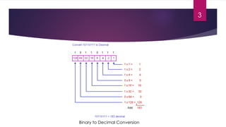
  • 3. Binary to Decimal Conversion 3
  • 4. Logic Gates u It is the building block of all digital systems. u They implement the basic Boolean operations like AND, OR, NOT, XOR, etc. 4
  • 5. Combinational Circuits u The output depends only on a combination of the present inputs. u Because of its dependence only on the present inputs, there is no feedback loop involved. u Examples include adders, multipliers, multiplexers, encoders, PLA, PLDs, etc. 5
  • 7. Sequential Circuits u Sequential Circuits the inputs depend on present as well as past inputs. u Sequential Circuits involve combinational blocks of logic and memory elements. u Examples include flip flops, FSM, RAM, etc. u Sequential Circuits are of two types: u Synchronous: They output changes are synchronized to edges of the clock (positive/rising edge or negative/falling edge) u Asynchronous: The output changes are triggered by the value of the clock(high or low), i.e., it is level sensitive. 7
  • 8. 8 Asynchronous vs Synchronous Circuits – Timing Diagram
  • 9. Finite State Machines (FSMs) u Its is generally used to control the behavior of systems and dataflow paths. u It is typically implemented in control units in the digital system. u It consists of multiple states, with each state being associated with a particular function or condition. u Eg. The system may go into low power mode when it is in ‘IDLE’ state and so on. u Depending on the state, different events/functions may be triggered. u Eg. When registers are full, the FSM can enter the ‘OVERLOAD’ state. Upon entering the OVERLOAD state, we can force the processor to put a hold on any future instructions to be executed until any registers are freed up. u There are two types of FSMs, Moore and Mealey. 9
  • 10. 10 An FSM used to control the Data Link Layer of a PCIe Gen3 Link
  • 11. Modern Digital Design u Modern Digital Design uses the concept of Datapath and Control Units. u The Datapath include functional blocks like ALUs. u The Control Units are typically implemented as FSMs. 11
  • 12. 12 An Example of Datapath and Control Unit of a Processor
  • 13. Verilog u During the early days of IC Design, engineers drew the circuits by hand. u This was a very difficult, complex, time consuming and error prone process. u VHDL was introduced in order to simplify this process. u The idea behind this is that the designer will “describe” the circuit using the HDL and the tools would infer a circuit that matches the designers intent. u Verilog was later designed in order to make the Hardware Description Language (HDL) more robust. 13
  • 14. Verilog vs Conventional Programming Languages u Verilog is used to describe hardware, while programming languages are instructions for the hardware to do certain tasks. u Verilog is a concurrent(parallel) language. u The above code would infer two separate “AND” logic gates, while a similar statement in C++ would merely “and” the values of the variables. u In C++, the value of ‘A’ will be calculated first and then the value of ‘D’ will be calculated 14
  • 15. Types of Modelling: u There are three types of modelling in Verilog: u Gate Level Modelling u Behavioral Modelling u Dataflow Modelling u Switch Level Modelling u RTL or Register transfer level is a mixture of behavioral and dataflow modelling that is used for designing synthesizable circuits. u RTL models the dataflow between registers and logical operations performed on the data. 15
  • 16. Gate Level Modelling u It is practically the lowest level of abstraction as switch level is rarely used. u It is used to implement modules in the lower levels of hierarchy like adders, multipliers, etc. u Here the connection between the pins of the logic gates are manually specified. u Netlist obtained from synthesis tools are generally gate level models in Verilog. 16
  • 17. A NAND gate designed using AND & NOT gates using gate level modelling in Verilog. 17
  • 18. Behavioral Level Modelling u It is one of the highest level of abstraction provided by Verilog. u Procedural blocks and ‘reg’ variables are used the describe the behavior of the intended hardware. u Other statements like case, if, loops are used to model the behavior of the hardware. u It is not necessarily synthesizable. 18
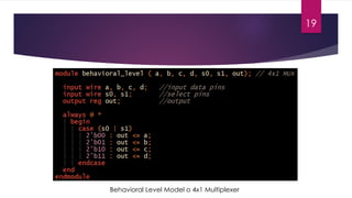
  • 19. Behavioral Level Model o 4x1 Multiplexer 19
  • 20. Dataflow Modelling u This involves the use of operators to model the flow of data in the digital system, mainly using assign statements. u It is mainly used for designing combinational circuits. u It is always synthesizable. 20
  • 21. 2x1 Multiplexer using Dataflow Modelling 21
  • 22. Switch Level Modelling u This is the lowest level of modelling in Verilog. u It is similar to gate level modelling except that connections between the pins of the transistor is specified(like gate, drain ,etc.) u It involves the use of transistor primitives. 22
  • 23. NOT gate using Switch Level Modelling 23
  • 24. References u Morris Mano Digital Design 5th edition u www.chipverify.com u www.asic-world.com u PCI Express Technology 3.0 - Mindshare 24