Basics of DWDM Technology
Download as PPTX, PDF45 likes19,867 views

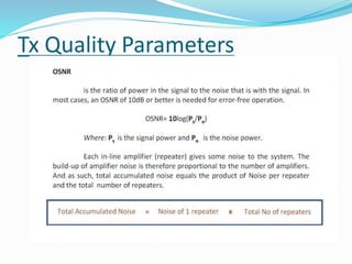
1) DWDM combines multiple optical signals so that they can be amplified and transmitted over a single fiber, increasing network capacity. 2) Basic DWDM system components include terminal multiplexers and demultiplexers, line repeaters, and optical terminals. Optical add-drop multiplexers allow removal or insertion of wavelengths along the span. 3) Proper link budgeting is required to ensure optical power levels remain above minimum thresholds to maintain signal quality as light propagates long distances through fiber. Regular monitoring and troubleshooting helps ensure transmission quality parameters are met.


Basics of DWDM Technology
- 1. 1) Introduction 2) Need of DWDM Transmission technology 3) Types of DWDM 4)Basic components of DWDM 3)NE Type/Structure 5)Transmission quality parameters 4)Equipment Alarms of 1626 LM 5)Fault Troubleshooting of 1626 LM 6)Link Budget & Power loss designing
- 2. For singlemode fiber, the loss is about 0.5 dB per km for 1310 nm sources, 0.4 dB per km for 1550 nm
- 4. Introduction
- 5. Multiplexing techniques 1) Space Division Multiplexing 2) Time Division Multiplexing 3) Wavelength Division Multiplexing
- 9. Why we need DWDM? Earlier we use SDH transmission technology where optical signals transmitted through a optical fiber utilizing only single dedication bandwidth like STM-1,4,16 & 64, by implementing SDH technology we have wasted maximum amount of bandwidth which we can utilize only by a technology known as DWDM. Definition of DWDM:-> DWDM is a transmission technology by which we can transmit/multiplex/Demux different wavelengths on a single fiber by which we can utilize maximum bandwidth via optical fiber cable. OR DWDM combines multiple optical signals so that they can amplified as a group & transported over a single fiber to increase capacity.
- 10. ITU-T BAND Band Description Wavelength Range O band original 1260 to 1360 nm E band extended 1360 to 1460 nm S band short wavelengths 1460 to 1530 nm C band conventional ("erbium window") 1530 to 1565 nm L band long wavelengths 1565 to 1625 nm U band ultralong wavelengths 1625 to 1675 nm Historically, there was a window used below the O band, called the first window, at 800-900 nm; however, losses are high in this region so this window is used primarily for short-distance communications. The current lower windows (O and E) around 1300 nm have much lower losses. This region has zero dispersion. The middle windows (S and C) around 1500 nm are the most widely used. This region has the lowest attenuation losses and achieves the longest range. It does have some dispersion, so dispersion compensator devices are used to remove this.
- 11. • The minimum frequency separation between two different multiplexed signals is known as the Channel Spacing. Since the wavelength of operation is inversely proportional to the frequency, a corresponding difference is introduced in the wavelength of each signal.
- 13. C M D X B M D X L O F A D C U T R A N S P O N D E R 96 TRBD/C CARD require to provide full capacity of 96 Lamada 12*CMDX 1*BMDX
- 15. Late 1990’s Mid 1990’s Early 1990’s 1980’s 64 to 160 channels in 1550 nm window Next generation DWDM system Channel spacing of 0.2 to 0.4 nm 16 to 40 channels in 1550nm window DWDM (Dense wdm) Channel spacing of 0.8 to 1.6 2 to 8 channels in 1550nm window Passive (or) 2nd generation WDM Channel spacing of~ 3.2nm 2 channels WWDM (Wideband WDM) 1310nm & 1550nm
- 17. *A basic DWDM system contains several main components: (a) A DWDM terminal multiplexer (b) An intermediate line repeater (c) An intermediate optical terminal (d) A DWDM terminal demultiplexer (e) Optical Supervisory Channel (OSC)
- 19. •Wavelength converting transponders translate the transmitted wavelength of a client-layer signal into one of the DWDM system's equivalent internal wavelengths. •In the mid-1990s,wavelength converting transponders rapidly took on the additional function of signal regeneration. Signal regeneration in transponders quickly evolved through 1R to 2R to 3R . 1R 2R 3R Retransmission Re-time, Re-transmit Re-time, Re-transmit, Re-shape
- 20. • Capacity increase : Large aggregate transmission capacity. • Upgradability : Customer growth without requiring additional fiber to be laid. • Flexibility : Optical Add/Drop Multiplexing (OADM) Optical Cross connect (OXC) • Scalability : The possibility to add new nodes to the network. • Network Transparency : Independence of data rate, format & protocols.
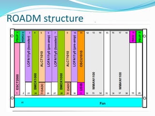
- 23. ROADM Structure
- 24. BAND-OADM
- 25. Small-OADM
- 26. ROADM
- 27. Line Terminal MUX 1626 for LH App
- 28. 1626 view as regional application
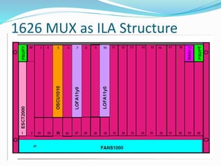
- 29. 1626 MUX as ILA Structure
- 30. ROADM structure
- 31. Main Features of 1626 LM R-4
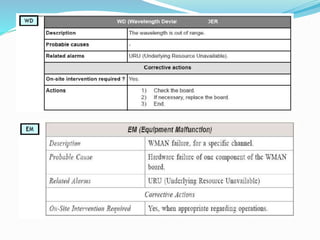
- 32. Equipment alarms
- 50. Types of Patch Cords
- 53. DWDM Components
- 57. Types of Optical Amplifier
- 59. Between multiplexing and de-multiplexing points in a DWDM system, there is an area in which multiple wavelengths exist. It is often desirable to be able to remove or insert one or more wavelengths at some point along this span. An Optical Add-Drop Multiplexer (OADM) performs this function. Rather than combining or separating all wavelengths, the OADM can remove some while passing others on. OADMs are a key part of moving toward the goal of all-optical networks.
- 60. Types of OADMs 1)Conventional OADMs- Used to drop fixed wavelength/Lamda--- where optical signal transmitted from more than one directions. 2)ROADM-> Reconfigurable OADM—used where optical signal transmitted from more than two directions.
- 69. Optical Spectrum Analyzer An Optical Spectrum Analyzer (or OSA) is a precision instrument designed to measure and display the distribution of power of an optical source over a specified wavelength span. An OSA trace displays power in the vertical scale and the wavelength in the horizontal scale. Power (dB) Wavelength(nm)
- 73. LINK BUDGETING
- 74. 1)Optical Transmit Power(Tx)-Optical Receive Power(Rx)= is called a Total LOSS of a Link. 2) Planning team will define Beginning of Life (BOL) of a link & End of life (EOL) based on the total distance of a link and type of fiber quality. 3)FOR PROPER WORKING OF A DWDM NETWORK ONE MUST HAVE TO BE MAINTAIN DWDM LINK LOSS BELOW BOL & EOL.
- 75. @Thank You@