Service Repair Manual
Models
308E2 Mini Hydraulic Excavator
NOTICE
Keep all parts clean from contaminants.
Contaminants may cause rapid wear and shortened component life.
Illustration 1 g02794543
1. Remove two bolts (2) from flywheel (1).
Illustration 2 g02798921
2. Install Tooling (A) into the crankshaft.
3. Install Tooling (B) and a suitable lifting device on flywheel (1). The weight of flywheel (1)
is approximately 30 kg (66 lb).
4. Remove remaining bolts (2).
5. Remove flywheel (1) from the cylinder block.
3/6
308E2 Mini Hydraulic Excavator F8C00001-UP (MACHINE) POWERED BY C3.3B ...
2020/1/11
https://127.0.0.1/sisweb/sisweb/techdoc/techdoc_print_page.jsp?returnurl=/sis...
Illustration 3 g02798923
6. Inspect flywheel (1) and the ring gear (3) for wear and damage. Replace any worn
components or damaged components.
7. If necessary, remove the flywheel ring gear (3), follow Step 7.a through Step 7.b.
a. Place the flywheel assembly on a suitable support.
b. Use a hammer and a punch in order to remove ring gear (3) from flywheel (1). If
necessary, a torch may be needed to heat ring gear (3).
Note: Identify the orientation of the teeth on the flywheel ring gear (3).
Installation Procedure
Table 2
Required Tools
Tool Part Number Part Description Qty
A -
Guide Stud
M12 - 1.25 by 100 mm
2
B 138-7573 Link Bracket 1
NOTICE
Keep all parts clean from contaminants.
Contaminants may cause rapid wear and shortened component life.
4/6
308E2 Mini Hydraulic Excavator F8C00001-UP (MACHINE) POWERED BY C3.3B ...
2020/1/11
https://127.0.0.1/sisweb/sisweb/techdoc/techdoc_print_page.jsp?returnurl=/sis...
Illustration 4 g02798923
Always wear protective gloves when handling parts that have been
heated.
1. If flywheel ring gear (3) was removed, follow Step 1.a through Step 1.c in order to install
ring gear (3) to flywheel (1).
a. Identify the orientation of teeth on new ring gear (3).
Note: The chamfered side of ring gear teeth must face toward the starting motor when
the flywheel is installed. This position will ensure the correct engagement of the
starting motor.
b. Raise heat of flywheel ring gear (3) in an oven to a maximum temperature of 250 °C
(482 °F) prior to installation.
Note: Do not use a torch to heat the ring gear.
c. Ensure that the orientation of ring gear (3) is correct and quickly install the ring gear
onto flywheel (1).
5/6
308E2 Mini Hydraulic Excavator F8C00001-UP (MACHINE) POWERED BY C3.3B ...
2020/1/11
https://127.0.0.1/sisweb/sisweb/techdoc/techdoc_print_page.jsp?returnurl=/sis...
Illustration 5 g02798921
2. Install Tooling (B) and a suitable lifting device on flywheel (1). The weight of flywheel (1)
is approximately 30 kg (66 lb).
3. Install Tooling (A) into the crankshaft.
4. Use the lifting device to position flywheel (1) onto Tooling (A).
5. Install bolts (2) to flywheel (1).
6. Remove Tooling (A).
Illustration 6 g02794543
7. Install remaining bolts (2) to flywheel (1). Apply engine oil to bolts. Tighten bolts (2) to a
torque of 98 to 107 N·m (72 to 80 lb ft).
8. Check the run out of the flywheel. Refer to Specifications, "Flywheel" for further
information.
Copyright 1993 - 2020 Caterpillar Inc.
All Rights Reserved.
Private Network For SIS Licensees.
Sat Jan 11 16:08:07 UTC+0800 2020
6/6
308E2 Mini Hydraulic Excavator F8C00001-UP (MACHINE) POWERED BY C3.3B ...
2020/1/11
https://127.0.0.1/sisweb/sisweb/techdoc/techdoc_print_page.jsp?returnurl=/sis...
Shutdown SIS
Previous Screen
Product: MINI HYD EXCAVATOR
Model: 308E2 MINI HYD EXCAVATOR F8C
Configuration: 308E2 Mini Hydraulic Excavator F8C00001-UP (MACHINE) POWERED BY C3.3B Engine
Disassembly and Assembly
C2.6 and C3.3B Engines for Caterpillar Built Machines
Media Number -UENR0137-11 Publication Date -01/08/2015 Date Updated -12/07/2018
i05242534
Flywheel - Remove and Install - C2.6
SMCS - 1156-010
S/N - CE21-UP
S/N - F8C1-UP
S/N - FHL1-UP
S/N - H1Y1-UP
Removal Procedure
Table 1
Required Tools
Tool Part Number Part Description Qty
A 138-7573 Link Bracket 1
Note: Refer to Specification UENR0995 "Engine Design" for non-specified engine Torque
Values.
1/4
308E2 Mini Hydraulic Excavator F8C00001-UP (MACHINE) POWERED BY C3.3B ...
2020/1/11
https://127.0.0.1/sisweb/sisweb/techdoc/techdoc_print_page.jsp?returnurl=/sis...
Illustration 1 g03202621
1. Install Tooling (A) on to flywheel (1).
2. The weight of flywheel (1) is approximately 30 kg (66 lb). Attach a suitable lifting device to
Tooling (A). Remove bolts (2) and remove flywheel (1).
Illustration 2 g03202713
3. Inspect flywheel (1) and the ring gear (3) for wear and damage. Replace any worn
components or damaged components.
4. If necessary, remove the flywheel ring gear (3), follow Step 4.a through Step 4.b.
a. Place the flywheel assembly on a suitable support.
b. Use a hammer and a punch in order to remove ring gear (3) from flywheel (1). If
necessary, a torch may be needed to heat ring gear (3).
Note: Identify the orientation of the teeth on the flywheel ring gear (3).
Installation Procedure
Table 2
Required Tools
Tool Part Number Part Description Qty
2/4
308E2 Mini Hydraulic Excavator F8C00001-UP (MACHINE) POWERED BY C3.3B ...
2020/1/11
https://127.0.0.1/sisweb/sisweb/techdoc/techdoc_print_page.jsp?returnurl=/sis...
A 138-7573 Link Bracket 1
Illustration 3 g03202713
Always wear protective gloves when handling parts that have been
heated.
1. If flywheel ring gear (3) was removed, follow Step 1.a through Step 1.c in order to install
ring gear (3) to flywheel (1).
a. Identify the orientation of teeth on new ring gear (3).
Note: The chamfered side of ring gear teeth must face toward the starting motor when
the flywheel is installed. This position will ensure the correct engagement of the
starting motor.
b. Raise the temperature of flywheel ring gear (3) in an oven to a maximum temperature
of 250 °C (482 °F) prior to installation.
Note: Do not use a torch to raise the temperature of ring gear.
c. Ensure that the orientation of ring gear (3) is correct and quickly install the ring gear
onto flywheel (1).
3/4
308E2 Mini Hydraulic Excavator F8C00001-UP (MACHINE) POWERED BY C3.3B ...
2020/1/11
https://127.0.0.1/sisweb/sisweb/techdoc/techdoc_print_page.jsp?returnurl=/sis...
Illustration 4 g03202721
2. Install Tooling (A) and a suitable lifting device on flywheel (1). The weight of flywheel (1)
is approximately 30 kg (66 lb).
3. Use the lifting device to position flywheel (1) onto crankshaft.
4. Apply clean engine oil to the threads of bolts (2). Install bolts (2) to flywheel (1). Tighten
bolts (2) to a torque of 98 to 107 N·m (72 to 80 lb ft).
5. Remove Tooling (A).
6. Check the run out of the flywheel. Refer to Specifications, "Flywheel" for further
information.
Copyright 1993 - 2020 Caterpillar Inc.
All Rights Reserved.
Private Network For SIS Licensees.
Sat Jan 11 16:09:03 UTC+0800 2020
4/4
308E2 Mini Hydraulic Excavator F8C00001-UP (MACHINE) POWERED BY C3.3B ...
2020/1/11
https://127.0.0.1/sisweb/sisweb/techdoc/techdoc_print_page.jsp?returnurl=/sis...
Shutdown SIS
Previous Screen
Product: MINI HYD EXCAVATOR
Model: 308E2 MINI HYD EXCAVATOR F8C
Configuration: 308E2 Mini Hydraulic Excavator F8C00001-UP (MACHINE) POWERED BY C3.3B Engine
Disassembly and Assembly
C2.6 and C3.3B Engines for Caterpillar Built Machines
Media Number -UENR0137-11 Publication Date -01/08/2015 Date Updated -12/07/2018
i05242540
Crankshaft Rear Seal and Wear Sleeve - Remove - Includes
Crankshaft Gear
SMCS - 1161-011; 7558-011
Removal Procedure
Start By:
a. Remove the flywheel.
NOTICE
Keep all parts clean from contaminants.
Contaminants may cause rapid wear and shortened component life.
1. Place the engine at top dead center.
1/2
308E2 Mini Hydraulic Excavator F8C00001-UP (MACHINE) POWERED BY C3.3B ...
2020/1/11
https://127.0.0.1/sisweb/sisweb/techdoc/techdoc_print_page.jsp?returnurl=/sis...
Illustration 1 g02799897
2. Use a screw driver to remove rear seal (1).
Illustration 2 g02799899
3. Check the alignment of crankshaft gear (2) and camshaft gear (3). Remove crankshaft gear
(2) and ring seal.
Illustration 3 g02799901
4. Place crankshaft gear (2) with wear sleeve (4) in a suitable vice. Remove wear sleeve (4)
with a suitable chisel.
Copyright 1993 - 2020 Caterpillar Inc.
All Rights Reserved.
Private Network For SIS Licensees.
Sat Jan 11 16:10:00 UTC+0800 2020
2/2
308E2 Mini Hydraulic Excavator F8C00001-UP (MACHINE) POWERED BY C3.3B ...
2020/1/11
https://127.0.0.1/sisweb/sisweb/techdoc/techdoc_print_page.jsp?returnurl=/sis...
Shutdown SIS
Previous Screen
Product: MINI HYD EXCAVATOR
Model: 308E2 MINI HYD EXCAVATOR F8C
Configuration: 308E2 Mini Hydraulic Excavator F8C00001-UP (MACHINE) POWERED BY C3.3B Engine
Disassembly and Assembly
C2.6 and C3.3B Engines for Caterpillar Built Machines
Media Number -UENR0137-11 Publication Date -01/08/2015 Date Updated -12/07/2018
i05242547
Crankshaft Rear Seal and Wear Sleeve - Install - Includes
Crankshaft Gear
SMCS - 1161-012; 7558-012
Installation Procedure
Table 1
Required Tools
Tool Part Number Part Description Qty
A
390-1146 Crankshaft Rear Seal and Wear Sleeve Driver(1)
1
423-9665 Crank shaft Rear Seal and Wear Sleeve Driver(2)
1
(1)
Used for the C3.3B
(2)
Used for the C2.6
Note: Refer to Specification UENR0995 "Engine Design" for non-specified engine Torque
Values.
1/2
308E2 Mini Hydraulic Excavator F8C00001-UP (MACHINE) POWERED BY C3.3B ...
2020/1/11
https://127.0.0.1/sisweb/sisweb/techdoc/techdoc_print_page.jsp?returnurl=/sis...
Illustration 1 g02800138
1. Place wear sleeve (4) on crankshaft gear (2). Position Tooling (A). Use a suitable press and
install wear sleeve (4).
Illustration 2 g02799899
2. Align crankshaft gear (2) with camshaft gear (3). Install crankshaft gear (2) into the
flywheel housing.
Illustration 3 g02800140
3. Apply clean engine oil on the lip of crankshaft rear seal (1). Use Tooling (A) in order to
install crankshaft rear seal (1).
End By:
a. Install the flywheel.
Copyright 1993 - 2020 Caterpillar Inc.
All Rights Reserved.
Private Network For SIS Licensees.
Sat Jan 11 16:10:57 UTC+0800 2020
2/2
308E2 Mini Hydraulic Excavator F8C00001-UP (MACHINE) POWERED BY C3.3B ...
2020/1/11
https://127.0.0.1/sisweb/sisweb/techdoc/techdoc_print_page.jsp?returnurl=/sis...
Shutdown SIS
Previous Screen
Product: MINI HYD EXCAVATOR
Model: 308E2 MINI HYD EXCAVATOR F8C
Configuration: 308E2 Mini Hydraulic Excavator F8C00001-UP (MACHINE) POWERED BY C3.3B Engine
Disassembly and Assembly
C2.6 and C3.3B Engines for Caterpillar Built Machines
Media Number -UENR0137-11 Publication Date -01/08/2015 Date Updated -12/07/2018
i05242551
Flywheel Housing - Remove and Install
SMCS - 1157-010
Removal Procedure
Table 1
Required Tools
Tool Part Number Part Description Qty
A -
Guide Stud
M12 x 1.25 by 100 mm
2
B 138-7575 Link Brackets 2
Start By:
a. Remove the flywheel.
b. Remove the rear crankshaft seal.
Note: Refer to Specification UENR0995 "Engine Design" for non-specified engine Torque
Values.
NOTICE
Keep all parts clean from contaminants.
Contaminants may cause rapid wear and shortened component life.
1/3
308E2 Mini Hydraulic Excavator F8C00001-UP (MACHINE) POWERED BY C3.3B ...
2020/1/11
https://127.0.0.1/sisweb/sisweb/techdoc/techdoc_print_page.jsp?returnurl=/sis...
Illustration 1 g02794824
1. Remove two bolts (3) from flywheel housing (1).
2. Install Tooling (A) into flywheel housing (1).
3. Install Tooling (B). Install a suitable lifting device to flywheel housing (1). The weight of
flywheel housing (1) is approximately 25 kg (55 lb).
4. Remove remaining six bolts (3) and 8 bolts (2) from flywheel housing (1).
5. Remove flywheel housing (1) from the cylinder block.
Illustration 2 g02794825
6. Remove bearing (4).
7. Remove the gasket (5).
8. If necessary, remove the dowels from the cylinder block.
Installation Procedure
1. Install flywheel housing (1) in the reverse order of removal.
2/3
308E2 Mini Hydraulic Excavator F8C00001-UP (MACHINE) POWERED BY C3.3B ...
2020/1/11
https://127.0.0.1/sisweb/sisweb/techdoc/techdoc_print_page.jsp?returnurl=/sis...
Illustration 3 g02863884
a. Install liquid gasket to the seam between the lower crankcase section (7) and the
upper crankcase section (6).
b. For the C3.3B tighten 8 bolts (3) and 8 bolts (2) to a torque of 103 to 117 N·m
(76 to 87 lb ft).
c. For the C2.6 tighten 8 bolts (3) and 8 bolts (2) to a torque of 78 to 90 N·m
(58 to 66 lb ft).
Copyright 1993 - 2020 Caterpillar Inc.
All Rights Reserved.
Private Network For SIS Licensees.
Sat Jan 11 16:11:54 UTC+0800 2020
3/3
308E2 Mini Hydraulic Excavator F8C00001-UP (MACHINE) POWERED BY C3.3B ...
2020/1/11
https://127.0.0.1/sisweb/sisweb/techdoc/techdoc_print_page.jsp?returnurl=/sis...
Shutdown SIS
Previous Screen
Product: MINI HYD EXCAVATOR
Model: 308E2 MINI HYD EXCAVATOR F8C
Configuration: 308E2 Mini Hydraulic Excavator F8C00001-UP (MACHINE) POWERED BY C3.3B Engine
Disassembly and Assembly
C2.6 and C3.3B Engines for Caterpillar Built Machines
Media Number -UENR0137-11 Publication Date -01/08/2015 Date Updated -12/07/2018
i05242553
Crankshaft Pulley - Remove and Install
SMCS - 1205-010
Removal Procedure
Start By:
a. Remove the v-belt.
Note: Refer to Specification UENR0995 "Engine Design" for non-specified engine Torque
Values.
NOTICE
Keep all parts clean from contaminants.
Contaminants may cause rapid wear and shortened component life.
1/2
308E2 Mini Hydraulic Excavator F8C00001-UP (MACHINE) POWERED BY C3.3B ...
2020/1/11
https://127.0.0.1/sisweb/sisweb/techdoc/techdoc_print_page.jsp?returnurl=/sis...
Thank you very much for
your reading. Please Click
Here. Then Get COMPLETE
MANUAL. NO WAITING
NOTE:
If there is no response to
click on the link above,
please download the PDF
document first and then
click on it.
Illustration 1 g02795206
1. Use a suitable tool in order to prevent the crankshaft from rotating. Remove bolt (2) in order
to remove crankshaft pulley (1).
Installation Procedure
1. Install crankshaft pulley (1) in the reverse order of removal.
a. Apply clean engine oil to the threads of bolt (2). Tighten bolt (2) to a torque of
255 to 274 N·m (188 to 202 lb ft).
Copyright 1993 - 2020 Caterpillar Inc.
All Rights Reserved.
Private Network For SIS Licensees.
Sat Jan 11 16:12:50 UTC+0800 2020
2/2
308E2 Mini Hydraulic Excavator F8C00001-UP (MACHINE) POWERED BY C3.3B ...
2020/1/11
https://127.0.0.1/sisweb/sisweb/techdoc/techdoc_print_page.jsp?returnurl=/sis...
Shutdown SIS
Previous Screen
Product: MINI HYD EXCAVATOR
Model: 308E2 MINI HYD EXCAVATOR F8C
Configuration: 308E2 Mini Hydraulic Excavator F8C00001-UP (MACHINE) POWERED BY C3.3B Engine
Disassembly and Assembly
C2.6 and C3.3B Engines for Caterpillar Built Machines
Media Number -UENR0137-11 Publication Date -01/08/2015 Date Updated -12/07/2018
i05242559
Crankshaft Front Seal - Remove and Install
SMCS - 1160-010
Removal Procedure
Start By:
a. Remove the crankshaft pulley.
Note: Refer to Specification UENR0995 "Engine Design" for non-specified engine Torque
Values.
NOTICE
Care must be taken to ensure that fluids are contained during
performance of inspection, maintenance, testing, adjusting and repair
of the product. Be prepared to collect the fluid with suitable containers
before opening any compartment or disassembling any component
containing fluids.
Dispose of all fluids according to local regulations and mandates.
1/3
308E2 Mini Hydraulic Excavator F8C00001-UP (MACHINE) POWERED BY C3.3B ...
2020/1/11
https://127.0.0.1/sisweb/sisweb/techdoc/techdoc_print_page.jsp?returnurl=/sis...
Illustration 1 g02795123
Illustration 2 g02795124
1. Use a suitable pry bar to remove crankshaft front seal (1).
Installation Procedure
Table 1
Required Tools
Tool Part Number Part Description Qty
A 390-1140 Driver 1
B 6V-6640 Sealant 1
Note: The crankshaft front seal should be installed dry. Lubricate the inner rubber portion of the
crankshaft front seal.
2/3
308E2 Mini Hydraulic Excavator F8C00001-UP (MACHINE) POWERED BY C3.3B ...
2020/1/11
https://127.0.0.1/sisweb/sisweb/techdoc/techdoc_print_page.jsp?returnurl=/sis...
Illustration 3 g02796112
Illustration 4 g02795123
1. Lubricate the inner rubber portion of crankshaft front seal (1). Apply Tooling (B) on
crankshaft front seal (1). Position crankshaft front seal (1) on Tooling (A). Install crankshaft
front seal (1) on the crankshaft.
End By:
a. Install the crankshaft pulley.
Copyright 1993 - 2020 Caterpillar Inc.
All Rights Reserved.
Private Network For SIS Licensees.
Sat Jan 11 16:13:47 UTC+0800 2020
3/3
308E2 Mini Hydraulic Excavator F8C00001-UP (MACHINE) POWERED BY C3.3B ...
2020/1/11
https://127.0.0.1/sisweb/sisweb/techdoc/techdoc_print_page.jsp?returnurl=/sis...

More Related Content

PDF
Caterpillar cat 308 e2 mini hydraulic excavator (prefix f8c) service repair m...
PDF
Caterpillar cat 308 e2 mini hydraulic excavator (prefix f8c) service repair m...
PDF
Caterpillar Cat 308E2 Mini Hydraulic Excavator (Prefix F8C) Service Repair Ma...
PDF
Caterpillar Cat 308E2 Mini Hydraulic Excavator (Prefix F8C) Service Repair Ma...
PDF
Caterpillar Cat 308E2 Mini Hydraulic Excavator (Prefix F8C) Service Repair Ma...
PDF
Caterpillar Cat 308E2 Mini Hydraulic Excavator (Prefix F8C) Service Repair Ma...
PDF
Caterpillar Cat 308E2 Mini Hydraulic Excavator (Prefix F8C) Service Repair Ma...
PDF
Caterpillar Cat 262D Skid Steer Loader (Prefix AJ7) Service Repair Manual (AJ...
Caterpillar cat 308 e2 mini hydraulic excavator (prefix f8c) service repair m...
Caterpillar Cat 308E2 Mini Hydraulic Excavator (Prefix F8C) Service Repair Ma...
Caterpillar Cat 262D Skid Steer Loader (Prefix AJ7) Service Repair Manual (AJ...

Similar to Caterpillar Cat 308E2 Mini Hydraulic Excavator (Prefix F8C) Service Repair Manual (F8C00001 and up).pdf (14)

PDF
Caterpillar Cat 262D Skid Steer Loader (Prefix AJ7) Service Repair Manual (AJ...
PDF
Caterpillar Cat 262D Skid Steer Loader (Prefix AJ7) Service Repair Manual (AJ...
PDF
Caterpillar Cat 262D Skid Steer Loader (Prefix AJ7) Service Repair Manual (AJ...
PDF
Caterpillar Cat 262D Skid Steer Loader (Prefix AJ7) Service Repair Manual (AJ...
PDF
Caterpillar Cat 262D Skid Steer Loader (Prefix AJ7) Service Repair Manual (AJ...
PDF
Caterpillar Cat 262D Skid Steer Loader (Prefix AJ7) Service Repair Manual (AJ...
PDF
Caterpillar Cat 262D Skid Steer Loader (Prefix AJ7) Service Repair Manual (AJ...
PDF
Caterpillar Cat 262D Skid Steer Loader (Prefix AJ7) Service Repair Manual (AJ...
PDF
Caterpillar Cat 262D Skid Steer Loader (Prefix AJ7) Service Repair Manual (AJ...
PDF
Caterpillar Cat 262D Skid Steer Loader (Prefix AJ7) Service Repair Manual (AJ...
PDF
Caterpillar Cat 262D Skid Steer Loader (Prefix AJ7) Service Repair Manual (AJ...
PDF
Caterpillar Cat 262D Skid Steer Loader (Prefix AJ7) Service Repair Manual (AJ...
PDF
Caterpillar Cat 262D Skid Steer Loader (Prefix AJ7) Service Repair Manual (AJ...
PDF
Caterpillar Cat 262D Skid Steer Loader (Prefix AJ7) Service Repair Manual (AJ...

More from 7fdsjkddmmdm (20)

PDF
Caterpillar Cat D25D ARTICULATED TRUCK (Prefix 3AJ) Service Repair Manual (3A...
PDF
New Holland TN75 Tractor Service Repair Manual.pdf
PDF
New Holland TN65 Tractor Service Repair Manual.pdf
PDF
New Holland TN70 Tractor Service Repair Manual.pdf
PDF
New Holland TN55 Tractor Service Repair Manual.pdf
PDF
Caterpillar Cat D30D ARTICULATED TRUCK (Prefix 3AJ) Service Repair Manual (3A...
PDF
Caterpillar Cat D8N TRACK-TYPE TRACTOR Dozer Bulldozer (Prefix 7TK) Service R...
PDF
Caterpillar Cat D8L TRACK-TYPE TRACTOR Dozer Bulldozer (Prefix 7YB) Service R...
PDF
Caterpillar Cat 3054B Industrial Engine (Prefix 5MF) Service Repair Manual (5...
PDF
Caterpillar Cat 740 OEM Articulated Truck (Prefix WWD) Service Repair Manual ...
PDF
Caterpillar Cat 740 Ejector Articulated Truck (Prefix B1R) Service Repair Man...
PDF
Caterpillar Cat 725 OEM Articulated Truck (Prefix WWA) Service Repair Manual ...
PDF
Caterpillar Cat 450F BACKHOE LOADER (Prefix HJR) Service Repair Manual (HJR00...
PDF
Caterpillar Cat 432F2 BACKHOE LOADER (Prefix LYJ) Service Repair Manual (LYJ0...
PDF
Caterpillar Cat 430F2 Backhoe Loader (Prefix HWE) Service Repair Manual (HWE0...
PDF
Caterpillar Cat 322L EXCAVATOR (Prefix 8CL) Service Repair Manual (8CL00001 a...
PDF
Caterpillar Cat 322 EXCAVATOR (Prefix 8CL) Service Repair Manual (8CL00001 an...
PDF
CASE DV207 Vibratory Roller Service Repair Manual.pdf
PDF
Caterpillar Cat 320E LRR Excavator (Prefix TFX) Service Repair Manual (TFX000...
PDF
CASE DV207HF Vibratory Roller Service Repair Manual.pdf
Caterpillar Cat D25D ARTICULATED TRUCK (Prefix 3AJ) Service Repair Manual (3A...
New Holland TN75 Tractor Service Repair Manual.pdf
New Holland TN65 Tractor Service Repair Manual.pdf
New Holland TN70 Tractor Service Repair Manual.pdf
New Holland TN55 Tractor Service Repair Manual.pdf
Caterpillar Cat D30D ARTICULATED TRUCK (Prefix 3AJ) Service Repair Manual (3A...
Caterpillar Cat D8N TRACK-TYPE TRACTOR Dozer Bulldozer (Prefix 7TK) Service R...
Caterpillar Cat D8L TRACK-TYPE TRACTOR Dozer Bulldozer (Prefix 7YB) Service R...
Caterpillar Cat 3054B Industrial Engine (Prefix 5MF) Service Repair Manual (5...
Caterpillar Cat 740 OEM Articulated Truck (Prefix WWD) Service Repair Manual ...
Caterpillar Cat 740 Ejector Articulated Truck (Prefix B1R) Service Repair Man...
Caterpillar Cat 725 OEM Articulated Truck (Prefix WWA) Service Repair Manual ...
Caterpillar Cat 450F BACKHOE LOADER (Prefix HJR) Service Repair Manual (HJR00...
Caterpillar Cat 432F2 BACKHOE LOADER (Prefix LYJ) Service Repair Manual (LYJ0...
Caterpillar Cat 430F2 Backhoe Loader (Prefix HWE) Service Repair Manual (HWE0...
Caterpillar Cat 322L EXCAVATOR (Prefix 8CL) Service Repair Manual (8CL00001 a...
Caterpillar Cat 322 EXCAVATOR (Prefix 8CL) Service Repair Manual (8CL00001 an...
CASE DV207 Vibratory Roller Service Repair Manual.pdf
Caterpillar Cat 320E LRR Excavator (Prefix TFX) Service Repair Manual (TFX000...
CASE DV207HF Vibratory Roller Service Repair Manual.pdf

Recently uploaded (20)

PPTX
diesel comman rail diesel comman hhh rail
PDF
BOBCAT 442 muffler SN 522311001 & Above.pdf
PDF
D85PX-15E0 Komatsu d85 px 15e0 dozer bulldozer Technical manual.pdf
PDF
Designyze – Creative Digital Marketing & Design Agency in India
PPTX
APQP FOR AUTOMOTIVE AND PPAP FOR SUPPLIER
PDF
John Deere 410E service Repair Manual.pdf
PDF
Where to Buy Verified LinkedIn Accounts Securely in 2025.pdf
PPT
157_37315_EA221_2013_1__2_1_Chapter 1, introduction to OR.ppt
PPTX
IOT-UNIT 3.pptxaaaasasasasasasaasasasasas
PDF
TM1611 John Deere 410E service Repair Manual.pdf
PDF
BCM-hardware-schematics in automotive electronics.pdf
PDF
BOBCAT 442 Excavator Service Repair Manual.pdf
PDF
dozer bulldozer Komatsu d85 px 15e0 Technical manual.pdf
PPTX
Electric Vehicles vs Combustion Engine Vehicles.pptx
PDF
Deutz D6D EBE2 Volvo EC160BLC Excavator Service Repair Manual.pdf
PDF
Transmission John Deere 370E 410E 460E Technical Manual.pdf
PPTX
DNA Packaging in Eukaryot ic Cells.pptx
PDF
Presentation KSR EV Product Plan for the year of 2023
PDF
Bnmn8tf8tf8f585x85fitc8tc75f74f75f8tx8tc8tx85
PPTX
Training Material_Verification Station.pptx
diesel comman rail diesel comman hhh rail
BOBCAT 442 muffler SN 522311001 & Above.pdf
D85PX-15E0 Komatsu d85 px 15e0 dozer bulldozer Technical manual.pdf
Designyze – Creative Digital Marketing & Design Agency in India
APQP FOR AUTOMOTIVE AND PPAP FOR SUPPLIER
John Deere 410E service Repair Manual.pdf
Where to Buy Verified LinkedIn Accounts Securely in 2025.pdf
157_37315_EA221_2013_1__2_1_Chapter 1, introduction to OR.ppt
IOT-UNIT 3.pptxaaaasasasasasasaasasasasas
TM1611 John Deere 410E service Repair Manual.pdf
BCM-hardware-schematics in automotive electronics.pdf
BOBCAT 442 Excavator Service Repair Manual.pdf
dozer bulldozer Komatsu d85 px 15e0 Technical manual.pdf
Electric Vehicles vs Combustion Engine Vehicles.pptx
Deutz D6D EBE2 Volvo EC160BLC Excavator Service Repair Manual.pdf
Transmission John Deere 370E 410E 460E Technical Manual.pdf
DNA Packaging in Eukaryot ic Cells.pptx
Presentation KSR EV Product Plan for the year of 2023
Bnmn8tf8tf8f585x85fitc8tc75f74f75f8tx8tc8tx85
Training Material_Verification Station.pptx

Caterpillar Cat 308E2 Mini Hydraulic Excavator (Prefix F8C) Service Repair Manual (F8C00001 and up).pdf

  • 1. Service Repair Manual Models 308E2 Mini Hydraulic Excavator
  • 2. NOTICE Keep all parts clean from contaminants. Contaminants may cause rapid wear and shortened component life. Illustration 1 g02794543 1. Remove two bolts (2) from flywheel (1). Illustration 2 g02798921 2. Install Tooling (A) into the crankshaft. 3. Install Tooling (B) and a suitable lifting device on flywheel (1). The weight of flywheel (1) is approximately 30 kg (66 lb). 4. Remove remaining bolts (2). 5. Remove flywheel (1) from the cylinder block. 3/6 308E2 Mini Hydraulic Excavator F8C00001-UP (MACHINE) POWERED BY C3.3B ... 2020/1/11 https://127.0.0.1/sisweb/sisweb/techdoc/techdoc_print_page.jsp?returnurl=/sis...
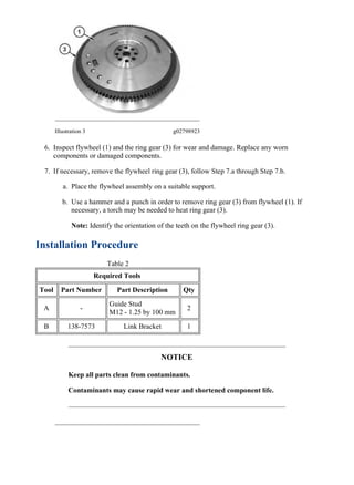
  • 3. Illustration 3 g02798923 6. Inspect flywheel (1) and the ring gear (3) for wear and damage. Replace any worn components or damaged components. 7. If necessary, remove the flywheel ring gear (3), follow Step 7.a through Step 7.b. a. Place the flywheel assembly on a suitable support. b. Use a hammer and a punch in order to remove ring gear (3) from flywheel (1). If necessary, a torch may be needed to heat ring gear (3). Note: Identify the orientation of the teeth on the flywheel ring gear (3). Installation Procedure Table 2 Required Tools Tool Part Number Part Description Qty A - Guide Stud M12 - 1.25 by 100 mm 2 B 138-7573 Link Bracket 1 NOTICE Keep all parts clean from contaminants. Contaminants may cause rapid wear and shortened component life. 4/6 308E2 Mini Hydraulic Excavator F8C00001-UP (MACHINE) POWERED BY C3.3B ... 2020/1/11 https://127.0.0.1/sisweb/sisweb/techdoc/techdoc_print_page.jsp?returnurl=/sis...
  • 4. Illustration 4 g02798923 Always wear protective gloves when handling parts that have been heated. 1. If flywheel ring gear (3) was removed, follow Step 1.a through Step 1.c in order to install ring gear (3) to flywheel (1). a. Identify the orientation of teeth on new ring gear (3). Note: The chamfered side of ring gear teeth must face toward the starting motor when the flywheel is installed. This position will ensure the correct engagement of the starting motor. b. Raise heat of flywheel ring gear (3) in an oven to a maximum temperature of 250 °C (482 °F) prior to installation. Note: Do not use a torch to heat the ring gear. c. Ensure that the orientation of ring gear (3) is correct and quickly install the ring gear onto flywheel (1). 5/6 308E2 Mini Hydraulic Excavator F8C00001-UP (MACHINE) POWERED BY C3.3B ... 2020/1/11 https://127.0.0.1/sisweb/sisweb/techdoc/techdoc_print_page.jsp?returnurl=/sis...
  • 5. Illustration 5 g02798921 2. Install Tooling (B) and a suitable lifting device on flywheel (1). The weight of flywheel (1) is approximately 30 kg (66 lb). 3. Install Tooling (A) into the crankshaft. 4. Use the lifting device to position flywheel (1) onto Tooling (A). 5. Install bolts (2) to flywheel (1). 6. Remove Tooling (A). Illustration 6 g02794543 7. Install remaining bolts (2) to flywheel (1). Apply engine oil to bolts. Tighten bolts (2) to a torque of 98 to 107 N·m (72 to 80 lb ft). 8. Check the run out of the flywheel. Refer to Specifications, "Flywheel" for further information. Copyright 1993 - 2020 Caterpillar Inc. All Rights Reserved. Private Network For SIS Licensees. Sat Jan 11 16:08:07 UTC+0800 2020 6/6 308E2 Mini Hydraulic Excavator F8C00001-UP (MACHINE) POWERED BY C3.3B ... 2020/1/11 https://127.0.0.1/sisweb/sisweb/techdoc/techdoc_print_page.jsp?returnurl=/sis...
  • 6. Shutdown SIS Previous Screen Product: MINI HYD EXCAVATOR Model: 308E2 MINI HYD EXCAVATOR F8C Configuration: 308E2 Mini Hydraulic Excavator F8C00001-UP (MACHINE) POWERED BY C3.3B Engine Disassembly and Assembly C2.6 and C3.3B Engines for Caterpillar Built Machines Media Number -UENR0137-11 Publication Date -01/08/2015 Date Updated -12/07/2018 i05242534 Flywheel - Remove and Install - C2.6 SMCS - 1156-010 S/N - CE21-UP S/N - F8C1-UP S/N - FHL1-UP S/N - H1Y1-UP Removal Procedure Table 1 Required Tools Tool Part Number Part Description Qty A 138-7573 Link Bracket 1 Note: Refer to Specification UENR0995 "Engine Design" for non-specified engine Torque Values. 1/4 308E2 Mini Hydraulic Excavator F8C00001-UP (MACHINE) POWERED BY C3.3B ... 2020/1/11 https://127.0.0.1/sisweb/sisweb/techdoc/techdoc_print_page.jsp?returnurl=/sis...
  • 7. Illustration 1 g03202621 1. Install Tooling (A) on to flywheel (1). 2. The weight of flywheel (1) is approximately 30 kg (66 lb). Attach a suitable lifting device to Tooling (A). Remove bolts (2) and remove flywheel (1). Illustration 2 g03202713 3. Inspect flywheel (1) and the ring gear (3) for wear and damage. Replace any worn components or damaged components. 4. If necessary, remove the flywheel ring gear (3), follow Step 4.a through Step 4.b. a. Place the flywheel assembly on a suitable support. b. Use a hammer and a punch in order to remove ring gear (3) from flywheel (1). If necessary, a torch may be needed to heat ring gear (3). Note: Identify the orientation of the teeth on the flywheel ring gear (3). Installation Procedure Table 2 Required Tools Tool Part Number Part Description Qty 2/4 308E2 Mini Hydraulic Excavator F8C00001-UP (MACHINE) POWERED BY C3.3B ... 2020/1/11 https://127.0.0.1/sisweb/sisweb/techdoc/techdoc_print_page.jsp?returnurl=/sis...
  • 8. A 138-7573 Link Bracket 1 Illustration 3 g03202713 Always wear protective gloves when handling parts that have been heated. 1. If flywheel ring gear (3) was removed, follow Step 1.a through Step 1.c in order to install ring gear (3) to flywheel (1). a. Identify the orientation of teeth on new ring gear (3). Note: The chamfered side of ring gear teeth must face toward the starting motor when the flywheel is installed. This position will ensure the correct engagement of the starting motor. b. Raise the temperature of flywheel ring gear (3) in an oven to a maximum temperature of 250 °C (482 °F) prior to installation. Note: Do not use a torch to raise the temperature of ring gear. c. Ensure that the orientation of ring gear (3) is correct and quickly install the ring gear onto flywheel (1). 3/4 308E2 Mini Hydraulic Excavator F8C00001-UP (MACHINE) POWERED BY C3.3B ... 2020/1/11 https://127.0.0.1/sisweb/sisweb/techdoc/techdoc_print_page.jsp?returnurl=/sis...
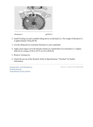
  • 9. Illustration 4 g03202721 2. Install Tooling (A) and a suitable lifting device on flywheel (1). The weight of flywheel (1) is approximately 30 kg (66 lb). 3. Use the lifting device to position flywheel (1) onto crankshaft. 4. Apply clean engine oil to the threads of bolts (2). Install bolts (2) to flywheel (1). Tighten bolts (2) to a torque of 98 to 107 N·m (72 to 80 lb ft). 5. Remove Tooling (A). 6. Check the run out of the flywheel. Refer to Specifications, "Flywheel" for further information. Copyright 1993 - 2020 Caterpillar Inc. All Rights Reserved. Private Network For SIS Licensees. Sat Jan 11 16:09:03 UTC+0800 2020 4/4 308E2 Mini Hydraulic Excavator F8C00001-UP (MACHINE) POWERED BY C3.3B ... 2020/1/11 https://127.0.0.1/sisweb/sisweb/techdoc/techdoc_print_page.jsp?returnurl=/sis...
  • 10. Shutdown SIS Previous Screen Product: MINI HYD EXCAVATOR Model: 308E2 MINI HYD EXCAVATOR F8C Configuration: 308E2 Mini Hydraulic Excavator F8C00001-UP (MACHINE) POWERED BY C3.3B Engine Disassembly and Assembly C2.6 and C3.3B Engines for Caterpillar Built Machines Media Number -UENR0137-11 Publication Date -01/08/2015 Date Updated -12/07/2018 i05242540 Crankshaft Rear Seal and Wear Sleeve - Remove - Includes Crankshaft Gear SMCS - 1161-011; 7558-011 Removal Procedure Start By: a. Remove the flywheel. NOTICE Keep all parts clean from contaminants. Contaminants may cause rapid wear and shortened component life. 1. Place the engine at top dead center. 1/2 308E2 Mini Hydraulic Excavator F8C00001-UP (MACHINE) POWERED BY C3.3B ... 2020/1/11 https://127.0.0.1/sisweb/sisweb/techdoc/techdoc_print_page.jsp?returnurl=/sis...
  • 11. Illustration 1 g02799897 2. Use a screw driver to remove rear seal (1). Illustration 2 g02799899 3. Check the alignment of crankshaft gear (2) and camshaft gear (3). Remove crankshaft gear (2) and ring seal. Illustration 3 g02799901 4. Place crankshaft gear (2) with wear sleeve (4) in a suitable vice. Remove wear sleeve (4) with a suitable chisel. Copyright 1993 - 2020 Caterpillar Inc. All Rights Reserved. Private Network For SIS Licensees. Sat Jan 11 16:10:00 UTC+0800 2020 2/2 308E2 Mini Hydraulic Excavator F8C00001-UP (MACHINE) POWERED BY C3.3B ... 2020/1/11 https://127.0.0.1/sisweb/sisweb/techdoc/techdoc_print_page.jsp?returnurl=/sis...
  • 12. Shutdown SIS Previous Screen Product: MINI HYD EXCAVATOR Model: 308E2 MINI HYD EXCAVATOR F8C Configuration: 308E2 Mini Hydraulic Excavator F8C00001-UP (MACHINE) POWERED BY C3.3B Engine Disassembly and Assembly C2.6 and C3.3B Engines for Caterpillar Built Machines Media Number -UENR0137-11 Publication Date -01/08/2015 Date Updated -12/07/2018 i05242547 Crankshaft Rear Seal and Wear Sleeve - Install - Includes Crankshaft Gear SMCS - 1161-012; 7558-012 Installation Procedure Table 1 Required Tools Tool Part Number Part Description Qty A 390-1146 Crankshaft Rear Seal and Wear Sleeve Driver(1) 1 423-9665 Crank shaft Rear Seal and Wear Sleeve Driver(2) 1 (1) Used for the C3.3B (2) Used for the C2.6 Note: Refer to Specification UENR0995 "Engine Design" for non-specified engine Torque Values. 1/2 308E2 Mini Hydraulic Excavator F8C00001-UP (MACHINE) POWERED BY C3.3B ... 2020/1/11 https://127.0.0.1/sisweb/sisweb/techdoc/techdoc_print_page.jsp?returnurl=/sis...
  • 13. Illustration 1 g02800138 1. Place wear sleeve (4) on crankshaft gear (2). Position Tooling (A). Use a suitable press and install wear sleeve (4). Illustration 2 g02799899 2. Align crankshaft gear (2) with camshaft gear (3). Install crankshaft gear (2) into the flywheel housing. Illustration 3 g02800140 3. Apply clean engine oil on the lip of crankshaft rear seal (1). Use Tooling (A) in order to install crankshaft rear seal (1). End By: a. Install the flywheel. Copyright 1993 - 2020 Caterpillar Inc. All Rights Reserved. Private Network For SIS Licensees. Sat Jan 11 16:10:57 UTC+0800 2020 2/2 308E2 Mini Hydraulic Excavator F8C00001-UP (MACHINE) POWERED BY C3.3B ... 2020/1/11 https://127.0.0.1/sisweb/sisweb/techdoc/techdoc_print_page.jsp?returnurl=/sis...
  • 14. Shutdown SIS Previous Screen Product: MINI HYD EXCAVATOR Model: 308E2 MINI HYD EXCAVATOR F8C Configuration: 308E2 Mini Hydraulic Excavator F8C00001-UP (MACHINE) POWERED BY C3.3B Engine Disassembly and Assembly C2.6 and C3.3B Engines for Caterpillar Built Machines Media Number -UENR0137-11 Publication Date -01/08/2015 Date Updated -12/07/2018 i05242551 Flywheel Housing - Remove and Install SMCS - 1157-010 Removal Procedure Table 1 Required Tools Tool Part Number Part Description Qty A - Guide Stud M12 x 1.25 by 100 mm 2 B 138-7575 Link Brackets 2 Start By: a. Remove the flywheel. b. Remove the rear crankshaft seal. Note: Refer to Specification UENR0995 "Engine Design" for non-specified engine Torque Values. NOTICE Keep all parts clean from contaminants. Contaminants may cause rapid wear and shortened component life. 1/3 308E2 Mini Hydraulic Excavator F8C00001-UP (MACHINE) POWERED BY C3.3B ... 2020/1/11 https://127.0.0.1/sisweb/sisweb/techdoc/techdoc_print_page.jsp?returnurl=/sis...
  • 15. Illustration 1 g02794824 1. Remove two bolts (3) from flywheel housing (1). 2. Install Tooling (A) into flywheel housing (1). 3. Install Tooling (B). Install a suitable lifting device to flywheel housing (1). The weight of flywheel housing (1) is approximately 25 kg (55 lb). 4. Remove remaining six bolts (3) and 8 bolts (2) from flywheel housing (1). 5. Remove flywheel housing (1) from the cylinder block. Illustration 2 g02794825 6. Remove bearing (4). 7. Remove the gasket (5). 8. If necessary, remove the dowels from the cylinder block. Installation Procedure 1. Install flywheel housing (1) in the reverse order of removal. 2/3 308E2 Mini Hydraulic Excavator F8C00001-UP (MACHINE) POWERED BY C3.3B ... 2020/1/11 https://127.0.0.1/sisweb/sisweb/techdoc/techdoc_print_page.jsp?returnurl=/sis...
  • 16. Illustration 3 g02863884 a. Install liquid gasket to the seam between the lower crankcase section (7) and the upper crankcase section (6). b. For the C3.3B tighten 8 bolts (3) and 8 bolts (2) to a torque of 103 to 117 N·m (76 to 87 lb ft). c. For the C2.6 tighten 8 bolts (3) and 8 bolts (2) to a torque of 78 to 90 N·m (58 to 66 lb ft). Copyright 1993 - 2020 Caterpillar Inc. All Rights Reserved. Private Network For SIS Licensees. Sat Jan 11 16:11:54 UTC+0800 2020 3/3 308E2 Mini Hydraulic Excavator F8C00001-UP (MACHINE) POWERED BY C3.3B ... 2020/1/11 https://127.0.0.1/sisweb/sisweb/techdoc/techdoc_print_page.jsp?returnurl=/sis...
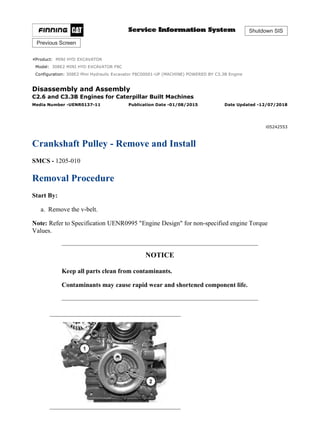
  • 17. Shutdown SIS Previous Screen Product: MINI HYD EXCAVATOR Model: 308E2 MINI HYD EXCAVATOR F8C Configuration: 308E2 Mini Hydraulic Excavator F8C00001-UP (MACHINE) POWERED BY C3.3B Engine Disassembly and Assembly C2.6 and C3.3B Engines for Caterpillar Built Machines Media Number -UENR0137-11 Publication Date -01/08/2015 Date Updated -12/07/2018 i05242553 Crankshaft Pulley - Remove and Install SMCS - 1205-010 Removal Procedure Start By: a. Remove the v-belt. Note: Refer to Specification UENR0995 "Engine Design" for non-specified engine Torque Values. NOTICE Keep all parts clean from contaminants. Contaminants may cause rapid wear and shortened component life. 1/2 308E2 Mini Hydraulic Excavator F8C00001-UP (MACHINE) POWERED BY C3.3B ... 2020/1/11 https://127.0.0.1/sisweb/sisweb/techdoc/techdoc_print_page.jsp?returnurl=/sis...
  • 18. Thank you very much for your reading. Please Click Here. Then Get COMPLETE MANUAL. NO WAITING NOTE: If there is no response to click on the link above, please download the PDF document first and then click on it.
  • 19. Illustration 1 g02795206 1. Use a suitable tool in order to prevent the crankshaft from rotating. Remove bolt (2) in order to remove crankshaft pulley (1). Installation Procedure 1. Install crankshaft pulley (1) in the reverse order of removal. a. Apply clean engine oil to the threads of bolt (2). Tighten bolt (2) to a torque of 255 to 274 N·m (188 to 202 lb ft). Copyright 1993 - 2020 Caterpillar Inc. All Rights Reserved. Private Network For SIS Licensees. Sat Jan 11 16:12:50 UTC+0800 2020 2/2 308E2 Mini Hydraulic Excavator F8C00001-UP (MACHINE) POWERED BY C3.3B ... 2020/1/11 https://127.0.0.1/sisweb/sisweb/techdoc/techdoc_print_page.jsp?returnurl=/sis...
  • 20. Shutdown SIS Previous Screen Product: MINI HYD EXCAVATOR Model: 308E2 MINI HYD EXCAVATOR F8C Configuration: 308E2 Mini Hydraulic Excavator F8C00001-UP (MACHINE) POWERED BY C3.3B Engine Disassembly and Assembly C2.6 and C3.3B Engines for Caterpillar Built Machines Media Number -UENR0137-11 Publication Date -01/08/2015 Date Updated -12/07/2018 i05242559 Crankshaft Front Seal - Remove and Install SMCS - 1160-010 Removal Procedure Start By: a. Remove the crankshaft pulley. Note: Refer to Specification UENR0995 "Engine Design" for non-specified engine Torque Values. NOTICE Care must be taken to ensure that fluids are contained during performance of inspection, maintenance, testing, adjusting and repair of the product. Be prepared to collect the fluid with suitable containers before opening any compartment or disassembling any component containing fluids. Dispose of all fluids according to local regulations and mandates. 1/3 308E2 Mini Hydraulic Excavator F8C00001-UP (MACHINE) POWERED BY C3.3B ... 2020/1/11 https://127.0.0.1/sisweb/sisweb/techdoc/techdoc_print_page.jsp?returnurl=/sis...
  • 21. Illustration 1 g02795123 Illustration 2 g02795124 1. Use a suitable pry bar to remove crankshaft front seal (1). Installation Procedure Table 1 Required Tools Tool Part Number Part Description Qty A 390-1140 Driver 1 B 6V-6640 Sealant 1 Note: The crankshaft front seal should be installed dry. Lubricate the inner rubber portion of the crankshaft front seal. 2/3 308E2 Mini Hydraulic Excavator F8C00001-UP (MACHINE) POWERED BY C3.3B ... 2020/1/11 https://127.0.0.1/sisweb/sisweb/techdoc/techdoc_print_page.jsp?returnurl=/sis...
  • 22. Illustration 3 g02796112 Illustration 4 g02795123 1. Lubricate the inner rubber portion of crankshaft front seal (1). Apply Tooling (B) on crankshaft front seal (1). Position crankshaft front seal (1) on Tooling (A). Install crankshaft front seal (1) on the crankshaft. End By: a. Install the crankshaft pulley. Copyright 1993 - 2020 Caterpillar Inc. All Rights Reserved. Private Network For SIS Licensees. Sat Jan 11 16:13:47 UTC+0800 2020 3/3 308E2 Mini Hydraulic Excavator F8C00001-UP (MACHINE) POWERED BY C3.3B ... 2020/1/11 https://127.0.0.1/sisweb/sisweb/techdoc/techdoc_print_page.jsp?returnurl=/sis...