Service Repair Manual
Models
M313D WHEELED Excavator
Shutdown SIS
Previous Screen
Product: WHEELED EXCAVATOR
Model: M313D WHEELED EXCAVATOR W3H
Configuration: M313D Excavator W3H00001-UP (MACHINE) POWERED BY C4.4 Engine
Disassembly and Assembly
M313D Wheeled Excavator Machine Systems
Media Number -KENR6025-04 Publication Date -01/03/2017 Date Updated -06/03/2017
i02817263
Main Hydraulic Pump - Disassemble
SMCS - 5070-015
Disassembly Procedure
Table 1
Required Tools
Tool Part Number Part Description Qty
A 1P-1861 Retaining Ring Pliers 1
B 1U-7600 Slide Hammer Puller Gp 1
Start By:
a. Remove the main hydraulic pump. Refer to Disassembly and Assembly, "Main Hydraulic
Pump and Pump Drive Coupling - Remove".
NOTICE
Keep all parts clean from contaminants.
Contaminants may cause rapid wear and shortened component life.
NOTICE
Care must be taken to ensure that fluids are contained during
performance of inspection, maintenance, testing, adjusting, and repair
of the product. Be prepared to collect the fluid with suitable containers
1/14(W)w
2020/4/26https://127.0.0.1/sisweb/sisweb/techdoc/techdoc_print_page.jsp?returnurl=/sisweb/sisw...
before opening any compartment or disassembling any component
containing fluids.
Refer to Special Publication, NENG2500, "Dealer Service Tool
Catalog" for tools and supplies suitable to collect and contain fluids on
Cat products.
Dispose of all fluids according to local regulations and mandates.
Note: Note the location and orientation of the components for assembly purposes.
Illustration 1 g01247191
Illustration 2 g01247153
Personal injury can result from being struck by parts propelled by a
released spring force.
Make sure to wear all necessary protective equipment.
2/14(W)w
2020/4/26https://127.0.0.1/sisweb/sisweb/techdoc/techdoc_print_page.jsp?returnurl=/sisweb/sisw...
Follow the recommended procedure and use all recommended tooling to
release the spring force.
1. Remove bolts (3) and valve assembly (2).
2. Remove plug (1) and the O-ring seal from piston pump (4).
Illustration 3 g01173466
3. Remove roller (7), spring (6), and piston (5).
Illustration 4 g01247146
4. Remove nut (8) and coil (9).
3/14(W)w
2020/4/26https://127.0.0.1/sisweb/sisweb/techdoc/techdoc_print_page.jsp?returnurl=/sisweb/sisw...
Illustration 5 g01247149
5. Remove cartridge (10), O-ring seal (11), pin (12), plug (13), and the O-ring seal.
Illustration 6 g01247151
Personal injury can result from being struck by parts propelled by a
released spring force.
Make sure to wear all necessary protective equipment.
Follow the recommended procedure and use all recommended tooling to
release the spring force.
6. Remove cap (24), plug (23), O-ring seal (22), spring retainer (21), spring (20), spring (19),
spring retainer (18), pin (17), spacer (16), spool (15), and housing (14).
4/14(W)w
2020/4/26https://127.0.0.1/sisweb/sisweb/techdoc/techdoc_print_page.jsp?returnurl=/sisweb/sisw...
Illustration 7 g01247258
7. Remove plug (25) and plug (26).
8. Remove cap (31), plug (30), O-ring seal (28), fitting (29), and pin (27).
Illustration 8 g01247262
9. Remove pins (32), O-ring seals (33), O-ring seal (34), pin (35), and lever (36).
Illustration 9 g01173603
10. Remove coupling (38), O-ring seal (39), bolts (37), and flange (40).
5/14(W)w
2020/4/26https://127.0.0.1/sisweb/sisweb/techdoc/techdoc_print_page.jsp?returnurl=/sisweb/sisw...
Illustration 10 g01173605
11. Remove O-ring seal (41) from flange (40).
Illustration 11 g01173606
Illustration 12 g01173608
Personal injury can result from being struck by parts propelled by a
released spring force.
6/14(W)w
2020/4/26https://127.0.0.1/sisweb/sisweb/techdoc/techdoc_print_page.jsp?returnurl=/sisweb/sisw...
Make sure to wear all necessary protective equipment.
Follow the recommended procedure and use all recommended tooling to
release the spring force.
12. Remove bolts (43) and pump adapter (42).
Note: Seat adjusters (44) and (45) will come apart as pump adapter (42) is being removed.
To prevent mixing of parts, slowly remove pump adapter (42).
Illustration 13 g01173609
Illustration 14 g01173615
7/14(W)w
2020/4/26https://127.0.0.1/sisweb/sisweb/techdoc/techdoc_print_page.jsp?returnurl=/sisweb/sisw...
Illustration 15 g01173616
13. Remove rods (46).
14. Mark the position of port plate (47) in relation to pump adapter (42) for assembly purposes.
Remove port plate (47).
15. Remove spring (48) from seat adjuster (44).
16. Remove bushing (49), spring (50), and rod (51) from seat adjuster (45).
Illustration 16 g01173619
17. Remove bearing (52), plugs (53), and the O-ring seals from pump adapter (42).
8/14(W)w
2020/4/26https://127.0.0.1/sisweb/sisweb/techdoc/techdoc_print_page.jsp?returnurl=/sisweb/sisw...
Illustration 17 g01312794
18. Mark the position of the maximum angle stop screw (54) prior to removal from the piston
pump (4). Remove maximum angle stop screw (54). Repeat for the opposite side of the
piston pump in order to remove the minimum angle stop screw.
Illustration 18 g01312797
19. Remove O-ring seal (57). Remove swashplate (56) and rotating assembly (55) as one piece.
Illustration 19 g01312798
9/14(W)w
2020/4/26https://127.0.0.1/sisweb/sisweb/techdoc/techdoc_print_page.jsp?returnurl=/sisweb/sisw...
Illustration 20 g01312799
Note: Mark barrel (63), pistons (58), and swashplate (56) for orientation.
20. The swashplate must be heated in order to melt the thread lock . Remove bolts (62) from
swashplate (56).
Note: Bolts (62) should be replaced with new bolts.
21. Remove retainers (60) and (61) from swashplate (56).
22. Remove rotating assembly (55) from swashplate (56).
Illustration 21 g01312800
10/14(W)w
2020/4/26https://127.0.0.1/sisweb/sisweb/techdoc/techdoc_print_page.jsp?returnurl=/sisweb/sisw...
Illustration 22 g01312801
23. Remove pistons (58) from barrel (63).
24. Remove retainer plate (59) from pistons (58).
Illustration 23 g01312802
Illustration 24 g01312803
25. Remove retainer (64) from barrel (63).
26. Remove cup springs (65) and shims (66) from barrel (63).
Note: Mark orientation of cup springs (65) and shims (66) for installation.
11/14(W)w
2020/4/26https://127.0.0.1/sisweb/sisweb/techdoc/techdoc_print_page.jsp?returnurl=/sisweb/sisw...
Illustration 25 g01312804
27. Remove plugs (67) and slotted pins (68).
Illustration 26 g01312805
28. Remove rods (69) from swashplate (57).
Illustration 27 g01312807
29. Remove bearings (70 ) from piston pump (4).
12/14(W)w
2020/4/26https://127.0.0.1/sisweb/sisweb/techdoc/techdoc_print_page.jsp?returnurl=/sisweb/sisw...
Illustration 28 g01312808
30. Remove outer races (71) from piston pump (4).
Illustration 29 g01312809
31. Use Tooling (A) to remove retaining ring (72).
32. Use Tooling (B) to remove seal (73).
33. Use Tooling (A) to remove retaining ring (74).
Illustration 30 g01312812
34. Remove shaft (75) from the piston pump.
13/14(W)w
2020/4/26https://127.0.0.1/sisweb/sisweb/techdoc/techdoc_print_page.jsp?returnurl=/sisweb/sisw...
Illustration 31 g01312814
35. Use Tooling (A) to remove retaining ring (76) from shaft (74).
36. Remove bearing (77) from shaft (75). Use a suitable press to remove bearing (77).
Copyright 1993 - 2020 Caterpillar Inc.
All Rights Reserved.
Private Network For SIS Licensees.
Sun Apr 26 21:34:34 UTC+0800 2020
14/14(W)w
2020/4/26https://127.0.0.1/sisweb/sisweb/techdoc/techdoc_print_page.jsp?returnurl=/sisweb/sisw...
Shutdown SIS
Previous Screen
Product: WHEELED EXCAVATOR
Model: M313D WHEELED EXCAVATOR W3H
Configuration: M313D Excavator W3H00001-UP (MACHINE) POWERED BY C4.4 Engine
Disassembly and Assembly
M313D Wheeled Excavator Machine Systems
Media Number -KENR6025-04 Publication Date -01/03/2017 Date Updated -06/03/2017
i06804170
Main Hydraulic Pump - Assemble
SMCS - 5070-016
Assembly Procedure
Table 1
Required Tools
Tool Part Number Part Description Qty
A 1P-1861 Retaining Ring Pliers 1
C
464-4892(1)
Test Ring 1
128-2746(2)(3)
Test Ring 1
D
129-3873(1)
Measuring Hub 1
129-3874(2)(3)
Measuring Hub 1
E 128-2744 Measuring Bell 1
F - Vernier Height Gauge 1
G 1P-0510 Driver Gp 1
H
464-4893(1)
Alignment Plug 1
128-2742(2)
Alignment Plug 1
437-5508(3)
Alignment Plug 1
J - Loctite 242 -
(1)
Use for 95 cc pumps.
(2)
Use for 130 cc pumps.
(3)
Use for 145 cc pumps.
1/18(W)w
2020/4/26https://127.0.0.1/sisweb/sisweb/techdoc/techdoc_print_page.jsp?returnurl=/sisweb/sisw...
NOTICE
Keep all parts clean from contaminants.
Contaminants may cause rapid wear and shortened component life.
Illustration 1 g01312814
1. Use Tooling (A) to install bearing (77) to shaft (75). Raise the temperature of bearing (77).
Install retaining ring (76) to shaft (75).
Illustration 2 g01313371
2. Install shaft (75) into the piston pump.
2/18(W)w
2020/4/26https://127.0.0.1/sisweb/sisweb/techdoc/techdoc_print_page.jsp?returnurl=/sisweb/sisw...
Illustration 3 g01312809
3. Use Tooling (A) to install retaining ring (74).
4. Use Tooling (G) to install seal (73).
5. Use Tooling (A) to install retaining ring (72).
Illustration 4 g01312808
6. Install outer races (71) to piston pump (4).
Illustration 5 g01312805
7. Install rods (69) to swashplate (57).
3/18(W)w
2020/4/26https://127.0.0.1/sisweb/sisweb/techdoc/techdoc_print_page.jsp?returnurl=/sisweb/sisw...
Illustration 6 g01313372
Illustration 7 g01313374
8. Install bearings (70) to swashplate (56). Install a rubber band to each of bearings (70). The
rubber band will hold bearings (70) to swashplate (56).
9. Carefully install swashplate (56) to piston pump (4).
Illustration 8 g01313375
10. Cut the rubber band on swashplate (56).
4/18(W)w
2020/4/26https://127.0.0.1/sisweb/sisweb/techdoc/techdoc_print_page.jsp?returnurl=/sisweb/sisw...
Illustration 9 g01312804
Note: Rods (68) must engage slotted pins (68).
11. Install plugs (67) and slotted pins (68).
Illustration 10 g01312794
12. Install the maximum angle stop screw (54). Repeat for the opposite side of piston pump (4)
to install the minimum angle stop screw.
Illustration 11 g01173661
13. Place port plate (47) on a surface plate.
5/18(W)w
2020/4/26https://127.0.0.1/sisweb/sisweb/techdoc/techdoc_print_page.jsp?returnurl=/sisweb/sisw...
Illustration 12 g01173662
14. Install Tooling (H) to port plate (47).
Illustration 13 g01313379
15. Install barrel (63) onto Tooling (H) and port plate (47).
Illustration 14 g01313380
16. Install Tooling (C) to retainer (64). Shims and springs must be removed from retainer (64).
6/18(W)w
2020/4/26https://127.0.0.1/sisweb/sisweb/techdoc/techdoc_print_page.jsp?returnurl=/sisweb/sisw...
Illustration 15 g01313382
17. Install retainer (64) to barrel (63).
Illustration 16 g01313384
18. Install retainer plate (59) to retainer (64).
Illustration 17 g00903603
19. Bolt Tooling (D) to Tooling (E).
7/18(W)w
2020/4/26https://127.0.0.1/sisweb/sisweb/techdoc/techdoc_print_page.jsp?returnurl=/sisweb/sisw...
Illustration 18 g01313386
20. Install assembled Tooling (D) and Tooling (E) into the splined bores of retainer (64). Make
sure that Tooling is properly seated.
Illustration 19 g01313387
21. Record the dimension that is stamped on the side of Tooling (E). This dimension is the
distance from the top of retainer plate (59) to the top of Tooling (E). This dimension is
called Dimension (W).
Illustration 20 g00903619
8/18(W)w
2020/4/26https://127.0.0.1/sisweb/sisweb/techdoc/techdoc_print_page.jsp?returnurl=/sisweb/sisw...
Thank you very much for
your reading. Please Click
Here. Then Get COMPLETE
MANUAL. NO WAITING
NOTE:
If there is no response to
click on the link above,
please download the PDF
document first and then
click on it.
22. Use Tooling (F) to measure the distance from the top of the surface plate to the top of
Tooling (E). Record this dimension. Call this Dimension (X).
23. Use the following calculation: Dimension (X) - Dimension (W) = Dimension (Y).
24. Dimension (Y) is the correct lift-off limitation without shim (66).
Note: This is the correct lift-off limitation for the 95 cc main hydraulic pump.
122.65 + 0.0 − 0.200 mm (4.8287 + 0.00 − 0.0078 inch) Call this Dimension (Z).
Note: This is the correct lift-off limitation for the 130 cc and 145 cc main hydraulic pump.
136.95 + 0.0 − 0.200 mm (5.3917 + 0.00 − 0.0078 inch) Call this Dimension (Z).
25. Use the following calculation: Dimension (Z) - Dimension (Y) = Thickness of shim (66).
Note: Shim (66) is available in several thicknesses. Select the correct thickness of shim (66)
to obtain the correct lift-off limitation. Only one shim (66) should be used.
Illustration 21 g01312802
Illustration 22 g01312803
26. Install cup springs (65) and shim (66) to barrel (63).
27. Install retainer (64) to barrel (63).
9/18(W)w
2020/4/26https://127.0.0.1/sisweb/sisweb/techdoc/techdoc_print_page.jsp?returnurl=/sisweb/sisw...
Illustration 23 g01312801
28. Install pistons (58) to retainer plate (59).
Illustration 24 g01312800
29. Install retainer plate (59) with pistons (58) to barrel (63).
Illustration 25 g01313388
10/18(W)w
2020/4/26https://127.0.0.1/sisweb/sisweb/techdoc/techdoc_print_page.jsp?returnurl=/sisweb/sisw...
Illustration 26 g01313391
Illustration 27 g01313392
30. Install rotating assembly (55) into piston pump (4).
31. Install retainers (61) and bolts (62). Use Tooling (J) on bolts (62).
Note: Bolts (62) should be replaced with new bolts.
32. Install O-ring seal (57) to piston pump (4).
Illustration 28 g01173619
33. Install bearing (52), plugs (53), and the O-ring seals in pump adapter (42).
11/18(W)w
2020/4/26https://127.0.0.1/sisweb/sisweb/techdoc/techdoc_print_page.jsp?returnurl=/sisweb/sisw...

More Related Content

PDF
Caterpillar cat m313 d wheeled excavator (prefix w3h) service repair manual (...
PDF
Caterpillar cat m315 d wheeled excavator (prefix w5m) service repair manual (...
PDF
Caterpillar cat m317 d2 wheeled excavator (prefix ca6) service repair manual ...
PDF
Caterpillar cat m315 c wheeled excavator (prefix h2b) service repair manual (...
PDF
Caterpillar cat m315 c wheeled excavator (prefix bdm) service repair manual (...
PDF
Caterpillar cat m315 c wheeled excavator (prefix bdm) service repair manual (...
PDF
Caterpillar cat m313 c wheeled excavator (prefix bdr) service repair manual (...
PDF
Caterpillar cat m315 excavator (prefix 7 ml) service repair manual (7ml00860 ...
Caterpillar cat m313 d wheeled excavator (prefix w3h) service repair manual (...
Caterpillar cat m315 d wheeled excavator (prefix w5m) service repair manual (...
Caterpillar cat m317 d2 wheeled excavator (prefix ca6) service repair manual ...
Caterpillar cat m315 c wheeled excavator (prefix h2b) service repair manual (...
Caterpillar cat m315 c wheeled excavator (prefix bdm) service repair manual (...
Caterpillar cat m313 c wheeled excavator (prefix bdr) service repair manual (...
Caterpillar cat m315 excavator (prefix 7 ml) service repair manual (7ml00860 ...

What's hot (6)

PDF
Caterpillar cat 320 d2l excavator (prefix esg) service repair manual (esg0000...
PDF
Caterpillar cat 312 c excavator (prefix fds) service repair manual (fds00001 ...
PDF
Caterpillar cat 303.5 e mini hydraulic excavator (prefix sfh) service repair ...
PDF
Caterpillar cat 330 track type excavator (prefix 6 wj) service repair manual ...
PDF
Caterpillar cat 320 c excavator (prefix bbl) service repair manual (bbl00001 ...
PDF
Caterpillar cat m315 excavator (prefix 7 ml) service repair manual (7ml00001 ...
Caterpillar cat 320 d2l excavator (prefix esg) service repair manual (esg0000...
Caterpillar cat 312 c excavator (prefix fds) service repair manual (fds00001 ...
Caterpillar cat 303.5 e mini hydraulic excavator (prefix sfh) service repair ...
Caterpillar cat 330 track type excavator (prefix 6 wj) service repair manual ...
Caterpillar cat 320 c excavator (prefix bbl) service repair manual (bbl00001 ...
Caterpillar cat m315 excavator (prefix 7 ml) service repair manual (7ml00001 ...
Ad

Similar to Caterpillar cat m313 d wheeled excavator (prefix w3h) service repair manual (w3h00001 and up) (20)

PDF
Caterpillar cat m313 d wheeled excavator (prefix w3h) service repair manual (...
PDF
Caterpillar Cat M313D WHEELED Excavator (Prefix W3H) Service Repair Manual (W...
PDF
Caterpillar Cat M313D WHEELED Excavator (Prefix W3H) Service Repair Manual (W...
PDF
Caterpillar Cat M313D WHEELED Excavator (Prefix W3H) Service Repair Manual In...
PDF
Caterpillar Cat M313D WHEELED Excavator (Prefix W3H) Service Repair Manual (W...
PDF
Caterpillar Cat M313D WHEELED Excavator (Prefix W3H) Service Repair Manual (W...
PDF
Caterpillar Cat M313D WHEELED Excavator (Prefix W3H) Service Repair Manual In...
PDF
Caterpillar Cat M313D WHEELED Excavator (Prefix W3H) Service Repair Manual (W...
PDF
Caterpillar Cat M313D WHEELED Excavator (Prefix W3H) Service Repair Manual (W...
PDF
Caterpillar Cat M313D WHEELED Excavator (Prefix W3H) Service Repair Manual (W...
PDF
Caterpillar Cat M313D WHEELED Excavator (Prefix W3H) Service Repair Manual (W...
PDF
Caterpillar cat m315 d wheeled excavator (prefix w5m) service repair manual (...
PDF
Caterpillar Cat M315D WHEELED Excavator (Prefix W5M) Service Repair Manual In...
PDF
Caterpillar Cat M315D WHEELED Excavator (Prefix W5M) Service Repair Manual In...
PDF
Caterpillar Cat M315D WHEELED Excavator (Prefix W5M) Service Repair Manual In...
PDF
Caterpillar Cat M315D WHEELED Excavator (Prefix W5M) Service Repair Manual In...
PDF
Caterpillar Cat M315D WHEELED Excavator (Prefix W5M) Service Repair Manual (W...
PDF
Caterpillar Cat M317D2 Wheeled Excavator (Prefix CA6) Service Repair Manual (...
PDF
Caterpillar Cat M317D2 Wheeled Excavator (Prefix CA6) Service Repair Manual (...
PDF
Caterpillar Cat M317D2 Wheeled Excavator (Prefix CA6) Service Repair Manual (...
Caterpillar cat m313 d wheeled excavator (prefix w3h) service repair manual (...
Caterpillar Cat M313D WHEELED Excavator (Prefix W3H) Service Repair Manual (W...
Caterpillar Cat M313D WHEELED Excavator (Prefix W3H) Service Repair Manual In...
Caterpillar Cat M313D WHEELED Excavator (Prefix W3H) Service Repair Manual (W...
Caterpillar Cat M313D WHEELED Excavator (Prefix W3H) Service Repair Manual In...
Caterpillar Cat M313D WHEELED Excavator (Prefix W3H) Service Repair Manual (W...
Caterpillar cat m315 d wheeled excavator (prefix w5m) service repair manual (...
Caterpillar Cat M315D WHEELED Excavator (Prefix W5M) Service Repair Manual In...
Caterpillar Cat M315D WHEELED Excavator (Prefix W5M) Service Repair Manual (W...
Caterpillar Cat M317D2 Wheeled Excavator (Prefix CA6) Service Repair Manual (...
Ad

More from fjjskekdmem (20)

PDF
Massey ferguson te 20 tractor parts catalogue manual
PDF
Massey ferguson mf89410 l telescopic handlers (tier 3) ( a8he 11001 -a8he 12...
PDF
Massey ferguson mf89410 l telescopic handlers ( 3684 99999 --- 3685 99999) ...
PDF
Massey ferguson mf89410 telescopic handlers (tier 3) ( a8 he 11001 -a8he 129...
PDF
Massey ferguson mf89410 telescopic handlers ( 3684 99999 --- 3685 99999) pa...
PDF
Massey ferguson mf9240 tractor parts catalogue manual
PDF
Massey ferguson mf8947 cd telescopic handlers (tier 3) ( a8hh 11001 - a8hh 1...
PDF
Massey ferguson mf8947 telescopic handlers (tier 3) ( a8 hh 11001 - a8hh 122...
PDF
Massey ferguson mf8926 telescopic handler ( 3600 11228 - 3634 11077 -3601 1...
PDF
Massey ferguson mf8925 telescopic handler ( 3600 11228 - 3634 11077 -3601 1...
PDF
Massey ferguson mf8680 tractor (tier 2 3 84 cta engine) (phased out 2011) pa...
PDF
Massey ferguson mf8670 tractor (tier 2 3 84 cta engine) (phased out 2011) pa...
PDF
Massey ferguson mf8660 tractor (tier 2 3 84 cta engine) - phased out 2011 pa...
PDF
Massey ferguson mf8650 tractor (tier 2 3 84 cta engine) - phased out 2011 pa...
PDF
Massey ferguson mf8480 tractors (tier 2) ( p318036 --- p325044) parts catal...
PDF
Massey ferguson mf8470 tractors (tier 2) ( p318036 --- p325044) parts catal...
PDF
Kobelco sk35 sr excavator service repair manual sn px05001 and up
PDF
Toyota sdk10 skid steer loader service repair manual
PDF
Toyota fgc45 forklift service repair manual
PDF
Kobelco sk032 hydraulic excavator service repair manual sn px00500 and up
Massey ferguson te 20 tractor parts catalogue manual
Massey ferguson mf89410 l telescopic handlers (tier 3) ( a8he 11001 -a8he 12...
Massey ferguson mf89410 l telescopic handlers ( 3684 99999 --- 3685 99999) ...
Massey ferguson mf89410 telescopic handlers (tier 3) ( a8 he 11001 -a8he 129...
Massey ferguson mf89410 telescopic handlers ( 3684 99999 --- 3685 99999) pa...
Massey ferguson mf9240 tractor parts catalogue manual
Massey ferguson mf8947 cd telescopic handlers (tier 3) ( a8hh 11001 - a8hh 1...
Massey ferguson mf8947 telescopic handlers (tier 3) ( a8 hh 11001 - a8hh 122...
Massey ferguson mf8926 telescopic handler ( 3600 11228 - 3634 11077 -3601 1...
Massey ferguson mf8925 telescopic handler ( 3600 11228 - 3634 11077 -3601 1...
Massey ferguson mf8680 tractor (tier 2 3 84 cta engine) (phased out 2011) pa...
Massey ferguson mf8670 tractor (tier 2 3 84 cta engine) (phased out 2011) pa...
Massey ferguson mf8660 tractor (tier 2 3 84 cta engine) - phased out 2011 pa...
Massey ferguson mf8650 tractor (tier 2 3 84 cta engine) - phased out 2011 pa...
Massey ferguson mf8480 tractors (tier 2) ( p318036 --- p325044) parts catal...
Massey ferguson mf8470 tractors (tier 2) ( p318036 --- p325044) parts catal...
Kobelco sk35 sr excavator service repair manual sn px05001 and up
Toyota sdk10 skid steer loader service repair manual
Toyota fgc45 forklift service repair manual
Kobelco sk032 hydraulic excavator service repair manual sn px00500 and up

Recently uploaded (20)

PPTX
The-Marketing-Mix-7Ps 2.power point presentation
PDF
John Deere 5055e Lubrication System Repair Manual Tm900319.pdf
PDF
John Deere 5055e Engine Repair Manual Tm900319.pdf
PDF
CASE CX45B Series 2 Mini Excavator Service Repair Manual Instant Download.pdf
PDF
John Deere 410E Articulated Dump Trucks Diagnostic Manuals.pdf
PDF
BOBCAT 442 muffler SN 522311001 & Above.pdf
DOC
Bài tập bổ trợ I-learn Smart World 9 HK1 Unit 4 (HS) (1).doc
PPTX
ENERGY RESOUCES_Class 10_Geo_2020-21.pptx
PPTX
Pre-ph.d. presentation on numeric study of some double diffusive convection r...
PDF
Bobcat tl38.70 telescopic handler service repair manual sn b3 zu11001 and abo...
PPTX
Narendra-Modi-Stadium AasddsadSSIGNMENT.pptx
PDF
John Deere 460E Articulated Dump Trucks Diagnostic Technical Manual.pdf
PPTX
657381.pptxghfhfghgfhfghgfhfghfghfghgfhfg
PDF
Audi A3 20 TFSi Timing Belt Installation
PPT
fy10_sh-20856-10_Machine_Guarding (1).ppt
PDF
BOBCAT 442 Excavator Service Repair Manual.pdf
PPTX
Total quality management and I have a great day
PDF
D85PX-15E0 Komatsu d85 px 15e0 dozer bulldozer Technical manual.pdf
PPT
industrialsafetyhazards-180118095222.ppt
DOCX
MLS 221 Medical Parasitology (LABORATORY).docx
The-Marketing-Mix-7Ps 2.power point presentation
John Deere 5055e Lubrication System Repair Manual Tm900319.pdf
John Deere 5055e Engine Repair Manual Tm900319.pdf
CASE CX45B Series 2 Mini Excavator Service Repair Manual Instant Download.pdf
John Deere 410E Articulated Dump Trucks Diagnostic Manuals.pdf
BOBCAT 442 muffler SN 522311001 & Above.pdf
Bài tập bổ trợ I-learn Smart World 9 HK1 Unit 4 (HS) (1).doc
ENERGY RESOUCES_Class 10_Geo_2020-21.pptx
Pre-ph.d. presentation on numeric study of some double diffusive convection r...
Bobcat tl38.70 telescopic handler service repair manual sn b3 zu11001 and abo...
Narendra-Modi-Stadium AasddsadSSIGNMENT.pptx
John Deere 460E Articulated Dump Trucks Diagnostic Technical Manual.pdf
657381.pptxghfhfghgfhfghgfhfghfghfghgfhfg
Audi A3 20 TFSi Timing Belt Installation
fy10_sh-20856-10_Machine_Guarding (1).ppt
BOBCAT 442 Excavator Service Repair Manual.pdf
Total quality management and I have a great day
D85PX-15E0 Komatsu d85 px 15e0 dozer bulldozer Technical manual.pdf
industrialsafetyhazards-180118095222.ppt
MLS 221 Medical Parasitology (LABORATORY).docx

Caterpillar cat m313 d wheeled excavator (prefix w3h) service repair manual (w3h00001 and up)

  • 2. Shutdown SIS Previous Screen Product: WHEELED EXCAVATOR Model: M313D WHEELED EXCAVATOR W3H Configuration: M313D Excavator W3H00001-UP (MACHINE) POWERED BY C4.4 Engine Disassembly and Assembly M313D Wheeled Excavator Machine Systems Media Number -KENR6025-04 Publication Date -01/03/2017 Date Updated -06/03/2017 i02817263 Main Hydraulic Pump - Disassemble SMCS - 5070-015 Disassembly Procedure Table 1 Required Tools Tool Part Number Part Description Qty A 1P-1861 Retaining Ring Pliers 1 B 1U-7600 Slide Hammer Puller Gp 1 Start By: a. Remove the main hydraulic pump. Refer to Disassembly and Assembly, "Main Hydraulic Pump and Pump Drive Coupling - Remove". NOTICE Keep all parts clean from contaminants. Contaminants may cause rapid wear and shortened component life. NOTICE Care must be taken to ensure that fluids are contained during performance of inspection, maintenance, testing, adjusting, and repair of the product. Be prepared to collect the fluid with suitable containers 1/14(W)w 2020/4/26https://127.0.0.1/sisweb/sisweb/techdoc/techdoc_print_page.jsp?returnurl=/sisweb/sisw...
  • 3. before opening any compartment or disassembling any component containing fluids. Refer to Special Publication, NENG2500, "Dealer Service Tool Catalog" for tools and supplies suitable to collect and contain fluids on Cat products. Dispose of all fluids according to local regulations and mandates. Note: Note the location and orientation of the components for assembly purposes. Illustration 1 g01247191 Illustration 2 g01247153 Personal injury can result from being struck by parts propelled by a released spring force. Make sure to wear all necessary protective equipment. 2/14(W)w 2020/4/26https://127.0.0.1/sisweb/sisweb/techdoc/techdoc_print_page.jsp?returnurl=/sisweb/sisw...
  • 4. Follow the recommended procedure and use all recommended tooling to release the spring force. 1. Remove bolts (3) and valve assembly (2). 2. Remove plug (1) and the O-ring seal from piston pump (4). Illustration 3 g01173466 3. Remove roller (7), spring (6), and piston (5). Illustration 4 g01247146 4. Remove nut (8) and coil (9). 3/14(W)w 2020/4/26https://127.0.0.1/sisweb/sisweb/techdoc/techdoc_print_page.jsp?returnurl=/sisweb/sisw...
  • 5. Illustration 5 g01247149 5. Remove cartridge (10), O-ring seal (11), pin (12), plug (13), and the O-ring seal. Illustration 6 g01247151 Personal injury can result from being struck by parts propelled by a released spring force. Make sure to wear all necessary protective equipment. Follow the recommended procedure and use all recommended tooling to release the spring force. 6. Remove cap (24), plug (23), O-ring seal (22), spring retainer (21), spring (20), spring (19), spring retainer (18), pin (17), spacer (16), spool (15), and housing (14). 4/14(W)w 2020/4/26https://127.0.0.1/sisweb/sisweb/techdoc/techdoc_print_page.jsp?returnurl=/sisweb/sisw...
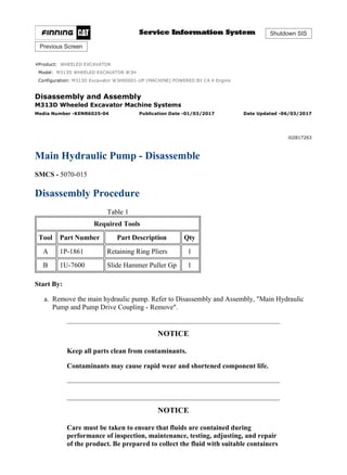
  • 6. Illustration 7 g01247258 7. Remove plug (25) and plug (26). 8. Remove cap (31), plug (30), O-ring seal (28), fitting (29), and pin (27). Illustration 8 g01247262 9. Remove pins (32), O-ring seals (33), O-ring seal (34), pin (35), and lever (36). Illustration 9 g01173603 10. Remove coupling (38), O-ring seal (39), bolts (37), and flange (40). 5/14(W)w 2020/4/26https://127.0.0.1/sisweb/sisweb/techdoc/techdoc_print_page.jsp?returnurl=/sisweb/sisw...
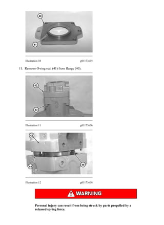
  • 7. Illustration 10 g01173605 11. Remove O-ring seal (41) from flange (40). Illustration 11 g01173606 Illustration 12 g01173608 Personal injury can result from being struck by parts propelled by a released spring force. 6/14(W)w 2020/4/26https://127.0.0.1/sisweb/sisweb/techdoc/techdoc_print_page.jsp?returnurl=/sisweb/sisw...
  • 8. Make sure to wear all necessary protective equipment. Follow the recommended procedure and use all recommended tooling to release the spring force. 12. Remove bolts (43) and pump adapter (42). Note: Seat adjusters (44) and (45) will come apart as pump adapter (42) is being removed. To prevent mixing of parts, slowly remove pump adapter (42). Illustration 13 g01173609 Illustration 14 g01173615 7/14(W)w 2020/4/26https://127.0.0.1/sisweb/sisweb/techdoc/techdoc_print_page.jsp?returnurl=/sisweb/sisw...
  • 9. Illustration 15 g01173616 13. Remove rods (46). 14. Mark the position of port plate (47) in relation to pump adapter (42) for assembly purposes. Remove port plate (47). 15. Remove spring (48) from seat adjuster (44). 16. Remove bushing (49), spring (50), and rod (51) from seat adjuster (45). Illustration 16 g01173619 17. Remove bearing (52), plugs (53), and the O-ring seals from pump adapter (42). 8/14(W)w 2020/4/26https://127.0.0.1/sisweb/sisweb/techdoc/techdoc_print_page.jsp?returnurl=/sisweb/sisw...
  • 10. Illustration 17 g01312794 18. Mark the position of the maximum angle stop screw (54) prior to removal from the piston pump (4). Remove maximum angle stop screw (54). Repeat for the opposite side of the piston pump in order to remove the minimum angle stop screw. Illustration 18 g01312797 19. Remove O-ring seal (57). Remove swashplate (56) and rotating assembly (55) as one piece. Illustration 19 g01312798 9/14(W)w 2020/4/26https://127.0.0.1/sisweb/sisweb/techdoc/techdoc_print_page.jsp?returnurl=/sisweb/sisw...
  • 11. Illustration 20 g01312799 Note: Mark barrel (63), pistons (58), and swashplate (56) for orientation. 20. The swashplate must be heated in order to melt the thread lock . Remove bolts (62) from swashplate (56). Note: Bolts (62) should be replaced with new bolts. 21. Remove retainers (60) and (61) from swashplate (56). 22. Remove rotating assembly (55) from swashplate (56). Illustration 21 g01312800 10/14(W)w 2020/4/26https://127.0.0.1/sisweb/sisweb/techdoc/techdoc_print_page.jsp?returnurl=/sisweb/sisw...
  • 12. Illustration 22 g01312801 23. Remove pistons (58) from barrel (63). 24. Remove retainer plate (59) from pistons (58). Illustration 23 g01312802 Illustration 24 g01312803 25. Remove retainer (64) from barrel (63). 26. Remove cup springs (65) and shims (66) from barrel (63). Note: Mark orientation of cup springs (65) and shims (66) for installation. 11/14(W)w 2020/4/26https://127.0.0.1/sisweb/sisweb/techdoc/techdoc_print_page.jsp?returnurl=/sisweb/sisw...
  • 13. Illustration 25 g01312804 27. Remove plugs (67) and slotted pins (68). Illustration 26 g01312805 28. Remove rods (69) from swashplate (57). Illustration 27 g01312807 29. Remove bearings (70 ) from piston pump (4). 12/14(W)w 2020/4/26https://127.0.0.1/sisweb/sisweb/techdoc/techdoc_print_page.jsp?returnurl=/sisweb/sisw...
  • 14. Illustration 28 g01312808 30. Remove outer races (71) from piston pump (4). Illustration 29 g01312809 31. Use Tooling (A) to remove retaining ring (72). 32. Use Tooling (B) to remove seal (73). 33. Use Tooling (A) to remove retaining ring (74). Illustration 30 g01312812 34. Remove shaft (75) from the piston pump. 13/14(W)w 2020/4/26https://127.0.0.1/sisweb/sisweb/techdoc/techdoc_print_page.jsp?returnurl=/sisweb/sisw...
  • 15. Illustration 31 g01312814 35. Use Tooling (A) to remove retaining ring (76) from shaft (74). 36. Remove bearing (77) from shaft (75). Use a suitable press to remove bearing (77). Copyright 1993 - 2020 Caterpillar Inc. All Rights Reserved. Private Network For SIS Licensees. Sun Apr 26 21:34:34 UTC+0800 2020 14/14(W)w 2020/4/26https://127.0.0.1/sisweb/sisweb/techdoc/techdoc_print_page.jsp?returnurl=/sisweb/sisw...
  • 16. Shutdown SIS Previous Screen Product: WHEELED EXCAVATOR Model: M313D WHEELED EXCAVATOR W3H Configuration: M313D Excavator W3H00001-UP (MACHINE) POWERED BY C4.4 Engine Disassembly and Assembly M313D Wheeled Excavator Machine Systems Media Number -KENR6025-04 Publication Date -01/03/2017 Date Updated -06/03/2017 i06804170 Main Hydraulic Pump - Assemble SMCS - 5070-016 Assembly Procedure Table 1 Required Tools Tool Part Number Part Description Qty A 1P-1861 Retaining Ring Pliers 1 C 464-4892(1) Test Ring 1 128-2746(2)(3) Test Ring 1 D 129-3873(1) Measuring Hub 1 129-3874(2)(3) Measuring Hub 1 E 128-2744 Measuring Bell 1 F - Vernier Height Gauge 1 G 1P-0510 Driver Gp 1 H 464-4893(1) Alignment Plug 1 128-2742(2) Alignment Plug 1 437-5508(3) Alignment Plug 1 J - Loctite 242 - (1) Use for 95 cc pumps. (2) Use for 130 cc pumps. (3) Use for 145 cc pumps. 1/18(W)w 2020/4/26https://127.0.0.1/sisweb/sisweb/techdoc/techdoc_print_page.jsp?returnurl=/sisweb/sisw...
  • 17. NOTICE Keep all parts clean from contaminants. Contaminants may cause rapid wear and shortened component life. Illustration 1 g01312814 1. Use Tooling (A) to install bearing (77) to shaft (75). Raise the temperature of bearing (77). Install retaining ring (76) to shaft (75). Illustration 2 g01313371 2. Install shaft (75) into the piston pump. 2/18(W)w 2020/4/26https://127.0.0.1/sisweb/sisweb/techdoc/techdoc_print_page.jsp?returnurl=/sisweb/sisw...
  • 18. Illustration 3 g01312809 3. Use Tooling (A) to install retaining ring (74). 4. Use Tooling (G) to install seal (73). 5. Use Tooling (A) to install retaining ring (72). Illustration 4 g01312808 6. Install outer races (71) to piston pump (4). Illustration 5 g01312805 7. Install rods (69) to swashplate (57). 3/18(W)w 2020/4/26https://127.0.0.1/sisweb/sisweb/techdoc/techdoc_print_page.jsp?returnurl=/sisweb/sisw...
  • 19. Illustration 6 g01313372 Illustration 7 g01313374 8. Install bearings (70) to swashplate (56). Install a rubber band to each of bearings (70). The rubber band will hold bearings (70) to swashplate (56). 9. Carefully install swashplate (56) to piston pump (4). Illustration 8 g01313375 10. Cut the rubber band on swashplate (56). 4/18(W)w 2020/4/26https://127.0.0.1/sisweb/sisweb/techdoc/techdoc_print_page.jsp?returnurl=/sisweb/sisw...
  • 20. Illustration 9 g01312804 Note: Rods (68) must engage slotted pins (68). 11. Install plugs (67) and slotted pins (68). Illustration 10 g01312794 12. Install the maximum angle stop screw (54). Repeat for the opposite side of piston pump (4) to install the minimum angle stop screw. Illustration 11 g01173661 13. Place port plate (47) on a surface plate. 5/18(W)w 2020/4/26https://127.0.0.1/sisweb/sisweb/techdoc/techdoc_print_page.jsp?returnurl=/sisweb/sisw...
  • 21. Illustration 12 g01173662 14. Install Tooling (H) to port plate (47). Illustration 13 g01313379 15. Install barrel (63) onto Tooling (H) and port plate (47). Illustration 14 g01313380 16. Install Tooling (C) to retainer (64). Shims and springs must be removed from retainer (64). 6/18(W)w 2020/4/26https://127.0.0.1/sisweb/sisweb/techdoc/techdoc_print_page.jsp?returnurl=/sisweb/sisw...
  • 22. Illustration 15 g01313382 17. Install retainer (64) to barrel (63). Illustration 16 g01313384 18. Install retainer plate (59) to retainer (64). Illustration 17 g00903603 19. Bolt Tooling (D) to Tooling (E). 7/18(W)w 2020/4/26https://127.0.0.1/sisweb/sisweb/techdoc/techdoc_print_page.jsp?returnurl=/sisweb/sisw...
  • 23. Illustration 18 g01313386 20. Install assembled Tooling (D) and Tooling (E) into the splined bores of retainer (64). Make sure that Tooling is properly seated. Illustration 19 g01313387 21. Record the dimension that is stamped on the side of Tooling (E). This dimension is the distance from the top of retainer plate (59) to the top of Tooling (E). This dimension is called Dimension (W). Illustration 20 g00903619 8/18(W)w 2020/4/26https://127.0.0.1/sisweb/sisweb/techdoc/techdoc_print_page.jsp?returnurl=/sisweb/sisw...
  • 24. Thank you very much for your reading. Please Click Here. Then Get COMPLETE MANUAL. NO WAITING NOTE: If there is no response to click on the link above, please download the PDF document first and then click on it.
  • 25. 22. Use Tooling (F) to measure the distance from the top of the surface plate to the top of Tooling (E). Record this dimension. Call this Dimension (X). 23. Use the following calculation: Dimension (X) - Dimension (W) = Dimension (Y). 24. Dimension (Y) is the correct lift-off limitation without shim (66). Note: This is the correct lift-off limitation for the 95 cc main hydraulic pump. 122.65 + 0.0 − 0.200 mm (4.8287 + 0.00 − 0.0078 inch) Call this Dimension (Z). Note: This is the correct lift-off limitation for the 130 cc and 145 cc main hydraulic pump. 136.95 + 0.0 − 0.200 mm (5.3917 + 0.00 − 0.0078 inch) Call this Dimension (Z). 25. Use the following calculation: Dimension (Z) - Dimension (Y) = Thickness of shim (66). Note: Shim (66) is available in several thicknesses. Select the correct thickness of shim (66) to obtain the correct lift-off limitation. Only one shim (66) should be used. Illustration 21 g01312802 Illustration 22 g01312803 26. Install cup springs (65) and shim (66) to barrel (63). 27. Install retainer (64) to barrel (63). 9/18(W)w 2020/4/26https://127.0.0.1/sisweb/sisweb/techdoc/techdoc_print_page.jsp?returnurl=/sisweb/sisw...
  • 26. Illustration 23 g01312801 28. Install pistons (58) to retainer plate (59). Illustration 24 g01312800 29. Install retainer plate (59) with pistons (58) to barrel (63). Illustration 25 g01313388 10/18(W)w 2020/4/26https://127.0.0.1/sisweb/sisweb/techdoc/techdoc_print_page.jsp?returnurl=/sisweb/sisw...
  • 27. Illustration 26 g01313391 Illustration 27 g01313392 30. Install rotating assembly (55) into piston pump (4). 31. Install retainers (61) and bolts (62). Use Tooling (J) on bolts (62). Note: Bolts (62) should be replaced with new bolts. 32. Install O-ring seal (57) to piston pump (4). Illustration 28 g01173619 33. Install bearing (52), plugs (53), and the O-ring seals in pump adapter (42). 11/18(W)w 2020/4/26https://127.0.0.1/sisweb/sisweb/techdoc/techdoc_print_page.jsp?returnurl=/sisweb/sisw...