CATHODE
RAY
OSCILLOSCOPE
PRESENTED BY-
 SUSHIL KUMAR SINGH
 LAKSHMI
 SIDDHARTH YADAV
 MRIGANKA BHATTACHARJEE
 KRISHNA KUMAR BHARGAV
(dedicated to Almighty god)
2
UNDER THE GUIDENCE OF –
UPMA DAS
16 May, 2017
CONTENTS-
 INTRODUCTION
 BLOCK DIAGRAM OF CRO
 CALCULATION
 CATHODE RAY TUBE
 ADVANTAGES / DISADVANTAGES
 APPLICATIONS
3 16 May, 2017
INTRODUCTION-
CRO is an electronic device containing a cathode ray tube(CRT)
that generates an electron beam that is used to produce visible
patterns, graphs on a phosphorescent screen.
HISTORY :
The first CRO was developed by German
physicist Ferdinand Brawn in 1897.
CRO is a common laboratory instrument that
provides accurate time and amplitude Measur-
ement of voltage signal over a wide range of
frequency .
4
16 May, 2017
FIG:EXTERNAL VIEW OF CRO
5 16 May, 2017
TYPES OF CRO-
 ANALOG CRO :
It is the simplest and earliest type of oscilloscope comprises of a
vertical amplifier, a cathode ray tube, time base, a power supply
and a horizontal amplifier. These are commonly known as analog
CRO.
 DIGITAL CRO :
It is a complex electronic device composed of various software
and electronic hardware modules that work together to capture,
process, display and store data that represents the signals of
interest of operator.
6 16 May, 2017
BASIC BLOCKS OF CRO-
7 16 May, 2017
BLOCK DISCRIPTION-
 VERTICAL AMPLIFIER:
The input signals are amplified by vertical amplifier to
make the waveform compatible for operation.
We can obtain the sensitivity of oscilloscope by vertical
amplifier. The sensitivity of an oscilloscope (in V/div.) is
directly proportional to the gain of the vertical amplifier.
 TRIGGER CIRCUIT:
The signals which are used to activate the trigger circuit are
converted to trigger pulses for the precision sweep operation
whose amplitude is uniform. Hence input signal can be
synchronized.
8 16 May, 2017
 TIME-BASE GENERATOR:
The Time-base circuit uses a Transistor, which is used to
produce the ramp voltage. The ramp voltage produced by
this circuit is required to deflect the beam in horizontal
section.
9
FIG:-Sweep circuit and ramp voltage diaram 16 May, 2017
10 16 May, 2017
 HORIZONTAL AMPLIFIER:
The ramp voltage produced by the time base
generator is amplified by the horizontal
amplifier ,before it applied to horizontal
deflection plates.
 Delay Line:
The Delay line retards the arrival of the
amplified waveform obtained from vertical
amplifier to reach to the vertical plates.
BASIC CRO CIRCUIT-
11 16 May, 2017
12 16 May, 2017
 BLANKING CIRCUIT:
While retracing the horizontal line from left to right, the
movement of spot will appear as a thin and dim line. Ideally it
should be invisible, so to make it invisible a circuit provided
known as blanking circuit.
 CALIBRATION OSCILLATOR:
Some laboratory oscilloscopes having internally generated input
voltage of known voltage which is provided by this oscillator
circuit.
CALCULATION
FORMULA1
Voltage(V)= (no.of division) X (*ch1).
Peak voltage=2V
Where:*ch1 is the VOLTAGE/DEVISION
Value Of the waveform.
FORMULA2
Time period= (no.of division) X (TB).
Where: TB is the TIME/DEVISION
 Volt=1*5 =5volt.
 Time =(.2 ms)*2 =(.4 ms)
frequency=1/(.4ms)
=2.5 kHZ13
16 May, 2017
CATHODE RAY TUBE -
 It consist of THREE major portion-
14 16 May, 2017
ELECTRON GUN:
Electron gun tube is the source of electron which emits electron with very high ENERGY
& acceleration/
15
16 May, 2017
ANODE PLATES(focusing & accelerating)
++ ++ ++++ ++
---------------------------------------------
++ ++ ++ ++
 Function of Anode plates is to give a ACCELERATION and a
particular direction to e’ beam.
 The supply voltage is very high (1500)v.
16 16 May, 2017
17
DEFLECTING PLATES
There are two types of deflecting plate-
1. VERTICAL DEFLECTING PLATE- resposible for
y axis portion of graph.
1. HORIZONTAL DEFLECTING PLATE- resposible
x axis portion of graph.
1.
1.
2. Vertical charge plate 2.Horizontal charge plate 18
. 16 May, 2017
19 16 May, 2017
Animation of Cathode ray
tube:
20 16 May, 2017
FLUORESCENT SCREEN:
 Fluorescent screen is a transparent screen
Coated with Fluorescent material
( phosphorus ).
 Phosporous emit low frequency
(visible spectra) light when it
absorb the kinetic energy of
electron.
21
16 May, 2017
SUMARRY OF CRT
22
ADVANTAGES OF CRO-
 RESOLUTION AND ASPECT RATIO-
IT OPERATES AT ANY RESOLUTION,GEOMETRY AND ASPECT
RATIO WITHOUT THE NEED FOR RESCALING THE IMAGE.
 HIGHEST RESOLUTIONS-
IT RUNS AT THE HIGHEST PIXEL RESOLUTIONS GENERALLY
AVAILABLE.
 HIGH CONTRAST LEVEL-
IT PRODUCES HIGHEST CONTRAST LEVEL SUITABLE FOR USE
EVEN IN DIMLY LIGHT OR DARK ENVIRONMENT.
 FAST RESPONSE-
CRT GIVES FAST RESPONSE TO THE SIGNAL SO IT IS BEST FOR
A RAPIDLY MOVING AND CHANGING WAVE.
23 16 May, 2017
DISADVANTAGES OF CRO-
 VERY SENSITIVE-
SENSITIVE DEVICE AND REQUIRES COMPLETE
ISOLATION FROM NOISE PRONE RESOURCES.
 PHYSICAL-
THEY ARE VERY LARGE ,HEAVY AND BULKY.THEY CONSUME A LOT OF ELECTRICITY
AND PRODUCE A LOT OF HEAT.
 BRIGHTNESS-
RELATIVELY BRIGHT BUT NOT AS BRIGHT AS LCD’S. ITS NOT SUITABLE FOR VERY
BRIGHTLY LIT ENVIRONMENT.
 CONTROL TERMINALS-
THERE ARE LOTS OF CONTROL TERMINALS OVER THE CONTROL PANEL THAT
LEADS TO A GREATER COMPLEXITY OF THE DEVICE MAKING IT DIFFICULT TO USE.
24 16 May, 2017
USE & APPLICATION OF CRO
 TO SEE THE WAVEFORMS- we can see the waveform of
input signal with the help of CRO.
 FREQUENCY MEASUREMENT-Using a CRO we can
determine the frequency of the unknown waveforms.
Mathematically: (y axis value X CH*)=T(time period)
So, Frequency=1T.
 VOLTAGE MEASUREMENT- Y AXIS of waveform give the
amplitude value of input signal in volt.
25 16 May, 2017
 IT IS USE IN DESINE OF NEW CIRCUIT- CRO is strictly
advise to see the exact output of new develop circuit. And to
check the defective components in new circuit.
 IT IS BASICALLY USE IN SCIENTFIC AND ENGINEERING
APPLICATIONS.
26 16 May, 2017
REFRENCES:
 AK SAWHNEY-Electronic instrumentation and
measurement
 H.S KALSI-Electronic instrumentation and
measurement
 DAVID A.BELL-Electronic instrumentation
27 16 May, 2017
28 16 May, 2017
29 16 May, 2017

More Related Content

PPTX
Cathode Ray Oscilloscope CRO
PPTX
Cro cathode ray oscilloscope working and applications
PPT
Unit 1 cro ppt
PPTX
Presentation on cro
PPTX
cathode ray oscilloscope
PPT
Digital storage ocilloscope
PPTX
Q meter ppt
PPTX
Measurement of resistance
Cathode Ray Oscilloscope CRO
Cro cathode ray oscilloscope working and applications
Unit 1 cro ppt
Presentation on cro
cathode ray oscilloscope
Digital storage ocilloscope
Q meter ppt
Measurement of resistance

What's hot (20)

PPTX
Amplifier
PPTX
Op amp(operational amplifier)
PPSX
PPTX
Transformer construction,types and working
PPTX
Basics of amplifier.ppt
PPTX
Transistor , NPN & PNP Transistor
PPTX
PMMC Instruments
PDF
Ammeter and voltmeter
PPTX
Transistor
PPTX
POTENTIOMETER
PPTX
Oscillators
PPTX
Transducers
PPTX
Transducers
PPTX
Function generator
PPTX
Transistor biasing
PPTX
Ammeter, voltmeter, wattmeter, power factor meter
PPT
Transformer ppt download
PPTX
Inductive Transducer
PPTX
Unit 3
PPTX
Small signal analysis of bjt amplifiers
Amplifier
Op amp(operational amplifier)
Transformer construction,types and working
Basics of amplifier.ppt
Transistor , NPN & PNP Transistor
PMMC Instruments
Ammeter and voltmeter
Transistor
POTENTIOMETER
Oscillators
Transducers
Transducers
Function generator
Transistor biasing
Ammeter, voltmeter, wattmeter, power factor meter
Transformer ppt download
Inductive Transducer
Unit 3
Small signal analysis of bjt amplifiers
Ad

Similar to CATHODE RAY OSCILLOSCOPE (CRO) (20)

PPTX
CRO,DSO,multimeter.pptxffffffffffffffffffffffffffffffffffffffffffffffff
PPT
Cathode-ray-Oscilloscopendjknddnilndoid.ppt
PPT
Cathode ray oscilloscope for engineering .ppt
PPT
emi 3rd ye 2semhapter-14 instrunments.ppt
PPT
Chapter-14 (1) measurementys and instruments.ppt
PPT
PE&I Chapter-14. ...
PPTX
Cathode Ray Oscilloscope
PPTX
Cathode ray oscilloscope bsc notes vi sem
PPT
CRO and FG.ppt
PPT
cro oscilloscope for physics classes and students.ppt
PPTX
Cro (emmi) (1)
PPTX
Rasmita chhatoi presentation.pptx
PPTX
Cathode Ray Oscilloscope CRO & Digital Oscilloscope 'S WORKING
PPTX
157929707-Presentation-on-Cro.pptx
PPTX
Emi unit ii ppt
PPTX
CATHODE RAY OSCILLOSCOPE-1.pptx ppt of cathode
PPT
Cro (cathod ray oscilloscope)
PPT
(19) electronic instruments 1
PPTX
Description of Cathode ray oscilloscope.pptx
PPT
Cathode Ray Oscilloscope
CRO,DSO,multimeter.pptxffffffffffffffffffffffffffffffffffffffffffffffff
Cathode-ray-Oscilloscopendjknddnilndoid.ppt
Cathode ray oscilloscope for engineering .ppt
emi 3rd ye 2semhapter-14 instrunments.ppt
Chapter-14 (1) measurementys and instruments.ppt
PE&I Chapter-14. ...
Cathode Ray Oscilloscope
Cathode ray oscilloscope bsc notes vi sem
CRO and FG.ppt
cro oscilloscope for physics classes and students.ppt
Cro (emmi) (1)
Rasmita chhatoi presentation.pptx
Cathode Ray Oscilloscope CRO & Digital Oscilloscope 'S WORKING
157929707-Presentation-on-Cro.pptx
Emi unit ii ppt
CATHODE RAY OSCILLOSCOPE-1.pptx ppt of cathode
Cro (cathod ray oscilloscope)
(19) electronic instruments 1
Description of Cathode ray oscilloscope.pptx
Cathode Ray Oscilloscope
Ad

Recently uploaded (20)

PPTX
"Array and Linked List in Data Structures with Types, Operations, Implementat...
PDF
Introduction to Power System StabilityPS
PDF
Exploratory_Data_Analysis_Fundamentals.pdf
PDF
distributed database system" (DDBS) is often used to refer to both the distri...
PDF
Design of Material Handling Equipment Lecture Note
PPTX
PRASUNET_20240614003_231416_0000[1].pptx
PDF
Beginners-Guide-to-Artificial-Intelligence.pdf
PPTX
Management Information system : MIS-e-Business Systems.pptx
PDF
VSL-Strand-Post-tensioning-Systems-Technical-Catalogue_2019-01.pdf
PPTX
Graph Data Structures with Types, Traversals, Connectivity, and Real-Life App...
DOC
T Pandian CV Madurai pandi kokkaf illaya
PPTX
ASME PCC-02 TRAINING -DESKTOP-NLE5HNP.pptx
PDF
Unit I -OPERATING SYSTEMS_SRM_KATTANKULATHUR.pptx.pdf
PDF
Influence of Green Infrastructure on Residents’ Endorsement of the New Ecolog...
PDF
August 2025 - Top 10 Read Articles in Network Security & Its Applications
PDF
Computer organization and architecuture Digital Notes....pdf
PPTX
ai_satellite_crop_management_20250815030350.pptx
PPTX
mechattonicsand iotwith sensor and actuator
PDF
MLpara ingenieira CIVIL, meca Y AMBIENTAL
PPTX
Petroleum Refining & Petrochemicals.pptx
"Array and Linked List in Data Structures with Types, Operations, Implementat...
Introduction to Power System StabilityPS
Exploratory_Data_Analysis_Fundamentals.pdf
distributed database system" (DDBS) is often used to refer to both the distri...
Design of Material Handling Equipment Lecture Note
PRASUNET_20240614003_231416_0000[1].pptx
Beginners-Guide-to-Artificial-Intelligence.pdf
Management Information system : MIS-e-Business Systems.pptx
VSL-Strand-Post-tensioning-Systems-Technical-Catalogue_2019-01.pdf
Graph Data Structures with Types, Traversals, Connectivity, and Real-Life App...
T Pandian CV Madurai pandi kokkaf illaya
ASME PCC-02 TRAINING -DESKTOP-NLE5HNP.pptx
Unit I -OPERATING SYSTEMS_SRM_KATTANKULATHUR.pptx.pdf
Influence of Green Infrastructure on Residents’ Endorsement of the New Ecolog...
August 2025 - Top 10 Read Articles in Network Security & Its Applications
Computer organization and architecuture Digital Notes....pdf
ai_satellite_crop_management_20250815030350.pptx
mechattonicsand iotwith sensor and actuator
MLpara ingenieira CIVIL, meca Y AMBIENTAL
Petroleum Refining & Petrochemicals.pptx

CATHODE RAY OSCILLOSCOPE (CRO)

  • 2. PRESENTED BY-  SUSHIL KUMAR SINGH  LAKSHMI  SIDDHARTH YADAV  MRIGANKA BHATTACHARJEE  KRISHNA KUMAR BHARGAV (dedicated to Almighty god) 2 UNDER THE GUIDENCE OF – UPMA DAS 16 May, 2017
  • 3. CONTENTS-  INTRODUCTION  BLOCK DIAGRAM OF CRO  CALCULATION  CATHODE RAY TUBE  ADVANTAGES / DISADVANTAGES  APPLICATIONS 3 16 May, 2017
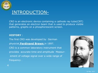
  • 4. INTRODUCTION- CRO is an electronic device containing a cathode ray tube(CRT) that generates an electron beam that is used to produce visible patterns, graphs on a phosphorescent screen. HISTORY : The first CRO was developed by German physicist Ferdinand Brawn in 1897. CRO is a common laboratory instrument that provides accurate time and amplitude Measur- ement of voltage signal over a wide range of frequency . 4 16 May, 2017
  • 5. FIG:EXTERNAL VIEW OF CRO 5 16 May, 2017
  • 6. TYPES OF CRO-  ANALOG CRO : It is the simplest and earliest type of oscilloscope comprises of a vertical amplifier, a cathode ray tube, time base, a power supply and a horizontal amplifier. These are commonly known as analog CRO.  DIGITAL CRO : It is a complex electronic device composed of various software and electronic hardware modules that work together to capture, process, display and store data that represents the signals of interest of operator. 6 16 May, 2017
  • 7. BASIC BLOCKS OF CRO- 7 16 May, 2017
  • 8. BLOCK DISCRIPTION-  VERTICAL AMPLIFIER: The input signals are amplified by vertical amplifier to make the waveform compatible for operation. We can obtain the sensitivity of oscilloscope by vertical amplifier. The sensitivity of an oscilloscope (in V/div.) is directly proportional to the gain of the vertical amplifier.  TRIGGER CIRCUIT: The signals which are used to activate the trigger circuit are converted to trigger pulses for the precision sweep operation whose amplitude is uniform. Hence input signal can be synchronized. 8 16 May, 2017
  • 9.  TIME-BASE GENERATOR: The Time-base circuit uses a Transistor, which is used to produce the ramp voltage. The ramp voltage produced by this circuit is required to deflect the beam in horizontal section. 9 FIG:-Sweep circuit and ramp voltage diaram 16 May, 2017
  • 10. 10 16 May, 2017  HORIZONTAL AMPLIFIER: The ramp voltage produced by the time base generator is amplified by the horizontal amplifier ,before it applied to horizontal deflection plates.  Delay Line: The Delay line retards the arrival of the amplified waveform obtained from vertical amplifier to reach to the vertical plates.
  • 11. BASIC CRO CIRCUIT- 11 16 May, 2017
  • 12. 12 16 May, 2017  BLANKING CIRCUIT: While retracing the horizontal line from left to right, the movement of spot will appear as a thin and dim line. Ideally it should be invisible, so to make it invisible a circuit provided known as blanking circuit.  CALIBRATION OSCILLATOR: Some laboratory oscilloscopes having internally generated input voltage of known voltage which is provided by this oscillator circuit.
  • 13. CALCULATION FORMULA1 Voltage(V)= (no.of division) X (*ch1). Peak voltage=2V Where:*ch1 is the VOLTAGE/DEVISION Value Of the waveform. FORMULA2 Time period= (no.of division) X (TB). Where: TB is the TIME/DEVISION  Volt=1*5 =5volt.  Time =(.2 ms)*2 =(.4 ms) frequency=1/(.4ms) =2.5 kHZ13 16 May, 2017
  • 14. CATHODE RAY TUBE -  It consist of THREE major portion- 14 16 May, 2017
  • 15. ELECTRON GUN: Electron gun tube is the source of electron which emits electron with very high ENERGY & acceleration/ 15 16 May, 2017
  • 16. ANODE PLATES(focusing & accelerating) ++ ++ ++++ ++ --------------------------------------------- ++ ++ ++ ++  Function of Anode plates is to give a ACCELERATION and a particular direction to e’ beam.  The supply voltage is very high (1500)v. 16 16 May, 2017
  • 17. 17
  • 18. DEFLECTING PLATES There are two types of deflecting plate- 1. VERTICAL DEFLECTING PLATE- resposible for y axis portion of graph. 1. HORIZONTAL DEFLECTING PLATE- resposible x axis portion of graph. 1. 1. 2. Vertical charge plate 2.Horizontal charge plate 18 . 16 May, 2017
  • 19. 19 16 May, 2017
  • 20. Animation of Cathode ray tube: 20 16 May, 2017
  • 21. FLUORESCENT SCREEN:  Fluorescent screen is a transparent screen Coated with Fluorescent material ( phosphorus ).  Phosporous emit low frequency (visible spectra) light when it absorb the kinetic energy of electron. 21 16 May, 2017
  • 23. ADVANTAGES OF CRO-  RESOLUTION AND ASPECT RATIO- IT OPERATES AT ANY RESOLUTION,GEOMETRY AND ASPECT RATIO WITHOUT THE NEED FOR RESCALING THE IMAGE.  HIGHEST RESOLUTIONS- IT RUNS AT THE HIGHEST PIXEL RESOLUTIONS GENERALLY AVAILABLE.  HIGH CONTRAST LEVEL- IT PRODUCES HIGHEST CONTRAST LEVEL SUITABLE FOR USE EVEN IN DIMLY LIGHT OR DARK ENVIRONMENT.  FAST RESPONSE- CRT GIVES FAST RESPONSE TO THE SIGNAL SO IT IS BEST FOR A RAPIDLY MOVING AND CHANGING WAVE. 23 16 May, 2017
  • 24. DISADVANTAGES OF CRO-  VERY SENSITIVE- SENSITIVE DEVICE AND REQUIRES COMPLETE ISOLATION FROM NOISE PRONE RESOURCES.  PHYSICAL- THEY ARE VERY LARGE ,HEAVY AND BULKY.THEY CONSUME A LOT OF ELECTRICITY AND PRODUCE A LOT OF HEAT.  BRIGHTNESS- RELATIVELY BRIGHT BUT NOT AS BRIGHT AS LCD’S. ITS NOT SUITABLE FOR VERY BRIGHTLY LIT ENVIRONMENT.  CONTROL TERMINALS- THERE ARE LOTS OF CONTROL TERMINALS OVER THE CONTROL PANEL THAT LEADS TO A GREATER COMPLEXITY OF THE DEVICE MAKING IT DIFFICULT TO USE. 24 16 May, 2017
  • 25. USE & APPLICATION OF CRO  TO SEE THE WAVEFORMS- we can see the waveform of input signal with the help of CRO.  FREQUENCY MEASUREMENT-Using a CRO we can determine the frequency of the unknown waveforms. Mathematically: (y axis value X CH*)=T(time period) So, Frequency=1T.  VOLTAGE MEASUREMENT- Y AXIS of waveform give the amplitude value of input signal in volt. 25 16 May, 2017
  • 26.  IT IS USE IN DESINE OF NEW CIRCUIT- CRO is strictly advise to see the exact output of new develop circuit. And to check the defective components in new circuit.  IT IS BASICALLY USE IN SCIENTFIC AND ENGINEERING APPLICATIONS. 26 16 May, 2017
  • 27. REFRENCES:  AK SAWHNEY-Electronic instrumentation and measurement  H.S KALSI-Electronic instrumentation and measurement  DAVID A.BELL-Electronic instrumentation 27 16 May, 2017
  • 28. 28 16 May, 2017
  • 29. 29 16 May, 2017