The document discusses modular programming concepts in assembly language. It explains that large programming problems can be broken down into modules that are tested individually and then linked together. It outlines some issues that must be resolved for successful linking, such as data access permissions and external labels. The directives PUBLIC and EXTRN are described as ways to declare data, procedures, and labels that need to be accessed externally or are defined externally. The document provides examples of how to use these directives and assemble/link multiple modules into a single program.
The document discusses the architecture of the 8086 microprocessor. It describes the 8086 as a 16-bit processor that can access external memory using a 20-bit address bus. The 8086 uses memory segmentation to map the larger 20-bit physical addresses to the smaller 16-bit registers. Each segment is defined by a base address stored in a 16-bit segment register. The 20-bit physical address is calculated by combining the segment register value and offset. The document provides details on the various memory segments and addressing modes supported by the 8086 architecture.
The document provides information on advanced assembly language procedures. It discusses the PROC, ADDR, INVOKE and PROTO directives which are used to declare and call procedures. The PROC directive declares a procedure with optional parameters, while INVOKE simplifies procedure calls by passing parameters in a single statement. PROTO creates a procedure prototype. ADDR returns the address of a variable. Stack frames and how parameters and local variables are accessed on the stack are explained. Recursive procedures and how they use stack frames are covered, with examples to calculate a sum and factorial recursively. Finally, the document discusses creating multimodule programs by dividing code across multiple source files that are assembled and linked together.
This document describes the basic structure of an assembly language program and provides an example of adding two 16-bit binary coded decimal (BCD) numbers in assembly language. The program structure includes defining data and code segments. It shows how to declare variables in the data segment, move values to registers, perform addition with decimal adjust, and store the results. The example adds the two BCD numbers 9384 and 1845, storing the carry of 1 in the CARRY variable and the sum of 11229 in the SUM variable.
The document provides information about assembly language, including definitions, instruction formats, and the process of assembling, linking and executing an assembly language program. It defines assembly language as a language that uses symbols and letters instead of binary to represent instructions and storage locations. It also describes common instruction types like data transfer, arithmetic, logic and shift instructions. Finally, it outlines the steps to create an assembly program, which includes writing source code, assembling it, linking the object files, and executing the final executable.
Microprocessor 8086 instruction descriptionDheeraj Suri
The document discusses assembler programs and emulators for the 8086 microprocessor. It provides the following information:
- An assembler program translates assembly language mnemonics into binary machine codes. It performs two passes through the source code to calculate offsets and produce the final binary output.
- An emulator is a combination of hardware and software that allows programs to run by downloading object code into RAM and simulating the microprocessor. Emulators like EMU8086 allow examining and modifying registers and memory.
- Instructions like AAA, AAS, AAM, and AAD are used to adjust results of numeric operations involving ASCII-encoded digits to produce the proper unpacked Binary Coded Decimal values.
This presentation covers very basics of assembly language with some computer organization concept. I took this session as part of on going series on assembly at NULL Hyderabad meets. PART II will cover instruction sets and more in detail.
The document provides information about the instruction sets of the 8086 microprocessor. It defines what an instruction set is and describes the different instruction formats used by the 8086. The main types of 8086 instructions are then outlined, including data transfer instructions, arithmetic instructions, bit manipulation instructions, branch instructions, and others. Specific instructions like MOV, ADD, SUB, and MUL are explained through examples of their syntax and operation.
This document provides an introduction to assembly language programming. It describes the basic components of a computer including the central processing unit and its registers. The CPU registers discussed include general purpose registers like the accumulator, base, counter, and data registers. Memory segmentation and the flag register are also explained. Pointer and index registers like the stack pointer, base pointer, and source/destination indexes are defined. The document was prepared by the Department of Computer Science and Engineering at United International University.
Chapter 3 INSTRUCTION SET AND ASSEMBLY LANGUAGE PROGRAMMINGFrankie Jones
3.1 UNDERSTANDING INSTRUCTION SET AND ASSEMBLY LANGUAGE
3.1.1 Define instruction set,machine and assembly language
3.1.2 Describe features and architectures of various type of microprocessor
3.1.3 Describe the Addressing Modes
3.2 APPLY ASSEMBLY LANGUAGE
3.2.1 Write simple program in assembly language
3.2.2 Tool in analyzing and debugging assembly language program
The document discusses the instruction set of the 8086 microprocessor. It describes that the 8086 has over 20,000 instructions that are classified into several categories like data transfer, arithmetic, bit manipulation, program execution transfer, and string instructions. Under each category, it provides details about specific instructions like MOV, ADD, AND, CALL, etc. and explains their functionality and operand usage.
The document describes the instruction formats of the 8086 microprocessor. It has 1-6 byte instruction sizes with an opcode field in the first byte. The second byte contains mode, register, and register/memory fields that specify operands. It defines register codes and explains how the mode, register, and register/memory fields are used to determine operands and effective addresses. Examples show how to encode instructions like MOV, SUB, and ADD using the instruction format. Input/output instructions like IN and OUT are also described, indicating how port numbers can be immediate values or specified with the DX register.
The document discusses several topics related to computer architecture and assembly language programming:
1. It describes the von Neumann architecture model and key components like the ALU, control unit, and memory.
2. It summarizes Moore's Law and how increasing transistor density has allowed for higher performance chips over time.
3. It provides an overview of some early Intel processors like the 8086 and techniques used to increase processor speed like pipelining.
4. It includes brief explanations of common assembly language concepts like registers, memory addressing, and arithmetic and logical instructions.
The document discusses assembly language programming concepts including shift, rotate, flag control, compare, and jump instructions. It provides examples and problems to explain the usage and effects of various instructions. Key points include:
- Shift instructions move bits within a register or memory location based on a count. Common instructions are SHR, SAR, SHL, ROL, ROR.
- Flag control instructions modify status flags. Common ones are LAHF, SAHF, CLC, STC.
- Compare instruction CMP performs subtraction without affecting operands and updates flags.
- Jump instructions conditionally transfer control based on status flag values like JO, JB, JE, JL.
Pro
This document provides an introduction to 8086 assembly language programming. It discusses program statements, data storage directives, defining and naming data, data transfer instructions, and the basic structure of an assembly language program, including segments for code, data, and stack. Pseudo-operations and directives are used to define variables and reserve memory. Data types like bytes, words, and doublewords are stored in reverse order in memory.
The document discusses various methods of writing and assembling a simple "Hello World" program in x86 Assembly using NASM, including:
1) Using Linux system calls to write to stdout and exit
2) Using Win32 system calls and avoiding interrupts
3) Using C library functions like printf and linking with gcc for cross-platform compatibility
The document discusses various arithmetic instructions in assembly language including INC, DEC, ADD, SUB, MUL, DIV.
It explains the syntax and usage of each instruction, showing how they can increment, decrement, add, subtract, multiply or divide operands in registers or memory. Examples are given to illustrate how to perform basic arithmetic operations like addition and multiplication of numbers entered by the user.
This document provides an introduction to 8086 assembly language programming. It discusses machine code and assembly language, compilers and assemblers, general purpose registers, simple commands, number formats, jumps, labels, logical and shift instructions, and instructions that affect memory. The key points are that assembly language provides a lower-level programming interface than high-level languages, manages memory and registers directly, and uses mnemonics that are assembled into machine code.
The document discusses various instruction types and data transfer instructions in the 8086 microprocessor. It provides details on different categories of instructions like data transfer, arithmetic, logical, string, and program flow instructions. Examples are given for common instructions like MOV, ADD, AND, SHIFT, CALL, RET. Addressing modes, operand types, flags affected are explained for many fundamental instructions.
The document discusses various types of operands and addressing modes in x86 assembly language. It describes three basic operand types: immediate, register, and memory. It covers different addressing modes for accessing memory operands, including direct, register indirect, indexed, based, and based-indexed addressing. Examples are provided to illustrate how to copy a string and sum elements of an array using these addressing modes. Key registers used for 32-bit and 16-bit memory addressing are also outlined.
This document discusses different types of addressing modes used in computers. It defines addressing mode as the way operands are chosen during program execution based on the addressing technique specified in an instruction. There are several addressing modes described, including implied, immediate, register, register indirect, auto-increment/decrement, direct, indirect, relative, indexed, and base register modes. Examples and a numerical example are provided to illustrate the different addressing modes.
The document discusses various aspects of assembler design and implementation including:
1) The basic functions of an assembler in translating mnemonic codes to machine language and assigning addresses to symbols.
2) Machine-dependent features like different instruction formats and addressing modes, and how programs are relocated during assembly.
3) Machine-independent features including the use of literals, symbol-defining statements, expressions, program blocks, and linking of control sections between programs.
This document discusses different addressing modes used in the 8051 microcontroller architecture, including immediate, direct, register, and indirect addressing modes. Immediate addressing encodes the data as part of the instruction itself. Direct addressing retrieves data directly from another memory location. Register addressing uses register names as part of the opcode. Indirect addressing provides flexibility by allowing the contents of a register to specify the memory location of the operand.
Ec 252 ec-252-l10-instruction sets and addressing modesbhshmuec
This document discusses computer architecture and microprocessors. It covers topics such as instruction sets, instruction formats, addressing modes, and types of instructions. The key points are:
- An instruction set is the complete collection of instructions understood by a CPU, usually represented in both machine code and assembly code.
- Instructions contain operation codes and references to operands and results. Common addressing modes include immediate, direct, indirect, register, and displacement addressing.
- Instruction types include data processing, data storage/movement, and program flow control. Design decisions include the instruction repertoire and number of operand addresses.
- Common arithmetic operations are addition, subtraction, multiplication and division of signed integers and floating point numbers. Addressing modes
Washing machine is the machine used to wash the various types of clothes without applying any physical efforts. With washing machine you don’t have to rub the clothes with hand or squeeze them to remove the water from them. The washing machine is also called as clothes washer or simply the washer. The washing machine enables you to wash your clothes automatically without having to supervise its operation. All you have to do is put the clothes in the machine and select the wash mode. The washing machine automatically takes in the amount of water and detergent required and it also automatically sets the timer for washing, rinsing and drying as per the selectedWashing machine is the machine used to wash the various types of clothes without applying any physical efforts. With washing machine you don’t have to rub the clothes with hand or squeeze them to remove the water from them. The washing machine is also called as clothes washer or simply the washer. The washing machine enables you to wash your clothes automatically without having to supervise its operation. All you have to do is put the clothes in the machine and select the wash mode. The washing machine automatically takes in the amount of water and detergent required and it also automatically sets the timer for washing, rinsing and drying as per the selectedWashing machine is the machine used to wash the various types of clothes without applying any physical efforts. With washing machine you don’t have to rub the clothes with hand or squeeze them to remove the water from them. The washing machine is also called as clothes washer or simply the washer. The washing machine enables you to wash your clothes automatically without having to supervise its operation. All you have to do is put the clothes in the machine and select the wash mode. The washing machine automatically takes in the amount of water and detergent required and it also automatically sets the timer for washing, rinsing and drying as per the selectedWashing machine is the machine used to wash the various types of clothes without applying any physical efforts. With washing machine you don’t have to rub the clothes with hand or squeeze them to remove the water from them. The washing machine is also called as clothes washer or simply the washer. The washing machine enables you to wash your clothes automatically without having to supervise its operation. All you have to do is put the clothes in the machine and select the wash mode. The washing machine automatically takes in the amount of water and detergent required and it also automatically sets the timer for washing, rinsing and drying as per the selectedWashing machine is the machine used to wash the various types of clothes without applying any physical efforts. With washing machine you don’t have to rub the clothes with hand or squeeze them to remove the water from them. The washing machine is also called as clothes washer or simply the washer. The washing machine enables you to li
The document discusses stack and subroutines in assembly language programs. It explains that stack is used to store return addresses and save register contents. Subroutines allow breaking programs into modules and use CALL and RET instructions. An example program adds two numbers stored in memory locations and returns the result.
This document outlines the course outcomes and content for a Microprocessor and Programming course. The five course outcomes cover describing microprocessor architecture and organization, functional blocks and instruction set of the 8086 microprocessor, memory and addressing modes, using different instruction types and interrupts, and developing assembly language programs. The content includes details on the 8086 instruction format, operation codes, addressing modes, instruction types like data transfer, arithmetic, and flow control, and assembly programming tools.
This document describes a lecture on the Intel 8086 instruction set. It discusses writing real-mode 8086 assembly language programs that include data transfer between registers and memory, arithmetic/logic instructions, conditional jumps, subroutine calls, segment/offset addressing, and interrupts. The goal is to learn enough of the 8086 instruction set to write simple routines to service interrupts and read/write I/O ports. An example program is provided to demonstrate various 8086 features.
Mastering Assembly Language: Programming with 8086sravanithonta79
Unlock the secrets of 8086 assembly language programming with this comprehensive document. Delve into the intricacies of low-level coding, understand the architecture, and harness the full potential of the 8086 processor. From foundational concepts to advanced techniques, this guide empowers you to craft efficient and powerful programs for the 8086 platform.
The 8086 CPU is a 16-bit microprocessor with a 16-bit data bus, 20-bit address bus, and includes an ALU, BIU, and EU. The BIU fetches instructions and data from memory using segment registers and address pointers, while the EU decodes and executes instructions using general purpose registers like AX, BX, CX, DX, and flags. Memory is divided into segments of up to 64KB that can overlap. The 8086 supports various addressing modes to access memory locations.
The document provides an introduction to 8086 assembly language programming. It discusses simple sequence programs, jumps and flags, programming structures like decision making and loops. It also covers instruction timing, strings, procedures, and macros in 8086 assembly language.
This document contains instructions for Experiment #3 of an EE lab manual. It discusses arithmetic instructions in assembly language such as addition, subtraction, multiplication, and division. It provides examples of using these instructions and defines pre-lab and lab exercises involving writing assembly programs to perform arithmetic operations on numbers stored in memory locations. Students are asked to write programs that add and multiply numbers, convert letters between cases, calculate an average of input numbers, calculate a factorial, and modify existing programs.
This document provides an introduction to 8086 assembly language programming. It discusses key concepts like variables, assignment, input/output, control flow, and subprograms. It then describes specific 8086 instructions like MOV for assignment, ADD, INC, DEC, and SUB for arithmetic operations, and INT for input/output. The document gives examples of writing simple programs that display or read characters using these instructions.
This document provides an introduction to 8086 assembly language programming. It discusses key concepts like variables, assignment, input/output, control flow, and subprograms. It then describes specific 8086 instructions like MOV for assignment, ADD, INC, DEC, and SUB for arithmetic operations, and INT for input/output. Examples are provided to demonstrate reading and writing characters from the keyboard and display. The document concludes with an example of a complete 8086 assembly language program that displays the letter 'a' on the screen.
Here are the steps:
1. MUL BL
- AL (85H) is multiplied by BL (35H)
- The 16-bit result (1B89H) is stored in AX, with the lower byte in AL and the higher byte in AH
So after the multiplication, AX = 1B89H.
Ex2: Assume that each instruction starts from these values:
DX:AX = 1234H, BX = 57H
1. DIV BX → Quotient in AX, Remainder in DX
This document outlines the basics of assembly language, including basic elements, statements, program data, variables, constants, instructions, translation to assembly language, and program structure. It discusses statement syntax, valid names, operation and operand fields. It also covers common instructions like MOV, ADD, SUB, INC, DEC, and NEG. Finally, it discusses program segments, memory models, and how to define the data, stack, and code segments.
The document discusses programming basics and assembly language. It defines a program as a set of instructions that directs a computer to perform tasks. Programs must be converted to binary before execution. Assembly language uses mnemonics like ADD, LDA, STA to represent machine-level instructions. It has directives like ORG, END and symbolic addresses to help the assembler convert programs to binary. Sample assembly language programs are provided to add and subtract numbers using loops and memory locations for operands and results.
This document provides information about assembly language and software interrupts in assembly language programs. It discusses general purpose registers, segment registers, directives used in assembly programs like .CODE and .DATA, and provides an example of a simple "Hello World" assembly language program. It also describes common software interrupts like INT 21h for MS-DOS services and lists some common functions accessed through INT 21h like displaying text, reading keyboard input, and getting the system time and date.
This document discusses string manipulation in assembly language using TASM. It provides directives like ORG, DB, DUP, EQU, DD, DQ, and DT for defining data types and allocating memory. It also describes string input and output routines to send and receive strings from the keyboard buffer. As an exercise, students are asked to create a program that outputs a sample string and explains the flow. They must also develop a program to output a resume template using TASM directives and routines.
The instruction set of the 8086 microprocessor can be classified into several groups, including data transfer instructions, arithmetic instructions, and processor control instructions. The data transfer instructions include general purpose instructions to move bytes or words between registers and memory locations. Common instructions are MOV, PUSH, POP, and XCHG. The arithmetic instructions perform operations like addition, subtraction, and comparison and affect the processor's flags. Common instructions are ADD, SUB, INC, and CMP. The 8086 instruction set also includes instructions for bit manipulation, string operations, and transferring program execution.
This ppt covers the following topics
Software quality
A framework for product metrics
A product metrics taxonomy
Metrics for the analysis model
Metrics for the design model
Metrics for maintenance
This ppt covers the following
A strategic approach to testing
Test strategies for conventional software
Test strategies for object-oriented software
Validation testing
System testing
The art of debugging
This topic covers the following topics
Introduction
Golden rules of user interface design
Reconciling four different models
User interface analysis
User interface design
User interface evaluation
Example user interfaces
The document summarizes key concepts in project management, focusing on people, product, process, and project. It discusses establishing effective teams by focusing on stakeholders, team leaders with strong people skills, and software teams structured appropriately based on the problem. It emphasizes defining the product scope and decomposing problems into functionality and processes. Choosing the right process model and planning tasks is described. Signs of projects in jeopardy and using the W5 principle to establish a project definition and plan are also summarized.
This ppt covers the following topics
Introduction
The software component
Designing class-based components
Designing conventional components
Thus it covers Component level design
This ppt covers the following topics :-
Introduction
Design quality
Design concepts
The design model
Thus it covers design engineering in software engineering
This ppt explains about the FAQ's in software engineering and software engineer profession and ethics of software engineer.
Difference between the system engineer and software engineer.
This ppt covers the following topics:
Introduction
Data design
Software architectural styles
Architectural design process
Assessing alternative architectural designs
Thus it covers Architectural Design
This document discusses the hardware structure and pin configurations of the Intel 8086 and 8088 microprocessors. It describes the differences between the 8086 and 8088, including their data bus widths, instruction queues, and specific pin functions. The pin diagrams and functions of pins in both minimum and maximum modes are explained. Key concepts covered include address/data demultiplexing, bus cycles, control signals, clock generation, and interrupt handling. Wait states, direct memory access, and the roles of the bus controller IC and request/grant pins in maximum mode configurations are also summarized.
This ppt explains in brief what actually is arm processor and it covers the first 3 chapters of book "ARM SYSTEM DEVELOPERS GUIDE". The 3 chapters include the history,architecture,instruction set etc.
David Boutry - Specializes In AWS, Microservices And PythonDavid Boutry
With over eight years of experience, David Boutry specializes in AWS, microservices, and Python. As a Senior Software Engineer in New York, he spearheaded initiatives that reduced data processing times by 40%. His prior work in Seattle focused on optimizing e-commerce platforms, leading to a 25% sales increase. David is committed to mentoring junior developers and supporting nonprofit organizations through coding workshops and software development.
The main purpose of the current study was to formulate an empirical expression for predicting the axial compression capacity and axial strain of concrete-filled plastic tubular specimens (CFPT) using the artificial neural network (ANN). A total of seventy-two experimental test data of CFPT and unconfined concrete were used for training, testing, and validating the ANN models. The ANN axial strength and strain predictions were compared with the experimental data and predictions from several existing strength models for fiber-reinforced polymer (FRP)-confined concrete. Five statistical indices were used to determine the performance of all models considered in the present study. The statistical evaluation showed that the ANN model was more effective and precise than the other models in predicting the compressive strength, with 2.8% AA error, and strain at peak stress, with 6.58% AA error, of concrete-filled plastic tube tested under axial compression load. Similar lower values were obtained for the NRMSE index.
This research presents the optimization techniques for reinforced concrete waffle slab design because the EC2 code cannot provide an efficient and optimum design. Waffle slab is mostly used where there is necessity to avoid column interfering the spaces or for a slab with large span or as an aesthetic purpose. Design optimization has been carried out here with MATLAB, using genetic algorithm. The objective function include the overall cost of reinforcement, concrete and formwork while the variables comprise of the depth of the rib including the topping thickness, rib width, and ribs spacing. The optimization constraints are the minimum and maximum areas of steel, flexural moment capacity, shear capacity and the geometry. The optimized cost and slab dimensions are obtained through genetic algorithm in MATLAB. The optimum steel ratio is 2.2% with minimum slab dimensions. The outcomes indicate that the design of reinforced concrete waffle slabs can be effectively carried out using the optimization process of genetic algorithm.
この資料は、Roy FieldingのREST論文(第5章)を振り返り、現代Webで誤解されがちなRESTの本質を解説しています。特に、ハイパーメディア制御やアプリケーション状態の管理に関する重要なポイントをわかりやすく紹介しています。
This presentation revisits Chapter 5 of Roy Fielding's PhD dissertation on REST, clarifying concepts that are often misunderstood in modern web design—such as hypermedia controls within representations and the role of hypermedia in managing application state.
Welcome to the May 2025 edition of WIPAC Monthly celebrating the 14th anniversary of the WIPAC Group and WIPAC monthly.
In this edition along with the usual news from around the industry we have three great articles for your contemplation
Firstly from Michael Dooley we have a feature article about ammonia ion selective electrodes and their online applications
Secondly we have an article from myself which highlights the increasing amount of wastewater monitoring and asks "what is the overall" strategy or are we installing monitoring for the sake of monitoring
Lastly we have an article on data as a service for resilient utility operations and how it can be used effectively.
2. APPROACHES TO PROGRAMMING
Understood to a small extent the tools needed for
programming
before getting into the actual programming, lets
understand various approaches in programming
Programming is a Art or a Skill
Need of a good programmer is by getting a good grasp of
the basics and following it up with keen studying and
continuous practice
3. DOS
DOS stands for Disk Operating Systems which could be
an acronym for any OS
but it is most often used as a shorthand for MS-DOS
(Microsoft Disk Operating Systems)
Originally deployed by Microsoft for IBM
Initial versions of DOS were very simple and resembled
another operating system called CP/M (Control Program
for Microcomputers)
DOS is still a 16-Bit OS, does not support multiple users
or multitasking
DOS in sufficient for graphical operations
All windows have strongly dependency on DOS
Newer version of DOS are inbuilt in all windows OS
DOS is considered to control hardware directly
4. BIOS AND DOS FUNCTION CALLS
Till now we were viewing 8086 processor as being
connected only to memory i.e physical memory RAM
But in reality Processor is also connected to various input
and output devices
As a programmer, we would like to input data into the
processor using KB and get the results displaed on the
monitor
for we need to access the I/O devices, which contain a lot
of extra hardware
Software available to handle these problem, they come in
the form of functions written to access input and output
devices
BIOS (Basic Input Output Systems) consists of set of
functions written for this purpose
5. There is another set of functions called DOS functions or
DOS interrupts
They are part of DOS operating system
there are written for accessing input and output devices
called in the form of software interrupts
one such DOS interrupt that .EXIT statement (shorthand
notation) gets translated into:
MOV AH, 4CH
INT 21H
here 4CH is the function number which has to be loaded
to the AH register before calling the interrupt with type
21H
This function cause exiting the program & returning to the
DOS prompt
6. USING DOS FUNCTION CALLS
Start with 4 important function calls, all of which are of
interrupt type 21H
i)Read the keyboard with echo
MOV AH ,01
INT 21H
This call exits with the ASCII value of the key pressed
being available in AL
Key pressed is also echoed on the screen
7. ii)Read Keyboard without echo
MOV AH ,08
INT 21H
This call exits with the ASCII value of the key pressed
being available in AL
key pressed is not echoed on the screen
8. iii)Write a character to the standard display unit.
For this ,the ASCII value of the character to be
displayed should be in DL
MOV DL , ‘S’
MOV AH ,02
INT 21H
with this the character S is displayed on the screen
DISPLAYING A CHARACTER
9. iv) Display a character string on the standard
display unit
The logical address DS:DX should point to the
beginning of the string .
This is to be followed by the following instructions
MOV AH ,09
INT 21H
STRING DISPLAY
10. THE INSTRUCTION SET OF 8086
Instruction set of 8086 is reasonable large
Besides each instructions are used in various addressing
modes
Some of the features are:
Most instructions have 2 operands (Destination &
Source ). These can be registers or memory operands.
If there are two operands, one of them should be in a
register ,or an immediate operand
If only one operand ,it can be a destination or a source
In some cases, the operand is implicit in the usage of
these instructions
11. DATA TRANSFER INSTRUCTIONS
MOV- Move
Usage: MOV destination, source
This instruction is for copying the source content to the
destination
data types of source and destination should be match-
either bytes or word
MOV AX,CX ; copy CX to AX- word operation
MOV AL,AH ; copy AH to AL- byte operation
MOV AX,[BX] ;copy into AX the data in the address
pointed by BX
MOV COST,DX ; copy the word in DX to the location
labeled COST
12. MOV instruction in the register and immediate addressing
modes were covered earlier
we will use MOV in other addressing modes
. MODEL SMALL ; select small model
.DATA ; start data segment
COSTP DB 67H ; store cost price
SELLP DB ? ; space for selling
price
.CODE ; start code segment
.STARTUP ;start program
PROFIT EQU 25H ;define the profit
MOV AL,COSTP ; move COSTP to AL
ADD AL, PROFIT ; add profit to AL
MOVE SELLP, AL ; store sum in SEELP
.EXIT ;exit to DOS
END ; end of program
13. LIST OF 8086 DATA TRANSFER INSTRUCTIONS WITH FORMAT & FUNCTIONS
15. previous eg use mov instruction in the direct mode
of addressing
this mode uses a memory location as one operand
here two memory locations labeled COSTP and
SELLP have been defined in DS
COSTP has a data byte stored in it
SELLP is only allocated space for later storage
MOV instruction gets the data byte in COSTP into
AL
After adding the sum in AL is stored in SELLP
Both MOV use direct addressing
remember the assembler will do the conversion of
the labels to memory address
17. DS is first initialized with 5 bytes
address of the first location is labeled as ARRAY
DI is used to address the element numbers (with DI=0 1st
element is accessed, DI=5 last element)
EA will be [Array + DI]
When DI=0, it will be Mov AL, Array[DI]
Add 07, with DI=5 Array[DI] becomes address of the sixth
location in memory
19. uses base indexed mode of addressing
EA= base reg + index Reg
MOV BX, offset array causes the offset of Array to
be loaded into BX
BX is now a pointer to the location labeled Array
to point each element one by one, another register
DI is also used
With DI=o, the instruction MOV AL, [BX+DI] causes
the data in the first location to be copied to AL
with DI=5, [BX+DI] access the sixth location in the
data segment
20. LEA - LOAD EFFECTIVE ADDRESS
Usage: LEA reg16, memory
this instruction causes the offset of the specified memory
location to be loaded in the indicated register:
LEA SI,COSTP ; load the offset of memory location COST in
SI
LEA BX, ARRAY ; load the offset of memory location ARRAY in
BX
Above is a replacement for the instruction MOV BX, OFFSET
ARRAY of previous example
lets see instruction for, display of two character strings on two
lines on the monitor
DOS function calls are needed for this
22. OUTPUT
HELLO
I AM SAM
C:masm6.14BIN>
Analyze the program
In the data segment, two messages are stored at offsets
with labels MESG1 and MESG2
character strings are enclosed in double quotes and
terminated by the $ sign
sign is mandatory to end a character string which is to be
printed on the display device
Eg shows the corresponding ASCII value for each
character of the string
ASCII value for space between each word of the second
message i.e I AM SAM
it is 20H, note that 24H is the ASCII value for $
23. Second line, we also see two characters 0AH and 0DH
ASCII value for line feed and carriage return
to print 1st message, DX points to the offset MESG1
using LEA instruction, which loads the offset of MESG1 in
DX
DOS function with number 09H is called
for second message, DX should point to the offset of
MESG2
Two messages as they are printed on the command
window are seen
.EXIT command causes control to return to DOS prompt
24. XLAT -TRANSLATE A BYTE IN AL
Usage: XLAT
this translates a byte in AL
XLAT is an instruction that can handle look up tables and
access data depending on the value of the pointing
number
one-to-one relationship between the number and the data
in the table
Before using XLAT, look up table must be in a memory
and the offset of the table must be in BX
Requirements : load into BX ,the offset of the look up
table . Then use XLAT
into AL, load the number which will extract the required
data
25. WRITE A PROGRAM THAT GETS INTO THE MEMORY LOCATION STARTING FROM
VALUES, THE ASCII VALUES OF 1, 3, 5, 4, 0 … IN THAT ORDER. THE LOOK-
UP TABLE IS STORED IN THE ARRAY NAMED ASC
27. XLAT is equivalent to the following instructions:
MOV AX, 0
MOV SI, 0
MOV AL, [BX + SI]
SI or DI will be okay for showing the equivalence.
28. PUSH & POP
The 8086 stack
Is a LIFO stack
the lowest address is the base address of the stack
segment .
The upper 16 bits of this base address will be in the SS
register .
The highest address will be in the SP register
–or rather ,the SP will contain the offset of the highest
address with respect to the base address .This is why it is
called the TOP of STACK
29. STACK
If the stack is defined from addresses 20000H to 203E8H ,
SS=2000H and SP=03E8H,.This stack then has a size of 3E8H
bytes.
In the 8086 ,only a word (16 bits ) can be pushed on to stack .
A push thus causes two memory locations to be accessed –
Ex: from the above SP mentioned, lets say PUSH BX
instruction is executed
Let BX=CC99H, with SP=03E8H, the operation of pushing is
as follows:
SP is first decremented by two
The new data will be put in addresses (offsets) 03E7H (SP-1)
& 03E6H (SP-2).
It follows the ‘little endian ‘concept by higher byte of BX will be
higher address & lower byte is the lower address
30. OPERATION OF THE STACK IF BX HAS THE CONTENT CC 99
AND THE INSTRUCTION IS PUSH BX-
31. REVERSE WILL BE THE CASE FOR POP OPERATION
Assume POP CX operation at the time when SP is
0312H
the content of the stack will be first loaded to the
CX register
With incrementing SP by two
32. PUSH AND POP
Usage : PUSH source
POP destination
PUSH BX ; save the contents of BX to stack
PUSH [BX ] ; save to stack the contents of the word
pointed by BX
PUSH DS ; save to stack the contents of the
segment register DS
PUSH COSTP ; save to stack the contents of the word
location COSTP
POP CX ; load the contents of the stack top to CX
POP [SI] ; load the contents of the stack top to the
memory location pointed by SI
33. DEFINING A STACK
how to use stack in programming?
Is stack is not defined it shows warning ‘ No stack
segment’ appear on assembling
This can be ignored
To define
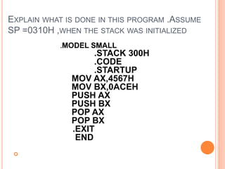
34. EXPLAIN WHAT IS DONE IN THIS PROGRAM .ASSUME
SP =0310H ,WHEN THE STACK WAS INITIALIZED
.MODEL SMALL
.STACK 300H
.CODE
.STARTUP
MOV AX,4567H
MOV BX,0ACEH
PUSH AX
PUSH BX
POP AX
POP BX
.EXIT
END
35. Program defines a stack of 300 bytes by the use of the
stack directive
It loads two numbers in AX & BX
Later these numbers are pushed into stack using PUSH
operation, followed by POP operations.
Note that POPing occurs in reverse direction
what is pushed in last will be popped out first
the last PUSH was PUSH BX
hence by the POP AX operation, the content of AX is
replaced by the content of BX
Similarly the second POP causes the BX to get the
content of AX
Thus this program will exchange the contents of these two
registers, using the stack as a temporary data storage area
After execution, the contents of the registers are:
BX=4567H & AX=0ACEH
36. BRANCHING INSTRUCTIONS
Branching instructions is very important as they carry
the full power of a computer
Branching can be of two types: Conditional & Un-
Conditional
Unconditional branching becomes necessary when
looping back or forward is done infinitely (Like generating
square wave)
Conditional branching is what may be more important
taking decisions based on the result of a computation
that gives computers their power & versatality
Most instructions becomes meaningful when only
conditional branching is used.
37. JMP- JUMP
Usage: JMP destination
Here destination is a memory location
Jump destination is referred as ‘target’
Jump instructions breaks the normal sequence of
program execution and takes control to a different
location in code segment
small example
MOV…..
ADD,-----
JMP AGAIN
………..
--------
-
-
------------
AGAIN: ……..
38. When the ADD instruction is being executed ,
IP(Instruction Pointer) points to the next
instruction which is an unconditional JMP
instruction .
On decoding the JMP instruction ,the
EU(Execution Unit) realizes that the next
instruction should be taken from the location with
label AGAIN .
It is obvious then , that the IP content must be
changed in such a way that a new sequence is
to be followed .
39. SALIENT POINTS REGARDING JUMP
The label of the destination address should be
followed by a colon.
Jumping can be backward or forward in the
program sequence
Jumping can be unconditional .Then the format of
the jump instruction is
JMP label ,where label is the address of the
destination
JMP can be conditional, based on the state of the
flags which gets affected by arithmetic or logic
instructions
40. TYPES OF JUMP INSTRUCTIONS
an intrasegment (within segment) or near jump-
needs a new value for IP
jump location may be in a different code segment –
i.e. inter segment -then it is called a far jump –needs
a new value for CS and IP
43. OTHER FORMS OF THE UNCONDITIONAL JUMP
INSTRUCTION
i) JMP reg16
This is called an indirect jump
The 16-bit registers contains the destination
address (OffSet)
This Jump is not a relative jump
IP gets replaced by the value in the register
examples:
JMP BX ;jump to the destination address in BX. Make
IP=BX
JMP SI ; jump to the destination address in SI. Make
IP=SI
44. ii. JMP [reg 16]
The register points to an address which contains
the jump location
e.g.JMP [SI] ; jump to the address which is stored
in the memory location pointed by SI
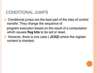
45. CONDITIONAL JUMPS
Conditional jumps are the best part of the idea of control
transfer. They change the sequence of
program execution based on the result of a computation
which causes flag bits to be set or reset.
However, there is one case ( JCXZ) where the register
content is checked.
46. LIST OF CONDITIONAL JUMP INSTRUCTIONS WHICH CATER TO
UNSIGNED ARITHMETIC AND WHICH
DIRECTLY ADDRESS FLAGS OR REGISTERS
48. FAR JUMP
A far jump is an intersegment jump, which means
that the destination address is in a different
code segment.
This will be a 5-byte instruction, the first byte being
the opcode, the second and third, the new value of
IP, and the fourth and fifth, the new values of CS.
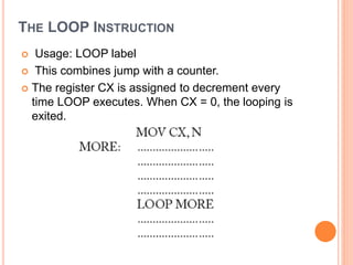
49. THE LOOP INSTRUCTION
Usage: LOOP label
This combines jump with a counter.
The register CX is assigned to decrement every
time LOOP executes. When CX = 0, the looping is
exited.
50. What is to be understood here is that, the sequence
of instructions up to the line containing the LOOP
instruction, will execute once.
Then, when the LOOP instruction is encountered,
CX is decremented and then tested. If CX is found
to be equal to zero, looping is exited and the next
instruction in the sequence is taken up.
If CX! = 0, control returns to the label MORE.
51. LOOP can be combined with other conditions, to
make it a conditional instruction.
LOOPNE / LOOPNZ and LOOPE / LOOPZ can be
used.
These instructions test the zero flag, as well as the
value of CX
53. ARITHMETIC INSTRUCTIONS
Complete list of Arithmetic instructions is shown
below
Instruction from 1 to 9 are discussed in detail
For signed number arithmetic is discussed later
56. FLAG CONTROL INSTRUCTIONS
Certain instructions which can be used to set/reset flags
very relevant in case of flags like direction flag, interrupt
flag etc..
There is one conditional flag which can be set/reset using
instructions, and that is the carry flag.
Relevant instructions to it are:
i) CLC – Clear carry.
ii) STC – Set carry.
iii) CMC – Complement carry
some of the important and commonly used arithmetic
instructions with its format & usage are discussed.
57. ADDITION INSTRUCTIONS
ADD – Add.
Usage: ADD destination, source.
This instruction adds the destination and source and puts
the sum in the destination. All conditional flags get affected.
Examples…
ADD AH, AL ; add AL to AH, sum in AH
ADD AL, COSTP ; add the byte in COSTP to AL, sum in AL
ADD BX, 0987H ; add the number 987H to BX, sum in BX
ADD CX, [BX] ; add the word in the location pointed by BX
to CX sum in CX
58. ADC – Add with carry
Usage: ADC destination, source
This instruction adds CF and source to the
destination, and puts the sum in the destination. There are
three operands, of which the third is the carry. All
conditional flags get affected.
Examples….
ADC AH, 0 ; AH=AH+0+CF
ADC [BX], AL ;add the byte pointed by BX with AL and
CF, put sum in the location pointed by BX
ADC AX, [BX][SI] ; add to AX, CF and the word with
EA=BX+SI sum in AX
59. INC – Increment
Usage: INC destination
This instruction adds 1 to the destination. All conditional
flags, except the carry flag, get affected.
Examples…
INC BX ; add 1 to the content of BX
INC [BX] ; add 1 to the content of the m emory location
pointed by BX
INC AH ; add 1 to the content of AH
60. PTR DIRECTIVE
When the size of the operand is not implicit in the
instruction, a pointer is used to indicate whether
the operand is a byte, a word, or a double word.
This is the PTR directive.
Examples …
INC BYTE PTR [BX] ;byte pointer
or INC WORD PTR [BX] ;word pointer
or INC DWORD PTR [BX] ;double word pointer
62. First AX is loaded with 0
lets see how a byte addition causes a result to be a word
the sum of two bytes which are added to AL is too large to
fit in AL
It needs to generate a carry flag
next instruction adds CF,0 and AH which contains a 0
so the carry bit is accommodated in AH
Thus AH-AL, i.e AX contains the sum in which is a word
63. SUBTRACTION
SUB – Subtract.
Usage: SUB destination, source.
This instruction subtracts the source from the destination.
The result is in the destination.
All conditional flags are affected.
Examples…
SUB AX, BX ;subtract BX from AX
SUB AL, [BX] ; Subtract the byte pointed by BX from
AL
SUB COST[SI], CX ; Subtract CX from the word with
EA=COST+SI
SUB AX, 8956H ;Subtract 8956H from AX
SUB CL, BYTE PTR[SI] ; subtract from CL the byte
pointed by SI
64. SBB – SUBTRACT WITH BORROW
Usage: SBB destination, source
This instruction subtracts the source and the carry
flag from the destination. All conditional flags are
affected.
• Examples…
SBB CH, 7 ;subtract from CH, 7 and CF – result in
CH
SBB AX, [BP + 2] ; subtract from AX, the word
pointed by [BP+2]. Since BP is used, the data is
taken from the stack segment. The result in AX
65. DEC – DECREMENT
Usage: DEC destination.
This instruction subtracts 1 from the destination. All
conditional flags, except the carry flag, are
affected.
Examples..
DEC CL ;subtract 1 from CL
DEC WORD PTR [SI] ; subtract 1 from the word
pointed by SI
DEC BYTE PTR NUMB[BX] ;subtract 1 from the
byte pointed by the effective address NUMB+BX
66. UNSIGNED MULTIPLICATION
MUL – Multiply.
Usage: MUL source.
This instruction multiplies a number in AL or AX by
the source (where the source can be a register or a
memory location, but not an immediate number).
All the conditional flags are affected, but only the
CF and ZF are defined as meaningful for the result.
The destination depends on the size of the
operand.
67. Two ways of performing multiplication
i) Byte by byte
In this, one of the operands must be in the AL
register, and the source can be a byte in a
register or memory location. The product (a
word) will be in AX.
Examples ….
MUL BL
MUL BYTE PTR[SI]
MUL BIG
68. ii) Word by word
In this, one of the operands must be in the AX
register, and the source can be a word in a
register or memory location. The product will be
in DX and AX, with the upper word in DX.
Examples…
MUL CX
MUL WORD PTR [DI]
69. iii)Word by byte
This is only a special case of the word × word
multiplication. The byte must be extended to be a
word by making the upper byte to be 0. If the
byte is in AL, extend it to be a word by making
the content of AH to be zero. Th us, AX now
contains one of the operands.
70. UNSIGNED MULTIPLICATION-FLAGS
AFFECTED
All conditional flags are affected, but only the carry
(CF) and overflow (OF) flags have any significance.
They will be set or reset according to the size of the
product.
We can summarize that if the product has a size
equal to the size of the operands, both these flags
are reset. i.e. CF = 0, OF = 0.
However, if the product is large enough to occupy
the registers assigned for it, these flags are set i.e.,
CF = 1, ZF = 1.
71. Two bytes stored in the data segment are multiplied. The result of
multiplication is available in AX, which is then moved to the location PROD,
a word location. Write a program for this.
72. FACTORIAL
.Model Small
.Data
Fact DW 0 ;space allocated for the factorial
.Code
.Startup
Mov ah,01
int 21h ; enter N from the KB
sub al,30h ;convert ASCII to binary
mov ah,0 ;convert N in AL to a word in AX
mov bx,ax ;mov to bx
mov ax,1 ; ax=1, to start the iteration
cmp bx,0 ; compare bx(=N) to 0
jz final ; if N=0, jump to find 0!
repea: mul bx ; for N not 0, multiply with AX
dec bx ; decrement BX
cmp bx,0 ;compare with 0
jne repea ;repeat if BX is not 0
final: mov fact,ax ; AX=1, hence 0!=1
.exit
.end
73. UNSIGNED DIVISION
DIV – Divide
Usage: DIV source
This instruction divides AX or DX – AX by the
source, where the source can be a register or a
memory location, but not an immediate number.
• All the conditional flags are affected, but
undefined – hence they do not give any
interpretation or information about the result.
74. WAYS OF PERFORMING DIVISION
i. Divide a word by a byte
Here, the dividend must be a word placed in AX
and the source must be a byte. The result of
division causes AL to contain the quotient, and AH
to contain the remainder.
Examples………
DIV BL
DIV BYTE PTR [BX]
DIV DIG
75. ii. Dividing a byte by a byte.
This is just a special case of a division of a word by
a byte. In this case, convert the dividend byte to a
word by loading the dividend in AL and 0 in AH.
Thus, AX will be the word that acts as the dividend.
76. iii. Divide a double word by a word.
In this case, the dividend has to be in AX and DX
(the upper word in DX). The divisor should be a
word.
The result of this division causes the quotient to be
in AX and the remainder to be in DX.
Examples…
DIV BX
DIV WORD PTR [SI]
DIV ANGLE
77. iv. Dividing a Word by a Word.
Similar to the previous case, if we want a word by
word division, extend the word in AX to be a double
word by loading 0 in DX to get the dividend to be a
double word in AX and DX.
78. DIVIDE BY ZERO ERROR
For division, if the divisor is zero, the quotient
becomes undefi ned. In attempting such a division,
the 8086 will exit from this program and generate
an interrupt.
This state is said to be a ‘divide by zero error’. An
interrupt generated by an error, is termed an
exception.
If the quotient register is too small to accommodate
the quotient, then also this happens.
79. MOV AX, 09876H
MOV CL, 25H
DIV CL
The above program segment will give a quotient of
41EH, which obviously cannot be accommodated in
AL.
Then ,program execution is aborted and the
assembler
displays the message ‘divide overflow error’.
80. WRITE A PROGRAM TO FIND THE AVERAGE OF TWO
BYTES STORED IN MEMORY