2. Contents
Sr. No. Description Page No.
01 MEETING 03
02 TYPES OF CONTRACT 04
03 MONITORING 05
04 SCOPE OF THE PROJECT 06
05 PROJECT COMPLETION SCHEDULE 07
06 BUDGET 08-12
07 GUIDELINES FOR THE DESIGN OF FLEXIBLE PAVEMENTS 13
08 GUIDELINES FOR THE DESIGN OF PLAIN JOINTED RIGID PAVEMENTS 14
09 GUIDELINES ON TRAFFIC MANAGEMENT IN WORK ZONES 15-17
10 CODE OF PRACTICE FOR ROAD SIGNS 18-22
11 SITE ENGINEERING DATA 23-29
12 MINISTRY OF ROAD TRANSPORT AND HIGHWAYS 31-101
13 TESTS ON COMPLETION 102-103
14 ABBREVIATION AND SYMBOLS 104-107
3. MEETING
A meeting is a gathering of two or more people that has been convened for the purpose of
achieving a common goal through verbal interaction, such as sharing information or reaching
agreement.
There are six general types of meetings:-
1. Status update meeting
2. Information sharing meeting
3. Decision making meeting
4. Problem solving meeting
5. Innovation meeting
6. Team building meeting
3
4. TYPES OF CONTRACT
• Lump Sum or Fixed Price Contract
• Measurement Contract
• Turnkey Contract
• BOT
• DBFOT
• EPC
• HAM
• Annuity Based Contract
• Unit Prise Contract
• Time and Material Contract
• Item rate Contract/BOQ
• Percentage rate Contract
• Labour Contract
• Piece-Work Agreement
• Target Contract
4
5. MONITORING
• Monitoring is a regular observation and recording of activities taking place in a project or
programme. It is a process of routinely gathering information on all aspects of all the
project, to monitor is to check on how project activities are progressing.
• Project Monitoring refers to the process of keeping track of all project related metrics
including team performance and task duration, identifying potential problems and taking
corrective actions necessary to ensure that the project is within scope, on budget and meets
the specified deadlines.
5
6. SCOPE OF THE PROJECT
Under this Agreement, the scope of the project shall mean and include:-
a. Construction of the Project Highway on the Site set forth in Schedule-A and as specified in
Schedule-B together with provision of Project Facilities as specified in Schedule-C, and in
conformity with the Specifications and Standards set forth in Schedule-D.
b. Maintenance of the Project Highway in accordance with the provisions of this Agreement
and in conformity with the requirements set forth in Schedule-E and
c. Performance and fulfilment of all other obligations of the Contractor in accordance with
the provisions of this Agreement and matters incidental thereto or necessary for the
performance of any or all of the obligations of the Contractor under this Agreement.
6
7. PROJECT COMPLETION SCHEDULE
(As per EPC/HAM Agreement) During Construction period the contractor shall comply with
the requirements set forth in the Schedule-J/G for each of the Project Milestones and the
Scheduled Completion Date. Within 15 days of the date of each Project Milestone, the
Contractor shall notify the Authority of such compliances along with necessary particulars
thereof. The Project Milestones may be as below:-
Project Milestone-I
Project Milestone-II
Project Milestone-III
Scheduled Completion Date
On or before the Scheduled Completion Date, the Concessionaire/Contractor shall have
completed the Project in accordance with this Agreement.
7
8. BUDGET
It is a financial disposal limit that is needed for Project implementation. It constitutes cost
of material, machinery, manpower & other resources necessary for execution of the Project
in a time bound manner.
The construction budget is the amount of money allotted for a specific Project or
remodelling of the project. Construction budgets are used to anticipates all costs and
expenses of the building process. A budget is usually tracked through a form or spreadsheet.
Although most construction budgets may appear constraints, planners often leave room for
emergencies or unexpected building costs that may arise during the Project.
To be sure, the best starting point for these costs is the Project plans or blueprints, which
address possible materials that will be used through out construction period of the Project.
8
9. BUDGET
• A project budget reflects the financial plan of operations, divided into responsibility centers,
with specific goals clearly outlined along with costs expected to be incurred. The primary
purpose of having a budget is to assign financial targets and resources to each responsibility
center, to coordinate their activities, to form the basis for controlling performance, and to
make the participant cost conscious instead of purposeless routine accounting.
• The breakdown of the project cost may include the following:
• Land Procurement Cost;
• Preliminary expenses for approval of projects from appropriate authorities;
• Legal expenses;
• Finance engineering expenses;
• Corporate office overhead;
• Project office expenses;
• Cost of construction;
• Engineering and Architect’s expenses; and
• Contingencies.
9
11. BUDGET
• A Road Project’s Budget may describe the following:-
1 Engineering 5 TAXES & DUTIES
Design & Consultancy GST
2 Procurement
Building & Other Construction Worker
Cess
Material Royalty
Misc. Civil Expenses Entry Tax
Shuttering & Scaffolding 6 Financial Charges
3 Project Management Financial Charges
Employee Benefit Expenses + Labour Insurance
Administrative Expenses Business Promotion
Site Establishment / Camp Construction 7 Other Overheads
4 Construction Contingencies
Plants & Equipment HO Overhead
Sub-contracts (Item Rate) Mobilisation & Demobilisation
Sub-contracts (Labour Rate) Utility Shifting 11
12. BUDGET
Various Requirement of Project (Variable)
Sr. No. Description Sr. No. Description
1 GSB 21 Royalty Payment Earthwork, Aggregate
2 6mm Aggregate 22 Aggregate Transportation Charges
3 10mm Aggregate 23 Electricity charges
4 20mm Aggregate 24 Guest House & Office Rent
5 26.5 mm Aggregate 25 Labour Requirement
6 40mm Aggregate 26 Mess Charges incl gas
7 Dust 27 Mobile & Internet Charge
8 Sand 28 NMR Salary
9 Cement 29 Security Bill
10 Steel Reinforcement (Dia Wise) 30 Staff Salary
11 Flyash 31 Staff Welfare, House Keeping etc.
12 Dowel Bar Cap/Sleaves. 32 Stationaries
13 Seperation membran 33 Sub Contractor Bill
14 Curing Compound Resin Based 34 Toner Refill Expenses
15 Admixture 35 Vehicle Hire Charges
16 Joint sealant 36 Water charges
17 Sealant primer 37 Other Miscellaneous for office
18 RCC (NP-4) Hume Pipe (Dia Wise) 38 Mech. Dept. Spare parts expenses
19 100mm Dia PVC Pipe for Weep Hole 39 Cost of Bitumen
20 Diesel (HSD) 40 Suppliers Billing i.e. Bearings etc.
12
13. GUIDELINES FOR THE DESIGN OF FLEXIBLE PAVEMENTS
IRC:37-2018(Fourth Revision)
Some of the salient features of this forth revision are:-
a. Recommendation of better performing bituminous mixes and binders for surface and
base/binder courses.
b. Guidelines for selection of appropriate elastic moduli for bituminous mixes used in
the surface and other courses.
c. Recommendation of minimum thickness of granular and cement treated subbase and
base and bituminous layers from functional requirements.
d. Generalization of the procedure for the estimation of the effective resilient
modulus/CBR of subgrade.
e. Provision for the use of geo-synthetics and
f. Rationalization of the design approach for stage construction.
13
14. GUIDELINES FOR THE DESIGN OF PLAIN JOINTED RIGID PAVEMENTS FOR
HIGHWAYS
IRC:58-2015(Fourth Revision)
The Salient Features of the Current Guidelines are:-
a. Design of pavements considering the flexural stress under the simultaneous action of
load and temperature gradient for different categories of axles.
b. Design considering sum of cumulative fatigue damages caused by single tandem and
tridem axle load applications due to tensile flexural stresses at the top and the bottom
of the pavement slab.
c. Consideration of in-built permanent curl in the analysis of flexural stresses.
d. Design guidelines for pavements without concrete shoulders and with tied concrete
shoulders.
e. Consideration of Concrete slabs with unbonded as well as bonded cement bound
subbase.
f. Design of pavements with widened outer lanes.
g. Design of longitudinal, expansion and contraction joints.
14
15. GUIDELINES ON TRAFFIC MANAGEMENT IN WORK ZONES
IRC:SP:55-2014 (First Revision)
• The road construction and maintenance activities are the integral part of the road network
development particularly for developing and transitional economies. Improving and
expanding the roadway network is critical to economic development as well as the quality of
life and, these activities create work zones in the network.
• Work zone accidents are caused by several factors such as frequently changing environment
that occurs during road work whereby the driver is often surprised, insufficient warning signs
for normal and construction traffic, lack of audible warning to workers and, inadequate
provisions of safety devices to protect workers.
• To ensure safety of all, there is a need to adopt an efficient and effective plan for management
of traffic in work zones. Work Zone Traffic Management Plans (WTMPs) are required to meet
the safety needs of regular traffic as well as works traffic, ensuring minimum disruption in
access to properties and movement of pedestrians.
15
16. GUIDELINES ON TRAFFIC MANAGEMENT IN WORK ZONES
IRC:SP:55-2014 (First Revision)
• The primary purpose of the Work Zone Traffic Management Plans is to provide for the
reasonably safe and efficient movement of road users through or around the work zones
while reasonably protecting the workers and equipment.
• The WTMP, therefore, should facilitate the smooth and efficient flow of traffic as well as safe
working environment.
• The traffic management in construction of highways, especially where the existing
alignment is used for upgrading to 4/6 lanes, the existing traffic has to be managed for their
safety during the construction. The construction zone traffic management is difficult in this
country at all locations across the whole country. The arrangements of diversions, diversion
road surface, traffic signs and marking, warning and barricading of the highly hazardous
locations, etc are grossly violated.
16
17. COMMONLY USED TERMS IN SAFETY
• Activity Zone
• Advance Warning Length (AWL)
• Delineators
• Diversions
• Drums
• Hazard Markers
• Normal Regulatory Signs
• Ordinary Road Marking Paints
• Personal Protective Equipment (PPE)
• Portable Traffic Signals
• Portable Variable Message Signs
• Priority Sign
• Protective Gears for Workers
• Regulatory Signs
• Retro Reflective Tape
• Safety Auditor
• Safety Ribbon Tape
• Stop/Go Boards
• Temporary Traffic Control Zone
• Traffic Cones
• Traffic Control Devices
• Vulnerable Road Users (VRUs)
• Warning Sign
• Water-Filled Barricades
• Work Zone End
• Work Zone Informatory Sign
• Work Zone Regulatory Signs
• Work Zone Warning Signs
The commonly used terms in these guidelines are described hereunder and shall be applicable
wherever they are used:-
17
18. CODE OF PRACTICE FOR ROAD SIGNS
IRC:67-2012(Third Revision)
• This Code contains the basic principles that govern the design and use of road signs for all
categories of roads including expressways open public travel irrespective of road agency
having jurisdiction.
• Design, placement, operation, maintenance, and uniformity are aspects that should be
carefully considered in order to maximise the ability of a road sign to meet the
requirements.
18
19. CLASSIFICATION OF ROAD SIGNS
Road signs are classified under the following three heads:
Mandatory/Regulatory signs:-
All Mandatory or Regulatory Signs are circular in shape. Mandatory/
Prohibitory Signs are to indicate the prohibition upon certain kind of
vehicle maneuver and vehicle type like "overtaking prohibited" or "U-turn
prohibited" or "cycles prohibited" and restriction on parking like "parking
prohibited" and limit on vehicle speed and size like "speed limit" and
"maximum load limit" . They are with red circular ring and diagonal bars
with black symbols or arrows or letters on white background. The red ring
indicates prohibitory regulation; and the diagonal red bar prohibits the
action or movement indicated by the black symbol. Mandatory signs giving
positive instructions are circular with white symbol on a blue background.
They indicate what driver must do compulsorily. For example, direction
control signs are to compulsorily regulate certain movements wherever the
restriction applies.
Mandatory and regulatory signs need to be complied with and any
violation of the rules and regulations conveyed by these signs is a legal
offence.
19
20. CLASSIFICATION OF ROAD SIGNS
• Cautionary/Warning Signs:-
Cautionary/Warning signs are triangular in shape with red border and
black symbol in white background used to caution and alert the road
users to potential danger or existence of certain hazardous conditions
either on or adjacent to the roadway so that they take the desired
action. These signs indicate a need for special caution by road users and
may require a reduction in speed or some other maneuver. Some
examples of these signs are Hairpin Bend, Narrow Bridge, Gap in
Median, School Ahead etc. An example is shown in Figure 3.2.
• Informatory/Guide Signs:-
All Informatory signs and Guiding signs for facilities are rectangular in
shape. Informatory Signs for facilities indicates location and direction to
facilities like "fuel station" or "eating place" or "parking" and shall be a
symbol within a rectangular board with blue background. Information
signs in rectangular shape are also used with destination names and
distances with arrows indicating the direction as per the figures.
20
22. CONCLUSION ON SAFETY
Road safety is a task which cannot be achieved without contribution from multiple
agencies. Road safety is not only for road and vehicle. A whole range of stakeholders with genuine
need to deliver their responsibility by individual organisation makes difference in road safety. It is a
systematic approach, which have to be pursued, and therefore, entire system must be synchronise.
Making good and safe roads will meet only part of the problem, and with every other agency
following rule will ensure safety.
Requisite for Road safety are,
• Reduce unsafe behaviours and increase safe behaviours (By imposing law and fines)
• Improving driving skills (By better driving licence procedure)
• Increase awareness about the rules of the road
• Target unsafe actions, i.e., distracted driving (Mobile phones) and drunk driving.
• Address specific segment of people by different mean.
22
23. SITE ENGINEERING DATA
For All Site Civil Engineers
• Units and Dimensions:
A dimension is a measure of a physical variable (without numerical values), while a unit is a way
to assign a number or measurement to that dimension. For example, length is a dimension, but it
is measured in units of feet (ft) or meters (m).
There are four types of systems for measurements:-
1. CGS - Centimetre Gram Second
2. FPS - Foot Pound Second
3. MKS - Meter Kilogram Second
4. SI - International System of Units
23
24. SOME IMPORTANT CONVERSIONS
• 1 Micron= 1/1000mm = 1/ 103
mm = 1 x 10⁻³
mm
• 1 Micro Meter = 1X10-3
X 10-3
=1X10⁻⁶
Meter (One Millionth of a Meter )
• 1 Nano Meter = 1X10-6
X 10-3
=1X10⁻⁹
Meter (One Billionth of a Meter )
• 1 Pico Meter = 1X10-9
X 10-3
=1X10-12
Meter (One Trillionth of a Meter )
• 1 cm = 10 mm
• 100 cm = 1 meter = 1000 mm
• 1000 meter = 1 km
• 1 inch = 2.54 cm = 25.4 mm
• 1 feet = 30.48 cm = 304.8 mm
• 1 meter = 3.28 feet
• 3 feet = 1 yard
• 1760 yard = 1 mile = 5280 feet = 1609 meter = 1.609 km
• 1 revenue chain = 66 feet = 22 yard (@20 meter)
• 1 engineering chain= 100 feet (@30 meter)
24
25. SOME IMPORTANT CONVERSIONS
• 1 acre = 10 revenue chain (L) x 1 revenue chain (B)
= 660 feet x 66 feet = 43560 sqft
• 1 acre = 100 decimal = 43560 sqft
• 1 decimal = 435.60 sqft
• 1 aare = 10 m x 10m = 100 sqm
• 100 aare = 1 hectare = 100 x 100 sqm = 10000 sqm
• 1 sqm = 3.28 feet x 3.28 feet = 10.758 sqft
• 1 acre = 43560 sqft = 43560/10.758 = 4049 sqm =
0.4049 hectare
• 1 hectare = 10000 sqm = 2.47 acres
• 1 cubic meter = 1 m x 1 m x 1 m = 1 m3
= 3.28 ft x 3.28 ft x 3.28 ft = 35.287 cft
• 100 cft = 2.833 cum
25
26. SOME IMPORTANT CONVERSIONS
• MEASURMENTS
LINE :- In plane geometry the word ‘Line’ is usually taken to mean a straight line. If a set of points
are lined up in such away that a line can be drawn through all of them, the points are said to be collinear.
Length, Breadth/Width, Depth/Height all are denoting the meaning of line only in any type of
measurement.
Area = L x B in Sqft/Sqm
Volume = Quantity = Area x Height/Depth in Cft/Cum
• Weight :- Gram, Pound, Kilogram, Metric Tonne
1 Gram = 1000 milligram
1000 Gram = 1 kilogram
1000 Kilogram = 1 Metric Tonne
1 Kilogram = 9.81 Newton say 10 Newton = 1000 Grams
1 Newton = 101.936 Gram, say 100 Grams
1 Pound = 453.6 Gram
1 Kilogram = 2.204 Pound
26
27. SOME IMPORTANT CONVERSIONS
MEASUREMENTS
Standard weight of 1 meter steel bars:-
1. 6 mm = 0.222 kg
2. 8 mm = 0.395 kg
3. 10 mm = 0.617 kg
4. 12 mm = 0.888 kg
5. 16 mm = 1.578 kg
6. 20 mm = 2.469 kg
7. 25 mm = 3.853 kg
8. 32 mm = 6.320 kg
How to find the weight of any diameter of 1 meter length bar
Density of steel = 7850 kg per cum
e.g. taking 20 mm dia bar
Weight = Volume x Density
= π/4 x D2
x L x Density
= π/4 x (0.020 m x 0.020 m) x 1 m x 7850 kg/ m3
= 2.469 m3
x kg/ m3
= 2.469 kg
27
28. SOME IMPORTANT CONVERSIONS
MEASURMENTS
• How to find the weight of steel = D2
/162
• Weight of steel (W) = π/4 x D2
x L x Density
= 3.14/4 x D2
x 1m x 7850 kg/ m3
= 0.785398 x D2
x 1m x 7850 kg/ m3
= D2
x 0.785398 x 1m x 7850 kg/ m3
= D2
x 6165.375 x 1 kg/ m2
We know that x/y = x/y and (x/y)/(x/y) = 1
Hence W = (D2
x 1 kg/1)/(m x m)/6165.375
= (D2
x 1 kg/1)/(1000 mm x 1000 mm)/6165.375
= (D2
x 1 kg/1)/162 = D2
/162 kg
28
29. SOME IMPORTANT CONVERSIONS
MEASURMENTS
Time:-
60 second = 1 minute
60 minutes = 1 hour = 3600 seconds
24 hour = 1 Day
7 Days = 1 Week
15 Days = fort night
30 Days = 1 month
365 Days = 1 year
10 years = 1 decade
100 years = 1 century
1000 years = 1 millennium
AM = Anti Meridiem
PM = Post Meridiem
1 Million = 10,00,000 (10 Lakhs) = 1000 times of 1000 = 103
x 103
= 106
1 Billion = 1000 Million = 1000 times of 1 Million = 1000 x 106
= 109
1 Trillion = 1000 Billion = 1000 times of 1 Billion = 1000 x 109
= 1012
29
30. ‘’Black Color Is Sentimentally Bad, But Every Blackboard Makes The Students Life Brighter’’
30
31. MINISTRY OF ROAD TRANSPORT AND HIGHWAYS
• First Published : April, 1973
• Second Revision : February, 1988
• Third Revision : April, 1995
• Fourth Revision : August, 2001
• Fifth Revision : April 2013
In the last decade and a half, significant developments have taken place in the highways
sector. The massive National Highway Development Projects (NHDP) undertaken by the
Government of India is in progress involving execution of a large number of high value road
projects. These require adoption of latest international practices so as to achieve technical
excellence and the best quality. The Fifth revision of the Specification for Road and Bridge Works
is the result of the concreted efforts of the officers of the Roads Wing and other professionals
who contributed to the drafting of this document.
31
32. CONTENTS OF MORTH
SECTION No. DESCRIPTION
100 GENERAL
200 SITE CLEARANCE
300 EARTHWORK, EROSION CONTROL AND DRAINAGE
400 SUB-BASES, BASES (NON BITUMINOUS) AND SHOULDERS
500 BASES AND SURFACE COURSES (BITUMINOUS)
600 CONCRETE PAVEMENT
700 GEOSYNTHETICS
800 TRAFFIC SIGNS, MARKINGS AND OTHER ROAD APPURTENANCES
900 QUALITY CONTROL FOR ROAD WORKS
1000 MATERIALS FOR STRUCTURES
1100 PILE FOUNDATIONS
1200 WELL FOUNDATIONS
32
33. CONTENTS OF MORTH
SECTION No. DESCRIPTION
1300 BRICKS MASONRY
1400 STONE AND CONCRETE BLOCK MASONRY
1500 FORMWORK
1600 STEEL REINFORCEMENT
1700 STRUCTURAL CONCRETE
1800 PRESTRESSING
1900 STRUCTURAL STEEL
2000 BEARINGS
2100 OPEN FOUNDATIONS
2200 SUBSTRUCTURE
2300 CONCRETE SUPERSTRUCTURE
2400 SURFACE AND SUB-SURFACE GEOTECHNICAL INVESTIGATION
33
34. CONTENTS OF MORTH
SECTION No. DESCRIPTION
2500 RIVER TRANNING WORK AND PROTECTION WORK
2600 EXPANSION JOINTS
2700 WEARING COAT AND APPURTENANCES
2800 REPAIR OF STRUCTURES
2900 PIPE CULVERTS
3000 MAINTENANCE OF ROAD
3100 REINFORCED EARTH
3200 SOIL NAILING
34
35. The Contractor shall at all times, carry out work on the highway in a manner creating least
interference to the flow of traffic while consistent with the satisfactory execution of the same, For all
works involving improvements to the existing highway, the Contractor shall, in accordance with the
directives of the Engineer, provide and maintain, during execution of the work, a passage for traffic
either along a part of the existing carriageway under improvement or along a temporary diversion
constructed close to the highway, Before taking up any construction or maintenance operation, the
Contractor shall prepare a Traffic Management Plan for each work zone .This plan should include
The Provision of traffic safety devices and road signs in construction zones as per IRC:SP:55 and other
relevant IRC Codes and para 112.4
SECTION: 112- ARRANGEMENT FOR TRAFFIC DURING CONSTRUCTION
35
36. • In stretches where it is not possible to pass the traffic on part width of the carriageway, a temporary
diversion shall be constructed with 7 m carriageway and 2.5 m earthen shoulders on each side (total
width of roadway 12 m) with the following provision for road crust in the 7 m width:
• i) Earthwork
• ii) 200 mm (compacted) granular sub-base
• iii) 225 mm (compacted) granular base course
• iv) Priming and Tack Coat and
• v) Premix carpet with Seal Coat/Mix Seal Surfacing
SECTION: 112.3- Passage of Traffic along a Temporary Diversion
36
37. SECTION: 113- GENERAL RULES FOR THE MEASUREMENT OF WORKS FOR PAYMENT
• All measurements shall be made in the metric system. Different items of work shall be measured in
accordance with the procedures set forth in the relevant SECTIONs read in conjunction with the General
Conditions of Contract. The same shall not, however, apply in the case of lumpsum contracts.
• All measurements and computations, unless otherwise indicated, shall be carried nearest to the
following limits:
i) length and width 10 mm
ii) height, depth or thickness of
a) earthwork, subgrade, 5 mm
b) sub-bases, bases, surfacing 5 mm
iii) structural members 2.5 mm
iv) areas 0.01 Sqm
v) volume 0.01 Cum
• In recording dimensions of work, the sequence of length, width and height or depth or thickness shall be
followed.
37
38. SECTION: 120- FIELD LABORATORY
• The work covers the provision and maintenance of an adequately equipped field laboratory
as required for site control on the quality of materials and the works.
• The Contractor shall arrange to provide fully furnished and adequately equipped field
laboratory. The field laboratory shall preferably be located adjacent to the site office of the
Engineer and provided with amenities like water supply, electric supply etc. as for the site
office of the Engineer as described in this Section.
• The field laboratory building and equipment shall be the property of the Contractor. The
Employer and the Engineer shall have free access to the laboratory.
38
39. SECTION: 201- CLEARING AND GRUBBING
• This work shall consist of cutting, removing and disposing of all materials such as trees
bushes, shrubs, stumps, roots, grass, weeds, rubbish, top organic soil, etc. to an average depth
of 150 mm In thickness.
• Roadside trees, shrubs, any other plants, pole lines, fences, signs, monuments, buildings,
pipelines, sewers and all highway facilities within or adjacent to the highway which are not
to be disturbed shall be protected from injury or damage.
• All excavations below the general ground level arising out of the removal of trees, stumps,
etc., shall be filled with suitable material and compacted thoroughly so as to make the
surface at these points conform to the surrounding area.
39
40. Section: 201.5- Measurements for Payment
Clearing and grubbing for road embankment, drains and cross-drainage structures shall be
measured on area basis in terms of hectares. Cutting of trees up to 300 mm in girth and
removal of their stumps, including removal of stumps up to 300 mm in girth left over after
trees have been cut by any other agency, and trimming of branches of trees extending above
the roadway and backfilling to the required compaction shall be considered incidental to the
clearing and grubbing operations.
40
41. Section: 300- Earthwork, Erosion Control and Drainage
This work shall consist of excavation, removal and disposal of materials necessary for the
construction of roadway, side drains and waterways in accordance with requirements of these
Specifications and the lines, grades and cross-sections shown in the drawings or as indicated by
the Engineer.
Section: 305- Embankment Construction
These Specifications shall apply to the construction of embankments including sub-grades,
earthen shoulders and miscellaneous backfills with approved material obtained from approved
source, including material from roadway and drain excavation, borrow pits or other sources. All
embankments sub-grades, earthen shoulders and miscellaneous backfills shall be constructed
in accordance with the requirements of these Specifications and in conformity with the lines,
grades, and cross-sections shown on the drawings or as directed by the Engineer.
41
42. Section: 305.2- Materials and General Requirements
• The materials used in embankments, subgrades, earthen shoulders and miscellaneous
backfills shall be soil, moorum, gravel, reclaimed material from pavement, flyash, pond ash, a
mixture of these or any other material as approved by the Engineer. The following types of
material shall be considered unsuitable for embankment:
a) Materials from swamps, marshes and bogs;
b) Peat, log, stump and perishable material; any soil that classifies as OL, 01, OH or Pt
in accordance with IS:1498;
c) Materials in a frozen condition;
d) Clay having liquid limit exceeding 50 and plasticity index exceeding 25; and
e) Materials with salts resulting in leaching in the embankment.
• 305.2.1.2 : Expansive clay exhibiting marked swell and shrinkage properties ("free swelling
index" exceeding 50 percent when tested as per IS:2720 - Part 40) shall not be used as a fill
material. Where an expansive clay having "free swelling index" value less than 50 percent is
used as a fill material, subgrade and top 500 mm portion of the embankment just below sub-
grade shall be non-expansive in nature.
42
43. • 305.2.1.4 : The size of the coarse material in the mixture of earth shall ordinarily not exceed
75 mm when placed in the embankment and 50 mm when placed in the sub-grade.
However, the Engineer may at his discretion permit the use of material coarser than this
also if he is satisfied that the same will not present any difficulty as regards the placement
of fill material and its compaction to the requirements of these Specifications. The
maximum particle size in such cases, however, shall not be more than two-thirds of the
compacted layer thickness.
Table 300-1 : Density Requirements of Embankment and Sub-grade Materials
Sr. No. Type of Work Maximum laboratory dry
unit weight
As per 5th Revision
Maximum laboratory
dry unit weight
As per 4th Revision
1 Embankments up to 3 m height, not
subjected to extensive flooding.
Not less than 15.2 kN/cu.m 1.52 gm/cc
2 Embankments exceeding 3 m height or
embankments of any height subject to
long periods of inundation.
Not less than 16 kN/cu.m 1.60 gm/cc
3 Subgrade and earthen· shoulders/verges /
backfill.
Not less than 17.5 kN/cu.m 1.75 gm/cc
43
44. 1.75 gm /cc=17.5 kN/m3
• Conversion
1.75 gm /cc = (1.75 X 1k/1000 X 1N/100)/(1M/100X1M/100X1M/100)
= (1.75 X 1k X 1N X 100 X 100 X 100 )/(1000X100X1MX1MX1M)
= 17.5 kN/m3
Hence Proved.
17.5 kN/m3
= 1.75 gm /cc
17.5 kN/m3
= (17.5 X 1gmX1000 X 100)/ (100cm X 100 cm X 100 cm)
= 17.5 gm X 1/10 cm3
= 1.75 gm/cm3
Hence Proved.
44
45. 305.2.2.3 : Fly-Ash
• Use of fly-ash shall conform to the Ministry of Environment and Forest guidelines. Where fly-ash is
used the embankment construction shall conform to the physical and chemical properties and
requirements of IRC:SP:38-2001, "Guidelines for Use of Flyash in Road Construction". The term fly-ash
shall cover all types of coal ash such as pond ash, bottom ash or mound ash. A thick soil cover shall
bind the edge of the embankment to protect it against erosion. Minimum thickness of such soil cover
shall be 500 mm.
305.2.2.4 : Compaction Requirements
• It shall be ensured that the subgrade material when compacted to the density requirements as in Table
300-2 shall yield the specified design CBR value of the sub-grade.
Table 300-2 : Compaction Requirements for Embankment and Sub-grade.
Sr.
No
Type of work/material Relative compaction as percentage of max.
laboratory dry density as per 15:2720 (Part 8)
Subgrade and earthen shoulders Not less than 97%
Embankment, Not less than 95%
Expansive Clays
a) Subgrade and 500 mm portion just
below the subgrade.
b) Remaining portion of embankment
Not allowed
90-95%
45
46. Section: 305.3.5- Spreading Material in layers and Bringing to Appropriate Moisture Content
• The embankment and sub-grade material shall be spread in layers of uniform thickness in
the entire width with a motor grader. The compacted thickness of each layer shall not be
more than 250 mm when vibratory roller/vibratory soil compactor is used and not more
than 200 mm when 80-100 kN static roller is used. The motor grader blade shall have
hydraulic control suitable for initial adjustment and maintain the same so as to achieve the
specific slope and grade. Successive layers shall not be placed until the layer under
construction has been thoroughly compacted to the specified requirements as in Table 300-2
and got approved by the Engineer. Each compacted layer shall be finished parallel to the
final cross-section of the embankment.
46
47. DESIGN UNDERSTANDING
1. Pavement Designs will need to understand for utilizing
the Available material along Project Corridor.
2. The pavement will be designed for “ EFFECTIVE CBR”
3. Effective CBR is Combined CBR of Sub grade Portion
and its below 500mm portion which can be
OGL/Embankment Portion
4. The CBR effective will be worked out from the both
CBR of Sub grade and OGL/Embankment as per the
availability.
For same case if OGL CBR is 5%
required BA CBR will be 8% for
required design CBR i.e 7%
47
51. PHYSICAL PROPERTIES OF SOILS
• A soil mass is, in general, a three phase system composed of solid, liquid and gaseous matter.
Solid phase is comprised of mineral or organic matter or both. Mineral portion consists of
particles of different sizes and shapes. ,Organic fraction is the plant and animal residue
which may be present in various stages of decomposition. Solids enclose open spaces termed
as voids.
51
52. SOME DEFINITIONS AND RELATIONSHIPS (V0LUME-V0LUME)
• Void Ratio (s) :It is defined as the ratio of volume of voids to the volume of solids. It is
denoted by ‘e’
Thus e=VV/VS
• Void ratio is represented as a decimal such a 0.5, 0.6 etc. In nature, even though the
individual void sizes are larger in coarse grained soils, void ratio of fine grained soils are
generally higher than those of coarse grained soils. Thus in general it can be written than
e>0, because a soil has to contain some voids (either in the form of air or water). But there
can not be an upper limit to the void volume VV’ therefore some soils may have a value of ‘e’
even greater than unity.
• Porosity (n) : Porosity is defined as ratio of volume of voids to die total volume. It is
denoted by n
Thus n=VV/V
• It is generally expressed as a percentage, Porosity of a soil can not exceed 100% (as it would
mean Vv>V which is not possible) hi feet it has a much smaller value. It is also known as
percentage voids.Both porosity and void ratio are a measure of voids i.e. looseness or
denseness of the soil. However term ‘void ratio’ is more commonly use in soil mechanics.
52
53. • Degree of Saturation : It is the ratio of volume of water to the volume of voids. Generally
expressed as a % age.
• Air Content :It is the ratio of volume of air voids to the volume of voids, also expressed as %
age.
• Percentage Air Voids : It is the ratio of volume of air to the total volume.
• WATER C0NTENT : Also known as moisture content, it is equal to the ratio of mass of water
(Mw) to the mass of soil solids (MS). It is expressed as % age. Fine grained soils have higher
value of water content as compared to coarse grained soils. Water content is a very important
property of soils. Behavior of fine grained soils very much depends upon their water content.
• VOLUME - MASS RELATIONSHIPS : These relationships are in terms of mass density. As we
all know that mass per unit volume is known as mass density, following five different mass
densities are used in soil mechanics.
(1) Bulk mass density - It is defined as the total mass (M) per unit total volume (V).
It is also known as bulk density, wet density or simply density. It is expressed in Kg/m3
or gm/ml or gm/cm3
53
54. • Dry mass density : it is defined as mass of solids per unit total volume. The solids may
shrink during drying therefore the total volume is measured before drying.
• Saturated mass density : It is the bulk mass density of the soil when the soil is in fully
saturated condition.
• Submerged mass density : It is the mass density of the soil when it is in submerged
condition. As all of us know that volume of a soil in submerged condition displaces an equal
volume of water (Archimedes principle) thus the net mass of soil in submerged condition is
reduced.
• VOLUME WEIGHT RELATIONSHIPS : These relationships are in terms of unit weight. Just
on the lines of volume mass relationships which we have studied in the previous article,
there are five types of unit weights used in soil mechanics. [The only difference in bulk mass
density and unit weight is that of mass and weight respectively] Unit weight is also known
as specific weight.
• Bulk unit weight -It is defined as the total weight per unit total volume. It is also known as
total unit weight or wet unit weight. It is expressed in the units of N/m3
or KN/m3
• Dry unit weight - It is defined as weight of solids per unit total volume.
54
55. • Specific Gravity : Specific gravity of solids, (Gs). Sometimes written as G is defined as the ratio
of the weight (or mass) or a given volume of solids to the weight (or mass) of an equal volume of
water. The value of ‘G’ for a majority of soils lies between 2.65 and 2.80. Lower values are for
coarse grained soils.
• Apparent or mass specific gravity : is the specific gravity of soil mass and is defined as the
ratio of total weight (or mass) of a given mass of soil to the weight (or mass) of an equal volume
of water.
• Relative density : The soil corresponding to higher void ratio is called loose and that
corresponding to lower void ratio is called dense. If the soil grains are not uniform, then smaller
grains fill in the space between the bigger ones and the void ratios of such soils get reduced to as
low as 0.25 in the densest state. Static load alone will not change the density of grains
significantly but if it is accompanied by vibration, there will be considerable change in density.
Water present in the soil acts as lubricant to certain extent. Thus the change in void ratio would
change the density and this is turn changes the strength characteristics of granular soils. The
term used to indicate the strength characteristics in a qualitative manner is termed as Relative
density.
55
56. • Plasticity of soils : Plasticity of a soil is it’s ability to undergo deformations without cracking or
fracturing. A plastic soil can be moulded into various shapes when it is wet.
Consistency : showed that a fine grained soil can exist in four states namely liquid, plastic, semi-solid
and solid state. The water contents at which soil changes from one state to the other are known as
‘Consistency limits’.
A soil containing high water content is in a liquid state. It offers no shearing resistance and can flow
like liquids. It has no resistance to shear deformation and therefore shear stress equal to zero. As the
water content is reduced, the soil becomes stiffs and starts developing resistance to shear, deformation.
At some particular water content the soil becomes plastic. That water content at which soil changes
from liquid state to the plastic state is known as liquid limit (L.L.).
In other words we can say that liquid limit is the water content at which the soil ceases to be a liquid.
The soil in the plastic stage can be moulded into various shapes. As the water content is reduced
further, plasticity of the soil decreases. Ultimately it passes from the plastic state to the semi-solid state
and stops behaving plastically. It cracks when moulded. This water content at which soil changes it’s
state from plastic to semi-solid, is known as the plastic limit (P. L.).
In other words plastic limit is the water content at which the soil just fails to behave plastically.
56
57. When water content is still reduced below the plastic limit, the soil attains a semi-solid state. It
cracks when moulded. Volume of soil decreases with decrease in water content till a stage is
reached when further reduction in water content does not reduce the volume. The soil is said to
have attained a solid state. The water content at which soil changes from semi-solid state to the
solid state, is known as shrinkage limit, ws (S.L). Below this water content, soil surface starts
drying, with air entering the voids. The sample no longer remains saturated. Colour of soil also
begins to change from dark to light. The shrinkage limit therefore can also be defined as the
lowest water content at which the soil is fully saturated.
Plasticity Index : The numerical difference between liquid limit and plastic limit is known as
plasticity index. In other words it is the range of water content over which soil remains plastic.
57
58. • These are residual soils, having high percentage of clay mineral montmorillonite. They are
expansive soils having high swelling and shrinkage characteristics.
Properties :
1. They are dark grey to black in colour and may be any other colour also.
2. They are highly expansive in nature.
3. They are suitable for growing cotton crop.
4. They have extremely low bearing capacity.
5. They show cracks after drying.
6. They are extremely difficult to work with.
Effect of Black Cotton Soils on Construction of Buildings and Other Structures. Since these are
expansive soils of very low bearing capacity, they can cause failure of structures built on them.
This is due to the reason that moisture variation in soil will cause it’s shrinkage and swelling
alternatively. With the result, the foundation will develop additional moments. These moments
cause development of cracks in columns, beams and other parts of the structure. Ultimately,
the structure will fail.
58
BLACK COTTON (BC) SOILS
59. However, this can be prevented by using following methods:
(i) Using under-reamed piles as foundation. Piles should be taken to a zone of negligible
moisture variation.
(ii) Stabilizing soil by cement, lime, flyash or a combination of them in a suitable proportion.
(iii) By improving the bearing capacity of soil by geotextiles, geogrids, geomembranes etc.
Swelling and Shrinkage :The reduction in volume of a soil mass due to evaporation of pore
water is known as shrinkage. If water is added to such soils, increase in volume takes place,
which is known as swelling. The soils which exhibit these characteristics are called expansive
soils.
Consolidation : The compressibility of the soil can be due to any or combination of the
following factors:
(i) Compression of the solid matter.
(ii) Compression of water and air within the voids.
(iii) Escape of water and air from the voids.
• Compression of solid particles is negligibly small. Water is also incompressible under the
stresses usually encountered in soil engineering. Air is expelled quickly after the application
of load. The compression of saturated soils (no air) is mainly due to the expulsion of water
from the voids. 59
60. SOIL COMPACTION
• The process of expulsion of air from the voids of partially saturated soil, under the effect of
dynamic loadings such as rolling and tamping is known as compaction. Compaction is the
decrease in volume, brought intentionally so as to increase the density at an unaltered water
content. It is the process by which the soil particles are artificially rearranged by mechanical
methods and packed into a smaller volume.
• Compaction should not be confused with consolidation, although both the processes are
related with decrease in volume. Following table gives differences between compaction and
consolidation.
Compaction Consolidation
1. Compaction is reduction in volume under
dynamic loads such as rolling, tamping,
vibrating etc.
2. It is an artificial process.
3. It is applied to partially saturated soils .
4. Reduction in volume occurs due to expulsion
of air from the void s
5. It occurs instantaneously after the application
of load .
1.Consolidation is gradual reduction in volume
under sustained static loading.
2.This process occurs it self in nature.
3.This is applicable to fully saturated soils.
4.Reduction in volume occurs due to expulsion
o f water from the voids.
5 . It take s a lot o f time, especially for clay sit
may take years .
60
61. Necessity or Objects of Compaction:
• Purpose of compaction is to improve the qualities o f soils to be used either as a
subgrade material or in the embankment and shoulder fills of dams. Compaction
generally increases shear strength and helps to improve the stability and bearing
capacity of a soil. It also reduces the permeability and compressibility o f the soil.
Thus settlements resulting from swelling and shrinkage of sub-soils can also be
prevented.
• Compaction is measured in terms of dry density or unit weight of the soil i.e., the
amount o f soil solids that can be packed in a unit volume of soil.
• Compaction is defined as the maximum dry density that can ideally be obtained for a
soil at a given water content by applying compaction. It is only a theoretical concept
which can never be reached in practice, because no matter how much compactive
effort is used and in whatever manner, some air voids will always remain within the
soil.
• The compaction shall be done with the help of self-propelled single drum vibratory
roller or pad foot vibratory roller of 80 to 100 kN static weight or heavy pneumatic
type roller of adequate capacity capable of achieving the required compaction.
61
62. Relative Compaction:
The dry density achieved in the field is compared with maximum dry density obtained in the
standard proctor test and that in the modified proctor test. The ratio of dry density in the field to the
maximum dry density is known as relative compaction or percent compaction.
Relative compaction (%) = (Field density/Lab density) x 100
Moisture content of each layer of soil shall be checked in accordance with IS:2720 (Part 2), and
unless otherwise mentioned, shall be so adjusted, making due allowance for evaporation losses, that
at the time of compaction it is in the range of 1 percent above to 2 percent below the optimum
moisture content determined in accordance with IS:2720 (Part 8) as the case may be. Expansive
clays shall, however, be compacted at moisture content corresponding to the specified dry density,
but on the wet side of the optimum moisture content obtained from the laboratory compaction
curve.
After adding the required amount of water, the soil shall be processed by means of graders, harrows,
rotary mixers or as otherwise approved by the Engineer until the layer is uniformly wet.
Clods or hard lumps of earth shall be broken to have a maximum size of 75 mm when being placed
in the embankment and a maximum size of 50 mm when being placed in the subgrade.
62
63. SECTION: 3100- REINFORCED SOIL
The work covers construction of reinforced soil structures
together with the construction of earthwork in layers, assembly
and placing of reinforcing elements and facia elements during the
construction process and all associated works.
The reinforced soil retaining structures can be used as, (i)
Reinforced soil retaining wall,(ii) Reinforced soil abutment, (iii)
Reinforced soil slope.
Retained soil can be blended or natural borrowed. Properties of the retained soil are essential to determine
the lateral earth pressure. In case configuration as per Fig. 2A is adopted the earth pressure acting on the
reinforced fill will be a function of angle of friction of retained fill. The friction value of the retained fill in
this arrangement will be lesser than that of the reinforced fill. Hence the earth pressure acting on reinforced
soil mass will be more than the earth pressure compared to the case where the fill material in both zones are
identical. Properties of the retained soil/fill like grain size distribution, angle of internal friction (under
drained and undrained conditions), Atterberg limits, density, and permeability should be determined before
proceeding with design. If a retained fill is not permeable, drainage should be ensured by providing a
drainage bay between the retained and reinforced fill as well as the retained soil and the founding soil, if
required.
For the retained soil, the value of phi considered in design should be arrived at using a similar
approach for the reinforced soil as outlined in the subsequent sections.
63
64. • Reinforced Soil/Fill :The reinforced soil/fill is essentially borrowed. It is desirable that
the reinforced fill be free draining with majority of the shear strength component derived
from internal friction. The desirable gradation of the reinforced fill is shown in Table 1. The
gradation proposed would ensure that the fill is well graded, free draining and has adequate
shear strength once it is compacted.
The backfill should also have Plasticity Index, PI < 6 and Coefficient of uniformity Cu > 2.
Soil/Fill with more than 15 percent passing 75 micron sieve, but less than 10 percent of particles
smaller than 15 microns are acceptable provided PI is less than 6 and angle of friction is not less
than 30°.
Table 1 Desirable Gradation for Reinforced Soil Fil
Sieve Size Percentage Finer (in %)
75 mm 100
4.75 mm 85 - 100
425 micron 60 – 90
75 micron < 15
64
65. It is desirable that soil should have a resistivity > 5000 ohm-cm at saturation. Metal
reinforcement should not be used for soils with resistivity less than 1,000 ohm-cm. Soils with
resistivity between 1000 to 5000 ohm-cm may be used provided the water extract from the soil
does not show chlorides more than 100 ppm., sulphates do not exceed 200 ppm, and pH ranges
from 5-10. Water used for compaction shall have resistivity more than 700 ohm-cm.
Flyash confirming to IRC:SP- 58 can be used as reinforced as well as retained fill. The quality of
flyash should be controlled through periodical checks to ensure consistency and compliance to
specifications.
It is emphasized that the order of preference of reinforced fill should be Clean, free draining,
non-plastic fill meeting gradation and plasticity requirements specified earlier. Flyash should
be confirming to IRC SP-58.
Where the soil classifies as GM or GC, is acceptable as per gradation and plasticity norms and if
it is ensured that 80 - 90 percent of the quantity of material is available for the project value of
∅Design may be based on the results of the large size direct shear box tests mentioned above
with a limiting value of 38 degrees. A drainage bay of minimum 600 mm width at the back of
the facing is commonly used. It should be ensured that the aggregates are not friable, flaky,
elongated and are sound in strength.
65
66. RE WALL FACIA
Facing shall enable the construction within specified tolerances of vertical and horizontal
alignment and it should perform over the design life. The facing system should be able to meet
the functional requirements such as rigidity, flexibility, aesthetics, environmental
considerations etc. depending on location, purpose and use of structure. The contractor shall
provide facing for the reinforced soil slope as approved by the designer and shown in the
drawing plan.
Connection between the facia panels and the reinforcing element shall be done by using either
nut or bolt, HDPE inserts with bodkin joint, hollow embedded devices, polymeric/steel
strips/rods/pipes, fibre glass dowels or any other material shown in the drawings. Several
types of connections are being used.
66
67. SECTION: 400- SUB-BASES, BASES (NON-BITUMINOUS) AND SHOULDERS
Granular sub-base: This work shall consist of laying and compacting well-graded material on
prepared subgrade. The material shall be free from organic or other deleterious constituents
and shall conform to the gradings given in Table 400-1 and physical requirements given in
Table 400-2. Gradings III and IV shall preferably be used in lower sub-base. Gradings V and VI
shall be used as a sub-base-cum-drainage layer. The grading to be adopted for a project shall be
as specified in the Contract.
Where the sub-base
is laid in two layers
as upper sub-base
and lower sub-base,
the thickness of
Each layer shall
not be less than
150 mm.
Table 400-1 : Grading for Granular Sub-base Materials
IS Sieve
Designation
Percent by Weight Passing the IS Sieve
Grad- I Grad II Grad III Grad IV Grad V Grad VI
75.0 mm 100 - - - 100 -
53.0 mm 80-100 100 100 100 80-100 100
26.5 mm 55-90 70-100 55-75 50-80 55-90 75-100
9.50 mm 35-65 50-80 - - 35-65 55-75
4.75 mm 25-55 40-65 10-30 15-35 25-50 30-55
2.36 mm 20-40 30-50 - - 10-20 10-25
0.85 mm - - - - 2-10 -
0.425 mm 10-15 10-15 - - 0-5 0-8
0.075 mm <5 <5 <5 <5 - 0-3
67
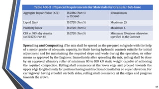
68. Table 400-2 : Physical Requirements for Materials for Granular Sub-base
Aggregate Impact Value (AIV) IS:2386 (Part 4)
or IS:5640
40 maximum
Liquid Limit IS:2720 (Part 5) Maximum 25
Plasticity Index IS:2720 (Part 5) Maximum 6
CBR at 98% dry density
(at IS:2720-Part 8)
IS:2720 (Part 5) Minimum 30 unless otherwise
specified in the Contract
Spreading and Compacting :The mix shall be spread on the prepared subgrade with the help
of a motor grader of adequate, capacity, its blade having hydraulic controls suitable for initial
adjustment and for maintaining the required slope and wade during the operation, or other
means as approved by the Engineer. Immediately after spreading the mix, rolling shall be done
by an approved vibratory roller of minimum 80 to 100 kN static weight capable of achieving
the required compaction. Rolling shall commence at the lower edge and proceed towards the
upper edge longitudinally for portions having unidirectional crossfall or on super elevation. For
carriageway having crossfall on both sides, rolling shall commence at the edges and progress
towards the crown.
68
69. Each pass of the roller shall uniformly overlap not less than one-third of the track made in the
preceding pass. During rolling, the grade and crossfall (camber) shall be checked and any high
spots or depressions which become apparent, corrected by removing or adding fresh material.
The speed of the roller shall not exceed 5 km per hour. Rolling shall be continued till the density
achieved is at least 98 percent of the maximum dry density for the determined material.
SECTION: 406- WET MIX MACADAM SUB-BASE/BASE :
This work shall consist of laying and compacting clean, crushed, graded aggregate and
granular material, premixed with water, to a dense mass on a prepared sub-grade/sub-
base /base or existing pavement as the case may be in accordance with the requirements of
these Specifications. The material shall be laid in one or more layers as necessary to lines,
grades and cross-sections shown on the approved drawings. The thickness of a single
compacted Wet Mix Macadam layer shall not be less than 75 mm and the compacted depth of
a single layer of the sub-base course may be up to 200 mm (Maximum).
Coarse aggregates shall be crushed stone. If crushed gravel/shingle is used, not less than 90
percent by weight of the gravel/shingle pieces retained on 4.75 mm sieve shall have at least
two fractured faces. The aggregates shall conform to the physical requirements set forth in
Table 400-12. If the water absorption value of the coarse aggregate is greater than 2 percent,
the soundness test shall be carried out on the material delivered to site.
69
70. wmm
Table 400-12 : Physical Requirements of Coarse Aggregates for Wet Mix Macadam for
Sub-base/Base Courses
Sr.
No
Test Test Method Requirement
1 ) Los Angeles Abrasion value
Or
Aggregate Impact value
IS:2386 (Part-4)
IS:2386 (Part-4) or
IS:5640
40 percent (Max.)
30 percent (Max.)
2 ) Combined Flakiness and
Elongation indices (Total)
IS:2386 (Part-i) 35 percent (Max.)*
The aggregates shall conform to the grading given in Table 400-13. Material finer than 425
micron shall have Plasticity Index (PI) not exceeding 6. While constructing wet mix macadam,
arrangement shall be made for the lateral confinement of wet mix. This shall be done by laying
materials in adjoining shoulders along with that of wet mix macadam layer.
Wet Mix Macadam shall be prepared in an approved mixing plant of suitable capacity having
provision for controlled addition of water and forced/ positive mixing arrangement like
pugmill or pan type mixer of concrete batching plant. at the time of compaction, water in the
wet mix should not vary from the optimum value by more than agreed limits. The mixed
material should be uniformly wet and no segregation should be permitted. 70
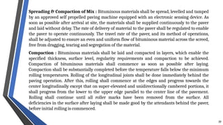
71. Spreading & Compaction of Mix : The mix may be spread by a paver finisher. The paver finisher
shall be self-propelled of adequate capacity. In exceptional cases where it is not possible for the paver
to be utilized, mechanical means like motor grader may be used with the prior approval of the
Engineer. The aggregates as spread should be of uniform gradation with no pockets of fine materials.
After the mix has been laid to the required thickness, grade and crossfall/camber the same shall be
uniformly compacted to the full depth with suitable roller. If the thickness of single compacted layer
does not exceed 100 mm, a smooth wheel roller of 80 to 100kN weight may be used. For a compacted
single layer up to 200 mm, the compaction shall be done with the help of vibratory roller of
minimum static weight of 80 to 100kN. The speed of the roller shall not exceed 5 km/h.
In portions having unidirectional cross fall/super-elevation, rolling shall commence from the lower
edge and progress gradually towards the upper edge. Thereafter, roller should progress parallel to the
center line of the road, uniformly over-lapping each preceding track by at least one-third width until
the entire surface has been rolled. Alternate trips of the roller shall be terminated in stops at least 1 m
away from any preceding stop.
If irregularities develop during rolling which exceed 12 mm when tested with a 3 m straight edge, the
surface should be loosened and premixed material added or removed as required before rolling again
so as to achieve a uniform surface conforming to the desired grade and crossfall. Rolling shall be
continued till the density achieved is at least 98 percent of the maximum dry density for the
determined material.
71
72. SECTION: 502- PRIME COAT
• Applied on Granular Surface
• Single Coat – Low Viscosity Liquid Bituminous Material
• Primer –
a. Cationic Bitumen Emulsion SS1 Grade
b. Medium Curing Cutback
• Rate of spray:
• No Heating or Dilution of SS1 Bitumen is permitted at site.
• Avoid causing runoff due to excess coat. Desired penetration 8-10 mm.
72
Type of Surface Rate of Spray (Kg/Sqm)
WMM/WBM 0.7-1.0
Stabilized Soil bases/Crusher Run Macadam 0.9-1.2
73. • Applied on Bituminous Surface or
• Cement Concrete Surface
• Single Coat – Low Viscosity Liquid Bituminous Material
• Binder – Cationic Bitumen Emulsion RS1 Grade
• Temperature –
a. 20 to 70°C (Bitumen Emulsion)
b. b. 50 to 80°C (Cut Back)
• Rate of spray:
SECTION: 503- TACK COAT
Surface Rate (Kg/Sqm)
Bituminous Surface 0.20 to 0.30
Granular Surface treated with Primer 0.25 to 0.30
Cement Concrete Pavement 0.30 to 0.35
73
74. GENERAL REQUIREMENTS FOR BITUMINOUS PAVEMENT LAYERS: Bituminous pavement
courses shall be made using the materials described in the Specifications. The binder shall be
an appropriate type of bituminous material complying with the relevant Indian Standard, as
defined in the appropriate Clauses of these Specifications, or as otherwise specified herein. The
choice of binder shall be stipulated in the Contract.
Selection criteria for viscosity grade bitumen, based on highest and lowest daily mean
temperatures at a particular site, are given in Table 500-1.Selection criteria for modified
bitumen shall be in accordance with IRC:SP:53-2010.
SECTION: 500- BASES, SURFACE COURSES (BITUMINOUS)
Table 500-1 : Selection Criteria for Viscosity-Graded (VG) Paving Bitumen's
Based on Climatic Conditions
Lowest Daily Mean
Air Temperature, °c
Highest daily mean year temperature, °c
Less than 20°C 20 to 30°C More than 30°C
More than -10°C VG-10 VG-20 VG-30
-10°C or lower VG-10 VG-10 VG-20
74
75. Coarse Aggregates: The coarse aggregates shall consist of crushed rock, crushed gravel or
other hard material retained on the 2.36 mm sieve. They shall be clean, hard, durable, of cubical
shape, free from dust and soft or friable matter, organic or other deleterious matter.
Where crushed gravel is proposed for use as aggregate not less than 90 percent by weight of the
crushed material retained on the 4.75 mm sieve shall have at least two fractured Faces.
Fine Aggregates: Fine aggregates shall consist of crushed or naturally occurring material,
or a combination of the two, passing 2.36 mm sieve and retained on the 75 micron sieve.
They shall be clean, hard, durable, dry and free from dust, and soft or friable matter, organic
or other deleterious matter. Natural sand shall not be allowed in binder and wearing
courses. However, natural sand up to 50 percent of the fine aggregates may be allowed in
base courses. Fine aggregates shall have a sand equivalent value of not less than 50 when
tested in accordance with the requirement of IS:2720 (Part 37). The plasticity index of the
fraction passing 0.425 mm shall not exceed 4 when tested.
Mixing: Pre-mixed bituminous materials shall be prepared in a hot mix plant of adequate
capacity and capable of yielding a mix of proper and uniform quality with thoroughly
coated aggregates. Appropriate mixing temperatures are given in Table 500-2 of these
Specifications. The difference in temperature between the binder and aggregate shall at no
time exceed 14°C.
75
Section: 505- Dense Bituminous Macadam (DBM)
76. Table 500-2 : Mixing, Laying and Rolling Temperatures for Bituminous
Mixes (Degree Celsius)
Bitumen
Viscosity
Grade
Bitumen
Temperature
Aggregate
Temperature
Mixed Material
Temperature
Laying
Temperature
*Rolling
Temperature
VG-40 160-170 160-175 160-170 150 Min 100 Min
VG-30 150-165 150-170 150-165 140 Min 90 Min
VG-20 145-165 145-170 145-165 135 Min 85 Min
VG-10 140-160 140-165 140-160 130 Min 80 Min
*Rolling must be completed before the mat cools to these minimum temperatures.
Laying: shall not be done in below mentioned circumstances:-
i) In presence of standing water on the surface;
ii) When rain is imminent, and during rains, fog or dust storm;
iii) When the base/binder course is damp;
iv) When the air temperature on the surface on which it is to be laid is less than 10°C for
mixes with conventional bitumen and is less than 15°C for mixes with modified bitumen;
v) When the wind speed at any temperature exceeds the 40 km per hour at 2 m height.
76
77. Spreading & Compaction of Mix : Bituminous materials shall be spread, levelled and tamped
by an approved self propelled paving machine equipped with an electronic sensing device. As
soon as possible after arrival at site, the materials shall be supplied continuously to the paver
and laid without delay. The rate of delivery of material to the paver shall be regulated to enable
the paver to operate continuously. The travel rate of the paver, and its method of operations,
shall be adjusted to ensure an even and uniform flow of bituminous material across the screed,
free from dragging, tearing and segregation of the material.
Compaction : Bituminous materials shall be laid and compacted in layers, which enable the
specified thickness, surface level, regularity requirements and compaction to be achieved.
Compaction of bituminous materials shall commence as soon as possible after laying.
Compaction shall be substantially completed before the temperature falls below the minimum
rolling temperatures. Rolling of the longitudinal joints shall be done immediately behind the
paving operation. After this, rolling shall commence at the edges and progress towards the
center longitudinally except that on super-elevated and unidirectionally cambered portions, it
shall progress from the lower to the upper edge parallel to the center line of the pavement.
Rolling shall continue until all roller marks have been removed from the surface. All
deficiencies in the surface after laying shall be made good by the attendants behind the paver,
before initial rolling is commenced.
77
78. Bituminous materials shall be rolled in a longitudinal direction, with the driven rolls nearest
the paver. The roller shall first compact material adjacent to joints and then work from the
lower to the upper side of the layer, overlapping on successive passes by at least one-third of
the width of the rear roll or, in the case of a pneumatic-tyred roller, at least the nominal width
of 300 mm. In portions with super-elevated and unidirectional camber, after the edge has been
rolled, the roller shall progress from the lower to the upper edge.
Rollers should move at a speed of not more than 5 km per hour. The roller shall not be
permitted to stand on pavement which has not been fully compacted, and necessary
precautions shall be taken to prevent dropping of oil, grease, petrol! diesel or other foreign
matter on the pavement either when the rollers are operating or standing. The wheels of roller
machine shall be in good working order, to prevent the mix from adhering to the Wheels. Only
sufficient moisture to prevent adhesion between the wheels of rollers and the mix should be
used. Surplus water shall not be allowed to stand on the partially compacted pavement.
78
79. Table 500-10 : Composition of Dense Graded Bituminous Macadam
Grading 1 2
Nominal aggregate size* 37.5 mm 26.5 mm
Layer thickness 75-100 mm 50-75 mm
IS Sieve1 (mm) Cumulative % by weight of total aggregate passing
45 100
37.5 95-100 100
26.5 63-93 90-100
19 - 71-95
13.2 55-75 56-80
9.5 - -
4.75 38-54 38-54
2.36 28-42 28-42
1.18 - -
0.6 - -
0.3 7-21 7-21
0.15 - -
0.075 2-8 2-8
Bitumen content % by mass of
total mix
Min 4.0** Min 4.5**
79
80. *The nominal maximum particle size is the largest specified sieve size upon which any of the
aggregate is retained .
**Corresponds to specific gravity of aggregates being 2.7. In case aggregate have specific gravity
more than 2.7, the minimum bitumen content can be reduced proportionately. Further the region
where highest daily mean air temperature is 30∘
c or lower and lowest daily air temperature is – 10∘
c
or lower, the bitumen content may be increased by 0.5 percent. Bitumen content indicated in Table
500-10 is the minimum quantity. The quantity shall be determined in accordance with Clause 505.3.
The Fines to Bitumen (F/B) ratio by weight of total mix shall range from 0.6 to 1.2.
BITUMINOUS CONCRETE (BC) :
This work shall consist of construction of Bituminous Concrete, for use in wearing and profile
corrective courses. This work shall consist of construction in a single layer of bituminous concrete
on a previously prepared bituminous bound surface. A single layer shall be. 30 mm/40 mm/50 mm
thick. Not less than 95 percent by weight of the crushed material retained on the 4.75 mm sieve
shall have at least two fractured faces.
80
81. Table 500-17 : Composition of Bituminous Concrete Pavement Layers
Grading 1 2
Nominal aggregate size* 19 mm 13.2 mm
Layer thickness 50 mm 30-40 mm
IS Sieve1 (mm) Cumulative % by weight of total aggregate passing
45
37.5
26.5 100
19 90-100 100
13.2 59-79 90-100
9.5 52-72 70-88
4.75 35-55 53-71
2.36 28-44 42-58
1.18 20-34 34-48
0.6 15-27 26-38
0.3 10-20 18-28
0.15 5-13 12-20
0.075 2-8 4-10
Bitumen content % by mass of
total mix
Min 5.2* Min 5.4**
81
82. Note:
*The nominal maximum particle size is the largest specified sieve size up on which any of
the aggregate is retained .
**Corresponds to specific gravity of aggregate being 2.7. In case aggregate have specific
gravity more than 2.7, the minimum bitumen content can be reduced proportionately.
Further the region where highest daily mean air temperature is 30°C or lower and lowest
daily air temperature is - 10∘
c or lower, the bitumen content may be increased by
0.5 percent.
82
83. Section: 601- Dry lean cement concrete (DLC) sub-base :
The work shall consist of construction of (zero slump) dry lean concrete sub-base for cement
concrete pavement in accordance with the requirements of these specifications and in conformity
with the lines, grades and cross-sections shown on the drawings or as directed by the Engineer.
Cement: Any of the following types of cement may be used with prior approval of the Engineer:
a. Ordinary Portland Cement 43 Grade
b. Portland Slag Cement
c. Portland Pozzolana Cement
Flyash: Fly-ash up to 20 percent by weight of cementitious material (cement +flyash) may be
used along with 43/53 grade cement may be used to replace OPC cement grade 43 up to 30
percent by weight of cement. Fly-ash shall conform to 18:3812 (Part 1) and its use shall be
permitted only after ensuring that facilities exist for uniform blending through a proper
mechanical facility with automated process control like batch mix plant conforming.
SECTION: 600- CONCRETE PAVEMENT
83
84. Aggregates:
Aggregates for lean concrete shall be natural material complying with 18:383. The aggregates shall
not be alkali reactive Coarse aggregates shall comply with Clause 602.2.6.2, except that the
maximum size of the coarse aggregate shall be 26.5 mm, and aggregate gradation shall comply with
Table 600-1.
The mix shall be proportioned with a maximum aggregate cementitious material ratio of 15:1. The
water content shall be adjusted to the optimum as per Clause 601.3.2 for facilitating compaction by
rolling.
Moisture Content:
The optimum water content shall be determined and demonstrated by rolling during trial length
construction and the optimum moisture content and degree of compaction shall be got approved
from Engineer. While laying in the main work, the lean concrete shall have a moisture content
between the optimum and optimum +2 percent, keeping in view the effectiveness of compaction
achieved and to compensate for evaporation losses.
84
85. Cement Content:
The minimum cement content shall be 150 kg/cum of concrete. In case flyash is blended at site as
part replacement of cement, the quantity of flyash shall not be more than 20 percent by weight of
cementitious material and the content of OPC shall not be less than 120 kg/cum.
Concrete Strength: The average compressive strength of each consecutive group of 5 cubes made
in accordance with Clause 903.5.1.1 shall not be less than 10 MPa at 7 days. In addition, the
minimum compressive strength of any individual cube shall not be less than 7.5 MPa at 7 days.
Drainage layer: A drainage layer conforming to Clause 401 shall be laid above the subgrade before
laying the Dry Lean Concrete sub-base, as specified in the drawings and the Contract.
The Dry Lean Concrete shall be laid on the prepared granular drainage layer. The pace and
programme of the Dry Lean Concrete sub-base construction shall be matching suitably with the
programme of construction of the cement concrete pavement over it. The Dry Lean Concrete sub-
base shall be overlaid with concrete pavement only after 7 days of sub-base construction.
85
86. The batching plant shall be capable of proportioning the materials by weight, each type of material
being weighed separately. The concrete shall be transported by tipping trucks, sufficient in number
to ensure a continuous supply of material to feed the laying equipment to work at a uniform speed
and in an uninterrupted manner.
Placing: Lean concrete shall be placed by a paver with electronic sensor on the drainage layer or as
specified in the Contract. The equipment shall be capable of laying the material in one layer. The
Dry Lean Concrete shall be laid in such a way that it is at least 750 mm wider on each side than the
proposed width including paved shoulders of the concrete pavement.
Compaction: The compaction shall be carried out immediately after the material is laid and
levelled. In order to ensure thorough compaction, rolling shall be continued on the full width till
there is no further visible movement under the roller and the surface is well closed. The minimum
dry density obtained shall not be less than 98 percent of that achieved during the trial length
construction in accordance with Clause 601.7. The densities achieved at the edges i.e. 0.5 m from the
edge shall not be less than 96 percent of that achieved during the trial construction.
86
87. 87
The spreading, compacting and finishing of the lean concrete shall be carried out as rapidly as
possible and the operation shall be so arranged as to ensure that the time between the mixing
of the first batch of concrete in any transverse section of the layer and the final finishing of the
same shall not exceed 90 minutes when the temperature of concrete is between 25°C and 30°C,
and 120 minutes if less than 25°C.
Double drum smooth-wheeled vibratory rollers of minimum 80 to 100 kN static weight are
suitable for rolling dry lean concrete. Longitudinal joint in Dry Lean Concrete shall be
staggered by 300-400 mm from the longitudinal joint of concrete pavement. As soon as the lean
concrete surface is compacted, curing shall commence.
88. SECTION: 602- CEMENT CONCRETE PAVEMENT (PQC) :
The work shall consist of construction of un-reinforced, dowel jointed, plain cement concrete
pavement in accordance with the requirements of these Specifications and in conformity with the
lines, grades and cross sections shown on the drawings.
Materials:
Cement: Any of the following types of cement may be used with prior approval of the Engineer, but
preference shall be to use 43 grade or higher.
1. Ordinary Portland Cement 43 Grade
2. Portland Slag Cement
3. Portland Pozzolana Cement
Fly-ash up to 20 percent by weight of cementitious material may be used in Ordinary Portland
cement 43 and 53 Grade as part replacement of cement provided uniform blending with cement is
ensured. The Portland Pozzolana Cement produced in factory as per IS:1489-Part I shall not have
fly-ash content more than 20 percent by weight of cementitious material. Certificate from the
manufacturer to this effect shall be produced before use.
88
89. Chemical Admixtures:
Admixtures conforming to IS:9103 and IS:6925 shall be permitted to improve workability of the
concrete and/or extension of setting time, on satisfactory evidence that they will not have any
adverse effect on the properties of concrete with respect to strength, volume change, durability
and have no deleterious effect on steel bars. Silica fume conforming to a standard approved by
the Engineer may be used as an admixture in the proportion of 3 to 10 percent of cement.
Fibers may be used subject to the provision in the design/approval by the Engineer to reduce
the shrinkage cracking and post-cracking. When fibers are used, the mix shall be so designed
that the slump of concrete at paving site is 2S±15 mm.
Aggregates:
Aggregates for pavement concrete shall be natural material complying with IS:383 but with a
Los Angeles Abrasion Test value not exceeding 35 percent. The aggregates shall be free from
chert, flint, chalcedony or other Silica in a form that can react with the alkalies in the cement.
89
90. Coarse aggregates shall consist of clean, hard, strong, dense, non-porous and durable pieces of
crushed stone or crushed gravel and shall be devoid of pieces of disintegrated stone, soft, flaky,
elongated, very angular or splintery pieces. The maximum size of coarse aggregate shall not
exceed 31.5 mm for pavement concrete. No aggregate which has water absorption more than 2
percent shall be used in the concrete mix.
The fine aggregates shall consist of clean natural sand or crushed stone sand or a combination
of the two and shall conform to 18:383. Fine aggregate shall be free from soft particles, clay,
shale, loam, cemented particles, mica and organic and other foreign matter. The fine aggregates
shall have a sand equivalent value of not less than 50.
Water used for mixing and curing of concrete shall be clean and free from injurious amount of
oil, salt, acid, vegetable matter or other substances harmful to the finished concrete.
Steel for Dowels and Tie Bars: Steel shall conform to the requirements of IS:432 and IS:1786
as relevant. The dowel bars shall conform to IS:432 of Grade I. Tie bars shall be either High
yield Strength Deformed bars conforming to IS:1786 and grade of Fe 500 or plain bars
conforming to IS:432 of Grade I. The steel shall be coated with epoxy paint for protection
against corrosion.
90
91. Joint Filler Board: Synthetic Joint filler board for expansion joints shall be used only at
abutting structures like bridges and shall be of 20-25 mm thickness within a tolerance of ± 1.5
mm and of a firm compressible material and complying with the requirements of IS:1838, with
a compressibility more than 25 percent. It shall be 25 mm less in depth than the thickness of
the slab within a tolerance of ± 3 mm and provided to the full width between the side forms.
Joint Sealing Compound: The joint sealing compound shall be of hot poured, elastomeric
type or cold polysulphide/ polyurethene/silicone type having flexibility, resistance to age
hardening and durability as per IRC:57.
If sealant is of hot poured type, it shall conform to
Hot applied sealant: IS:1834 or ASTM : 3406-95, as applicable
Cold poured sealants shall be one of the following:
i) polysulphide IS:11433 (Part I), BS:5212 (Part II)
ii) polyurethane BS:5212
iii) silicone ASTM 5893-04
91
92. Proportioning of Concrete:
After approval by the Engineer of all the materials to be used in the concrete, the Contractor shall
submit the mix design based on weighed proportions of all ingredients for the approval of the
Engineer vide Clause 602.3.4. The mix design shall be submitted at least 30 days prior to the paving
of trial length and the design shall be based on laboratory trial mixes using the approved materials
and methods. The mix design shall be based on the flexural strength of concrete.
Cement Content:
When Ordinary Portland Cement (OPC) is used the quantity of cement shall not be less than 360
kg/cum. In case flyash grade I (as per IS:3812) is blended at site as part replacement of cement, the
quantity of flyash shall be upto 20 percent by weight of cementitious material and the quantity of
OPC in such a blend shall not be less than 310 kg/cum. The minimum of OPC content, in case
ground granulated blast furnace slag cement blended, shall also not be less than 310 kg/m3.
92
93. Concrete Strength: The characteristic flexural strength of concrete shall not be less than 4.5 Mpa
unless specified otherwise. Target mean flexural strength for mix design shall be more than 4.5 MPa +
1.65s, where s is standard deviation of flexural strength derived by conducting test on minimum 30
beams. While designing the mix in the laboratory, correlation between flexural and compressive
strengths of concrete shall be established on the basis of at least thirty tests on specimens. The water
content shall be the minimum required to provide the agreed workability for full compaction of the
concrete to the required density as determined by the trial mixes or as approved by the Engineer and the
maximum free water cement ratio shall be 0.45 when only OPC is used and 0.50 when blended cement
(Portland Pozzolana Cement or Portland Slag Cement or OPC blended with flyash or Ground Granulated
Blast Furnance Slag, at site) is used.
Workability: The workability of the concrete at the point of placing shall be adequate for the concrete
to be fully compacted and finished without undue flow. The workability requirement at the batching
and mixing plant and paving site shall be established by slump tests carried during trial paving. A slump
value in the range of 25 ± 15 mm is reasonable for paving works but this may be modified depending
upon the site requirement and got approved by the Engineer. The proportions determined as a result of
the laboratory trial mixes may be adjusted, if necessary, during the construction of the trial length.
Sub-base: The cement concrete pavement shall be laid over the sub-base constructed in accordance
with the relevant drawings and Specifications. A separation membrane shall be used between the
concrete slab and the sub-base. Separation membrane shall be impermeable PVC sheet 125 micron thick
transparent or white in colour laid flat with minimum creases. Before placing the separation membrane,
the sub-base shall be swept clean of all the extraneous materials using air compressor. The separation
membrane shall be omitted when two layers of wax-based curing compound is used. 93
94. • Joints: It shall be ensured that the required depth of cut is made from edge-to-edge of the
pavement. Transverse and longitudinal joints in the pavement and Dry Lean Concrete sub-base
shall be staggered so that they are not coincident vertically and are at least 800 to 1000 mm and
300 to 400 mm apart respectively. Sawing of joints shall be carried out with diamond studded
blades soon after the concrete has hardened to take the load of the sawing machine and crew
members without damaging the texture of the pavement.
Sawing operation could start as early as 4-8 hours after laying of concrete pavement but not later
than 8 to 12 hours depending upon the ambient temperature, wind velocity, relative humidity and
required maturity of concrete achieved for this purpose.
Transverse joints shall be contraction, construction and expansion joints constructed at the spacing
described in the drawings. Transverse joints shall be straight within the tolerances.
The contraction joints shall be placed transversely at pre-specified locations as per drawings/
design using dowel bars. These joints shall be cut as soon as the concrete has undergone initial
hardening and is hard enough to take the load of joint sawing machine without causing damage to
the slab. Contraction joints shall consist of a mechanical sawn joint groove, 3 to 5 mm wide and
one-fourth to one-third depth of the slab ± 5 mm or as stipulated in the drawings.
The expansion joint shall consist of a joint filler board and the adjacent slabs shall be
completely separated from each other by the joint filler board.
94
95. Transverse construction joint shall be placed whenever concreting is completed after a day’s
work or is suspended for more than 30 minutes.
The longitudinal joints shall be constructed by forming or by sawing as per details of the joints
shown in the drawing. The groove may be cut after the final set of the concrete. Joints should
be sawn to at least one-third the depth of the slab ±5 mm as indicated in the drawing. The joint
shall be widened subsequently to dimensions shown on the drawings.
Tie Bars: Tie bars shall be provided at the longitudinal joints as per dimensions and spacing
shown in the drawing and in accordance with Clause 602.6.6. The direction of the tie bars at
curves shall be radial in the direction of the radius. Tie bars in longitudinal joints shall be
deformed steel bars of strength 500 MPa complying with IS:1786 and in accordance with the
requirements given in this Clause. The bars shall be free from oil, dirt, loose rust and scale. Tie
bars projecting across the longitudinal joint shall be protected from corrosion for 75 mm on
each side of the joint by a protective coating of bituminous paint with the approval of the
Engineer.
95
96. Dowel Bars: Dowel bars shall be mild steel rounds in accordance with Clause 602.2.8 with
details/dimensions as indicated in the drawings and free from oil, dirt, loose rust or scale. They
shall be straight, free of irregularities and burring restricting slippage in the concrete. The
sliding ends shall be sawn or cropped cleanly with no protrusions outside the normal diameter
of the bar. Dowel bars in the contraction joints, construction joints and expansion joints shall be
covered by a thin plastic sheath. The thickness of the sheath shall not exceed 0.5 mm and shall
be tightly fitted on the bar for at least two-thirds of the length from one end for dowel bars in
contraction/construction joints and half the length plus 50 mm for expansion joints.
Weather and Seasonal Limitations: No concreting shall be done when the temperature of
the concrete reaching the paving site is above 30°C. Besides, in adverse conditions like high
temperature, low relative humidity, excessive wind velocity, imminence of rains etc., tents on
mobile trusses may be provided over the freshly laid concrete for a minimum period of 3 hours
as directed by the Engineer. To bring down the temperature, if necessary, chilled water or ice
flakes should be made use of. When the ambient temperature is more than 35°C, no concreting
shall be permitted. No concreting shall be done when the concrete temperature is below 5°C
and the temperature is further falling.
96
97. Placing of Concrete: The total time taken from the addition of the water to the mix, until the
completion of the surface finishing and texturing shall not exceed 120 minutes when concrete
temperature is less than 25°C and 90 minutes when the concrete temperature is between 25°C and
30°C. When the time between mixing and laying exceed these values, the concrete shall be rejected
and removed from the site. Tipping trucks delivering concrete shall normally not run on plastic
sheathing nor shall they run on completed slabs until after 28 days of placing the concrete. The
addition of water to the surface of the concrete to facilitate the finishing operations will not be
permitted. If considered necessary by the Engineer, the paving machine shall be provided with
approved covers. to protect the surface of the slab under construction from direct sunlight and
rain or hot wind. While the concrete is still plastic, its surface shall be textured by brush or
tines as per the instructions of the engineer in compliance with Clause 602.9.11. The surface
and edges of the slab shall be cured by the application of a sprayed liquid curing membrane in
compliance with Clause 602.9.12. After the surface texturing, but before the curing compound
is applied, the concrete slab shall be marked with the chainage at every 100 m interval by
embossing.
97
98. Surface Texture: After final floating and finishing of the slab and before application of the
liquid curing membrane, the surface of concrete slabs shall be textured either in the transverse
direction (i.e., at right angles to the longitudinal axis of the road) or in longitudinal direction
(i.e., parallel to the Centre line of the roadway). The texturing shall be done by tining the
finished concrete surface by using rectangular steel tines. A beam or a bridge mounted with
steel tines shall be equipped and operated with automatic sensing and control devices from
main paver or auxiliary unit. The tining unit shall have facility for adjustment of the download
pressure on the tines as necessary to produce the desired finish. Tined grooves shall be 3 mm
wide and 3 to 4 mm deep. The Centre to Centre spacing between the tines shall be 18 to 21 mm.
Before commencing texturing, the bleeding water, if any, shall be removed. Texturing shall be
done at the right time such that the grooves after forming shall not close and they shall not get
roughened. Swerving of groove patterns will not be permitted. The completed textured surface
shall be uniform in appearance.
98
99. 99
Brush Texturing: The tufts shall contain an average of 14 wires and initially be 100 mm long.
The brush shall have two rows of tufts. The rows shall be 20 mm apart and the tufts in one row
shall be opposite the center of the gap between tufts in the other row. The brush shall be
replaced when the shortest tuft wears down to 90 mm long.
Curing: Immediately after the surface texturing, the surface and sides of the slab shall be
cured by the application of approved resin-based aluminized reflective curing compound
which hardens into an impervious film or membrane with the help of mechanical sprayer.
In addition to spraying of curing compound, the fresh concrete surface shall be protected for at
least 3 hours by covering the finished concrete pavement.
Strength: Minimum of thirty (30) beams for flexural strength and thirty (30) cubes for
compressive strength shall be prepared from the concrete delivered in front of the paving
plant. Each pair of beams and cubes shall be from the same location/batch but different sets of
beams and cubes shall be from different locations/batches. Compressive and flexural strength
shall be tested after 28 days water curing in the laboratory.
100. SECTION: 900-QUALITY CONTROL FOR ROAD WORKS
CONTROL OF ALIGNMENT, LEVEL AND SURFACE REGULARITY:
Horizontal alignment shall be reckoned with respect to the center line of the carriageway as shown on
the drawings. The edges of the carriageway as constructed shall be correct within a tolerance of ± 10 mm
therefrom. The corresponding tolerance for edges of the roadway and lower layers of pavement shall be
± 25 mm.
The levels of the subgrade and different pavement courses as constructed, shall not vary from
those calculated with reference to the longitudinal and cross-profile of the road.
Table 900-1 : Tolerances in Surface Levels
1) Subgrade ±20mm
2) Sub-base
a) Flexible pavement (GSB+WMM)
b) Concrete pavement (DLC)
±10mm
+6mm
3) Base-course for flexible pavement
a) Bituminous Base/Binder course (DBM)
b) Granular (GSB+WMM)
i) Machine laid
ii) Manually laid
±6mm
±10 mm
±15mm
4) Wearing course for flexible pavement
a) Machine laid (BC)
b) Manually laid
±6mm
±10 mm
5) Cement concrete pavement (PQC) ±5mm
100
101. For checking compliance with the above requirement for subgrade, sub-base and base course,
measurements of the surface levels shall be taken on a grid of points placed at 6.25 m
longitudinally and 3.5 m transversely. For any 10 consecutive measurements taken longitudinally
or transversely, not more than one measurement shall be permitted to exceed the tolerance as
above, this one measurement being not in excess of 5 mm above the permitted tolerance.
For checking the compliance with the above requirement for bituminous wearing
courses and concrete pavements, measurements of the surface levels shall be taken on a grid
of points spaced at 6.25 m along the length and at 0.5 m from the edges and at the center of
the pavement. Straight edge, Wedge, Spirit level are required to solve this problem.
The longitudinal profile shall be checked with a 3 metre long straight edge/moving
straightedge as directed by the Engineer at the middle of each traffic lane along a line
parallel to the center line of the road.
The riding quality of bituminous concrete wearing surface, as measured by a standard towed
fifth wheel bump integrator, shall not be more than 2000 mm per Km.
101
102. TESTS ON COMPLETION
The Concessionaire/Contractor shall, no later than 30 (thirty) days prior to the likely
completion of the Project, notify the Authority's Engineer/ Independent Engineer and the
Authority of its intent to subject the Project of Tests, and no later than 7/10 days prior to the
actual date of Tests, furnish to the Authority's Engineer/Independent Engineer and the Authority
detailed inventory and particulars of all works and equipment forming part of the Project.
In pursuance of the provision of Clause of this Agreement, the Authority's Engineer/
Independent Engineer shall conduct, or cause to be conducted, the Tests specified in this
Paragraph. The Tests may be as below:-
• Visual & physical test
• Test drive
• Riding quality test
• Pavement composition Test
• Cross-Section Test
• Structural Test for bridges
• Other tests like:- Environmental Audit , Safety Audit
102
103. TESTS ON COMPLETION
• Agency for conducting Tests:-
All test set forth in this schedule shall be conducted by the Independent
Engineer/Authority’s Engineer or such other agency or person as it may specify in
consultation with the Authority.
• Completion /Provisional Certificate:-
Upon successful completion of Tests, the Independent Engineer/Authority’s Engineer
shall issue the Completion Certificate or the Provisional Certificate, as the case may be, in
accordance with the provisions of the Article.
• Tests during construction:-
Without prejudice to the provisions of the Schedule, Tests during construction shall be
conducted in accordance with provisions of clause.
103
104. ABBREVIATION AND SYMBOLS
All the abbreviations and symbols are explained in the guidelines wherever they
appeared first in the document. Some of the abbreviations and symbols are listed below:-
AASHO - American Association of State Highway Officials
AASHTO- American Association of State Highway and Transportation Officials
ASTM - American Society of Testing and Materials
AUSTROADS- Association of Australian and New Zealand Road Transport and
Traffic Authorities
BBD - Benkelman Beam Deflection
BC - Bituminous Concrete
BIS - Bureau of Indian Standards
BM - Bituminous Macadam
BUC - Bottom-Up Cracking
CBR - California Bearing Ratio
104
105. ABBREVIATION AND SYMBOLS
CFD - Cumulative Fatigue Damage
csa - Cumulative standard axles
CTB/CT - Cement Treated Base (including all types of cement and
chemical stabilized basis)
CTSB - Cement Treated sub base (including all types of cement and
chemical stabilized basis)
CVPD - Commercial vehicle per day
DBM - Dense Bituminous Macadam
DLC - Dry Lean Concrete
FWD - Falling Weight Deflectometer
GB - Granular Base
GDP - Gross Domestic Product
GGRB - Gap Graded mix with Rubberized Bitumen
105
106. ABBREVIATION AND SYMBOLS
GSB - Granular Sub-base
IRC - Indian Roads Congress
IS - Indian Standard
ITS - Indirect Tensile Strength
kN - Kilo-Newton
mm - milli-meter
MoRTH - Ministry of Road Transport & Highways
MPa - Mega Pascal
NHAI - National Highway Authority of India
RAP - Reclaimed Asphalt Pavement
RF - Reliability Factor
SAMI - Stress Absorbing Membrane Interlayer
106
107. SDBC - Semi-Dense Bituminous Concrete
SMA - Stone Matrix Asphalt
SP - Special Publication
SS2 - Slow Setting-2 emulsion
TD - Temperature Differential
TDC - Top-Down Cracking
UCS - Unconfined Compressive Strength
VDF - Vehicle Damage Factor
WBM - Water Bound Macadam
WMM - Wet Mix Macadam
°C - degree Celsius
ABBREVIATION AND SYMBOLS
107
108. Thanks to our Director and CEO “Mr. Devendra Jain Sir”
for providing the opportunity to get this prepared.
THANKS TO ALL OF YOU FOR BEING WITH US.
DILIP BUILDCON LIMITED, BHOPAL
September-2019


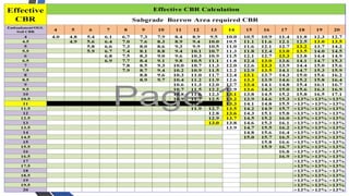


![• Dry mass density : it is defined as mass of solids per unit total volume. The solids may
shrink during drying therefore the total volume is measured before drying.
• Saturated mass density : It is the bulk mass density of the soil when the soil is in fully
saturated condition.
• Submerged mass density : It is the mass density of the soil when it is in submerged
condition. As all of us know that volume of a soil in submerged condition displaces an equal
volume of water (Archimedes principle) thus the net mass of soil in submerged condition is
reduced.
• VOLUME WEIGHT RELATIONSHIPS : These relationships are in terms of unit weight. Just
on the lines of volume mass relationships which we have studied in the previous article,
there are five types of unit weights used in soil mechanics. [The only difference in bulk mass
density and unit weight is that of mass and weight respectively] Unit weight is also known
as specific weight.
• Bulk unit weight -It is defined as the total weight per unit total volume. It is also known as
total unit weight or wet unit weight. It is expressed in the units of N/m3
or KN/m3
• Dry unit weight - It is defined as weight of solids per unit total volume.
54](https://image.slidesharecdn.com/civilengineeringpracticesbysh-250727070723-ef49d156/85/Civil-Engineering-Practices_BY-Sh-JP-Mishra-23-09-pptx-54-320.jpg)