SlideShare a Scribd company logo
CSEN1051 - Digital Logic Circuits
UNIT – IV
COMBINATIONAL LOGIC
CIRCUITS
1
Syllabus
Design procedures,
Adders, Subtractors,
Multiplexers, Demultiplexers,
Encoders, Decoders, Priority encoder,
Code converters, seven segment display,
Magnitude comparator,
Decimal adder (BCD adder),
Binary Multiplier
2
Combinational Logic
• Logic circuits for digital systems may be combinational or sequential.
• A combinational circuit consists of input variables, logic gates, and
output variables.
• The logic circuit whose outputs at any instant of time entirely depend
upon the input signals present at that time are known as combinational
circuits. Hence a combinational circuit does not contain memory
elements.
3
BASIC LOGIC BLOCK - GATE
Types of Basic Logic Blocks
- Combinational Logic Block
Logic Blocks whose output logic value depends only on the input logic
values
- Sequential Logic Block
Logic Blocks whose output logic value depends on the input values and the
state (stored information) of the blocks
Functions of Gates can be described by
- Truth Table
- Boolean Function
.
.
Gate
.
Binary
Digital
Input
Signal
Binary
Digital
Output
Signal
COMBINATIONAL GATES
A
X X = (A + B)’
B
Name Symbol Function Truth Table
AND
A X = A • B
X or
B X = AB
0 0 0
0 1 0
1 0 0
1 1 1
0 0 0
0 1 1
1 0 1
1 1 1
OR
A
X X = A + B
B
I A X X = A’
0 1
1 0
Buffer A X X = A
A X
0 0
1 1
NAND
A
X X = (AB)’
B
0 0 1
0 1 1
1 0 1
1 1 0
NOR
0 0 1
0 1 0
1 0 0
1 1 0
XOR
Exclusive OR
A X = A  B
X or
B X = A’B + AB’
0 0 0
0 1 1
1 0 1
1 1 0
A X = (A  B)’
X or
B X = A’B’+ AB
0 0 1
0 1 0
1 0 0
1 1 1
XNOR
Exclusive NOR
or Equivalence
A B X
A B X
A X
A B X
A B X
A B X
A B X
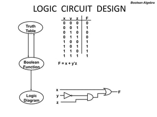
LOGIC CIRCUIT DESIGN
x y z F
0 0 0 0
0 0 1 1
0 1 0 0
0 1 1 0
1 0 0 1
1 0 1 1
1 1 0 1
1 1 1 1
F = x + y’z
Boolean Algebra
x
y
z
F
Truth
Table
Boolean
Function
Logic
Diagram
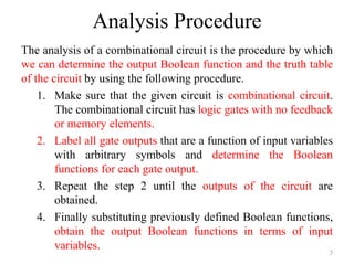
Analysis Procedure
The analysis of a combinational circuit is the procedure by which
we can determine the output Boolean function and the truth table
of the circuit by using the following procedure.
1. Make sure that the given circuit is combinational circuit.
The combinational circuit has logic gates with no feedback
or memory elements.
2. Label all gate outputs that are a function of input variables
with arbitrary symbols and determine the Boolean
functions for each gate output.
3. Repeat the step 2 until the outputs of the circuit are
obtained.
4. Finally substituting previously defined Boolean functions,
obtain the output Boolean functions in terms of input
variables.
7
Example
F2 = AB + AC + BC; T1 = A + B + C; T2 = ABC; T3
= F2’T1;
F1 = T3 + T2
F1 = T3 + T2 = F2’T1 + ABC = A’BC’ + A’B’C + AB’C’ + ABC 8
Derive truth table from logic diagram
• We can derive the truth table in Table 4-1 by using the
circuit of Fig.4-2.
9
4-3. Design procedure
1. Table4-2 is a Code-Conversion example, first, we can
list the relation of the BCD and Excess-3 codes in the
truth table.
10
Karnaugh map
2. For each symbol of the Excess-3 code, we use 1’s to
draw the map for simplifying Boolean function.
11
Circuit implementation
z = D’; y = CD + C’D’ = CD + (C + D)’
x = B’C + B’D + BC’D’ = B’(C + D) + B(C + D)’
w = A + BC + BD = A + B(C + D)
12
4-4. Binary Adder-Subtractor
• A combinational circuit that performs the addition of two bits is
called a half adder.
• The truth table for the half adder is listed below:
S = x’y + xy’
C = xy
13
S: Sum
C: Carry
Implementation of Half-Adder
14
Full-Adder
• One that performs the addition of three bits(two
significant bits and a previous carry) is a full adder.
15
Simplified Expressions
S = x’y’z + x’yz’ + xy’z’ + xyz
C = xy + xz + yz
16
C
Full adder implemented in SOP
17
Another implementation
• Full-adder can also implemented with two half adders
and one OR gate (Carry Look-Ahead adder).
S = z ⊕ (x ⊕ y)
= z’(xy’ + x’y) + z(xy’ + x’y)’
= xy’z’ + x’yz’ + xyz + x’y’z
C = z(xy’ + x’y) + xy = xy’z + x’yz + xy
18
Subtractor
• A combinational circuit that performs the
subtractions of bits is called a Subtractor.
• There are two types of Subtractors.
1.Half Subtractor
2.Full Subtractor
19
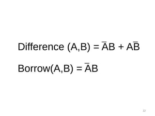
Half Subtractor:
• A combinational circuit that performs the
subtraction of two bits is called Half
Subtractor. It receives two inputs and
produces two outputs Difference and Borrow.
The block diagram of the Half Subtractor is
given as
20
• Half Subtractor Truth Table:
21
22
23
• The logical diagram for the difference can
be obtained by using the exclusive OR-
Gate.
24
Full Subtractor:
• A combinational circuit that performs the
subtraction of three bits is called a Full
Subtractor. It receives three inputs and
produces two outputs Difference and Borrow.
The Block Diagram of the Full Subtractor is as
follows.
25
Full Subtractor Block Diagram:
26
27
Simplified Boolean Function of the Full
Subtractor:
28
Simplifying the above Boolean function by
using the Karnaugh Map K.Map
29
30
• Full Subtractor Logical Diagram:
31
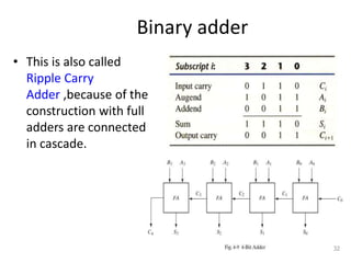
Binary adder
• This is also called
Ripple Carry
Adder ,because of the
construction with full
adders are connected
in cascade.
32
Carry Propagation
• Fig.4-9 causes a unstable factor on carry bit, and produces a
longest propagation delay.
• The signal from Ci to the output carry Ci+1, propagates through an
AND and OR gates, so, for an n-bit RCA, there are 2n gate levels
for the carry to propagate from input to output.
33
Carry Propagation
• Because the propagation delay will affect the output signals on
different time, so the signals are given enough time to get the
precise and stable outputs.
• The most widely used technique employs the principle of carry
look-ahead to improve the speed of the algorithm.
34
Boolean functions
Pi = Ai ⊕ Bi steady state value
Gi = AiBi steady state value
Output sum and carry
Si = Pi ⊕ Ci
Ci+1 = Gi + PiCi
Gi : carry generate Pi : carry propagate
C0 = input carry
C1 = G0 + P0C0
C2 = G1 + P1C1 = G1 + P1G0 + P1P0C0
C3 = G2 + P2C2 = G2 + P2G1 + P2P1G0 + P2P1P0C0
• C3 does not have to wait for C2 and C1 to propagate.
35
Logic diagram of
carry look-ahead generator
• C3 is propagated at the same time as C2 and C1.
36
4-bit adder with carry lookahead
• Delay time of n-bit CLAA = XOR + (AND + OR) + XOR
37
Binary subtractor
M = 1subtractor ; M = 0adder
38
Overflow
• It is worth noting Fig.4-13 that binary numbers in the signed-
complement system are added and subtracted by the same basic
addition and subtraction rules as unsigned numbers.
• Overflow is a problem in digital computers because the number of
bits that hold the number is finite and a result that contains n+1
bits cannot be accommodated.
39
Overflow on signed and unsigned
• When two unsigned numbers are added, an overflow is detected
from the end carry out of the MSB position.
• When two signed numbers are added, the sign bit is treated as
part of the number and the end carry does not indicate an
overflow.
• An overflow cann’t occur after an addition if one number is
positive and the other is negative.
• An overflow may occur if the two numbers added are both
positive or both negative.
40
4-5 Decimal adder
BCD adder can’t exceed 9 on each input digit. K is the carry.
41
Rules of BCD adder
• When the binary sum is greater than 1001, we obtain a non-valid
BCD representation.
• The addition of binary 6(0110) to the binary sum converts it to
the correct BCD representation and also produces an output carry
as required.
• To distinguish them from binary 1000 and 1001, which also have a
1 in position Z8, we specify further that either Z4 or Z2 must have a
1.
C = K + Z8Z4 + Z8Z2
42
Implementation of BCD adder
• A decimal parallel
adder that adds n
decimal digits needs n
BCD adder stages.
• The output carry from
one stage must be
connected to the
input carry of the next
higher-order stage.
43
If =1
0110
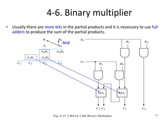
4-6. Binary multiplier
• Usually there are more bits in the partial products and it is necessary to use full
adders to produce the sum of the partial products.
44
And
4-bit by 3-bit binary multiplier
• For J multiplier bits and K
multiplicand bits we need (J X
K) AND gates and (J − 1) K-bit
adders to produce a product
of J+K bits.
• K=4 and J=3, we need 12 AND
gates and two 4-bit adders.
45
4-7. Magnitude comparator
• The equality relation of each pair
of bits can be expressed logically
with an exclusive-NOR function as:
A = A3A2A1A0 ; B = B3B2B1B0
xi=AiBi+Ai’Bi’ for i = 0, 1, 2, 3
(A = B) = x3x2x1x0
46
Magnitude comparator
• We inspect the relative magnitudes
of pairs of MSB. If equal, we
compare the next lower significant
pair of digits until a pair of unequal
digits is reached.
• If the corresponding digit of A is 1
and that of B is 0, we conclude that
A>B.
(A>B)=
A3B’3+x3A2B’2+x3x2A1B’1+x3x2x1A0B’0
(A<B)=
A’3B3+x3A’2B2+x3x2A’1B1+x3x2x1A’0B0
47
4-8. Decoders
• The decoder is called n-to-m-line decoder, where
m≤2n
.
• the decoder is also used in conjunction with other
code converters such as a BCD-to-seven_segment
decoder.
• 3-to-8 line decoder: For each possible input
combination, there are seven outputs that are equal
to 0 and only one that is equal to 1.
48
Implementation and truth table
49
Decoder with enable input
• Some decoders are constructed with NAND gates, it becomes
more economical to generate the decoder minterms in their
complemented form.
• As indicated by the truth table , only one output can be equal to 0
at any given time, all other outputs are equal to 1.
50
Demultiplexer
• A decoder with an enable input is referred to as a
decoder/demultiplexer.
• The truth table of demultiplexer is the same with
decoder.
51
Demultiplexer
D0
D1
D2
D3
E
A B
3-to-8 decoder with enable implement the
4-to-16 decoder
52
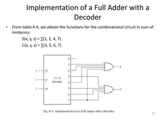
Implementation of a Full Adder with a
Decoder
• From table 4-4, we obtain the functions for the combinational circuit in sum of
minterms:
S(x, y, z) = ∑(1, 2, 4, 7)
C(x, y, z) = ∑(3, 5, 6, 7)
53
4-9. Encoders
• An encoder is the inverse operation of a decoder.
• We can derive the Boolean functions by table 4-7
z = D1 + D3 + D5 + D7
y = D2 + D3 + D6 + D7
x = D4 + D5 + D6 + D7
54
Priority encoder
• If two inputs are active simultaneously, the output produces
an undefined combination. We can establish an input priority
to ensure that only one input is encoded.
• Another ambiguity in the octal-to-binary encoder is that an
output with all 0’s is generated when all the inputs are 0; the
output is the same as when D0 is equal to 1.
• The discrepancy tables on Table 4-7 and Table 4-8 can resolve
aforesaid condition by providing one more output to indicate
that at least one input is equal to 1.
55
Priority encoder
V=0no valid inputs
V=1valid inputs
X’s in output columns represent
don’t-care conditions
X’s in the input columns are
useful for representing a truth
table in condensed form.
Instead of listing all 16
minterms of four variables.
56
4-input priority encoder
• Implementation of
table 4-8
x = D2 + D3
y = D3 + D1D’2
V = D0 + D1 + D2 + D3
57
0
0
0
0
4-10. Multiplexers
S = 0, Y = I0 Truth Table S Y Y = S’I0 + SI1
S = 1, Y = I1 0 I0
1 I1
58
4-to-1 Line Multiplexer
59
Quadruple 2-to-1 Line Multiplexer
• Multiplexer circuits can be combined with common selection inputs to provide
multiple-bit selection logic. Compare with Fig4-24.
60
I0
I1
Y
Boolean function implementation
• A more efficient method for implementing a Boolean function of
n variables with a multiplexer that has n-1 selection inputs.
F(x, y, z) = (1,2,6,7)
61
4-input function with a multiplexer
F(A, B, C, D) = (1, 3, 4, 11, 12, 13, 14, 15)
62
Three-State Gates
• A multiplexer can be constructed with three-state gates.
63
4-11. HDL for combinational circuits
• A module can be described in any one of the
following modeling techniques:
1. Gate-level modeling using instantiation of primitive gates
and user-defined modules.
2. Dataflow modeling using continuous assignment statements
with keyword assign.
3. Behavioral modeling using procedural assignment
statements with keyword always.
64
Gate-level Modeling
• A circuit is specified by its logic gates and their interconnection.
• Verilog recognizes 12 basic gates as predefined primitives.
• The logic values of each gate may be 1, 0, x(unknown), z(high-impedance).
65
Gate-level description on Verilog code
The wire declaration is for internal connections.
66
• There are two basic types of design methodologies: top-down
and bottom-up.
• Top-down: the top-level block is defined and then the sub-
blocks necessary to build the top-level block are
identified.(Fig.4-9 binary adder)
• Bottom-up: the building blocks are first identified and then
combined to build the top-level block.(Example 4-2 4-bit adder)
67
Design methodologies
A bottom-up hierarchical description
68
Full-adder
69
4-bit adder
70
Three state gates
Gates statement: gate name(output, input, control)
>> bufif1(OUT, A, control);
A = OUT when control = 1, OUT = z when control = 0;
>> notif0(Y, B, enable);
Y = B’ when enable = 0, Y = z when enable = 1;
71
2-to-1 multiplexer
• HDL uses the keyword tri to
indicate that the output has
multiple drivers.
module muxtri (A, B, select, OUT);
input A,B,select;
output OUT;
tri OUT;
bufif1 (OUT,A,select);
bufif0 (OUT,B,select);
endmodule
72
Dataflow modeling
• It uses a number of operators that act on operands to produce
desired results. Verilog HDL provides about 30 operator types.
Table 4-10
Symbol Operation
+ binary addition
− binary subtraction
& bit-wise AND
| bit-wise OR
^ bit-wise XOR
~ bit-wise NOT
== equality
> greater than
< less than
{ } concatenation
?: conditional
73
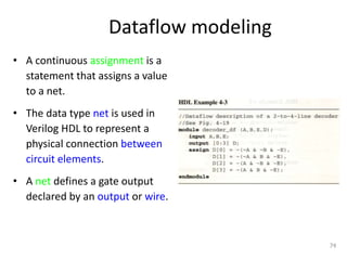
Dataflow modeling
• A continuous assignment is a
statement that assigns a value
to a net.
• The data type net is used in
Verilog HDL to represent a
physical connection between
circuit elements.
• A net defines a gate output
declared by an output or wire.
74
Dataflow description of 4-bit adder
75
HDL Example 4-4
//Dataflow description of 4-bit adder
module binary_adder (A,B,Cin,SUM,Cout);
input [3:0] A,B;
input Cin;
output [3:0] SUM;
output Cout;
assign {Cout,SUM} = A + B +Cin;
endmodule
Data flow description of a 4-bit comparator
76
Dataflow description of 2-1 multiplexer
• Conditional operator( ? : )
• Condition? true-expression : false-expression;
77
Behavioral modeling
• It is used mostly to describe sequential circuits, but can be used
also to describe combinational circuits.
• Behavioral descriptions use the keyword always followed by a list
of procedural assignment statements.
• The target output of procedural assignment statements must be
of the reg data type. Contrary to the wire data type, where the
target output of an assignment may be continuously updated, a
reg data type retains its value until a new value is assigned.
78
Behavioral description of 2-1 multiplexer
79
4-to-1-line Multiplexer
80
Writing a simple test bench
• In addition to the always statement, test benches use the initial statement to
provide stimulus to the circuit under test.
• The always statement executes repeatedly in a loop. The initial statement
executes only once starting from simulation time=0 and may continue with any
operations that are delayed by a given number of time units as specified by the
symbol #.
For example:
initial
begin
A = 0; B = 0;
#10 A = 1;
#20 A = 0; B = 1;
end
81
Stimulus and design modules interaction
• The signals of test bench as inputs to the design module are reg
data type, the outputs of design module to test bench are wire
data type.
82
Example 4-9
83
Gate Level of Verilog Code of Fig.4-2
84
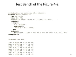
Test Bench of the Figure 4-2
85

More Related Content

What's hot (20)

PPTX
CMOS Layout
HasnafAsifIslam
 
PPTX
The BCD to excess-3 converter
Mahady Hasan
 
PDF
Ch2 la carte mère
Redouan Tourk
 
PPT
KMAP
princy75
 
PPTX
Adder & subtractor (Half adder, Full adder, Half subtractor, Full subtractor)
ISMT College
 
PPTX
Clock divide by 3
Ashok Reddy
 
PDF
Synchronous and asynchronous reset
Nallapati Anindra
 
PPTX
Unit no. 5 cmos logic design
swagatkarve
 
PPT
carry look ahead adder
ASHISH MANI
 
PPT
Verilog tutorial
Maryala Srinivas
 
PDF
Verilog VHDL code Decoder and Encoder
Bharti Airtel Ltd.
 
PPTX
PLDs
VisualBee.com
 
PPTX
halfadder & halfsubtractor using 4:1 MUX
U Reshmi
 
PPTX
8051 i o port circuit
dharmendrawaghjipur007
 
PPTX
Complex Programmable Logic Device (CPLD) Architecture and Its Applications
elprocus
 
PDF
Digital Alarm Clock 446 project report
Akash Mhankale
 
PPTX
8255 Programmable parallel I/O
Muhammed Afsal Villan
 
PDF
3. Chapter2- Storage Order - Little Endian Vs Big Endian.pdf
PIPALIYANISARG
 
PPTX
Presentation on Industrial training in VLSI
NIT Raipur
 
CMOS Layout
HasnafAsifIslam
 
The BCD to excess-3 converter
Mahady Hasan
 
Ch2 la carte mère
Redouan Tourk
 
KMAP
princy75
 
Adder & subtractor (Half adder, Full adder, Half subtractor, Full subtractor)
ISMT College
 
Clock divide by 3
Ashok Reddy
 
Synchronous and asynchronous reset
Nallapati Anindra
 
Unit no. 5 cmos logic design
swagatkarve
 
carry look ahead adder
ASHISH MANI
 
Verilog tutorial
Maryala Srinivas
 
Verilog VHDL code Decoder and Encoder
Bharti Airtel Ltd.
 
halfadder & halfsubtractor using 4:1 MUX
U Reshmi
 
8051 i o port circuit
dharmendrawaghjipur007
 
Complex Programmable Logic Device (CPLD) Architecture and Its Applications
elprocus
 
Digital Alarm Clock 446 project report
Akash Mhankale
 
8255 Programmable parallel I/O
Muhammed Afsal Villan
 
3. Chapter2- Storage Order - Little Endian Vs Big Endian.pdf
PIPALIYANISARG
 
Presentation on Industrial training in VLSI
NIT Raipur
 

Similar to combinational-circuit (1).ppt (20)

PPT
combinational-circuit (1).ppt
Krishnavenimanickam2
 
PPTX
combinational-circuit.pptx it tis creative study of digital electronics for ...
RishabhSingh308993
 
PPTX
combinational-circuit (1).pptx for all the digital electronics data
SapnaSingh529565
 
PPT
combinational-circuit presenmtation .ppt
FilibertoMoralesGarc
 
PPT
combinational-circuit.ppt
ShivamRathod34
 
PPT
combinational circuits dispositivos .ppt
FilibertoMoralesGarc
 
PPT
digital electr Chapter-4-Combinational ckt.ppt
HasanujJaman11
 
PPT
Logic System Design KTU Chapter-4.ppt
Albin562191
 
PPTX
UNIT - II.pptx
amudhak10
 
PDF
Chapter-04.pdf
ssuserf7cd2b
 
PPT
Unit 4 dica
Pavan Mukku
 
PPTX
DIGITAL ELECTRONICS :UNIT-II-COMBINATIONAL CIRCUIT DESIGN
Sridhar191373
 
PDF
Digital Electronics (EC8392) UNIT-II -PPT-S.SESHA VIDHYA/ ASP/ECE
SeshaVidhyaS
 
PDF
Combinational and sequential logic
Deepak John
 
PPT
Digital Logic Design
Vaagdevi College of Engineering
 
PPTX
DLD Lecture No 18 Analysis and Design of Combinational Circuit.pptx
SaveraAyub2
 
PPTX
Digital electronics-COMBINATIONAL CIRCUIT DESIGN
C.Helen Sulochana
 
PPTX
Digital principal and computer organization
VanithaJanarthanam2
 
PPT
5. Arithmaticn combinational Ckt.ppt
abhishekchakraborty788933
 
PPTX
Chapter 4: Combinational Logic
Er. Nawaraj Bhandari
 
combinational-circuit (1).ppt
Krishnavenimanickam2
 
combinational-circuit.pptx it tis creative study of digital electronics for ...
RishabhSingh308993
 
combinational-circuit (1).pptx for all the digital electronics data
SapnaSingh529565
 
combinational-circuit presenmtation .ppt
FilibertoMoralesGarc
 
combinational-circuit.ppt
ShivamRathod34
 
combinational circuits dispositivos .ppt
FilibertoMoralesGarc
 
digital electr Chapter-4-Combinational ckt.ppt
HasanujJaman11
 
Logic System Design KTU Chapter-4.ppt
Albin562191
 
UNIT - II.pptx
amudhak10
 
Chapter-04.pdf
ssuserf7cd2b
 
Unit 4 dica
Pavan Mukku
 
DIGITAL ELECTRONICS :UNIT-II-COMBINATIONAL CIRCUIT DESIGN
Sridhar191373
 
Digital Electronics (EC8392) UNIT-II -PPT-S.SESHA VIDHYA/ ASP/ECE
SeshaVidhyaS
 
Combinational and sequential logic
Deepak John
 
Digital Logic Design
Vaagdevi College of Engineering
 
DLD Lecture No 18 Analysis and Design of Combinational Circuit.pptx
SaveraAyub2
 
Digital electronics-COMBINATIONAL CIRCUIT DESIGN
C.Helen Sulochana
 
Digital principal and computer organization
VanithaJanarthanam2
 
5. Arithmaticn combinational Ckt.ppt
abhishekchakraborty788933
 
Chapter 4: Combinational Logic
Er. Nawaraj Bhandari
 
Ad

Recently uploaded (20)

PPTX
session2 cascading style sheet course.pptx
mostafaalgendy3
 
PDF
Top Python development services company in Bangalore
Zinavo Technologies
 
PDF
Ggggggggggggggggggggroup singing.pdf.pdf
nadifalrazi3
 
PPTX
Our Vintage Car Collection New 2023-1.pptx
ankitjhapaypal
 
PDF
The_Art_of_Interior_Design_Presentation.pdf
Royal Matrixs
 
PPTX
session2 css cascade style sheet course.pptx
mostafaalgendy3
 
PPTX
strip foundation design calculation.pptx
DemsewAdelahu
 
PPTX
Morph Slide Presentation transition.pptx
ArifaAkter10
 
PPTX
SlideEgg_300845-Electric Energy PTTTTTTT
JaydipM1
 
PPTX
Can Tho Vietnam i love my countryyy.pptx
ThMai55
 
PPTX
Artificial_Intelligence_Presentation.pptx
zyx10283746
 
PDF
CXEO CONSTRUCTION EXECUTIVE ENTREPRENEUR OWNER ACADEMY - Brand book
impybla
 
PDF
sách về ống nnnnnnnnnnnnnnnnnnnnnnnnnnnnn
nmc12345
 
PPTX
SlideEgg_500613-Natural Stones_20250715134759_Nl1PLcra (1).pptx
ChinmayRao11
 
PDF
ornament making and its material used for.pdf
departmentofcdft
 
PPT
dejjjjjjjjjjjjjjjjjjjjjjjjjjjjjjjjjsi.ppt
DenyatiSipayung
 
PDF
TAIPAN99 Situs Pkv Games Terbaik Bermain Kapan Pun Dimana Dengan Mudah #1
TAIPAN 99
 
PDF
Domestic Money Transfer(DMT) API Service Providers in India
https://dkpractice.co.in/seo.html tech
 
PPTX
(3) Protein Synthesisyghjkj Inhibitors.pptx
mkurdi133
 
PDF
Kitchen_Aluminium_Cabinet_Presentation.pdf
Royal Matrixs
 
session2 cascading style sheet course.pptx
mostafaalgendy3
 
Top Python development services company in Bangalore
Zinavo Technologies
 
Ggggggggggggggggggggroup singing.pdf.pdf
nadifalrazi3
 
Our Vintage Car Collection New 2023-1.pptx
ankitjhapaypal
 
The_Art_of_Interior_Design_Presentation.pdf
Royal Matrixs
 
session2 css cascade style sheet course.pptx
mostafaalgendy3
 
strip foundation design calculation.pptx
DemsewAdelahu
 
Morph Slide Presentation transition.pptx
ArifaAkter10
 
SlideEgg_300845-Electric Energy PTTTTTTT
JaydipM1
 
Can Tho Vietnam i love my countryyy.pptx
ThMai55
 
Artificial_Intelligence_Presentation.pptx
zyx10283746
 
CXEO CONSTRUCTION EXECUTIVE ENTREPRENEUR OWNER ACADEMY - Brand book
impybla
 
sách về ống nnnnnnnnnnnnnnnnnnnnnnnnnnnnn
nmc12345
 
SlideEgg_500613-Natural Stones_20250715134759_Nl1PLcra (1).pptx
ChinmayRao11
 
ornament making and its material used for.pdf
departmentofcdft
 
dejjjjjjjjjjjjjjjjjjjjjjjjjjjjjjjjjsi.ppt
DenyatiSipayung
 
TAIPAN99 Situs Pkv Games Terbaik Bermain Kapan Pun Dimana Dengan Mudah #1
TAIPAN 99
 
Domestic Money Transfer(DMT) API Service Providers in India
https://dkpractice.co.in/seo.html tech
 
(3) Protein Synthesisyghjkj Inhibitors.pptx
mkurdi133
 
Kitchen_Aluminium_Cabinet_Presentation.pdf
Royal Matrixs
 
Ad

combinational-circuit (1).ppt

  • 1. CSEN1051 - Digital Logic Circuits UNIT – IV COMBINATIONAL LOGIC CIRCUITS 1
  • 2. Syllabus Design procedures, Adders, Subtractors, Multiplexers, Demultiplexers, Encoders, Decoders, Priority encoder, Code converters, seven segment display, Magnitude comparator, Decimal adder (BCD adder), Binary Multiplier 2
  • 3. Combinational Logic • Logic circuits for digital systems may be combinational or sequential. • A combinational circuit consists of input variables, logic gates, and output variables. • The logic circuit whose outputs at any instant of time entirely depend upon the input signals present at that time are known as combinational circuits. Hence a combinational circuit does not contain memory elements. 3
  • 4. BASIC LOGIC BLOCK - GATE Types of Basic Logic Blocks - Combinational Logic Block Logic Blocks whose output logic value depends only on the input logic values - Sequential Logic Block Logic Blocks whose output logic value depends on the input values and the state (stored information) of the blocks Functions of Gates can be described by - Truth Table - Boolean Function . . Gate . Binary Digital Input Signal Binary Digital Output Signal
  • 5. COMBINATIONAL GATES A X X = (A + B)’ B Name Symbol Function Truth Table AND A X = A • B X or B X = AB 0 0 0 0 1 0 1 0 0 1 1 1 0 0 0 0 1 1 1 0 1 1 1 1 OR A X X = A + B B I A X X = A’ 0 1 1 0 Buffer A X X = A A X 0 0 1 1 NAND A X X = (AB)’ B 0 0 1 0 1 1 1 0 1 1 1 0 NOR 0 0 1 0 1 0 1 0 0 1 1 0 XOR Exclusive OR A X = A  B X or B X = A’B + AB’ 0 0 0 0 1 1 1 0 1 1 1 0 A X = (A  B)’ X or B X = A’B’+ AB 0 0 1 0 1 0 1 0 0 1 1 1 XNOR Exclusive NOR or Equivalence A B X A B X A X A B X A B X A B X A B X
  • 6. LOGIC CIRCUIT DESIGN x y z F 0 0 0 0 0 0 1 1 0 1 0 0 0 1 1 0 1 0 0 1 1 0 1 1 1 1 0 1 1 1 1 1 F = x + y’z Boolean Algebra x y z F Truth Table Boolean Function Logic Diagram
  • 7. Analysis Procedure The analysis of a combinational circuit is the procedure by which we can determine the output Boolean function and the truth table of the circuit by using the following procedure. 1. Make sure that the given circuit is combinational circuit. The combinational circuit has logic gates with no feedback or memory elements. 2. Label all gate outputs that are a function of input variables with arbitrary symbols and determine the Boolean functions for each gate output. 3. Repeat the step 2 until the outputs of the circuit are obtained. 4. Finally substituting previously defined Boolean functions, obtain the output Boolean functions in terms of input variables. 7
  • 8. Example F2 = AB + AC + BC; T1 = A + B + C; T2 = ABC; T3 = F2’T1; F1 = T3 + T2 F1 = T3 + T2 = F2’T1 + ABC = A’BC’ + A’B’C + AB’C’ + ABC 8
  • 9. Derive truth table from logic diagram • We can derive the truth table in Table 4-1 by using the circuit of Fig.4-2. 9
  • 10. 4-3. Design procedure 1. Table4-2 is a Code-Conversion example, first, we can list the relation of the BCD and Excess-3 codes in the truth table. 10
  • 11. Karnaugh map 2. For each symbol of the Excess-3 code, we use 1’s to draw the map for simplifying Boolean function. 11
  • 12. Circuit implementation z = D’; y = CD + C’D’ = CD + (C + D)’ x = B’C + B’D + BC’D’ = B’(C + D) + B(C + D)’ w = A + BC + BD = A + B(C + D) 12
  • 13. 4-4. Binary Adder-Subtractor • A combinational circuit that performs the addition of two bits is called a half adder. • The truth table for the half adder is listed below: S = x’y + xy’ C = xy 13 S: Sum C: Carry
  • 15. Full-Adder • One that performs the addition of three bits(two significant bits and a previous carry) is a full adder. 15
  • 16. Simplified Expressions S = x’y’z + x’yz’ + xy’z’ + xyz C = xy + xz + yz 16 C
  • 18. Another implementation • Full-adder can also implemented with two half adders and one OR gate (Carry Look-Ahead adder). S = z ⊕ (x ⊕ y) = z’(xy’ + x’y) + z(xy’ + x’y)’ = xy’z’ + x’yz’ + xyz + x’y’z C = z(xy’ + x’y) + xy = xy’z + x’yz + xy 18
  • 19. Subtractor • A combinational circuit that performs the subtractions of bits is called a Subtractor. • There are two types of Subtractors. 1.Half Subtractor 2.Full Subtractor 19
  • 20. Half Subtractor: • A combinational circuit that performs the subtraction of two bits is called Half Subtractor. It receives two inputs and produces two outputs Difference and Borrow. The block diagram of the Half Subtractor is given as 20
  • 21. • Half Subtractor Truth Table: 21
  • 22. 22
  • 23. 23
  • 24. • The logical diagram for the difference can be obtained by using the exclusive OR- Gate. 24
  • 25. Full Subtractor: • A combinational circuit that performs the subtraction of three bits is called a Full Subtractor. It receives three inputs and produces two outputs Difference and Borrow. The Block Diagram of the Full Subtractor is as follows. 25
  • 26. Full Subtractor Block Diagram: 26
  • 27. 27
  • 28. Simplified Boolean Function of the Full Subtractor: 28
  • 29. Simplifying the above Boolean function by using the Karnaugh Map K.Map 29
  • 30. 30
  • 31. • Full Subtractor Logical Diagram: 31
  • 32. Binary adder • This is also called Ripple Carry Adder ,because of the construction with full adders are connected in cascade. 32
  • 33. Carry Propagation • Fig.4-9 causes a unstable factor on carry bit, and produces a longest propagation delay. • The signal from Ci to the output carry Ci+1, propagates through an AND and OR gates, so, for an n-bit RCA, there are 2n gate levels for the carry to propagate from input to output. 33
  • 34. Carry Propagation • Because the propagation delay will affect the output signals on different time, so the signals are given enough time to get the precise and stable outputs. • The most widely used technique employs the principle of carry look-ahead to improve the speed of the algorithm. 34
  • 35. Boolean functions Pi = Ai ⊕ Bi steady state value Gi = AiBi steady state value Output sum and carry Si = Pi ⊕ Ci Ci+1 = Gi + PiCi Gi : carry generate Pi : carry propagate C0 = input carry C1 = G0 + P0C0 C2 = G1 + P1C1 = G1 + P1G0 + P1P0C0 C3 = G2 + P2C2 = G2 + P2G1 + P2P1G0 + P2P1P0C0 • C3 does not have to wait for C2 and C1 to propagate. 35
  • 36. Logic diagram of carry look-ahead generator • C3 is propagated at the same time as C2 and C1. 36
  • 37. 4-bit adder with carry lookahead • Delay time of n-bit CLAA = XOR + (AND + OR) + XOR 37
  • 38. Binary subtractor M = 1subtractor ; M = 0adder 38
  • 39. Overflow • It is worth noting Fig.4-13 that binary numbers in the signed- complement system are added and subtracted by the same basic addition and subtraction rules as unsigned numbers. • Overflow is a problem in digital computers because the number of bits that hold the number is finite and a result that contains n+1 bits cannot be accommodated. 39
  • 40. Overflow on signed and unsigned • When two unsigned numbers are added, an overflow is detected from the end carry out of the MSB position. • When two signed numbers are added, the sign bit is treated as part of the number and the end carry does not indicate an overflow. • An overflow cann’t occur after an addition if one number is positive and the other is negative. • An overflow may occur if the two numbers added are both positive or both negative. 40
  • 41. 4-5 Decimal adder BCD adder can’t exceed 9 on each input digit. K is the carry. 41
  • 42. Rules of BCD adder • When the binary sum is greater than 1001, we obtain a non-valid BCD representation. • The addition of binary 6(0110) to the binary sum converts it to the correct BCD representation and also produces an output carry as required. • To distinguish them from binary 1000 and 1001, which also have a 1 in position Z8, we specify further that either Z4 or Z2 must have a 1. C = K + Z8Z4 + Z8Z2 42
  • 43. Implementation of BCD adder • A decimal parallel adder that adds n decimal digits needs n BCD adder stages. • The output carry from one stage must be connected to the input carry of the next higher-order stage. 43 If =1 0110
  • 44. 4-6. Binary multiplier • Usually there are more bits in the partial products and it is necessary to use full adders to produce the sum of the partial products. 44 And
  • 45. 4-bit by 3-bit binary multiplier • For J multiplier bits and K multiplicand bits we need (J X K) AND gates and (J − 1) K-bit adders to produce a product of J+K bits. • K=4 and J=3, we need 12 AND gates and two 4-bit adders. 45
  • 46. 4-7. Magnitude comparator • The equality relation of each pair of bits can be expressed logically with an exclusive-NOR function as: A = A3A2A1A0 ; B = B3B2B1B0 xi=AiBi+Ai’Bi’ for i = 0, 1, 2, 3 (A = B) = x3x2x1x0 46
  • 47. Magnitude comparator • We inspect the relative magnitudes of pairs of MSB. If equal, we compare the next lower significant pair of digits until a pair of unequal digits is reached. • If the corresponding digit of A is 1 and that of B is 0, we conclude that A>B. (A>B)= A3B’3+x3A2B’2+x3x2A1B’1+x3x2x1A0B’0 (A<B)= A’3B3+x3A’2B2+x3x2A’1B1+x3x2x1A’0B0 47
  • 48. 4-8. Decoders • The decoder is called n-to-m-line decoder, where m≤2n . • the decoder is also used in conjunction with other code converters such as a BCD-to-seven_segment decoder. • 3-to-8 line decoder: For each possible input combination, there are seven outputs that are equal to 0 and only one that is equal to 1. 48
  • 50. Decoder with enable input • Some decoders are constructed with NAND gates, it becomes more economical to generate the decoder minterms in their complemented form. • As indicated by the truth table , only one output can be equal to 0 at any given time, all other outputs are equal to 1. 50
  • 51. Demultiplexer • A decoder with an enable input is referred to as a decoder/demultiplexer. • The truth table of demultiplexer is the same with decoder. 51 Demultiplexer D0 D1 D2 D3 E A B
  • 52. 3-to-8 decoder with enable implement the 4-to-16 decoder 52
  • 53. Implementation of a Full Adder with a Decoder • From table 4-4, we obtain the functions for the combinational circuit in sum of minterms: S(x, y, z) = ∑(1, 2, 4, 7) C(x, y, z) = ∑(3, 5, 6, 7) 53
  • 54. 4-9. Encoders • An encoder is the inverse operation of a decoder. • We can derive the Boolean functions by table 4-7 z = D1 + D3 + D5 + D7 y = D2 + D3 + D6 + D7 x = D4 + D5 + D6 + D7 54
  • 55. Priority encoder • If two inputs are active simultaneously, the output produces an undefined combination. We can establish an input priority to ensure that only one input is encoded. • Another ambiguity in the octal-to-binary encoder is that an output with all 0’s is generated when all the inputs are 0; the output is the same as when D0 is equal to 1. • The discrepancy tables on Table 4-7 and Table 4-8 can resolve aforesaid condition by providing one more output to indicate that at least one input is equal to 1. 55
  • 56. Priority encoder V=0no valid inputs V=1valid inputs X’s in output columns represent don’t-care conditions X’s in the input columns are useful for representing a truth table in condensed form. Instead of listing all 16 minterms of four variables. 56
  • 57. 4-input priority encoder • Implementation of table 4-8 x = D2 + D3 y = D3 + D1D’2 V = D0 + D1 + D2 + D3 57 0 0 0 0
  • 58. 4-10. Multiplexers S = 0, Y = I0 Truth Table S Y Y = S’I0 + SI1 S = 1, Y = I1 0 I0 1 I1 58
  • 60. Quadruple 2-to-1 Line Multiplexer • Multiplexer circuits can be combined with common selection inputs to provide multiple-bit selection logic. Compare with Fig4-24. 60 I0 I1 Y
  • 61. Boolean function implementation • A more efficient method for implementing a Boolean function of n variables with a multiplexer that has n-1 selection inputs. F(x, y, z) = (1,2,6,7) 61
  • 62. 4-input function with a multiplexer F(A, B, C, D) = (1, 3, 4, 11, 12, 13, 14, 15) 62
  • 63. Three-State Gates • A multiplexer can be constructed with three-state gates. 63
  • 64. 4-11. HDL for combinational circuits • A module can be described in any one of the following modeling techniques: 1. Gate-level modeling using instantiation of primitive gates and user-defined modules. 2. Dataflow modeling using continuous assignment statements with keyword assign. 3. Behavioral modeling using procedural assignment statements with keyword always. 64
  • 65. Gate-level Modeling • A circuit is specified by its logic gates and their interconnection. • Verilog recognizes 12 basic gates as predefined primitives. • The logic values of each gate may be 1, 0, x(unknown), z(high-impedance). 65
  • 66. Gate-level description on Verilog code The wire declaration is for internal connections. 66
  • 67. • There are two basic types of design methodologies: top-down and bottom-up. • Top-down: the top-level block is defined and then the sub- blocks necessary to build the top-level block are identified.(Fig.4-9 binary adder) • Bottom-up: the building blocks are first identified and then combined to build the top-level block.(Example 4-2 4-bit adder) 67 Design methodologies
  • 68. A bottom-up hierarchical description 68
  • 71. Three state gates Gates statement: gate name(output, input, control) >> bufif1(OUT, A, control); A = OUT when control = 1, OUT = z when control = 0; >> notif0(Y, B, enable); Y = B’ when enable = 0, Y = z when enable = 1; 71
  • 72. 2-to-1 multiplexer • HDL uses the keyword tri to indicate that the output has multiple drivers. module muxtri (A, B, select, OUT); input A,B,select; output OUT; tri OUT; bufif1 (OUT,A,select); bufif0 (OUT,B,select); endmodule 72
  • 73. Dataflow modeling • It uses a number of operators that act on operands to produce desired results. Verilog HDL provides about 30 operator types. Table 4-10 Symbol Operation + binary addition − binary subtraction & bit-wise AND | bit-wise OR ^ bit-wise XOR ~ bit-wise NOT == equality > greater than < less than { } concatenation ?: conditional 73
  • 74. Dataflow modeling • A continuous assignment is a statement that assigns a value to a net. • The data type net is used in Verilog HDL to represent a physical connection between circuit elements. • A net defines a gate output declared by an output or wire. 74
  • 75. Dataflow description of 4-bit adder 75 HDL Example 4-4 //Dataflow description of 4-bit adder module binary_adder (A,B,Cin,SUM,Cout); input [3:0] A,B; input Cin; output [3:0] SUM; output Cout; assign {Cout,SUM} = A + B +Cin; endmodule
  • 76. Data flow description of a 4-bit comparator 76
  • 77. Dataflow description of 2-1 multiplexer • Conditional operator( ? : ) • Condition? true-expression : false-expression; 77
  • 78. Behavioral modeling • It is used mostly to describe sequential circuits, but can be used also to describe combinational circuits. • Behavioral descriptions use the keyword always followed by a list of procedural assignment statements. • The target output of procedural assignment statements must be of the reg data type. Contrary to the wire data type, where the target output of an assignment may be continuously updated, a reg data type retains its value until a new value is assigned. 78
  • 79. Behavioral description of 2-1 multiplexer 79
  • 81. Writing a simple test bench • In addition to the always statement, test benches use the initial statement to provide stimulus to the circuit under test. • The always statement executes repeatedly in a loop. The initial statement executes only once starting from simulation time=0 and may continue with any operations that are delayed by a given number of time units as specified by the symbol #. For example: initial begin A = 0; B = 0; #10 A = 1; #20 A = 0; B = 1; end 81
  • 82. Stimulus and design modules interaction • The signals of test bench as inputs to the design module are reg data type, the outputs of design module to test bench are wire data type. 82
  • 84. Gate Level of Verilog Code of Fig.4-2 84
  • 85. Test Bench of the Figure 4-2 85