


![Distributed Coordination Function
• One of the two protocols defined by IEEE at the
MAC sublayer is called the distributed
coordination function (DCF).
• DCF uses CSMA/CA [Carrier Sense Multiple
Access/ Collision Avoidance]as the access
method.
• Wireless LANs cannot implement CSMA/CD
[Carrier Sense Multiple Access/ Collision
Detection] for three reasons:](https://image.slidesharecdn.com/mcars02temp-250227115440-33dbb018/85/Common-Network-Architecture-X-25-Networks-Ethernet-Standard-and-Fast-frame-format-and-specifications-Wireless-LAN-s-802-11x-802-3-Bluetooth-etc-98-320.jpg)


Ad
More Related Content
Similar to Common Network Architecture:X.25 Networks, Ethernet (Standard and Fast): frame format and specifications, Wireless LAN’s – 802.11x, 802.3 Bluetooth etc. (20)
Recently uploaded (20)


Ad
Common Network Architecture:X.25 Networks, Ethernet (Standard and Fast): frame format and specifications, Wireless LAN’s – 802.11x, 802.3 Bluetooth etc.
- 1. Common Network Architecture Chapter No. 2
- 2. Connection oriented Vs Connection less network Connection-Oriented means that when devices communicate, they perform handshaking to set up an end-to-end connection. In connectionless design every packet is addressed and routed independently.
- 3. Connection oriented Protocols Characteristics: 1.Handshaking (Setting up connection) between communicating devices. Connections sometimes are called as sessions, virtual circuits or logical connections. 2.Acknowledgement procedure. This provides a high level of network reliability. 3.It provides means of error control. Whenever receiving station found that received data packet consist of errors it request sender to retransmit that packet. 4.It is a uni-cast (point-to-point) operation.
- 4. •Connection-oriented •Setup data transfer ahead of time (through handshaking) •Internet’s connection-oriented service is TCP (Transmission Control Protocol). It provides : •reliable, in-order byte delivery •flow control •congestion control. •Applications using TCP: Email (SMTP), web browsing (HTTP), and file transfer (FTP)
- 5. Connectionless (Stateless) Protocols Characteristics: • It sends data with a source and destination address without a handshake. • Do not use any acknowledgment procedure. • Usually do not support error control. • Connectionless protocols are more efficient than that of connection oriented protocols. • It allows multicast and broadcast operations.
- 6. •Connectionless Internet’s connectionless service is UDP (User Datagram Protocol) . It provides unreliable data transfer no flow control no congestion control Applications using UDP: streaming media, video conferencing, and IP telephony
- 7. A comparison of Connection-Oriented and Connectionless Network
- 8. Peer-to-Peer Network • A peer-to-peer network is a distributed network architecture composed of participants that make a portion of their resources, such as processing power, disk storage or network bandwidth directly to network participants without the need for central coordination instances. • Used largely for sharing of content files such as audio, video, data or anything in a digital format. • Can be very large
- 9. • End-systems (or peers), are capable of behaving as clients and servers of data, hence system is scalable and reliable • Peers participation is voluntary, membership is dynamic, hence topology keeps changing • Most popularly used for file sharing, hence peer- to-peer systems have become synonymous with peer-to-peer file sharing networks Peer-to-Peer Network
- 10. A Peer • Peers are both suppliers and consumers while in the traditional client-server model, the server supplies while the client only consumes.
- 12. Advantages • The more nodes that are part of the system, demand increases and total capacity of the system also increases. Where in client-server network architectures as more clients are added to the system, the system resources decreases. • There is no single point of failure, due to robustness of the system. • All clients provide to the system
- 13. Disadvantages • Security is a major concern, not all shared files are from beginning sources. Attackers may add malware to p2p files as an attempt to take control of other nodes in the network. • Heavy bandwidth usage • ISP speeding/slowing of P2P traffic. • Potential legal/moral concerns
- 14. CO Vs. CL • In connection oriented service authentication is needed while connectionless service does not need any authentication. • Connection oriented protocol makes a connection and checks whether message is received or not and sends again if an error occurs connectionless service protocol does not guarantees a delivery. • Connection oriented service is more reliable than connectionless service. • Connection oriented service interface is stream based and connectionless is message based.
- 15. Service Primitives • A service is specified by a set of primitives. A primitive means operation. To access the service a user process can access these primitives. • These primitives are different for connection oriented service and connectionless service.
- 16. • LISTEN : When a server is ready to accept an incoming connection it executes the LISTEN primitive. It blocks waiting for an incoming connection. • CONNECT : It connects the server by establishing a connection. Response is awaited. • RECIEVE: Then the RECIEVE call blocks the server. • SEND : Then the client executes SEND primitive to transmit its request followed by the execution of RECIEVE to get the reply. Send the message. • DISCONNECT : This primitive is used for terminating the connection. After this primitive one can’t send any message. When the client sends DISCONNECT packet then the server also sends the DISCONNECT packet to acknowledge the client. When the server package is received by client then the process is terminated. Connection Oriented Service Primitives
- 17. Primitives for Connectionless Oriented Service • UNIDATA - This primitive sends a packet of data • FACILITY, REPORT - Primitive for enquiring about the performance of the network, like delivery statistics.
- 18. CO Vs. CL • In connection oriented service authentication is needed while connectionless service does not need any authentication. • Connection oriented service is more reliable than connectionless service. • Connection oriented service interface is stream (01 format) based and connectionless is message based.
- 19. X.25 Networks • X.25 is a standard used by many older public networks specially outside the U.S. • The packet switching networks use X.25 protocol . • X.25 was developed for computer connections, used for terminal/timesharing connection.
- 20. X.25 Networks • A protocol X.21 which is a physical layer protocol is used to specify the physical electrical and procedural interface between the host and network.
- 21. • It allows the user to establish virtual circuits and send packets on them. These packets are delivered to the destination reliably and in order. • X.25 is a connection oriented service. • It supports switched virtual circuits as well as the permanent circuits.
- 22. • Packets can then be sent over this connection from sender to receiver. • X.25 provides the flow control, to avoid a fast sender overriding a slow or busy receiver.
- 23. • A permanent virtual circuit is analogous to-a leased line. It is set up in advance with a mutual agreement between the users. • Since it is always present, no call set up is required for its use.
- 24. • X.25 Most widely used today • X.25 is an interface between DTE ( Data Terminal Equipment) and DCE (Data Communication Equipment) for terminal operation at the packet mode on public data network. – A packet switching protocol used in WAN.
- 25. • DTE is typically either a dumb terminal or the serial port on a computer/workstation. • DCE is typically a modem, or other piece of data communications equipment, hence the names.
- 26. Three Layers of X.25 The X.25 interface is defined at three levels: The three levels are: (i) Physical layer (level 1) (ii) Data link layer (level 2) (iii) Packet layer (level 3).
- 27. • Layers
- 28. PLP packet
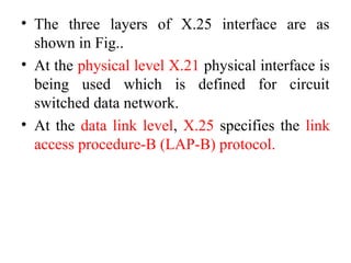
- 29. • The three layers of X.25 interface are as shown in Fig.. • At the physical level X.21 physical interface is being used which is defined for circuit switched data network. • At the data link level, X.25 specifies the link access procedure-B (LAP-B) protocol.
- 31. • At the network level (3rd level), X.25 defines a protocol for an access to packet data subnetwork. • This protocol defines the format, content and procedures for exchange of control and data transfer packets. The packet layer provides an external virtual circuit service. • Next Fig. shows the relationship between the levels of X.25. User data is passed down to X.25 level 3. • ---------------------
- 33. • The entire X.25 packet formed at the packet level is then passed down to the second layer i.e. the data link layer. • Information packets and Control packets formed at packet level and passed to LAP-B frame. • This frame is then passed to the physical layer for transmission.
- 34. Packet Layer Protocol • PLP packets : Information packets and Control packets • Information Packets (I-packets) – transmit user data – consists of a header and a user data field – The last bit in the header = 0 for I-packets
- 35. Packet Layer Protocol • I-packet fields – General format identifier (GFI) field: 4 bits • Q bit : not defined in the standard. Users define two types of data. • D bit: for packet sequencing. – Virtual circuit identification (VCI) fields • Logical channel group number (LCGN) : 4 bits • Logical channel number (LCN) : 8 bits • total 12 bits to identify the virtual circuit for a transmission
- 36. Packet Layer Protocol • I-packet fields • P(S) and P(R) : packet sequence numbers for flow and error control • P(S) for packet send, P(R) for packet receive
- 37. Packet Layer Protocol • Control Packets (C-packets) ~ flow and error control ~ connection, termination and management control – Category I (for flow and error control) • RR: Receive Ready - the station is ready to receive more packets • RNR: Receive Not Ready • REJ: Reject - an error in the packet (go-back-n ARQ)
- 38. Packet Layer Protocol • Control Packet (C-packet) – Category II • for connection, termination and management control • control packet types
- 39. Control Packets • Category II – Call Request/Incoming Call • request the establishment of a connection between two DTEs – Call Accepted/Call Connected • indicate the acceptance of the requested connection by the called system
- 40. Control Packets • Category II (cont’d) – Clear Request/Clear Indication • to disconnect the connection at the end of an exchange – Clear Confirm • sent in response to the clear indication – and More...
- 41. Virtual Circuit Service • With the X.25 packet layer, data are transmitted in packets over external virtual circuits, The virtual circuit service of X.25 provides for two types of virtual circuits. • The virtual circuit service of X.25 provides for two types of virtual circuits i.e. "virtual call" and "permanent virtual circuit".
- 42. Virtual Circuit Service • A virtual call is a dynamically established virtual circuit using a call set up and call clearing procedure. • A permanent virtual circuit is a fixed, network assigned virtual circuit. Data transfer takes place as with virtual calls, but no call set up or clearing is required.
- 43. Characteristics of X.25 • Multiple logical channels can be set on a single physical line. • Terminals of different communication speeds can communicate.
- 44. Wired LANs: Ethernet . •The LAN market has several technologies such as Ethernet, Token Ring, Token Bus and ATM LAN. • Ethernet is dominant technology.
- 45. IEEE STANDARDS •Computer Society of the IEEE started a project, called Project 802, to set standards to enable intercommunication among equipment from a variety of manufacturers. •Project 802 is a way of specifying functions of the physical layer and the data link layer of major LAN protocols.
- 46. •The relationship of the 802 Standard to the traditional OSI(open source interconnection) model is shown in Figure . •The IEEE has subdivided the data link layer into two sub layers: logical link control (LLC) Media Access Control (MAC). •IEEE has also created several physical layer standards for different LAN protocols.
- 47. Figure : IEEE standards for LANs
- 48. Data Link Layer: •Data link control handles framing, flow control, and error control. •In IEEE Project 802, flow control, error control, and part of the framing duties are collected into one sub layer called the logical link control. •Framing is handled in both the LLC sub layer and the MAC sub layer.
- 49. Data Link Layer: •The LLC provides one single data link control protocol for all IEEE LANs. •The purpose of the LLC is to provide flow and error control for the upper-layer protocols(like Network layers etc.) that actually demand these services.
- 50. Data Link Layer: •IEEE Project 802 has created a sub layer called Media Access Control (MAC) that defines the specific access method for each LAN. •For example, it defines the token passing method for both Token Ring and Token Bus LANs.
- 51. STANDARD ETHERNET • It has gone through four generations: Standard Ethernet (10+ Mbps), Fast Ethernet (100 Mbps), Gigabit Ethernet (l Gbps), and Ten- Gigabit Ethernet (10 Gbps), as shown in Figure.
- 52. Media Access Control (MAC) Sublayer • Frame Format : The Ethernet frame contains seven fields: preamble, SFD, DA, SA, length or type of protocol data unit (PDU), upper-layer data, and the CRC. • Ethernet does not provide any mechanism for acknowledging received frames, making it what is known as an unreliable medium.
- 53. 802.3 MAC frame • Preamble: The first field of the 802.3 frame contains 7 bytes (56 bits) of alternating 0s and 1s that alerts the receiving system to the coming frame and enables it to synchronize its input timing. • The pattern provides only an alert and a timing pulse.
- 54. 802.3 MAC FRAME START FRAME DELIMITER (SFD). • The second field (1 byte: 10101011) signals the beginning of the frame.
- 55. DESTINATION ADDRESS (DA) •The DA field is 6 bytes and contains the physical address of the destination station or stations to receive the packet. SOURCE ADDRESS (SA) •The SA field is also 6 bytes and contains the physical address of the sender of the packet.
- 56. LENGTH OR TYPE. •This field is defined as a type field or length field. DATA. •This field carries data encapsulated from the upper- layer protocols. It is a minimum of 46 and a maximum of 1500 bytes. CRC. •The last field contains error detection information, in this case a CRC-32
- 57. Frame Length • Ethernet has imposed restrictions on both the minimum and maximum lengths of a frame, as shown in Figure.
- 58. ADDRESSING • Each station on an Ethernet network (such as a PC, workstation, or printer) has its own network interface card (NIC). • The NIC fits inside the station and provides the station with a 6-byte physical address. As shown in Figure, the Ethernet address is 6 bytes (48 bits), normally written in hexadecimal notation, with a colon between the bytes. Example of an Ethernet address in hexadecimal notation
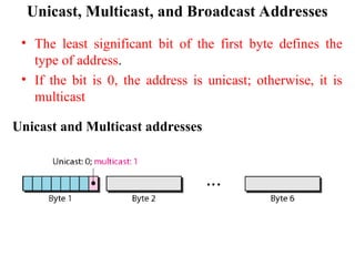
- 59. Unicast, Multicast, and Broadcast Addresses • A source address is always a unicast address-the frame comes from only one station. • The destination address, however, can be unicast, multicast, or broadcast. • Figure shows how to distinguish a unicast address from a multicast address.
- 60. Unicast, Multicast, and Broadcast Addresses • The least significant bit of the first byte defines the type of address. • If the bit is 0, the address is unicast; otherwise, it is multicast Unicast and Multicast addresses
- 61. • A unicast destination address defines only one recipient; the relationship between the sender and the receiver is one-to-one. • A multicast destination address defines a group of addresses; the relationship between the sender and the receivers is one-to-many.
- 62. • The broadcast address is a special case of the multicast address; the recipients are all the stations on the LAN. A broadcast destination address is forty-eight 1s. • The broadcast destination address is a special case of the multicast address in which all bits are 1s.
- 63. Examples 5=23 +22 +21 +20 =4+1= 5= 0101 A-10, B-11, C-12,D-13,E-14,F-15
- 64. Categories of Standard Ethernet
- 65. 1OBase5: Thick Ethernet • The first implementation is called 10Base5, thick Ethernet, or Thicknet. • 1OBase5 was the first Ethernet specification to use a bus topology with an external transceiver (transmitter/receiver) connected via a tap to a thick coaxial cable. • Figure shows a schematic diagram of a 1OBase5 implementation.
- 66. 1OBase5: Thick Ethernet 1OBase5 implementation
- 67. • The transceiver is responsible for transmitting, receiving, and detecting collisions. • The transceiver is connected to the station via a transceiver cable that provides separate paths for sending and receiving. This means that collision can only happen in the coaxial cable. • The maximum length of the coaxial cable must not exceed 500 m, otherwise, there is excessive degradation of the signal.
- 68. 10Base2: Thin Ethernet • The second implementation is called 1OBase2, thin Ethernet, or Cheapernet. • 1OBase2 also uses a bus topology, but the cable is much thinner and more flexible. The cable can be bent to pass very close to the stations. • In this case, the transceiver is normally part of the network interface card (NIC), which is installed inside the station. Figure shows the schematic diagram of a 1OBase2 implementation.
- 70. • Collision here occurs in the thin coaxial cable. This implementation is more cost effective than 10Base5 because thin coaxial cable is less expensive than thick coaxial and the tee connections are much cheaper than taps. • Installation is simpler because the thin coaxial cable is very flexible. However, the length of each segment cannot exceed 185 m .
- 71. 1OBase-T: Twisted-Pair Ethernet • The third implementation is called 1OBase-T or twisted-pair Ethernet. 1OBase-T uses a physical star topology. The stations are connected to a hub via two pairs of twisted cable, as shown in Figure.
- 72. • Note that two pairs of twisted cable create two paths (one for sending and one for receiving) between the station and the hub. • Any collision here happens in the hub. • Compared to 1OBase5 or 1OBase2, we can see that the hub actually replaces the coaxial cable as far as a collision is concerned. • The maximum length of the twisted cable here is 100 m.
- 73. 1OBase-F: Fiber Ethernet • Although there are several types of optical fiber 1O-Mbps Ethernet, the most common is called 10Base-F. 1OBase-F uses a star topology to connect stations to a hub. The stations are connected to the hub using two fiber-optic cables, as shown in Figure.
- 74. Summary of Standard Ethernet implementations
- 75. CHANGES IN THE STANDARD • The 10-Mbps Standard Ethernet has gone through several changes before moving to the higher data rates. • These changes actually opened the road to the evolution of the Ethernet to become compatible with other high-data-rate LANs.
- 76. BRIDGED ETHERNET • Bridges have two effects on an Ethernet LAN: – They raise the bandwidth – they separate collision domains. • In an unbridged Ethernet network, the total capacity (10 Mbps) is shared among all stations with a frame to send; the stations share the bandwidth of the network. • If only one station has frames to send, it benefits from the total capacity (10 Mbps). But if more than one station needs to use the network, the capacity is shared. • A bridge divides the network into two or more networks. Bandwidth-wise, each network is independent.
- 77. A network with and without a bridge •Another advantage of a bridge is the separation of the collision domain. • In Bridge the collision domain becomes much smaller and the probability of collision is reduced .
- 78. A network with and without a bridge
- 79. Switched Ethernet • If we can have a multiple-port bridge, why not have an N-port switch? In this way, the bandwidth is shared only between the station and the switch (5 Mbps each). In addition, the collision domain is divided into N domains. • A layer 2 ( Data Link Layer) switch is an N- port bridge with additional sophistication that allows faster handling of the packets. • Combination of a bridged Ethernet to a switched Ethernet gives faster Ethernet. Figure shows a switched LAN.
- 80. Full-Duplex Ethernet • One of the limitations of 10Base5 and 10Base2 is that communication is half-duplex (10Base-T is always full-duplex); a station can either send or receive, but may not do both at the same time. • The full-duplex mode increases the capacity of each domain from 10 to 20 Mbps. • Instead of using one link between the station and the switch, the configuration uses two links: one to transmit and one to receive.
- 82. FAST ETHERNET • Fast Ethernet is backward-compatible with Standard Ethernet, but it can transmit data 10 times faster at a rate of 100 Mbps. The goals of Fast Ethernet can be summarized as follows: – Upgrade the data rate to 100 Mbps. – Make it compatible with Standard Ethernet. – Keep the same 48-bit address. – Keep the same frame format.
- 83. AUTONEGOTIATION • A new feature added to Fast Ethernet is called autonegotiation. It allows a station or a hub a range of capabilities. • Autonegotiation allows two devices to negotiate the mode or data rate of operation.
- 84. AUTONEGOTIATION • It is designed particularly for the following purposes: • To allow incompatible devices to connect to one another. For example, a device with a maximum capacity of 10 Mbps can communicate with a device with a 100 Mbps capacity (but can work at a lower rate). • To allow a station to check a hub's capabilities.
- 85. Topology : •Fast Ethernet is designed to connect two or more stations together. • If there are only two stations, they can be connected point-to-point. • Three or more stations need to be connected in a star topology with a hub or a switch at the center, as shown in Figure.
- 87. • Fast Ethernet implementation at the physical layer can be categorized as either two-wire or four-wire. • The two-wire implementation can be either category 5 UTP (100Base-TX) or fiber-optic cable (100Base-FX). • The four-wire implementation is designed only for category 3 UTP (l00Base-T4).
- 88. Summary of Fast Ethernet implementations
- 89. WIRELESS LANs • Wireless communication is one of the fastest- growing technologies. Wireless LANs can be found on college campuses, in office buildings, and in many public areas. • We concentrate on two promising wireless technologies for LANs: – IEEE 802.11 wireless LANs, sometimes called wireless Ethernet – Bluetooth, a technology for small wireless LANs.
- 90. IEEE 802.11 • IEEE has defined the specifications for a wireless LAN, called IEEE 802.11, which covers the physical and data link layers. • Architecture: The standard defines two kinds of services: the basic service set (BSS) and the extended service set (ESS). • Basic Service Set: • IEEE 802.11 defines the basic service set (BSS) as the building block of a wireless LAN. • A basic service set is made of stationary or mobile wireless stations and an optional central base station, known as the access point (AP).
- 91. • The BSS without an AP is a stand-alone network and cannot send data to other BSSs. • It is called an ad-hoc architecture. In this architecture, stations can form a network without the need of an AP; they can locate one another and agree to be part of a BSS. • A BSS with an AP is sometimes referred to as an infrastructure network. • A BSS without an AP is called an ad-hoc network; a BSS with an AP is called an infrastructure network.
- 92. Basic service sets (BSSs)
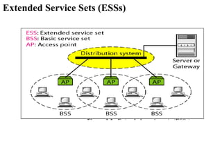
- 93. Extended Service Set • An extended service set (ESS) is made up of two or more BSSs with APs. In this case, the BSSs are connected through a distribution system, which is usually a wired LAN. • The distribution system connects the APs in the BSSs. IEEE 802.11 does not restrict the distribution system; it can be any IEEE LAN such as an Ethernet. • Extended service set uses two types of stations: mobile and stationary. • The mobile stations are normal stations inside a BSS. • The stationary stations are AP stations that are part of a wired LAN. Figure shows an ESS.
- 94. Extended Service Sets (ESSs)
- 95. • When BSSs are connected, the stations within reach of one another can communicate without the use of an AP. However, communication between two stations in two different BSSs usually occurs via two APs. • The idea is similar to communication in a cellular network if we consider each BSS to be a cell and each AP to be a base station. • A mobile station can belong to more than one BSS at the same time.
- 96. STATION TYPES • IEEE 802.11 defines three types of stations based on their mobility in a wireless LAN: no- transition, BSS-transition, and ESS-transition mobility. • A station with no-transition mobility is either stationary (not moving) or moving only inside a BSS. • A station with BSS-transition mobility can move from one BSS to another, but the movement is confined inside one ESS. • A station with ESS-transition mobility can move from one ESS to another.
- 97. MAC SUBLAYER • IEEE 802.11 defines two MAC sublayers: the distributed coordination function (DCF) and point coordination function (PCF). Figure shows the relationship between the two MAC sublayers, the LLC sublayer, and the physical layer.
- 98. Distributed Coordination Function • One of the two protocols defined by IEEE at the MAC sublayer is called the distributed coordination function (DCF). • DCF uses CSMA/CA [Carrier Sense Multiple Access/ Collision Avoidance]as the access method. • Wireless LANs cannot implement CSMA/CD [Carrier Sense Multiple Access/ Collision Detection] for three reasons:
- 99. Distributed Coordination Function three reasons: •For collision detection a station must be able to send data and receive collision signals at the same time. •Collision may not be detected because of the hidden station problem. •The distance between stations can be great. Signal fading could prevent a station at one end from hearing a collision at the other end.
- 100. Distributed Coordination Function Figure : NAV ( Network Allocation Vector) is virtual carrier sensing mechanism used with wireless network protocol such as IEEE 802.11.
- 101. Distributed Coordination Function • Before sending a frame, the source station senses the medium by checking the energy level at the carrier frequency. – The channel uses a persistence strategy with back-off until the channel is idle. – After the station is found to be idle, the station waits for a period of time called the distributed inter-frame space (DIFS); then the station sends a control frame called the request to send (RTS).
- 102. Distributed Coordination Function • After receiving the RTS and waiting a period of time called the short inter-frame space (SIFS), the destination station sends a control frame, called the clear to send (CTS), to the source station. This control frame indicates that the destination station is ready to receive data. • The source station sends data after waiting an amount of time equal to SIFS.
- 103. Distributed Coordination Function • The destination station, after waiting an amount of time equal to SIFS, sends an acknowledgment to show that the frame has been received. • Acknowledgment is needed in this protocol because the station does not have any means to check for the successful arrival of its data at the destination. • On the other hand, the lack of collision in CSMA/CD is a kind of indication to the source that data have arrived.
- 104. Point Coordination Function (PCF) • The point coordination function (PCF) is an optional access method that can be implemented in an infrastructure network (not in an ad-hoc network). • It is implemented on top of the DCF and is used mostly for time-sensitive transmission. • PCF has a centralized, contention-free polling access method. The AP performs polling for stations that are capable of being polled. • The stations are polled one after another, sending any data they have to the AP.
- 105. Point Coordination Function (PCF) • To give priority to PCF over DCF, another set of inter frame spaces has been defined: PIFS and SIFS. • The SIFS is the same as that in DCF, but the PIFS (PCF IFS) is shorter than the DIFS. • This means that if, at the same time, a station wants to use only DCF and an AP wants to use PCF, the AP has priority.
- 106. • Due to the priority of PCF over DCF, stations that only use DCF may not gain access to the medium. To prevent this, a repetition interval has been designed to cover both contention-free (PCF) and contention-based (DCF) traffic. • The repetition interval, which is repeated continuously, starts with a special control frame, called a beacon frame. • When the stations hear the beacon frame, they start their NAV for the duration of the contention-free period of the repetition interval. • NAV ( Network Allocation Vector) is virtual carrier sensing mechanism used with wireless network protocol such as IEEE 802.11.
- 107. • During the repetition interval, the PC (point controller) can send a poll frame, receive data, send an ACK, receive an ACK, or do any combination of these (802.11 uses piggybacking). • At the end of the contention-free period, the PC sends a CF end (contention-free end) frame to allow the contention-based stations to use the medium. • The wireless environment is very noisy; a corrupt frame has to be retransmitted. The protocol, therefore, recommends fragmentation-the division of a large frame into smaller ones. It is more efficient to resend a small frame than a large one.
- 110. WLAN PROBLEMS HIDDEN STATION PROBLEMS • Figure shows an example of the hidden station problem. Station B has a transmission range shown by the left oval (sphere in space); every station in this range can hear any signal transmitted by station B. • Station C has a transmission range shown by the right oval (sphere in space); every station located in this range can hear any signal transmitted by C. • Station C is outside the transmission range of B; likewise, station B is outside the transmission range of C. Station A, however, is in the area covered by both Band C; it can hear any signal transmitted by B or C.
- 112. • Assume that station B is sending data to station A. In the middle of this transmission, station C also has data to send to station A. However, station C is out of B's range and transmissions from B cannot reach C. Therefore C thinks the medium is free. Station C sends its data to A, which results in a collision at A because this station is receiving data from both B and C. • In this case, we say that stations B and C are hidden from each other with respect to A. Hidden stations can reduce the capacity of the network because of the possibility of collision. The solution to the hidden station problem is the use of the handshake frames (RTS and CTS) • The CTS frame in CSMA/CA handshake can prevent collision from a hidden station.
- 114. EXPOSED STATION PROBLEM • Consider a situation that is the inverse of the previous one: the exposed station problem. In this problem a station refrains from using a channel when it is, in fact, available. In Next Figure, station A is transmitting to station B. • Station C has some data to send to station D, which can be sent without interfering with the transmission from A to B. However, station C is exposed to transmission from A; it hears what A is sending and thus refrains from sending. In other words, C is too conservative and wastes the capacity of the channel.
- 116. • Station C hears the RTS from A, but does not hear the CTS from B. Station C, after hearing the RTS from A, can wait for a time so that the CTS from B reaches A; it then sends an RTS to D to show that it needs to communicate with D. Both stations B and A may hear this RTS, but station A is in the sending state, not the receiving state. Station B, however, responds with a CTS. • The problem is here. If station A has started sending its data, station C cannot hear the CTS from station D because of the collision; it cannot send its data to D. It remains exposed until A finishes sending its data as in next Figure.
- 118. BLUETOOTH • A Bluetooth LAN is an ad hoc network, which means that the network is formed spontaneously; the devices, sometimes called gadgets, find each other and make a network called a piconet • Bluetooth technology has several applications. Peripheral devices such as a wireless mouse or keyboard can communicate with the computer through this technology.
- 119. • Monitoring devices can communicate with sensor devices in a small health care center. • Bluetooth technology is the implementation of a protocol defined by the IEEE 802.15 standard. • The standard defines a wireless personal-area network (PAN) operable in an area the size of a room or a hall.
- 120. ARCHITECTURE • Bluetooth defines two types of networks: piconet and scatternet. • Piconets: A Bluetooth network is called a piconet, or a small net. A piconet can have up to eight stations, one of which is called the primary; the rest are called secondaries. • All the secondary stations synchronize their clocks and hopping sequence with the primary. Note that a piconet can have only one primary station. • The communication between the primary and the secondary can be one-to-one or one-to-many. Figure shows a piconet.
- 121. • Although a piconet can have a maximum of seven secondaries, an additional eight secondaries can be in the parked state. A secondary in a parked state is synchronized with the primary, but cannot take part in communication until it is moved from the parked state. • Because only eight stations can be active in a piconet, activating a station from the parked state means that an active station must go to the parked state.
- 122. • Scatternet: Piconets can be combined to form what is called a scatternet. A secondary station in one piconet can be the primary in another piconet. • This station can receive messages from the primary in the first piconet (as a secondary) and, acting as a primary, deliver them to secondaries in the second piconet. A station can be a member of two piconets. Figure illustrates a scatternet.
- 123. Bluetooth Devices A Bluetooth device has a built-in short-range radio transmitter. The current data rate is 1 Mbps with a 2.4- GHz bandwidth.
- 124. Bluetooth Layers • Bluetooth uses several layers that do not exactly match those of the Internet model.
- 125. • Radio Layer: The radio layer is roughly equivalent to the physical layer of the Internet model. Bluetooth devices are low-power and have a range of 10 m. – Band: Bluetooth uses a 2.4-GHz ISM (Industrial Scientific and Medical) band divided into 79 channels of 1 MHz each. – FHSS: Bluetooth uses the frequency-hopping spread spectrum (FHSS) method in the physical layer to avoid interference from other devices or other networks. – Bluetooth hops 1600 times per second, which means that each device changes its modulation frequency 1600 times per second.
- 126. BASEBAND LAYER: •The baseband layer is roughly equivalent to the MAC sublayer in LANs. The access method is TDMA. •The primary and secondary communicate with each other using time slots. •This means that during the time that one frequency is used, a sender sends a frame to a secondary, or a secondary sends a frame to the primary. •Note that the communication is only between the primary and a secondary; secondaries cannot communicate directly with one another.
- 127. • TDMA: Bluetooth uses a form of TDMA that is called TDD-TDMA (time division duplex TDMA). • TDD-TDMA is a kind of half-duplex communication in which the secondary and receiver send and receive data, but not at the same time (half duplex); however, the communication for each direction uses different hops. • This is similar to walkie-talkies using different carrier frequencies.
- 128. Physical Links • Two types of links can be created between a primary and a secondary: SCO links and ACL links. • SCO: A synchronous connection-oriented (SCO) link is used when avoiding latency (delay in data delivery) is more important than integrity (error- free delivery). • In an SCO link, a physical link is created between the primary and a secondary by reserving specific slots at regular intervals.
- 129. Physical Links • The basic unit of connection is two slots, one for each direction. • If a packet is damaged, it is never retransmitted. SCO is used for real-time audio where avoiding delay is all-important. • A secondary can create up to three SCO links with the primary, sending digitized audio (PCM) at 64 kbps in each link. • ACL :An asynchronous connectionless link (ACL) is used when data integrity is more important than avoiding latency.
- 130. • In this type of link, if a payload encapsulated in the frame is corrupted, it is retransmitted. • A secondary returns an ACL frame in the available odd-numbered slot if and only if the previous slot has been addressed to it. • ACL can use one, three, or more slots and can achieve a maximum data rate of 721 kbps.
- 131. L2CAP • The Logical Link Control and Adaptation Protocol, or L2CAP (L2 here means LL), is roughly equivalent to the LLC sublayer in LANs. • It is used for data exchange on an ACL link (If frame is corrupted, it is retransmitted. ); SCQ channels do not use L2CAP. • The 16-bit length field defines the size of the data, in bytes, coming from the upper layers.
- 132. • The L2CAP has specific duties: – Multiplexing, – segmentation and reassembly, – quality of service (QoS), – group management. Multiplexing: – The L2CAP can do multiplexing. At the sender site, it accepts data from one of the upper-layer protocols, frames them, and delivers them to the baseband layer. – At the receiver site, it accepts a frame from the baseband layer, extracts the data, and delivers them to the appropriate protocol layer. L2CAP
- 133. Segmentation and Reassembly: – The L2CAP divides these large packets into segments and adds extra information to define the location of the segments in the original packet. – The L2CAP segments the packet at the source and reassembles them at the destination. L2CAP
- 134. QoS: – Bluetooth allows the stations to define a quality- of-service level. Group Management: – This is similar to multicasting. For example, two or three secondary devices can be part of a multicast group to receive data from the primary. L2CAP