SlideShare a Scribd company logo
Common Network Architecture
Chapter No. 2
Connection oriented Vs Connection less network
Connection-Oriented means that when devices
communicate, they perform handshaking to set up
an end-to-end connection.
In connectionless design every packet is addressed
and routed independently.
Connection oriented Protocols
Characteristics:
1. Handshaking (Setting up connection) between
communicating devices. Connections sometimes
are called as sessions, virtual circuits or logical
connections.
2. Acknowledgement procedure. This provides a
high level of network reliability.
3. It provides means of error control. Whenever
receiving station found that received data packet
consist of errors it request sender to retransmit that
packet.
4. It is a uni-cast (point-to-point) operation.
•Connection-oriented
• Setup data transfer ahead of time (through
handshaking)
• Internet’s connection-oriented service is TCP
(Transmission Control Protocol). It provides :
• reliable, in-order byte delivery
• flow control
• congestion control.
• Applications using TCP: Email (SMTP), web browsing
(HTTP), and file transfer (FTP)
Connectionless (Stateless) Protocols
Characteristics:
• It sends data with a source and destination
address without a handshake.
• Do not use any acknowledgment procedure.
• Usually do not support error control.
• Connectionless protocols are more efficient
than that of connection oriented protocols.
• It allows multicast and broadcast operations.
•Connectionless
Internet’s connectionless service is UDP (User
Datagram Protocol) . It provides
unreliable data transfer
no flow control
no congestion control
Applications using UDP: streaming media, video
conferencing, and IP telephony
A comparison of Connection-Oriented and Connectionless Network
Peer-to-Peer Network
• A peer-to-peer network is a distributed network
architecture composed of participants that make a
portion of their resources, such as processing power,
disk storage or network bandwidth directly to network
participants without the need for central coordination
instances.
• Used largely for sharing of content files such as audio,
video, data or anything in a digital format.
• Can be very large
• End-systems (or peers), are capable of behaving
as clients and servers of data, hence system is
scalable and reliable
• Peers participation is voluntary, membership is
dynamic, hence topology keeps changing
• Most popularly used for file sharing, hence peer-
to-peer systems have become synonymous with
peer-to-peer file sharing networks
Peer-to-Peer Network
A Peer
• Peers are both suppliers and consumers
while in the traditional client-server model,
the server supplies while the client only
consumes.
Peer-To-Peer VS Client-Server
Advantages
• The more nodes that are part of the system,
demand increases and total capacity of the
system also increases. Where in client-server
network architectures as more clients are
added to the system, the system resources
decreases.
• There is no single point of failure, due to
robustness of the system.
• All clients provide to the system
Disadvantages
• Security is a major concern, not all shared files
are from beginning sources. Attackers may add
malware to p2p files as an attempt to take
control of other nodes in the network.
• Heavy bandwidth usage
• ISP speeding/slowing of P2P traffic.
• Potential legal/moral concerns
CO Vs. CL
• In connection oriented service authentication is
needed while connectionless service does not need
any authentication.
• Connection oriented protocol makes a connection
and checks whether message is received or not and
sends again if an error occurs connectionless service
protocol does not guarantees a delivery.
• Connection oriented service is more reliable than
connectionless service.
• Connection oriented service interface is stream
based and connectionless is message based.
Service Primitives
• A service is specified by a set of primitives. A
primitive means operation. To access the
service a user process can access these
primitives.
• These primitives are different for connection
oriented service and connectionless service.
• LISTEN : When a server is ready to accept an incoming
connection it executes the LISTEN primitive. It blocks waiting
for an incoming connection.
• CONNECT : It connects the server by establishing a
connection. Response is awaited.
• RECIEVE: Then the RECIEVE call blocks the server.
• SEND : Then the client executes SEND primitive to transmit its
request followed by the execution of RECIEVE to get the reply.
Send the message.
• DISCONNECT : This primitive is used for terminating the
connection. After this primitive one can’t send any message.
When the client sends DISCONNECT packet then the server
also sends the DISCONNECT packet to acknowledge the client.
When the server package is received by client then the process is
terminated.
Connection Oriented Service Primitives
Primitives for Connectionless Oriented Service
• UNIDATA - This primitive sends a packet of data
• FACILITY, REPORT - Primitive for enquiring
about the performance of the network, like
delivery statistics.
X.25 Networks
• X.25 is a standard used by many older public
networks specially outside the U.S.
• This was developed by CCITT for providing an
interface between public packet-switched
network and their customers.
• The packet switching networks use X.25 protocol
. The X.25 recommendations were first prepared
in 1976 and then revised in 1978, 1980 and 1984.
• X.25 was developed for computer connections,
used for terminal/timesharing connection.
X.25 Networks
• This protocol is based on the protocols used in
early packet switching networks such as
ARPANET, DATAPAC, and TRANSPAC etc.
• A protocol X.21 which is a physical layer
protocol is used to specify the physical electrical
and procedural interface between the host and
network.
• The problem with this standard is that it needs
digital signal rather than analog signals on
telephone lines.
• So not many networks support this standard.
Instead RS 232 standard is defined.
• The data link layer standard has a number of
variations. It is designed for error detection and
corrections.
• The network layer protocol performs the
addressing, flow control, delivery confirmation etc.
• It allows the user to establish virtual circuits and
send packets on them. These packets are delivered
to the destination reliably and in order.
• X.25 is a connection oriented service. It supports
switched virtual circuits as well as the permanent
circuits.
• Packet Switching is a technique whereby the
network routes individual packets of HDLC data
between different destinations based on addressing
within each packet.
• A switched virtual circuit is established between a
computer and network when the computer sends a
packet to the network requesting to make a call to
other computer.
• Packets can then be sent over this connection from
sender to receiver.
• X.25 provides the flow control, to avoid a fast
sender overriding a slow or busy receiver.
• A permanent virtual circuit is analogous to-a leased
line. It is set up in advance with a mutual agreement
between the users.
• Since it is always present, no call set up is required
for its use.
• In order to allow the computers which do not use the
X.25 to communicate with the X.25 network a packet
assembler dis-assembler (PAD) is used.
• PAD is required to be installed along with each
computer which does not use X.25.
• X.25 defines the interface for exchange of packets
between a DTE and switch data sub-network node.
• X.25 Most widely used today
• X.25 is an interface between DTE ( Data Terminal
Equipment) and DCE (Data Communication
Equipment) for terminal operation at the packet mode
on public data network.
– A packet switching protocol used in a wide area
network
– use virtual circuit and asynchronous TDM
• DTE stands for Data Terminal Equipment,
and DCE stands for Data Communications
Equipment.
• DTE is typically either a dumb terminal or the
serial port on a computer/workstation.
• DCE is typically a modem, or other piece of data
communications equipment, hence the names.
Three Layers of X.25
The X.25 interface is defined at three levels:
The three levels are:
(i) Physical layer (level 1)
(ii) Data link layer (level 2)
(iii) Packet layer (level 3).
• Layers
Encapsulation of PLP packet
• These three layers correspond to the three lower
most layers of the ISO-OSI reference model. The
physical layer takes care of the interface between
a computer terminal and the link which attaches it
to the packet switching node.
• The X.25 defines the interface for exchange of
packets between the user's machine (DTE- Data
Terminal Equipment) and the packet switching
node to which this DTE is attached which is
called as DCE(Data Circuit Terminating
Equipment).
• The three layers of X.25 interface are as
shown in Fig..
• At the physical level X.21 physical interface is
being used which is defined for circuit
switched data network. At the data link level,
X.25 specifies the link access procedure-B
(LAP-B) protocol.
Common Network Architecture: X.25 Networks, Ethernet (Standard and Fast): frame format and specifications, Wireless LAN’s – 802.11x, 802.3 Bluetooth etc.
• At the network level (3rd
level), X.25 defines a
protocol for an access to packet data subnetwork.
• This protocol defines the format, content and
procedures for exchange of control and data
transfer packets. The packet layer provides an
external virtual circuit service.
• Next Fig. shows the relationship between the
levels of x.25. User data is passed down to X.25
level 3.
• This data then appends the control information as
a header to form a packet. This control information
is then used in the operation of the protocol.
Common Network Architecture: X.25 Networks, Ethernet (Standard and Fast): frame format and specifications, Wireless LAN’s – 802.11x, 802.3 Bluetooth etc.
• The entire X.25 packet formed at the packet level
is then passed down to the second layer i.e. the
data link layer.
• The control information is appended at the front
and back of the packet forming a LAP-B frame.
The control information in LAP-B frame is
needed for the operation of the LAP-B protocol.
• This frame is then passed to the physical layer
for transmission.
Packet Layer Protocol
• PLP packets : Information packets and Control packets
• Information Packets (I-packets)
– transmit user data
– consists of a header and a user data field
– short and long packets: long packets to support
facilities with long delays
– The last bit in the header = 0 for I-packets
Packet Layer Protocol
• I-packet fields
– General format identifier (GFI) field: 4 bits
• Q bit : not defined in the standard. Users define
two types of data.
• D bit: for packet sequencing.
• Mod: the length of the header. (01: the header
short, 10: long)
– Virtual circuit identification fields
• Logical channel group number (LCGN) : 4 bits
• Logical channel number (LCN) : 8 bits
• total 12 bits to identify the virtual circuit for a
transmission
Packet Layer Protocol
• I-packet fields
• P(S) and P(R) : packet sequence numbers for
flow and error control
• P(S) for packet send, P(R) for packet receive:
sliding window ARQ
Packet Layer Protocol
• Control Packets (C-packets)
~ flow and error control
~ connection, termination and management control
– Category I (for flow and error control)
• RR: Receive Ready - the station is ready to
receive more packets
• RNR: Receive Not Ready
• REJ: Reject - an error in the packet (go-back-n
ARQ)
Packet Layer Protocol
• Control Packet (C-packet)
– Category II
• for connection, termination and management control
• control packet types
Control Packets
• Category II
– Call Request/Incoming Call
• request the establishment of a connection between
two DTEs
– Call Accepted/Call Connected
• indicate the acceptance of the requested connection
by the called system
Control Packets
• Category II (cont’d)
– Clear Request/Clear Indication
• to disconnect the connection at the end of an exchange
– Clear Confirm
• sent in response to the clear indication
– and More...
Packet Layer Protocol
• Complete Packet Sequence
– A message size may be too small or too large for
a network and not compatible with a network.
– X.25 mechanism to break up a long message
among multiple packets but still keep those
packets as a single contiguous transmission
– A packets: at least one additional packets needed
to carry the remainder of a message (M=1,D=0)
- B packets: either stand alone or final packet
(M=0, D=1)
– final packet in the sequence need
ACK( M=1,D=1)
Packet Layer Protocol
• Complete Packet Sequence (cont’d)
Packet Layer Protocol
• Virtual Channel ID Numbers
– up to 4096 multiplexed channels to be identified
between each DTE and DCE
– not permanent, allocated dynamically
– the calling and called hosts use different numbers
Virtual Circuit Service
• With the X.25 packet layer, data are
transmitted in packets over external virtual
circuits, The virtual circuit service of X.25
provides for two types of virtual circuits.
• The virtual circuit service of X.25 provides for
two types of virtual circuits i.e. "virtual call"
and "permanent virtual circuit".
Virtual Circuit Service
• A virtual call is a dynamically established
virtual circuit using a call set up and call
clearing procedure.
• A permanent virtual circuit is a fixed, network
assigned virtual circuit. Data transfer takes
place as with virtual calls, but no call set up or
clearing is required.
Characteristics of X.25
• Multiple logical channels can be set on a single
physical line
• Terminals of different communication speeds can
communicate
• The procedure for transmission controls can be
changed.
Ad

More Related Content

Similar to Common Network Architecture: X.25 Networks, Ethernet (Standard and Fast): frame format and specifications, Wireless LAN’s – 802.11x, 802.3 Bluetooth etc. (20)

CISSP - Chapter 4 - Network Fundamental
CISSP - Chapter 4 - Network FundamentalCISSP - Chapter 4 - Network Fundamental
CISSP - Chapter 4 - Network Fundamental
Karthikeyan Dhayalan
 
Wide Area Network
Wide Area NetworkWide Area Network
Wide Area Network
zaisahil
 
06-Networks-Software.pdf
06-Networks-Software.pdf06-Networks-Software.pdf
06-Networks-Software.pdf
Ministry of Higher Education and Scientific Research
 
Transport Layer In Computer Network
Transport Layer In Computer NetworkTransport Layer In Computer Network
Transport Layer In Computer Network
Destro Destro
 
Presentation of computer network on data link layer
Presentation of computer network on data link layerPresentation of computer network on data link layer
Presentation of computer network on data link layer
sumit gyawali
 
Ccna4 mod5-frame relay
Ccna4 mod5-frame relayCcna4 mod5-frame relay
Ccna4 mod5-frame relay
CYBERINTELLIGENTS
 
Network protocol structure scope
Network protocol structure scopeNetwork protocol structure scope
Network protocol structure scope
Sanat Maharjan
 
Networkprotocolstructurescope 130719081246-phpapp01
Networkprotocolstructurescope 130719081246-phpapp01Networkprotocolstructurescope 130719081246-phpapp01
Networkprotocolstructurescope 130719081246-phpapp01
Gaurav Goyal
 
unit1 network model osi and tcpip.pptx
unit1  network model osi and tcpip.pptxunit1  network model osi and tcpip.pptx
unit1 network model osi and tcpip.pptx
183JAIDEEP
 
CISSP - Chapter 4 - Intranet and extranets
CISSP - Chapter 4 - Intranet and extranetsCISSP - Chapter 4 - Intranet and extranets
CISSP - Chapter 4 - Intranet and extranets
Karthikeyan Dhayalan
 
Frame relay
Frame relay Frame relay
Frame relay
balub4
 
unit 3 computer networks-switching,packet switching,internet protocol.
unit 3 computer networks-switching,packet switching,internet protocol.unit 3 computer networks-switching,packet switching,internet protocol.
unit 3 computer networks-switching,packet switching,internet protocol.
venigkrish89
 
Client Server Network and Peer to Peer.pptx
Client Server Network and Peer to Peer.pptxClient Server Network and Peer to Peer.pptx
Client Server Network and Peer to Peer.pptx
DevChaudhari17
 
internet network for o level
 internet network for o level  internet network for o level
internet network for o level
Samit Singh
 
RODMAN Best way to test continuity between OSI.pptx
RODMAN Best way to test continuity between OSI.pptxRODMAN Best way to test continuity between OSI.pptx
RODMAN Best way to test continuity between OSI.pptx
bilisashobe430
 
Networking
Networking Networking
Networking
FLYMAN TECHNOLOGY LIMITED
 
Chapter 2 computer network PPT CN-1.pptx
Chapter 2 computer network PPT CN-1.pptxChapter 2 computer network PPT CN-1.pptx
Chapter 2 computer network PPT CN-1.pptx
ManasaPM3
 
The OSI model
 The OSI model The OSI model
The OSI model
ShofiqulIslam38
 
Chapter 1 Introduction to Routing and Switching.pptx
Chapter 1 Introduction to Routing and Switching.pptxChapter 1 Introduction to Routing and Switching.pptx
Chapter 1 Introduction to Routing and Switching.pptx
Buntha2
 
network fundamentals
network fundamentalsnetwork fundamentals
network fundamentals
Sithu PM
 
CISSP - Chapter 4 - Network Fundamental
CISSP - Chapter 4 - Network FundamentalCISSP - Chapter 4 - Network Fundamental
CISSP - Chapter 4 - Network Fundamental
Karthikeyan Dhayalan
 
Wide Area Network
Wide Area NetworkWide Area Network
Wide Area Network
zaisahil
 
Transport Layer In Computer Network
Transport Layer In Computer NetworkTransport Layer In Computer Network
Transport Layer In Computer Network
Destro Destro
 
Presentation of computer network on data link layer
Presentation of computer network on data link layerPresentation of computer network on data link layer
Presentation of computer network on data link layer
sumit gyawali
 
Network protocol structure scope
Network protocol structure scopeNetwork protocol structure scope
Network protocol structure scope
Sanat Maharjan
 
Networkprotocolstructurescope 130719081246-phpapp01
Networkprotocolstructurescope 130719081246-phpapp01Networkprotocolstructurescope 130719081246-phpapp01
Networkprotocolstructurescope 130719081246-phpapp01
Gaurav Goyal
 
unit1 network model osi and tcpip.pptx
unit1  network model osi and tcpip.pptxunit1  network model osi and tcpip.pptx
unit1 network model osi and tcpip.pptx
183JAIDEEP
 
CISSP - Chapter 4 - Intranet and extranets
CISSP - Chapter 4 - Intranet and extranetsCISSP - Chapter 4 - Intranet and extranets
CISSP - Chapter 4 - Intranet and extranets
Karthikeyan Dhayalan
 
Frame relay
Frame relay Frame relay
Frame relay
balub4
 
unit 3 computer networks-switching,packet switching,internet protocol.
unit 3 computer networks-switching,packet switching,internet protocol.unit 3 computer networks-switching,packet switching,internet protocol.
unit 3 computer networks-switching,packet switching,internet protocol.
venigkrish89
 
Client Server Network and Peer to Peer.pptx
Client Server Network and Peer to Peer.pptxClient Server Network and Peer to Peer.pptx
Client Server Network and Peer to Peer.pptx
DevChaudhari17
 
internet network for o level
 internet network for o level  internet network for o level
internet network for o level
Samit Singh
 
RODMAN Best way to test continuity between OSI.pptx
RODMAN Best way to test continuity between OSI.pptxRODMAN Best way to test continuity between OSI.pptx
RODMAN Best way to test continuity between OSI.pptx
bilisashobe430
 
Chapter 2 computer network PPT CN-1.pptx
Chapter 2 computer network PPT CN-1.pptxChapter 2 computer network PPT CN-1.pptx
Chapter 2 computer network PPT CN-1.pptx
ManasaPM3
 
Chapter 1 Introduction to Routing and Switching.pptx
Chapter 1 Introduction to Routing and Switching.pptxChapter 1 Introduction to Routing and Switching.pptx
Chapter 1 Introduction to Routing and Switching.pptx
Buntha2
 
network fundamentals
network fundamentalsnetwork fundamentals
network fundamentals
Sithu PM
 

Recently uploaded (20)

Raish Khanji GTU 8th sem Internship Report.pdf
Raish Khanji GTU 8th sem Internship Report.pdfRaish Khanji GTU 8th sem Internship Report.pdf
Raish Khanji GTU 8th sem Internship Report.pdf
RaishKhanji
 
Main cotrol jdbjbdcnxbjbjzjjjcjicbjxbcjcxbjcxb
Main cotrol jdbjbdcnxbjbjzjjjcjicbjxbcjcxbjcxbMain cotrol jdbjbdcnxbjbjzjjjcjicbjxbcjcxbjcxb
Main cotrol jdbjbdcnxbjbjzjjjcjicbjxbcjcxbjcxb
SunilSingh610661
 
Machine learning project on employee attrition detection using (2).pptx
Machine learning project on employee attrition detection using (2).pptxMachine learning project on employee attrition detection using (2).pptx
Machine learning project on employee attrition detection using (2).pptx
rajeswari89780
 
Compiler Design Unit1 PPT Phases of Compiler.pptx
Compiler Design Unit1 PPT Phases of Compiler.pptxCompiler Design Unit1 PPT Phases of Compiler.pptx
Compiler Design Unit1 PPT Phases of Compiler.pptx
RushaliDeshmukh2
 
Smart Storage Solutions.pptx for production engineering
Smart Storage Solutions.pptx for production engineeringSmart Storage Solutions.pptx for production engineering
Smart Storage Solutions.pptx for production engineering
rushikeshnavghare94
 
"Feed Water Heaters in Thermal Power Plants: Types, Working, and Efficiency G...
"Feed Water Heaters in Thermal Power Plants: Types, Working, and Efficiency G..."Feed Water Heaters in Thermal Power Plants: Types, Working, and Efficiency G...
"Feed Water Heaters in Thermal Power Plants: Types, Working, and Efficiency G...
Infopitaara
 
lecture5.pptxJHKGJFHDGTFGYIUOIUIPIOIPUOHIYGUYFGIH
lecture5.pptxJHKGJFHDGTFGYIUOIUIPIOIPUOHIYGUYFGIHlecture5.pptxJHKGJFHDGTFGYIUOIUIPIOIPUOHIYGUYFGIH
lecture5.pptxJHKGJFHDGTFGYIUOIUIPIOIPUOHIYGUYFGIH
Abodahab
 
Compiler Design_Lexical Analysis phase.pptx
Compiler Design_Lexical Analysis phase.pptxCompiler Design_Lexical Analysis phase.pptx
Compiler Design_Lexical Analysis phase.pptx
RushaliDeshmukh2
 
ADVXAI IN MALWARE ANALYSIS FRAMEWORK: BALANCING EXPLAINABILITY WITH SECURITY
ADVXAI IN MALWARE ANALYSIS FRAMEWORK: BALANCING EXPLAINABILITY WITH SECURITYADVXAI IN MALWARE ANALYSIS FRAMEWORK: BALANCING EXPLAINABILITY WITH SECURITY
ADVXAI IN MALWARE ANALYSIS FRAMEWORK: BALANCING EXPLAINABILITY WITH SECURITY
ijscai
 
Introduction to FLUID MECHANICS & KINEMATICS
Introduction to FLUID MECHANICS &  KINEMATICSIntroduction to FLUID MECHANICS &  KINEMATICS
Introduction to FLUID MECHANICS & KINEMATICS
narayanaswamygdas
 
Mathematical foundation machine learning.pdf
Mathematical foundation machine learning.pdfMathematical foundation machine learning.pdf
Mathematical foundation machine learning.pdf
TalhaShahid49
 
Lidar for Autonomous Driving, LiDAR Mapping for Driverless Cars.pptx
Lidar for Autonomous Driving, LiDAR Mapping for Driverless Cars.pptxLidar for Autonomous Driving, LiDAR Mapping for Driverless Cars.pptx
Lidar for Autonomous Driving, LiDAR Mapping for Driverless Cars.pptx
RishavKumar530754
 
15th International Conference on Computer Science, Engineering and Applicatio...
15th International Conference on Computer Science, Engineering and Applicatio...15th International Conference on Computer Science, Engineering and Applicatio...
15th International Conference on Computer Science, Engineering and Applicatio...
IJCSES Journal
 
Oil-gas_Unconventional oil and gass_reseviours.pdf
Oil-gas_Unconventional oil and gass_reseviours.pdfOil-gas_Unconventional oil and gass_reseviours.pdf
Oil-gas_Unconventional oil and gass_reseviours.pdf
M7md3li2
 
Process Parameter Optimization for Minimizing Springback in Cold Drawing Proc...
Process Parameter Optimization for Minimizing Springback in Cold Drawing Proc...Process Parameter Optimization for Minimizing Springback in Cold Drawing Proc...
Process Parameter Optimization for Minimizing Springback in Cold Drawing Proc...
Journal of Soft Computing in Civil Engineering
 
LECTURE-16 EARTHEN DAM - II.pptx it's uses
LECTURE-16 EARTHEN DAM - II.pptx it's usesLECTURE-16 EARTHEN DAM - II.pptx it's uses
LECTURE-16 EARTHEN DAM - II.pptx it's uses
CLokeshBehera123
 
introduction to machine learining for beginers
introduction to machine learining for beginersintroduction to machine learining for beginers
introduction to machine learining for beginers
JoydebSheet
 
new ppt artificial intelligence historyyy
new ppt artificial intelligence historyyynew ppt artificial intelligence historyyy
new ppt artificial intelligence historyyy
PianoPianist
 
Resistance measurement and cfd test on darpa subboff model
Resistance measurement and cfd test on darpa subboff modelResistance measurement and cfd test on darpa subboff model
Resistance measurement and cfd test on darpa subboff model
INDIAN INSTITUTE OF TECHNOLOGY KHARAGPUR
 
New Microsoft PowerPoint Presentation.pdf
New Microsoft PowerPoint Presentation.pdfNew Microsoft PowerPoint Presentation.pdf
New Microsoft PowerPoint Presentation.pdf
mohamedezzat18803
 
Raish Khanji GTU 8th sem Internship Report.pdf
Raish Khanji GTU 8th sem Internship Report.pdfRaish Khanji GTU 8th sem Internship Report.pdf
Raish Khanji GTU 8th sem Internship Report.pdf
RaishKhanji
 
Main cotrol jdbjbdcnxbjbjzjjjcjicbjxbcjcxbjcxb
Main cotrol jdbjbdcnxbjbjzjjjcjicbjxbcjcxbjcxbMain cotrol jdbjbdcnxbjbjzjjjcjicbjxbcjcxbjcxb
Main cotrol jdbjbdcnxbjbjzjjjcjicbjxbcjcxbjcxb
SunilSingh610661
 
Machine learning project on employee attrition detection using (2).pptx
Machine learning project on employee attrition detection using (2).pptxMachine learning project on employee attrition detection using (2).pptx
Machine learning project on employee attrition detection using (2).pptx
rajeswari89780
 
Compiler Design Unit1 PPT Phases of Compiler.pptx
Compiler Design Unit1 PPT Phases of Compiler.pptxCompiler Design Unit1 PPT Phases of Compiler.pptx
Compiler Design Unit1 PPT Phases of Compiler.pptx
RushaliDeshmukh2
 
Smart Storage Solutions.pptx for production engineering
Smart Storage Solutions.pptx for production engineeringSmart Storage Solutions.pptx for production engineering
Smart Storage Solutions.pptx for production engineering
rushikeshnavghare94
 
"Feed Water Heaters in Thermal Power Plants: Types, Working, and Efficiency G...
"Feed Water Heaters in Thermal Power Plants: Types, Working, and Efficiency G..."Feed Water Heaters in Thermal Power Plants: Types, Working, and Efficiency G...
"Feed Water Heaters in Thermal Power Plants: Types, Working, and Efficiency G...
Infopitaara
 
lecture5.pptxJHKGJFHDGTFGYIUOIUIPIOIPUOHIYGUYFGIH
lecture5.pptxJHKGJFHDGTFGYIUOIUIPIOIPUOHIYGUYFGIHlecture5.pptxJHKGJFHDGTFGYIUOIUIPIOIPUOHIYGUYFGIH
lecture5.pptxJHKGJFHDGTFGYIUOIUIPIOIPUOHIYGUYFGIH
Abodahab
 
Compiler Design_Lexical Analysis phase.pptx
Compiler Design_Lexical Analysis phase.pptxCompiler Design_Lexical Analysis phase.pptx
Compiler Design_Lexical Analysis phase.pptx
RushaliDeshmukh2
 
ADVXAI IN MALWARE ANALYSIS FRAMEWORK: BALANCING EXPLAINABILITY WITH SECURITY
ADVXAI IN MALWARE ANALYSIS FRAMEWORK: BALANCING EXPLAINABILITY WITH SECURITYADVXAI IN MALWARE ANALYSIS FRAMEWORK: BALANCING EXPLAINABILITY WITH SECURITY
ADVXAI IN MALWARE ANALYSIS FRAMEWORK: BALANCING EXPLAINABILITY WITH SECURITY
ijscai
 
Introduction to FLUID MECHANICS & KINEMATICS
Introduction to FLUID MECHANICS &  KINEMATICSIntroduction to FLUID MECHANICS &  KINEMATICS
Introduction to FLUID MECHANICS & KINEMATICS
narayanaswamygdas
 
Mathematical foundation machine learning.pdf
Mathematical foundation machine learning.pdfMathematical foundation machine learning.pdf
Mathematical foundation machine learning.pdf
TalhaShahid49
 
Lidar for Autonomous Driving, LiDAR Mapping for Driverless Cars.pptx
Lidar for Autonomous Driving, LiDAR Mapping for Driverless Cars.pptxLidar for Autonomous Driving, LiDAR Mapping for Driverless Cars.pptx
Lidar for Autonomous Driving, LiDAR Mapping for Driverless Cars.pptx
RishavKumar530754
 
15th International Conference on Computer Science, Engineering and Applicatio...
15th International Conference on Computer Science, Engineering and Applicatio...15th International Conference on Computer Science, Engineering and Applicatio...
15th International Conference on Computer Science, Engineering and Applicatio...
IJCSES Journal
 
Oil-gas_Unconventional oil and gass_reseviours.pdf
Oil-gas_Unconventional oil and gass_reseviours.pdfOil-gas_Unconventional oil and gass_reseviours.pdf
Oil-gas_Unconventional oil and gass_reseviours.pdf
M7md3li2
 
LECTURE-16 EARTHEN DAM - II.pptx it's uses
LECTURE-16 EARTHEN DAM - II.pptx it's usesLECTURE-16 EARTHEN DAM - II.pptx it's uses
LECTURE-16 EARTHEN DAM - II.pptx it's uses
CLokeshBehera123
 
introduction to machine learining for beginers
introduction to machine learining for beginersintroduction to machine learining for beginers
introduction to machine learining for beginers
JoydebSheet
 
new ppt artificial intelligence historyyy
new ppt artificial intelligence historyyynew ppt artificial intelligence historyyy
new ppt artificial intelligence historyyy
PianoPianist
 
New Microsoft PowerPoint Presentation.pdf
New Microsoft PowerPoint Presentation.pdfNew Microsoft PowerPoint Presentation.pdf
New Microsoft PowerPoint Presentation.pdf
mohamedezzat18803
 
Ad

Common Network Architecture: X.25 Networks, Ethernet (Standard and Fast): frame format and specifications, Wireless LAN’s – 802.11x, 802.3 Bluetooth etc.

  • 2. Connection oriented Vs Connection less network Connection-Oriented means that when devices communicate, they perform handshaking to set up an end-to-end connection. In connectionless design every packet is addressed and routed independently.
  • 3. Connection oriented Protocols Characteristics: 1. Handshaking (Setting up connection) between communicating devices. Connections sometimes are called as sessions, virtual circuits or logical connections. 2. Acknowledgement procedure. This provides a high level of network reliability. 3. It provides means of error control. Whenever receiving station found that received data packet consist of errors it request sender to retransmit that packet. 4. It is a uni-cast (point-to-point) operation.
  • 4. •Connection-oriented • Setup data transfer ahead of time (through handshaking) • Internet’s connection-oriented service is TCP (Transmission Control Protocol). It provides : • reliable, in-order byte delivery • flow control • congestion control. • Applications using TCP: Email (SMTP), web browsing (HTTP), and file transfer (FTP)
  • 5. Connectionless (Stateless) Protocols Characteristics: • It sends data with a source and destination address without a handshake. • Do not use any acknowledgment procedure. • Usually do not support error control. • Connectionless protocols are more efficient than that of connection oriented protocols. • It allows multicast and broadcast operations.
  • 6. •Connectionless Internet’s connectionless service is UDP (User Datagram Protocol) . It provides unreliable data transfer no flow control no congestion control Applications using UDP: streaming media, video conferencing, and IP telephony
  • 7. A comparison of Connection-Oriented and Connectionless Network
  • 8. Peer-to-Peer Network • A peer-to-peer network is a distributed network architecture composed of participants that make a portion of their resources, such as processing power, disk storage or network bandwidth directly to network participants without the need for central coordination instances. • Used largely for sharing of content files such as audio, video, data or anything in a digital format. • Can be very large
  • 9. • End-systems (or peers), are capable of behaving as clients and servers of data, hence system is scalable and reliable • Peers participation is voluntary, membership is dynamic, hence topology keeps changing • Most popularly used for file sharing, hence peer- to-peer systems have become synonymous with peer-to-peer file sharing networks Peer-to-Peer Network
  • 10. A Peer • Peers are both suppliers and consumers while in the traditional client-server model, the server supplies while the client only consumes.
  • 12. Advantages • The more nodes that are part of the system, demand increases and total capacity of the system also increases. Where in client-server network architectures as more clients are added to the system, the system resources decreases. • There is no single point of failure, due to robustness of the system. • All clients provide to the system
  • 13. Disadvantages • Security is a major concern, not all shared files are from beginning sources. Attackers may add malware to p2p files as an attempt to take control of other nodes in the network. • Heavy bandwidth usage • ISP speeding/slowing of P2P traffic. • Potential legal/moral concerns
  • 14. CO Vs. CL • In connection oriented service authentication is needed while connectionless service does not need any authentication. • Connection oriented protocol makes a connection and checks whether message is received or not and sends again if an error occurs connectionless service protocol does not guarantees a delivery. • Connection oriented service is more reliable than connectionless service. • Connection oriented service interface is stream based and connectionless is message based.
  • 15. Service Primitives • A service is specified by a set of primitives. A primitive means operation. To access the service a user process can access these primitives. • These primitives are different for connection oriented service and connectionless service.
  • 16. • LISTEN : When a server is ready to accept an incoming connection it executes the LISTEN primitive. It blocks waiting for an incoming connection. • CONNECT : It connects the server by establishing a connection. Response is awaited. • RECIEVE: Then the RECIEVE call blocks the server. • SEND : Then the client executes SEND primitive to transmit its request followed by the execution of RECIEVE to get the reply. Send the message. • DISCONNECT : This primitive is used for terminating the connection. After this primitive one can’t send any message. When the client sends DISCONNECT packet then the server also sends the DISCONNECT packet to acknowledge the client. When the server package is received by client then the process is terminated. Connection Oriented Service Primitives
  • 17. Primitives for Connectionless Oriented Service • UNIDATA - This primitive sends a packet of data • FACILITY, REPORT - Primitive for enquiring about the performance of the network, like delivery statistics.
  • 18. X.25 Networks • X.25 is a standard used by many older public networks specially outside the U.S. • This was developed by CCITT for providing an interface between public packet-switched network and their customers. • The packet switching networks use X.25 protocol . The X.25 recommendations were first prepared in 1976 and then revised in 1978, 1980 and 1984. • X.25 was developed for computer connections, used for terminal/timesharing connection.
  • 19. X.25 Networks • This protocol is based on the protocols used in early packet switching networks such as ARPANET, DATAPAC, and TRANSPAC etc. • A protocol X.21 which is a physical layer protocol is used to specify the physical electrical and procedural interface between the host and network. • The problem with this standard is that it needs digital signal rather than analog signals on telephone lines.
  • 20. • So not many networks support this standard. Instead RS 232 standard is defined. • The data link layer standard has a number of variations. It is designed for error detection and corrections. • The network layer protocol performs the addressing, flow control, delivery confirmation etc. • It allows the user to establish virtual circuits and send packets on them. These packets are delivered to the destination reliably and in order. • X.25 is a connection oriented service. It supports switched virtual circuits as well as the permanent circuits.
  • 21. • Packet Switching is a technique whereby the network routes individual packets of HDLC data between different destinations based on addressing within each packet. • A switched virtual circuit is established between a computer and network when the computer sends a packet to the network requesting to make a call to other computer. • Packets can then be sent over this connection from sender to receiver. • X.25 provides the flow control, to avoid a fast sender overriding a slow or busy receiver.
  • 22. • A permanent virtual circuit is analogous to-a leased line. It is set up in advance with a mutual agreement between the users. • Since it is always present, no call set up is required for its use. • In order to allow the computers which do not use the X.25 to communicate with the X.25 network a packet assembler dis-assembler (PAD) is used. • PAD is required to be installed along with each computer which does not use X.25. • X.25 defines the interface for exchange of packets between a DTE and switch data sub-network node.
  • 23. • X.25 Most widely used today • X.25 is an interface between DTE ( Data Terminal Equipment) and DCE (Data Communication Equipment) for terminal operation at the packet mode on public data network. – A packet switching protocol used in a wide area network – use virtual circuit and asynchronous TDM
  • 24. • DTE stands for Data Terminal Equipment, and DCE stands for Data Communications Equipment. • DTE is typically either a dumb terminal or the serial port on a computer/workstation. • DCE is typically a modem, or other piece of data communications equipment, hence the names.
  • 25. Three Layers of X.25 The X.25 interface is defined at three levels: The three levels are: (i) Physical layer (level 1) (ii) Data link layer (level 2) (iii) Packet layer (level 3).
  • 28. • These three layers correspond to the three lower most layers of the ISO-OSI reference model. The physical layer takes care of the interface between a computer terminal and the link which attaches it to the packet switching node. • The X.25 defines the interface for exchange of packets between the user's machine (DTE- Data Terminal Equipment) and the packet switching node to which this DTE is attached which is called as DCE(Data Circuit Terminating Equipment).
  • 29. • The three layers of X.25 interface are as shown in Fig.. • At the physical level X.21 physical interface is being used which is defined for circuit switched data network. At the data link level, X.25 specifies the link access procedure-B (LAP-B) protocol.
  • 31. • At the network level (3rd level), X.25 defines a protocol for an access to packet data subnetwork. • This protocol defines the format, content and procedures for exchange of control and data transfer packets. The packet layer provides an external virtual circuit service. • Next Fig. shows the relationship between the levels of x.25. User data is passed down to X.25 level 3. • This data then appends the control information as a header to form a packet. This control information is then used in the operation of the protocol.
  • 33. • The entire X.25 packet formed at the packet level is then passed down to the second layer i.e. the data link layer. • The control information is appended at the front and back of the packet forming a LAP-B frame. The control information in LAP-B frame is needed for the operation of the LAP-B protocol. • This frame is then passed to the physical layer for transmission.
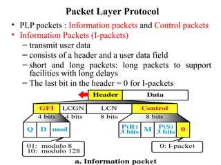
  • 34. Packet Layer Protocol • PLP packets : Information packets and Control packets • Information Packets (I-packets) – transmit user data – consists of a header and a user data field – short and long packets: long packets to support facilities with long delays – The last bit in the header = 0 for I-packets
  • 35. Packet Layer Protocol • I-packet fields – General format identifier (GFI) field: 4 bits • Q bit : not defined in the standard. Users define two types of data. • D bit: for packet sequencing. • Mod: the length of the header. (01: the header short, 10: long) – Virtual circuit identification fields • Logical channel group number (LCGN) : 4 bits • Logical channel number (LCN) : 8 bits • total 12 bits to identify the virtual circuit for a transmission
  • 36. Packet Layer Protocol • I-packet fields • P(S) and P(R) : packet sequence numbers for flow and error control • P(S) for packet send, P(R) for packet receive: sliding window ARQ
  • 37. Packet Layer Protocol • Control Packets (C-packets) ~ flow and error control ~ connection, termination and management control – Category I (for flow and error control) • RR: Receive Ready - the station is ready to receive more packets • RNR: Receive Not Ready • REJ: Reject - an error in the packet (go-back-n ARQ)
  • 38. Packet Layer Protocol • Control Packet (C-packet) – Category II • for connection, termination and management control • control packet types
  • 39. Control Packets • Category II – Call Request/Incoming Call • request the establishment of a connection between two DTEs – Call Accepted/Call Connected • indicate the acceptance of the requested connection by the called system
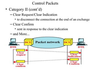
  • 40. Control Packets • Category II (cont’d) – Clear Request/Clear Indication • to disconnect the connection at the end of an exchange – Clear Confirm • sent in response to the clear indication – and More...
  • 41. Packet Layer Protocol • Complete Packet Sequence – A message size may be too small or too large for a network and not compatible with a network. – X.25 mechanism to break up a long message among multiple packets but still keep those packets as a single contiguous transmission – A packets: at least one additional packets needed to carry the remainder of a message (M=1,D=0) - B packets: either stand alone or final packet (M=0, D=1) – final packet in the sequence need ACK( M=1,D=1)
  • 42. Packet Layer Protocol • Complete Packet Sequence (cont’d)
  • 43. Packet Layer Protocol • Virtual Channel ID Numbers – up to 4096 multiplexed channels to be identified between each DTE and DCE – not permanent, allocated dynamically – the calling and called hosts use different numbers
  • 44. Virtual Circuit Service • With the X.25 packet layer, data are transmitted in packets over external virtual circuits, The virtual circuit service of X.25 provides for two types of virtual circuits. • The virtual circuit service of X.25 provides for two types of virtual circuits i.e. "virtual call" and "permanent virtual circuit".
  • 45. Virtual Circuit Service • A virtual call is a dynamically established virtual circuit using a call set up and call clearing procedure. • A permanent virtual circuit is a fixed, network assigned virtual circuit. Data transfer takes place as with virtual calls, but no call set up or clearing is required.
  • 46. Characteristics of X.25 • Multiple logical channels can be set on a single physical line • Terminals of different communication speeds can communicate • The procedure for transmission controls can be changed.