SlideShare a Scribd company logo
Edited & Compiled by: Prof. Krishnananda L, Dept of ECE, Govt SKSJTI Bengaluru Page 1
Introduction
About Network Layer Protocols
 Communication at the network layer is host-to-host (source -to-
destination). The packet sent by the source may pass through several LANs
or WANs before reaching the destination. 
 A global addressing scheme called logical (IP) addressing in required for
this communication.
 Network layer in the Internet has a main protocol (IPv4) and few auxiliary
protocols. IP is responsible for packetizing, forwarding and delivery of a
packet (datagram) to the destination. ICMPv4 helps IP to handle some
errors, IGMP helps in Multicasting, ARP & RARP help in Logical-to-link
layer address translation and viceversa. 
 Communication at the network layer in the Internet is connectionless; so,
unreliable. i.e., IP provides “best-effort” service. Best effort means: packets
may be duplicated, lost, corrupted, delayed, arrive out-of-order,
undelivered or wrongly delivered. IP does not guarantee the delivery of the
packet to the destination and does not have mechanisms for flow control or
error control. This is the job of upper (Transport) layer.
Edited & Compiled by: Prof. Krishnananda L, Dept of ECE, Govt SKSJTI Bengaluru Page 2
 To summarize: IPv4 is a connectionless, unreliable protocol providing “best-
effort” delivery service using “datagram approach” to forward the packets. In
this approach, each datagram is treated independently (even though source and
destination are same) and may travel through different paths to reach the
destination.
If reliability is important, IPv4 must be paired with a reliable, connection-
oriented higher layer protocol like TCP.

Edited & Compiled by: Prof. Krishnananda L, Dept of ECE, Govt SKSJTI Bengaluru Page 3
19.1.1 IPv4 Datagram Format
Edited & Compiled by: Prof. Krishnananda L, Dept of ECE, Govt SKSJTI Bengaluru Page 4
 The Internet Protocol version 4 (IPv4) is the delivery mechanism used by the Internet.
 Packets used by the IP are called datagrams. A datagram is a variable-length packet
consisting of two parts: header and payload (data).
The header is of variable length from 20 to 60 bytes and contains information essential to
routing and delivery. The header is shown as 4-byte sections or rows.
The fields of the IPv4 datagram Header are:
Row 1 (4 bytes = 32 bits):
 Version Number VER (4 bits): This field defines the version of the IPv4 protocol. (present
value is 0100 =4).
 Header Length HLEN (4 bits): This field defines the total length of the datagram header in 4-
byte words. Since HLEN is 4-bit size, Min. value should be 5 and Max. value is 15 (11112).
So, the actual header length in bytes = HLEN value in decimal x 4 (HLEN value multiply by 4)
 Service Type (8 bits): Originally, this field was referred to as type of service (TOS), which
defined how the datagram should be handled. Later, IETF redefined the field to provide
differentiated services (DiffServ) to provide QoS.
 Total Length (16 bits): This 16-bit field defines the total length (header plus payload) of the
IP datagram in bytes. Max datagram length is 65535 bytes.
Payload (data) Length in bytes = total length – header length =total length –{(HLEN) × 4}
Edited & Compiled by: Prof. Krishnananda L, Dept of ECE, Govt SKSJTI Bengaluru Page 5
Row 2 (4 bytes = 32 bits):
 Identification ID (16 bits): This field identifies each datagram originating from the source
host. This field is a counter value initialized to a positive number by the source. When the IP
protocol sends a datagram, it increments the counter by one. When a datagram is
fragmented, the value in the ID field is copied into all fragments, i.e., all fragments of a
datagram have the same ID. The ID helps the destination in reassembling the datagram. The
combination of ID and source IP address together uniquely specifies the datagram
 Flags (3 bits):
 Fragmentation offset (13 bits): These two fields we shall discuss with fragmentation.
Row 3 (4 bytes = 32 bits):
 Time-to-Live (TTL) (8-bits): Used to control the maximum number of hops a datagram can
travel in the network before reaching the destination. Its positive number inserted by the
source. At every router, this value is decremented by 1 and if it reaches 0, datagram is
discarded. Helps to have finite lifetime for a packet instead of looping in the Internet
indefinitely.
 Protocol (8 bits): The network layer carries the payload given by upper layer protocols.
This field indicates which other protocol is using the services of IP. When the datagram
arrives at the destination, the value of this field helps to identify to which protocol the
payload should be delivered.
 Header Checksum (16 bits): IP includes mechanism for Header error detection (not the
payload). Checksum is a method of error detection which is the complement of the sum of
other fields calculated using 1s complement arithmetic.
Edited & Compiled by: Prof. Krishnananda L, Dept of ECE, Govt SKSJTI Bengaluru Page 6

Row 4 (4 bytes = 32 bits):
Source Address (32-bits): This is the 32-bit IPv4 address of the source host Ex: 152.34.56.78
Row 5 (4 bytes = 32 bits):
Destination Address (32-bits): This is the 32-bit IPv4 address of the destination host.
Ex: 75.83.125.140
The above 5 rows (total of 20 bytes) is fixed part of IPv4 Header & is mandatory.
Row 6:
Options + Padding (0 to 40 bytes): This field is NOT mandatory to be a part of the header and is
used for network testing & debugging. Max. length of this field, if present, is 40 bytes.
Edited & Compiled by: Prof. Krishnananda L, Dept of ECE, Govt SKSJTI Bengaluru Page 7
Fragmentation
 A datagram can travel through different networks. For ex, if a router connects a LAN to a
WAN, it receives a frame in the LAN format and sends a frame in the WAN format. The
format and size of the frames vary from one network to another.
 Each link-layer protocol (802.3, 802.11 etc) has its own frame format and size. When a
datagram is encapsulated in a frame, the total size of the datagram must be less than this
maximum size called Maximum Transfer Unit (MTU).
 MTU defined by the restrictions imposed by the hardware and software used in the
network. The value of MTU varies from one network to other. For ex., the MTU in 802.3
LAN is 1500 bytes.
 However, as seen earlier, the maximum size of IP datagram is 65,535 bytes. So, when it
is passed through other networks like LAN, the IP datagram needs to be divided into
smaller size blocks (called fragments). This process is known as Fragmentation. A
datagram may be fragmented several times before it reaches the final destination.
Edited & Compiled by: Prof. Krishnananda L, Dept of ECE, Govt SKSJTI Bengaluru Page 8
 A datagram can be fragmented by the source host or any router in the path. The reassembly
of the datagram is done only by the destination host, after it receives all fragments of a
datagram.
 When a datagram is fragmented, each fragment has its own header. The host or router that
fragments a datagram must change the values of three fields: flags, fragmentation offset, and
total length. The rest of the fields are copied from the original datagram.
We shall now look into fields of IPv4 Header related to fragmentation
Row 2 of the Header:
 Flags (3 bits): This field defines 3 flags. The leftmost bit is reserved (not used). The second
bit (D bit) is called the do not fragment bit. If its value is 1, the machine must not fragment
the datagram. If its value is 0, the datagram can be fragmented if necessary. The third bit (M
bit) is called the more fragment bit. If its value is 1, it means the datagram is not the last
fragment; there are more fragments after this one. If its value is 0, it means this is the last or
only fragment.
 Fragmentation Offset (13 bits): This field shows the relative position of this fragment with
respect to the whole datagram. It is the offset of the data in the original datagram measured
in units of 8 bytes.
 Fig 19.6 shows a datagram with a size of 4000 bytes divided into 3 fragments. The bytes in
the original datagram are numbered 0 to 3999. The first fragment carries bytes 0 to 1399.
The offset for this datagram is 0/8 = 0. The second fragment carries bytes 1400 to 2799; the
Edited & Compiled by: Prof. Krishnananda L, Dept of ECE, Govt SKSJTI Bengaluru Page 9
offset value for this fragment is 1400/8 = 175. Finally, the third fragment carries bytes 2800
to 3999. The offset value for this fragment is 2800/8 = 350.
Note: The length of the offset field is 13 bits and cannot represent a sequence of bytes greater
than 8191. So, choose the size of each fragment so that the first byte number is divisible by 8
 Fig. 19.7 shows detailed Fragmentation of Fig.19.6. The value of the ID field is the same in all
fragments. In the “flag” field, the M bit is set (logic 1) for all fragments except the last. Also,
the value of the offset field for each fragment is shown. Although the fragments arrived out
of order at the destination, they can be correctly reassembled.
 What happens if a fragment itself is fragmented? In this case, the value of the offset field is
always relative to the original datagram. For ex, the second fragment is itself fragmented
into two fragments of 800 bytes and 600 bytes, but the offset shows the relative position of
the fragments to the original data
Edited & Compiled by: Prof. Krishnananda L, Dept of ECE, Govt SKSJTI Bengaluru Page 10
Edited & Compiled by: Prof. Krishnananda L, Dept of ECE, Govt SKSJTI Bengaluru Page 11
Example 1: An IPv4 packet has arrived with the first 8 bits as (01000010)2. The receiver discards
the packet. Why?
Solution:
There is an error in this packet. The 4 leftmost bits (0100)2 show the version, which is
correct. The next 4 bits (0010)2 show an invalid HLEN value (2). The minimum HLEN
value has to be 5, because min. number of bytes in the header must be 20. The packet has
been corrupted in transmission.
Example 2: In an IPv4 packet, the value of HLEN is (1000)2. How many bytes of options are being
carried by this packet?
Solution:
The HLEN value is 8, the total number of bytes in the header is 8 × 4 = 32 bytes. The
first 20 bytes are the base header. So, the next 12 bytes are the options.
Example 3: In an IPv4 packet, the value of HLEN is 5, and the value of the total length field is
(0028)16. How many bytes of data are being carried by this packet?
Solution:
The HLEN value is 5. So the header size is 5 × 4 = 20 bytes (no options). The total length
is (0028)16 or 40 bytes, which means the packet is carrying 20 bytes of data (40 − 20).
Example 4: An IPv4 packet has arrived with the first few hexadecimal digits as shown.
(460000320008000005062…)16. Compute the following:
a) Header length b) Data length c) How many bytes in the options d) ID of the packet?
e) The number of hops packet can travel? f) The data belong to what upper-layer protocol?
Edited & Compiled by: Prof. Krishnananda L, Dept of ECE, Govt SKSJTI Bengaluru Page 12
Solution
Divide the given data into Row1 bits, Row2 bits etc.
Row1 (4 bytes): 46 00 0032 Row2 (4 bytes): 0008 0000 Row3:05 06……
 Row1 gives, protocol version, HLEN, service type and total length.
a) Header length in bytes = HLEN x 4 = 6x4 = 24 bytes
b) Total length is 003216 = 50 bytes.
So, data length = total length – header length = 50-24 = 26 bytes
c) Header length is 24 bytes. Mandatory 20 bytes. So, Options = 24-20 = 4 bytes
 Row2 gives ID, Flags etc
d) ID of the packet is: 8
 Row3 gives TTL, Protocol type etc
e) The TTL field is (05)16. So, packet can travel 5 hops before getting discarded.
f) The protocol field has the value (06)16, so, the upper-layer protocol is TCP.
Example 5: Checksum calculation for an IPv4 header without options.
Solution:
The header is divided into 16-bit sections. All the sections are added and the sum is
complemented after wrapping the leftmost digit. The result is inserted in the checksum field.
The calculation of wrapped sum and checksum can also be done hexadecimal.
Wrapped Sum= Sum Mod FFFF
Checksum=FFFF—Wrapped Sum
Edited & Compiled by: Prof. Krishnananda L, Dept of ECE, Govt SKSJTI Bengaluru Page 13
Edited & Compiled by: Prof. Krishnananda L, Dept of ECE, Govt SKSJTI Bengaluru Page 14
Example 6. A packet has arrived with an M bit value of 0. Is this the first fragment, the last
fragment, or a middle fragment? Do we know if the packet was fragmented?
Solution
If the M bit is 0, it means that there are no more fragments; the fragment is the last one.
However, we cannot say if the original packet was fragmented or not. A nonfragmented
packet is considered the last fragment.
Example 7. A packet has arrived with an M bit value of 1. Is this the first fragment, the last
fragment, or a middle fragment? Do we know if the packet was fragmented?
Solution
If the M bit is 1, it means that there is at least one more fragment. This fragment can be
the first one or a middle one, but not the last one. The packet is definitely fragmented.
Example 8. A packet has arrived with an M bit value of 1 and a fragmentation offset value of 0. Is
this the first fragment, the last fragment, or a middle fragment?
Solution
Because the M bit is 1, it is either the first fragment or a middle one. Because the offset
value is 0, it is the first fragment.
Example 9. A packet has arrived in which the offset value is 100. What is the number of the first
byte? Do we know the number of the last byte?
Solution
To find the number of the first byte, we multiply the offset value by 8. This means that
the first byte number is 800. We cannot determine the number of the last byte unless we
know the length of the data.
Edited & Compiled by: Prof. Krishnananda L, Dept of ECE, Govt SKSJTI Bengaluru Page 15
Example 10. A packet has arrived in which the offset value is 100, the value of HLEN is 5, and
the value of the total length field is 100. What are the numbers of the first byte and the last
byte?
Solution
The first byte number is 100 × 8 = 800. The total length is 100 bytes, and the header
length is 20 bytes (5 × 4), which means that there are 80 bytes in this datagram. If the
first byte number is 800, the last byte number must be 879.
Computer Communication Networks- 17EC64 Module 3 WLANs
Compiled by: Prof. Krishnananda L, Dept of ECE, Govt SKSJTI, Bengaluru Page 16
19.1.4 Security of IPv4 Datagrams
 No security was provided for the IPv4 protocol
when it was originally developed.
 There are three security issues/attacks applicable to the IP
protocol: Packet sniffing, packet modification, and IP
spoofing.
1) Packet Sniffing
An intruder may intercept an IP packet and make a copy of it. Packet
sniffing is a passive attack, in which the attacker does not change the
contents of the packet. This type of attack is very difficult to detect
because the sender and the receiver may never know that the packet
has been copied. One solution is encryption of the packet. The
attacker may still sniff the packet, but the content is cannot be
deciphered.
2) Packet Modification
The second type of attack is to modify the packet. The attacker
intercepts the packet, changes its contents, and sends the new packet
to the receiver. The receiver believes that the packet is coming from
the original sender. This type of attack can be detected using a data
integrity mechanism.
3) IP Spoofing
An attacker can masquerade as somebody else and create an IP
packet that carries the source address of another computer. An
attacker can send an IP packet to a bank pretending that it is coming
from one of the customers. This type of attack can be prevented using
an origin authentication mechanism.
IPSec (IP Security Protocol)
The IP packets can be protected from the previously mentioned
attacks using a protocol called IPSec (IP Security). This protocol,
which is used in conjunction with the IP protocol, creates a
connection-oriented service between two entities in which they can
exchange IP packets without worrying about the attacks.
IPSec provides the following four services:
Computer Communication Networks- 17EC64 Module 3 WLANs
Compiled by: Prof. Krishnananda L, Dept of ECE, Govt SKSJTI, Bengaluru Page 17
❑ Defining Algorithms and Keys. The two entities that want to
create a secure channel between themselves can agree on some
available algorithms and keys to be used for security purposes.
❑ Packet Encryption. The packets exchanged between two parties
can be encrypted for privacy using one of the encryption algorithms
and a shared key agreed upon. This makes the packet sniffing attack
useless.
❑ Data Integrity. Data integrity guarantees that the packet is not
modified during the transmission. If the received packet does not
pass the data integrity test, it is discarded. This prevents the second
attack, packet modification, described above.
❑ Origin Authentication. IPSec can authenticate the origin of the
packet to be sure that the packet is not created by an imposter. This
can prevent IP spoofing attacks.

More Related Content

What's hot (20)

PDF
Comparative study of IPv4 & IPv6 Point to Point Architecture on various OS pl...
IOSR Journals
 
PDF
Systematic error codes implimentation for matched data encoded 47405
EditorIJAERD
 
PDF
SIMILARITY SEARCH FOR TRAJECTORIES OF RFID TAGS IN SUPPLY CHAIN TRAFFIC
IJDMS
 
DOCX
Understanding Internet Protocol (IPv4)
Nicole Gaehle, MSIST
 
PDF
I slip algorithm for low latency on hybrid noc architecture
eSAT Publishing House
 
PDF
Reversed-Trellis Tail-Biting Convolutional Code (RT-TBCC) Decoder Architectur...
IJECEIAES
 
PDF
IP Datagram Structure
Hitesh Mohapatra
 
PPT
20 Network Layer_Internet_Protocol
Ahmar Hashmi
 
PPTX
Ipv4 header
Pouyan Zamani
 
PPTX
Ch 18 intro to network layer - section 4
Hossam El-Deen Osama
 
PDF
Lossless Data Compression Using Rice Algorithm Based On Curve Fitting Technique
IRJET Journal
 
PPTX
Introduction to IP
aibad ahmed
 
PDF
A Study of BFLOAT16 for Deep Learning Training
Subhajit Sahu
 
PPT
Algorithms,graph theory and combinatorics
Prof.Dr.Hanumanthappa J
 
PDF
A 2 stage data word packet communication decoder using rate 1-by-3 viterbi de...
eSAT Journals
 
PDF
Fa2c4eb1e3582a1a36255a82b258cb03a7dc
satriyo aris
 
PPTX
Ipv4 and Ipv6
rahul kundu
 
PPTX
I pv6(internet protocol version 6)
Subrata Kumer Paul
 
PPT
INTERNET PROTOCOL VERSION 6
Chaitanya Ram
 
PPT
Exploration network chapter_5_modified
rajesh531
 
Comparative study of IPv4 & IPv6 Point to Point Architecture on various OS pl...
IOSR Journals
 
Systematic error codes implimentation for matched data encoded 47405
EditorIJAERD
 
SIMILARITY SEARCH FOR TRAJECTORIES OF RFID TAGS IN SUPPLY CHAIN TRAFFIC
IJDMS
 
Understanding Internet Protocol (IPv4)
Nicole Gaehle, MSIST
 
I slip algorithm for low latency on hybrid noc architecture
eSAT Publishing House
 
Reversed-Trellis Tail-Biting Convolutional Code (RT-TBCC) Decoder Architectur...
IJECEIAES
 
IP Datagram Structure
Hitesh Mohapatra
 
20 Network Layer_Internet_Protocol
Ahmar Hashmi
 
Ipv4 header
Pouyan Zamani
 
Ch 18 intro to network layer - section 4
Hossam El-Deen Osama
 
Lossless Data Compression Using Rice Algorithm Based On Curve Fitting Technique
IRJET Journal
 
Introduction to IP
aibad ahmed
 
A Study of BFLOAT16 for Deep Learning Training
Subhajit Sahu
 
Algorithms,graph theory and combinatorics
Prof.Dr.Hanumanthappa J
 
A 2 stage data word packet communication decoder using rate 1-by-3 viterbi de...
eSAT Journals
 
Fa2c4eb1e3582a1a36255a82b258cb03a7dc
satriyo aris
 
Ipv4 and Ipv6
rahul kundu
 
I pv6(internet protocol version 6)
Subrata Kumer Paul
 
INTERNET PROTOCOL VERSION 6
Chaitanya Ram
 
Exploration network chapter_5_modified
rajesh531
 

Similar to COMPUTER COMMUNICATION NETWORKS -IPv4 (20)

PPTX
IP datagram structure, ICMP,DHCP, NAT Introduction
NalinadeviKadiresan1
 
PDF
Unit-2_CN.pdf
MayankRaj687571
 
PDF
Ch2020
Mohammed Romi
 
PPT
4b internet protocol
kavish dani
 
PPT
ipv4 and ipv6 header presentation . subject Computer networks course code 306
charangattu8
 
PPTX
19 Network Layer Protocols
Meenakshi Paul
 
PPT
Data communication and networking Network layer internet protocol . Ppt
kavithabanna06
 
PPT
Chapter 20: Internet Protocol
Shafaan Khaliq Bhatti
 
PDF
networking IPv4.pdf
omgupta189586
 
PPTX
IPV4 and FRAGMENTATION in Computer Networks.pptx
VALARMATHI K
 
DOCX
As the packet travels through the TCP.docx
laraibshaheen
 
PPT
Ipspk1
supriya kurlekar
 
PPTX
10 coms 525 tcpip - internet protocol - ip
Palanivel Kuppusamy
 
PPTX
Ch 19 Network-layer protocols Section 1
Hossam El-Deen Osama
 
PPT
W13L25 Network Laye..r IPv4 and IPv6.ppt
eagledevil137
 
PPTX
IP Header & IP Fragmentation (Network Layer Protocols).pptx
Ida Seraphim
 
PDF
IT Networks and Vulnarabilities .pdf
PeterOwenje1
 
PPTX
Computer Network - Network Layer
Manoj Kumar
 
PPTX
Network Layer Part 4
Tutun Juhana
 
PPTX
Et3003 sem2-1314-7 network layers iv (ipv4)
Tutun Juhana
 
IP datagram structure, ICMP,DHCP, NAT Introduction
NalinadeviKadiresan1
 
Unit-2_CN.pdf
MayankRaj687571
 
4b internet protocol
kavish dani
 
ipv4 and ipv6 header presentation . subject Computer networks course code 306
charangattu8
 
19 Network Layer Protocols
Meenakshi Paul
 
Data communication and networking Network layer internet protocol . Ppt
kavithabanna06
 
Chapter 20: Internet Protocol
Shafaan Khaliq Bhatti
 
networking IPv4.pdf
omgupta189586
 
IPV4 and FRAGMENTATION in Computer Networks.pptx
VALARMATHI K
 
As the packet travels through the TCP.docx
laraibshaheen
 
10 coms 525 tcpip - internet protocol - ip
Palanivel Kuppusamy
 
Ch 19 Network-layer protocols Section 1
Hossam El-Deen Osama
 
W13L25 Network Laye..r IPv4 and IPv6.ppt
eagledevil137
 
IP Header & IP Fragmentation (Network Layer Protocols).pptx
Ida Seraphim
 
IT Networks and Vulnarabilities .pdf
PeterOwenje1
 
Computer Network - Network Layer
Manoj Kumar
 
Network Layer Part 4
Tutun Juhana
 
Et3003 sem2-1314-7 network layers iv (ipv4)
Tutun Juhana
 
Ad

More from Krishna Nanda (16)

PDF
Python regular expressions
Krishna Nanda
 
PDF
Python dictionaries
Krishna Nanda
 
PDF
Python lists
Krishna Nanda
 
PDF
Python-Tuples
Krishna Nanda
 
PDF
Python- strings
Krishna Nanda
 
PDF
Python-files
Krishna Nanda
 
PDF
Computer Communication Networks- Introduction to Transport layer
Krishna Nanda
 
PDF
Computer Communication Networks- TRANSPORT LAYER PROTOCOLS
Krishna Nanda
 
PDF
COMPUTER COMMUNICATION NETWORKS-R-Routing protocols 2
Krishna Nanda
 
PDF
Computer Communication Networks-Routing protocols 1
Krishna Nanda
 
PDF
Computer Communication Networks-Wireless LAN
Krishna Nanda
 
PDF
Computer Communication Networks-Network Layer
Krishna Nanda
 
PDF
Lk module3
Krishna Nanda
 
PDF
Lk module4 structures
Krishna Nanda
 
PDF
Lk module4 file
Krishna Nanda
 
PDF
Lk module5 pointers
Krishna Nanda
 
Python regular expressions
Krishna Nanda
 
Python dictionaries
Krishna Nanda
 
Python lists
Krishna Nanda
 
Python-Tuples
Krishna Nanda
 
Python- strings
Krishna Nanda
 
Python-files
Krishna Nanda
 
Computer Communication Networks- Introduction to Transport layer
Krishna Nanda
 
Computer Communication Networks- TRANSPORT LAYER PROTOCOLS
Krishna Nanda
 
COMPUTER COMMUNICATION NETWORKS-R-Routing protocols 2
Krishna Nanda
 
Computer Communication Networks-Routing protocols 1
Krishna Nanda
 
Computer Communication Networks-Wireless LAN
Krishna Nanda
 
Computer Communication Networks-Network Layer
Krishna Nanda
 
Lk module3
Krishna Nanda
 
Lk module4 structures
Krishna Nanda
 
Lk module4 file
Krishna Nanda
 
Lk module5 pointers
Krishna Nanda
 
Ad

Recently uploaded (20)

PPTX
MobileComputingMANET2023 MobileComputingMANET2023.pptx
masterfake98765
 
PDF
Design Thinking basics for Engineers.pdf
CMR University
 
PPTX
Solar Thermal Energy System Seminar.pptx
Gpc Purapuza
 
PPTX
Day2 B2 Best.pptx
helenjenefa1
 
PDF
PORTFOLIO Golam Kibria Khan — architect with a passion for thoughtful design...
MasumKhan59
 
PDF
MAD Unit - 1 Introduction of Android IT Department
JappanMavani
 
DOCX
CS-802 (A) BDH Lab manual IPS Academy Indore
thegodhimself05
 
PDF
Ethics and Trustworthy AI in Healthcare – Governing Sensitive Data, Profiling...
AlqualsaDIResearchGr
 
DOCX
8th International Conference on Electrical Engineering (ELEN 2025)
elelijjournal653
 
PDF
Set Relation Function Practice session 24.05.2025.pdf
DrStephenStrange4
 
PDF
Introduction to Productivity and Quality
মোঃ ফুরকান উদ্দিন জুয়েল
 
PPTX
Thermal runway and thermal stability.pptx
godow93766
 
PPTX
Green Building & Energy Conservation ppt
Sagar Sarangi
 
PPTX
GitOps_Repo_Structure for begeinner(Scaffolindg)
DanialHabibi2
 
PDF
International Journal of Information Technology Convergence and services (IJI...
ijitcsjournal4
 
PDF
Zilliz Cloud Demo for performance and scale
Zilliz
 
PPTX
Introduction to Design of Machine Elements
PradeepKumarS27
 
PDF
Biomechanics of Gait: Engineering Solutions for Rehabilitation (www.kiu.ac.ug)
publication11
 
PPTX
Lecture 1 Shell and Tube Heat exchanger-1.pptx
mailforillegalwork
 
PPTX
Worm gear strength and wear calculation as per standard VB Bhandari Databook.
shahveer210504
 
MobileComputingMANET2023 MobileComputingMANET2023.pptx
masterfake98765
 
Design Thinking basics for Engineers.pdf
CMR University
 
Solar Thermal Energy System Seminar.pptx
Gpc Purapuza
 
Day2 B2 Best.pptx
helenjenefa1
 
PORTFOLIO Golam Kibria Khan — architect with a passion for thoughtful design...
MasumKhan59
 
MAD Unit - 1 Introduction of Android IT Department
JappanMavani
 
CS-802 (A) BDH Lab manual IPS Academy Indore
thegodhimself05
 
Ethics and Trustworthy AI in Healthcare – Governing Sensitive Data, Profiling...
AlqualsaDIResearchGr
 
8th International Conference on Electrical Engineering (ELEN 2025)
elelijjournal653
 
Set Relation Function Practice session 24.05.2025.pdf
DrStephenStrange4
 
Introduction to Productivity and Quality
মোঃ ফুরকান উদ্দিন জুয়েল
 
Thermal runway and thermal stability.pptx
godow93766
 
Green Building & Energy Conservation ppt
Sagar Sarangi
 
GitOps_Repo_Structure for begeinner(Scaffolindg)
DanialHabibi2
 
International Journal of Information Technology Convergence and services (IJI...
ijitcsjournal4
 
Zilliz Cloud Demo for performance and scale
Zilliz
 
Introduction to Design of Machine Elements
PradeepKumarS27
 
Biomechanics of Gait: Engineering Solutions for Rehabilitation (www.kiu.ac.ug)
publication11
 
Lecture 1 Shell and Tube Heat exchanger-1.pptx
mailforillegalwork
 
Worm gear strength and wear calculation as per standard VB Bhandari Databook.
shahveer210504
 

COMPUTER COMMUNICATION NETWORKS -IPv4

  • 1. Edited & Compiled by: Prof. Krishnananda L, Dept of ECE, Govt SKSJTI Bengaluru Page 1 Introduction About Network Layer Protocols  Communication at the network layer is host-to-host (source -to- destination). The packet sent by the source may pass through several LANs or WANs before reaching the destination.   A global addressing scheme called logical (IP) addressing in required for this communication.  Network layer in the Internet has a main protocol (IPv4) and few auxiliary protocols. IP is responsible for packetizing, forwarding and delivery of a packet (datagram) to the destination. ICMPv4 helps IP to handle some errors, IGMP helps in Multicasting, ARP & RARP help in Logical-to-link layer address translation and viceversa.   Communication at the network layer in the Internet is connectionless; so, unreliable. i.e., IP provides “best-effort” service. Best effort means: packets may be duplicated, lost, corrupted, delayed, arrive out-of-order, undelivered or wrongly delivered. IP does not guarantee the delivery of the packet to the destination and does not have mechanisms for flow control or error control. This is the job of upper (Transport) layer.
  • 2. Edited & Compiled by: Prof. Krishnananda L, Dept of ECE, Govt SKSJTI Bengaluru Page 2  To summarize: IPv4 is a connectionless, unreliable protocol providing “best- effort” delivery service using “datagram approach” to forward the packets. In this approach, each datagram is treated independently (even though source and destination are same) and may travel through different paths to reach the destination. If reliability is important, IPv4 must be paired with a reliable, connection- oriented higher layer protocol like TCP. 
  • 3. Edited & Compiled by: Prof. Krishnananda L, Dept of ECE, Govt SKSJTI Bengaluru Page 3 19.1.1 IPv4 Datagram Format
  • 4. Edited & Compiled by: Prof. Krishnananda L, Dept of ECE, Govt SKSJTI Bengaluru Page 4  The Internet Protocol version 4 (IPv4) is the delivery mechanism used by the Internet.  Packets used by the IP are called datagrams. A datagram is a variable-length packet consisting of two parts: header and payload (data). The header is of variable length from 20 to 60 bytes and contains information essential to routing and delivery. The header is shown as 4-byte sections or rows. The fields of the IPv4 datagram Header are: Row 1 (4 bytes = 32 bits):  Version Number VER (4 bits): This field defines the version of the IPv4 protocol. (present value is 0100 =4).  Header Length HLEN (4 bits): This field defines the total length of the datagram header in 4- byte words. Since HLEN is 4-bit size, Min. value should be 5 and Max. value is 15 (11112). So, the actual header length in bytes = HLEN value in decimal x 4 (HLEN value multiply by 4)  Service Type (8 bits): Originally, this field was referred to as type of service (TOS), which defined how the datagram should be handled. Later, IETF redefined the field to provide differentiated services (DiffServ) to provide QoS.  Total Length (16 bits): This 16-bit field defines the total length (header plus payload) of the IP datagram in bytes. Max datagram length is 65535 bytes. Payload (data) Length in bytes = total length – header length =total length –{(HLEN) × 4}
  • 5. Edited & Compiled by: Prof. Krishnananda L, Dept of ECE, Govt SKSJTI Bengaluru Page 5 Row 2 (4 bytes = 32 bits):  Identification ID (16 bits): This field identifies each datagram originating from the source host. This field is a counter value initialized to a positive number by the source. When the IP protocol sends a datagram, it increments the counter by one. When a datagram is fragmented, the value in the ID field is copied into all fragments, i.e., all fragments of a datagram have the same ID. The ID helps the destination in reassembling the datagram. The combination of ID and source IP address together uniquely specifies the datagram  Flags (3 bits):  Fragmentation offset (13 bits): These two fields we shall discuss with fragmentation. Row 3 (4 bytes = 32 bits):  Time-to-Live (TTL) (8-bits): Used to control the maximum number of hops a datagram can travel in the network before reaching the destination. Its positive number inserted by the source. At every router, this value is decremented by 1 and if it reaches 0, datagram is discarded. Helps to have finite lifetime for a packet instead of looping in the Internet indefinitely.  Protocol (8 bits): The network layer carries the payload given by upper layer protocols. This field indicates which other protocol is using the services of IP. When the datagram arrives at the destination, the value of this field helps to identify to which protocol the payload should be delivered.  Header Checksum (16 bits): IP includes mechanism for Header error detection (not the payload). Checksum is a method of error detection which is the complement of the sum of other fields calculated using 1s complement arithmetic.
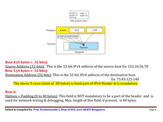
  • 6. Edited & Compiled by: Prof. Krishnananda L, Dept of ECE, Govt SKSJTI Bengaluru Page 6  Row 4 (4 bytes = 32 bits): Source Address (32-bits): This is the 32-bit IPv4 address of the source host Ex: 152.34.56.78 Row 5 (4 bytes = 32 bits): Destination Address (32-bits): This is the 32-bit IPv4 address of the destination host. Ex: 75.83.125.140 The above 5 rows (total of 20 bytes) is fixed part of IPv4 Header & is mandatory. Row 6: Options + Padding (0 to 40 bytes): This field is NOT mandatory to be a part of the header and is used for network testing & debugging. Max. length of this field, if present, is 40 bytes.
  • 7. Edited & Compiled by: Prof. Krishnananda L, Dept of ECE, Govt SKSJTI Bengaluru Page 7 Fragmentation  A datagram can travel through different networks. For ex, if a router connects a LAN to a WAN, it receives a frame in the LAN format and sends a frame in the WAN format. The format and size of the frames vary from one network to another.  Each link-layer protocol (802.3, 802.11 etc) has its own frame format and size. When a datagram is encapsulated in a frame, the total size of the datagram must be less than this maximum size called Maximum Transfer Unit (MTU).  MTU defined by the restrictions imposed by the hardware and software used in the network. The value of MTU varies from one network to other. For ex., the MTU in 802.3 LAN is 1500 bytes.  However, as seen earlier, the maximum size of IP datagram is 65,535 bytes. So, when it is passed through other networks like LAN, the IP datagram needs to be divided into smaller size blocks (called fragments). This process is known as Fragmentation. A datagram may be fragmented several times before it reaches the final destination.
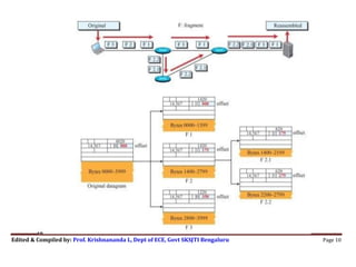
  • 8. Edited & Compiled by: Prof. Krishnananda L, Dept of ECE, Govt SKSJTI Bengaluru Page 8  A datagram can be fragmented by the source host or any router in the path. The reassembly of the datagram is done only by the destination host, after it receives all fragments of a datagram.  When a datagram is fragmented, each fragment has its own header. The host or router that fragments a datagram must change the values of three fields: flags, fragmentation offset, and total length. The rest of the fields are copied from the original datagram. We shall now look into fields of IPv4 Header related to fragmentation Row 2 of the Header:  Flags (3 bits): This field defines 3 flags. The leftmost bit is reserved (not used). The second bit (D bit) is called the do not fragment bit. If its value is 1, the machine must not fragment the datagram. If its value is 0, the datagram can be fragmented if necessary. The third bit (M bit) is called the more fragment bit. If its value is 1, it means the datagram is not the last fragment; there are more fragments after this one. If its value is 0, it means this is the last or only fragment.  Fragmentation Offset (13 bits): This field shows the relative position of this fragment with respect to the whole datagram. It is the offset of the data in the original datagram measured in units of 8 bytes.  Fig 19.6 shows a datagram with a size of 4000 bytes divided into 3 fragments. The bytes in the original datagram are numbered 0 to 3999. The first fragment carries bytes 0 to 1399. The offset for this datagram is 0/8 = 0. The second fragment carries bytes 1400 to 2799; the
  • 9. Edited & Compiled by: Prof. Krishnananda L, Dept of ECE, Govt SKSJTI Bengaluru Page 9 offset value for this fragment is 1400/8 = 175. Finally, the third fragment carries bytes 2800 to 3999. The offset value for this fragment is 2800/8 = 350. Note: The length of the offset field is 13 bits and cannot represent a sequence of bytes greater than 8191. So, choose the size of each fragment so that the first byte number is divisible by 8  Fig. 19.7 shows detailed Fragmentation of Fig.19.6. The value of the ID field is the same in all fragments. In the “flag” field, the M bit is set (logic 1) for all fragments except the last. Also, the value of the offset field for each fragment is shown. Although the fragments arrived out of order at the destination, they can be correctly reassembled.  What happens if a fragment itself is fragmented? In this case, the value of the offset field is always relative to the original datagram. For ex, the second fragment is itself fragmented into two fragments of 800 bytes and 600 bytes, but the offset shows the relative position of the fragments to the original data
  • 10. Edited & Compiled by: Prof. Krishnananda L, Dept of ECE, Govt SKSJTI Bengaluru Page 10
  • 11. Edited & Compiled by: Prof. Krishnananda L, Dept of ECE, Govt SKSJTI Bengaluru Page 11 Example 1: An IPv4 packet has arrived with the first 8 bits as (01000010)2. The receiver discards the packet. Why? Solution: There is an error in this packet. The 4 leftmost bits (0100)2 show the version, which is correct. The next 4 bits (0010)2 show an invalid HLEN value (2). The minimum HLEN value has to be 5, because min. number of bytes in the header must be 20. The packet has been corrupted in transmission. Example 2: In an IPv4 packet, the value of HLEN is (1000)2. How many bytes of options are being carried by this packet? Solution: The HLEN value is 8, the total number of bytes in the header is 8 × 4 = 32 bytes. The first 20 bytes are the base header. So, the next 12 bytes are the options. Example 3: In an IPv4 packet, the value of HLEN is 5, and the value of the total length field is (0028)16. How many bytes of data are being carried by this packet? Solution: The HLEN value is 5. So the header size is 5 × 4 = 20 bytes (no options). The total length is (0028)16 or 40 bytes, which means the packet is carrying 20 bytes of data (40 − 20). Example 4: An IPv4 packet has arrived with the first few hexadecimal digits as shown. (460000320008000005062…)16. Compute the following: a) Header length b) Data length c) How many bytes in the options d) ID of the packet? e) The number of hops packet can travel? f) The data belong to what upper-layer protocol?
  • 12. Edited & Compiled by: Prof. Krishnananda L, Dept of ECE, Govt SKSJTI Bengaluru Page 12 Solution Divide the given data into Row1 bits, Row2 bits etc. Row1 (4 bytes): 46 00 0032 Row2 (4 bytes): 0008 0000 Row3:05 06……  Row1 gives, protocol version, HLEN, service type and total length. a) Header length in bytes = HLEN x 4 = 6x4 = 24 bytes b) Total length is 003216 = 50 bytes. So, data length = total length – header length = 50-24 = 26 bytes c) Header length is 24 bytes. Mandatory 20 bytes. So, Options = 24-20 = 4 bytes  Row2 gives ID, Flags etc d) ID of the packet is: 8  Row3 gives TTL, Protocol type etc e) The TTL field is (05)16. So, packet can travel 5 hops before getting discarded. f) The protocol field has the value (06)16, so, the upper-layer protocol is TCP. Example 5: Checksum calculation for an IPv4 header without options. Solution: The header is divided into 16-bit sections. All the sections are added and the sum is complemented after wrapping the leftmost digit. The result is inserted in the checksum field. The calculation of wrapped sum and checksum can also be done hexadecimal. Wrapped Sum= Sum Mod FFFF Checksum=FFFF—Wrapped Sum
  • 13. Edited & Compiled by: Prof. Krishnananda L, Dept of ECE, Govt SKSJTI Bengaluru Page 13
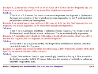
  • 14. Edited & Compiled by: Prof. Krishnananda L, Dept of ECE, Govt SKSJTI Bengaluru Page 14 Example 6. A packet has arrived with an M bit value of 0. Is this the first fragment, the last fragment, or a middle fragment? Do we know if the packet was fragmented? Solution If the M bit is 0, it means that there are no more fragments; the fragment is the last one. However, we cannot say if the original packet was fragmented or not. A nonfragmented packet is considered the last fragment. Example 7. A packet has arrived with an M bit value of 1. Is this the first fragment, the last fragment, or a middle fragment? Do we know if the packet was fragmented? Solution If the M bit is 1, it means that there is at least one more fragment. This fragment can be the first one or a middle one, but not the last one. The packet is definitely fragmented. Example 8. A packet has arrived with an M bit value of 1 and a fragmentation offset value of 0. Is this the first fragment, the last fragment, or a middle fragment? Solution Because the M bit is 1, it is either the first fragment or a middle one. Because the offset value is 0, it is the first fragment. Example 9. A packet has arrived in which the offset value is 100. What is the number of the first byte? Do we know the number of the last byte? Solution To find the number of the first byte, we multiply the offset value by 8. This means that the first byte number is 800. We cannot determine the number of the last byte unless we know the length of the data.
  • 15. Edited & Compiled by: Prof. Krishnananda L, Dept of ECE, Govt SKSJTI Bengaluru Page 15 Example 10. A packet has arrived in which the offset value is 100, the value of HLEN is 5, and the value of the total length field is 100. What are the numbers of the first byte and the last byte? Solution The first byte number is 100 × 8 = 800. The total length is 100 bytes, and the header length is 20 bytes (5 × 4), which means that there are 80 bytes in this datagram. If the first byte number is 800, the last byte number must be 879.
  • 16. Computer Communication Networks- 17EC64 Module 3 WLANs Compiled by: Prof. Krishnananda L, Dept of ECE, Govt SKSJTI, Bengaluru Page 16 19.1.4 Security of IPv4 Datagrams  No security was provided for the IPv4 protocol when it was originally developed.  There are three security issues/attacks applicable to the IP protocol: Packet sniffing, packet modification, and IP spoofing. 1) Packet Sniffing An intruder may intercept an IP packet and make a copy of it. Packet sniffing is a passive attack, in which the attacker does not change the contents of the packet. This type of attack is very difficult to detect because the sender and the receiver may never know that the packet has been copied. One solution is encryption of the packet. The attacker may still sniff the packet, but the content is cannot be deciphered. 2) Packet Modification The second type of attack is to modify the packet. The attacker intercepts the packet, changes its contents, and sends the new packet to the receiver. The receiver believes that the packet is coming from the original sender. This type of attack can be detected using a data integrity mechanism. 3) IP Spoofing An attacker can masquerade as somebody else and create an IP packet that carries the source address of another computer. An attacker can send an IP packet to a bank pretending that it is coming from one of the customers. This type of attack can be prevented using an origin authentication mechanism. IPSec (IP Security Protocol) The IP packets can be protected from the previously mentioned attacks using a protocol called IPSec (IP Security). This protocol, which is used in conjunction with the IP protocol, creates a connection-oriented service between two entities in which they can exchange IP packets without worrying about the attacks. IPSec provides the following four services:
  • 17. Computer Communication Networks- 17EC64 Module 3 WLANs Compiled by: Prof. Krishnananda L, Dept of ECE, Govt SKSJTI, Bengaluru Page 17 ❑ Defining Algorithms and Keys. The two entities that want to create a secure channel between themselves can agree on some available algorithms and keys to be used for security purposes. ❑ Packet Encryption. The packets exchanged between two parties can be encrypted for privacy using one of the encryption algorithms and a shared key agreed upon. This makes the packet sniffing attack useless. ❑ Data Integrity. Data integrity guarantees that the packet is not modified during the transmission. If the received packet does not pass the data integrity test, it is discarded. This prevents the second attack, packet modification, described above. ❑ Origin Authentication. IPSec can authenticate the origin of the packet to be sure that the packet is not created by an imposter. This can prevent IP spoofing attacks.