SlideShare a Scribd company logo
N.Jagadish kumar
Assistant professor-IT
1
FUNDAMENTALS & LINK LAYER
2
Overview
3
Building a network
A network is a set of devices connected by a media link
Devices are often called as nodes
They are the serial lines connected by dumb terminals to
mainframe computer
Difference=>Carry many different types of data and
support a wide range of applications
Data Communications
4
• Data – facts, concepts, and instructions
• Data – Information presented in whatever form is agreed
upon by the parties creating and using the data
• Represented by binary information units (in the form of 0s
and 1s)
• Data Communications – Exchange of data between two
devices via some form of transmission medium such as a
wire cable
Effectiveness of Data Communications
5
Effectiveness of a data communications system
depends on three fundamental characteristics
 Delivery : The system must deliver data to the correct
destination. Data must be received by the intended device or
user and only by that device or user
 Accuracy: The system must deliver the data accurately. Data
that have been altered in transmission and left uncorrected are
unusable
 Timeliness: The system must deliver data in a timely manner.
Data delivered late are useless. Delivering the data in the same
order that they are produced and without significant delay
(real time transmission)
6
Five components of datacommunication
Message:
Information to be
communicated.
Consist of text, numbers,
pictures, sound or video -
combination
7
Five components of datacommunication
Sender:
Device that sends the data
message-
May be computer, workstation.
telephone handset, video
camera and etc.
8
Five components of data communication
Receiver:
The device that receives the
message.
Can be computer, work station,
telephone handset, television
and so on.
9
Five components of data communication
Medium:
Physical path by which a
message travels from sender to
receiver. Eg :Twisted pair wire,
coaxial cable, fibre optic cable or
radio waves
10
Five components of data communication
Protocol:
Set of rules that governs data
communication. It represents an
agreement between the
communicating devices.
Without a protocol, two devices
may be connected but not
communicating
Data Representation
11
Information Today comes in different forms
such as text, numbers, images, audio and
video
Text:
Represented as a bit pattern, a sequence of bits 0s
or 1s. Different codes are used
ASCII (7 bits per symbol)
Extended ASCII (8 bits per symbol)
Unicode (16 bits – supports different languages)
ISO (32 bits)
Data Representation
12
Numbers:
Converted to a binary number – to simplify the
mathematical operations
Images:
Represented by bit patterns
Each pixel is assigned a bit pattern
Black and White Image – 1 bit per pixel
Gray scale images – depends on number of levels in gray
scale
Colour images: Each pixel has 3 bit patterns (RGB)
• Audio / Video:
– Converted in to Analog/Digital
Direction of data flow
13
Simplex
Simplex – unidirectional; one transmits, other receives
14
Half-duplex
Half-duplex – each can transmit/receive; communication must alternate
15
Full-duplex
Full-duplex – both can transmit/receive simultaneously
Networks
16
Set of devices (nodes) connected by media.
17
Requirements
The requirements to build a network are,
Perspectives
Scalable Connectivity
Cost effective resource sharing
Support for common services
Interoperability
Managebility
Performance
Connectivity=> Connections among a set of computers
Links and nodes
Types of links=> point to point link, multipoint link
Applications
• Peer-Peer model:
– No fixed clients or servers
– Each host can act as both client & server
• Examples: Napster, Gnutella, KaZaA
18
Applications
19
WWW
• Instant Messaging (Internet chat, text messaging on
cellular phones)
• Peer-to-Peer
• Internet Phone
• Video-on-demand
• Distributed Games
• Remote Login (Telnet)
• File Transfer
Network Criteria
20
 Performance
Can be measured by transit time and response time. Affected
by number of users, type of medium, connected HW/SW
 Reliability
Measured by frequency of failure, recovery time, robustness in
a catastrophe
 Security – protection from unauthorized access, viruses /
worms
Line Configuration
21
The way two or more communication devices attach to a
link
Link – Physical communication pathway that transfer data
from one device to another
Two possible line configurations
Point-to-point
Multipoint
22
Point-to-point connection
23
Multipoint connection
Topology
24
Physical or logical arrangement
Topology of a network is the geometric representation
of the relationship of all the links and linking devices
to one another
 Basic types: Mesh, star, bus, ring,hybrid
25
Categories of topology
Mesh Topology
 Dedicated point-to-point links to
every other device
 n(n-1)/2 links an each device will
have n-1 I/O ports
Advantages:
 Dedicated links – no traffic
problems
 Robust
 Privacy/Security
 Easy fault identification and
isolation
Disadvantages:
 More amount of cabling and I/O
ports requirement
 Installation and reconnection is
difficult
 Expensive
26
Star Topology
Dedicated point-to-point links to
central controller (hub)
Controller acts as exchange
Advantages
less expensive
robustness
Disadvantages
More cabling requirement than ring
and bus topologies
27
Bus Topology
Multipoint configuration
One cable acts as a backbone to link all devices
Advantages : Ease of installation, less cabling
Disadvantages : Difficult reconnection and fault
isolation, a fault/break in the bus cable stops all
transmission
28
Ring Topology
Dedicated point-to-point configuration to neighbours
Signal is passed from device to device until it reaches destination
Each device functions as a repeater
Advantages : easy to install and reconfigure
Disadvantages :limited ring length and no: of devices; break
in a ring can disable entire network
29
Categories of Networks
30
 Based on size, ownership, distance covered, and physical
architecture
Local Area Network (LAN) – smaller geographical area
Metropolitan Area Network (MAN) – network extended over
an entire city
Wide Area Network (WAN) – large geographical area
31
Categories of networks
32
LAN
Privately owned and links the devices in a
single office, building or campus
33
LAN
34
MAN
Designed to extend over an entire city – May be a single
network such as cable television network – may be a means
of connecting a number of LANS into a larger network
Metropolitan Area Network (MAN)
35
home
cable headend
cable distribution
network (simplified)
Typically 500 to 5,000 homes
A Cable TV Network is an example of a MAN
36
WAN
Provides long distance transmission of data, voice, image
and video information over large geographic areas – a
country/continent/world
Protocols and Standards
37
Protocols:
Set of rules that governs data communications
Defines what is communicated, how it is communicated,
and when it is communicated
Key elements
Syntax : Structure/ format of data –order in which it is presented
Semantics : meaning of each section of bits- how pattern to be
interpreted – What action to be taken
Timing: When data to be sent and how fast they can be sent
Protocols and Standards
38
Standards:
Essential in creating and maintaining an open and
competitive market for equipment manufacturers and in
guaranteeing national and international interoperability
of data and telecommunications technology and
processes
– De facto: Standards that have not been approved by an
organized body but have been adopted as standards
through widespread use
– De jure: legislated by an officially recognized body
Protocols and Standards
39
 Standards Organizations
• International organization for Standardization (ISO)
• International Telecommunication Union –
Telecommunication Standards Sector (ITU-T)
• American National Standards Institute (ANSI)
Institute of Electrical and Electronics Engineers (IEEE)
• Electronic Industries Assoctiation (EIA)
 Regulatory Agencies
Federal Communication Commission (FCC)
 Internet Standards
Internet Draft
Request for Comment (RFC)
ISO/OSI MODEL
ISO/OSI MODEL
 The Open Systems Interconnection (OSI) architecture
has been developed by the International Organization for
Standardization (ISO) to describe the operation and design
of layered protocol architectures.
 This forms a valuable reference model and defines much
of the language used in data communications.
ISO/OSI MODEL
42
FUNCTIONS OF LAYERS
Describes a seven-layer abstract reference model for a
network Architecture.
Purpose of the reference model was to provide a framework
for the development of protocols
43
 PHYSICAL LAYER
43
FUNCTIONS OF LAYERS
Physical characteristics of interfaces and media
Representation of bits
Data rate
Synchronization of bits:
DATALINK LAYER
Framing
Physical Addressing
Flow Control
Error control& Access control
44
FUNCTIONS OF LAYERS
NETWORK LAYER
Logical Addressing
Routing
TRANSPORT LAYER
Service-point (port) addressing
Segmentation and reassembly
Connection control
Flow control
Error Control
45
FUNCTIONS OF LAYERS
SESSION LAYER
 Dialog Control
Synchronization
PRESENTATION LAYER
Translation
Encryption
Compression
APPLICATION LAYER
Network Virtual terminal
File transfer, access and management
Mail services & Directory services
46
Switched Network
Long distance transmission
Don’t bother about the content of data
Transfers the data until it reaches the destination
Types=> packet switched and circuit switched
47
Packet switching
Used when the users are need of intermittent channel usage
Messages are broken into individual small packets
Switch to switch packet transmission
Handles traffic well
Approaches=> datagram and virtual circuit
48
Datagram=>connection-less
Disadvantages=>
Suffers from lot of overhead
The packets are not reassembled at the receiver
Virtual circuit=> connection oriented
Consist of 3 phases=>
Establishment phase=> set up connection and ensures QoS
Data transfer phase=> performs error control, flow control services
Connection release phase=>Connection termination
49
Datagram approach
50
Virtual circuit approach
51
Comparison
S.no Virtual Circuit Datagram
1 Circuit setup is required Circuit setup is not
required
2 Each packet contains a short
VC number as address
Each packet contains full
source and destination
address
3 Route chosen when VC is
setup and all packets follow
this route
Each packet is routed
independently
4 All packets are lost incase of
router failure
Only crashed packets are
lost
5 Congestion control is easy
using buffers
Difficult congestion
control
52
Circuit Switching=>
 End to end path setup beginning of a session
Dedicated to an application
And then released at the end of the session
Example=> Telephone system
Message Switching=>
Data stored at the switching office and then
forwarded later
Uses store and forward network
Example=> Telegraph system
53
Addressing
It uses four levels of addresses,
Physical(link) addresses=> defined by its LAN
or WAN
Logical(IP)addresses=>universal
communications
Port addresses=>label assigned to the
communication process through telnet and FTP
Specific addresses=>designed by users for some
application
54
TCP/IP layers and its addresses
Specific Addresses
Port Address
Logical Address
Physical Address
55
Network software
Socket Application Programming Interface
Socket=>interface between the application layer
and transport layer
Also referred as API between application and
network
Associated with host address and a port address
Host address=>IP address of a host where client
and server program is loaded
Port address=>communication port used by the
client or server program
56
Syntaxes for Socket Connection
Socket creation=> int socket(int family, int type, int
protocol);
Binding=>int bind(int sd,struct sockaddr *name, int
namelen);
Listening=> int listen(int sd, int backlog);
Accepting=> int accept(int sd, struct *addr, int
*addrlen);
Closing=>int close(int sd);
57
Protocol Implementation
OS uses process or thread=>communication
Implementation=>
Process per protocol model
Process per message model
Message Buffers=>
58
Performance
Measured in various parameters
Bandwidth=> measured in hertz and bps
Throughput=>Measures the speed of data
transmission
Latency=>Time required for sending a message
to reach destination
Bandwidth delay product=>number of bits that
can fill the channel
Jitter=>Data packets reaching at receiver at
different times
Transmission Media
Transmission media can be divided into two broad categories
 Guided
 Unguided
Guided media
It includes twisted-pair cable, coaxial cable, and fiber-optic
cable.
Guided media, which are those that provide a conduit from one
device to another.
Unguided media
It is usually air.
Transmission Media
Coaxial cable
Coaxial cable carries signals of higher frequency ranges than
twisted pair cable.
 It has a central core conductor of solid or stranded wire enclosed
in an insulating sheath.
This in turn encased in an outer conductor of metal foil ,braid or a
combination of the two.
61
Transmission Media
Fiber Optic Cable.
A fiber optic cable is made of glass or plastic and transmit signals
in the form of light.
There are two modes for propagating light along optical
channels.
 Multimode
 Single mode.
LINE CODING&SCHEMES
Line Coding is the process of converting binary data , a
sequence of bits , to a digital signal
 Unipolar encoding uses only one voltage level.
LINE CODING&SCHEMES
Polar encoding uses two voltage levels (positive and negative).Polar encoding uses two voltage levels (positive and negative).
POLAR ENCODING&SCHEMES
NRZ-LNRZ-L :The level of the signal is dependent upon the:The level of the signal is dependent upon the state of thestate of the
bitbit
NRZ-I:NRZ-I: The signal isThe signal is inverted if a 1 is encounteredinverted if a 1 is encountered..
RZ encoding:
POLAR ENCODING&SCHEMES
Manchester encodingManchester encoding: the: the transition at the middle of the bittransition at the middle of the bit
is used for both synchronization and bit representation.is used for both synchronization and bit representation.
66
Differential Manchester encoding:Differential Manchester encoding:
TheThe transition at the middletransition at the middle of the bit is used only forof the bit is used only for
synchronization.synchronization.
The bit representation is defined by theThe bit representation is defined by the inversion or non-inversion or non-
inversioninversion at theat the beginning of the bitbeginning of the bit..
POLAR ENCODING&SCHEMES
BIPOLAR ENCODING
Bipolar AMI encoding:Bipolar AMI encoding: Use three levels: positive, zero, andUse three levels: positive, zero, and
negative.negative.
68
Modem Standards
The term modem is a composite word that refers to the two
functional entities that make up the device; a signal modulator
and a signal demodulator.
A modulator creates a bandpass analog signal from binary
data.
A demodulator recovers the binary data from the
modulated signal.
TELEPHONE MODEMS
Traditional telephone lines can carry frequencies between 300
and 3300 HZ, giving them BW of 3000 Hz.
The effective BW of a telephone line being used for data
transmission is 2400 Hz,covering the range from 600 to 3000
Hz.
Modem standards
V-series standards published by the ITU-T.
V.32:
The V.32 calls for 32-QAM with a baud rate of 2400.
Because only 4 bits of each pentabit represents data, the
resulting speed is 4*2400=9600
V.32 bits:
The V.32 bits modem support 14,400-bps transmission. The
V.32 bits uses 128-QAM transmission.
V.34 bits:
The V.34 bits modem support 28,800-bps transmission
with a 960-point constellation to a bit rate of 33,600
with a 1664-point constellation.
Traditional modems
In traditional modems data exchange is between two
computers, A and B,through digital telephone network.
After modulation by the modem, an analog signal
reaches the telephone company Switching station.
It is sampled and digitized to be passed through the
digital network.
The quantization noise introduced in the signal at the
sampling point limits the data rate according to the
capacity. This limit is 33.6 Kbps.
Traditional modems
56K Modems
Communication is via the Internet.
 In Uploading, the analog signal must still be
sampled at the switching station, which means the
data rate in the uploading is limited to33.6 Kbps.
There is no sampling in downloading. Data rate in
downloading is 56Kbps
56K Modems
RS 232 INTERFACE
RS 232 is a standard interface by EIA and RS232C is the
latest version of this interface.
RS232 standard follows –ve logic.
 Logic1 is represented by negative voltage.
Logic0 is represented by +ve voltage.
Level 1 varies from -3 to -15v and level 0 varies from 3 to15v
76
Data Link Layer design issues
Services provided to the network layer=>
Transfers the data from the network layer on the
source to network layer on the destination
The important services are,
unacknowledged connectionless services
Acknowledged connection service
Acknowledged connection-oriented service
77
Framing=> separates a message from one source to a
destination or from other messages to other destinations
Fixed size framing
Variable size framing
o Character oriented protocol=> byte stuffing
o Bit oriented protocol=>data as sequence of bits and
interpreted by the upper layer as text, graphics, audio,
etc.
78
Error Control
Ensures proper sequencing and safe delivery of
frames at destination
An acknowledgement is send by destination node
Positive acknowledgement=>frame is successfully
delivered
Negative acknowledgement=>frame not sent and the
frame is to be retransmitted
79
Flow control =>the data flow is regulated
Includes a feedback mechanism requesting transmitter
to retransmit the data
Damaged frames
Lost frame
Lost acknowledgement frames
Most common retransmission technique=>
ARQ(Automatic repeat request)
80
Error Detection & Correction
Introduction
Data can be corrupted during transmission
For reliable communication, errors must be detected and
corrected
Error
 Bits flow from one point to another
 They subject to unpredictable changes because of
interference is rightly called as an error
81
Error Detection
Types of Errors
 Single-Bit Errors
only one bit in the data unit has changed
82
Error Detection
 Burst Errors of length ‘n’:
2 or more bits in the data unit have changed
83
Error Detection
Error Detection
Sender transmits every data unit twice
Receiver performs bit-by-bit comparison between that two
versions of data
Any mismatch would indicate an error, which needs error
correction.
Redundancy
Shorter group of bits may be appended to the end of each unit
84
Error Detection
Types of Redundancy Checks
Parity Check
 Simple Parity Check
Two Dimensional Parity Check / Longitudinal Redundancy
Check (LRC)
Cyclic Redundancy Check (CRC)
Check Sum
85
Parity check
Parity
A redundant bit called Parity Bit is added to every data unit
Even Parity: total number of 1‘s in the data unit becomes even
Odd Parity: total number of 1‘s in the data unit becomes odd
86
LONGTITUDINAL REDUNDANCY CHECK
LRC - Performance
Detects all burst errors up to length n (number of
columns)
If two bits in one data unit are damaged and two bits in
exactly same positions in another data unit are also
damaged.
Now the checker will not detect an error
87
LONGTITUDINAL REDUNDANCY CHECK
88
Cyclic redundancy check
Powerful error detection scheme
Rather than addition, binary division is used
A sequence of redundant bits, called CRC or CRCremainder
is appended to the data unit
At the receiver side, the incoming data unit is divided by the
same predetermined number.
If there is no remainder, the data unit is accepted
If there is a remainder, the receiver indicates that the data unit
has been damaged during transmission
89
Cyclic redundancy check
90
Error Correction
Error Correction-Hamming Code
Hamming Code uses the relationship between data and
redundancy bits.
For example: a 7-bit ASCII code requires 4 redundancy
bits, which are placed in positions 1, 2, 4 and 8 i.e.
x0,x1,x2,x3 and so on.
91
Error Correction –Hamming Code
In the Hamming Code, each bit for one combination of
data bits as below:
r1: bits 1, 3, 5, 7, 9, 11
r2: bits 2, 3, 6, 7, 10, 11
r3: bits 4, 5, 6, 7
r4: bits 8, 9, 10, 11
92
Error Correction –Hamming Code
93
Data Link Control
 Flow Control
 Error Control
Flow Control:
How much data sender can transmit before receiving the
acknowledgement
Error Control:
Error Detection + Error Correction
ARQ
o Any time, an error is discovered in an exchange, specified frames
are retransmitted
94
Flow and Error Control Mechanisms
Stop and Wait ARQ
 Go-Back ARQ
Selective Repeat ARQ
Stop and Wait ARQ
 Simplest flow and error control mechanism
 The sending device keeps a copy of the last frame
transmitted until it receives an acknowledgement
 Frames - alternately numbered as 0 and 1
95
Stop-and-Wait
 Sender keeps a copy of the last frame until it
receives an acknowledgement.
 For identification, both data frames and
acknowledgements (ACK) frames are numbered
alternatively 0 and 1.
 Sender has a control variable (S) that holds the
number of the recently sent frame. (0 or 1)
 Receiver has a control variable ® that holds the
number of the next frame expected (0 or 1).
 Sender starts a timer when it sends a frame. If an
ACK is not received within a allocated time
period, the sender assumes that the frame was
lost or damaged and resends it
 Receiver send only positive ACK if the frame is
intact.
 ACK number always defines the number of the
next expected frame
96
Stop-and-Wait ARQ, lost ACK frame
When a receiver receives a
damaged frame, it discards
it and keeps its value of R.
After the timer at the
sender expires, another
copy of frame 1 is sent.
97
Stop-and-Wait, lost ACK
frame
• If the sender receives a
damaged ACK, it
discards it.
• When the timer of the
sender expires, the
sender retransmits
frame 1.
• Receiver has already
received frame 1 and
expecting to receive
frame 0 (R=0).
Therefore it discards
the second copy of
frame 1.
98
Stop-and-Wait, delayed ACK
frame • The ACK can be delayed
at the receiver or due to
some problem
• It is received after the
timer for frame 0 has
expired.
• Sender retransmitted a
copy of frame 0.
However, R =1 means
receiver expects to see
frame 1. Receiver
discards the duplicate
frame 0.
• Sender receives 2 ACKs,
it discards the second
ACK.
99
Piggybacking
• A method to combine a
data frame with ACK.
• Station A and B both
have data to send.
• Instead of sending
separately, station A
sends a data frame that
includes an ACK.
• Station B does the same
thing.
• Piggybacking saves
bandwidth.
100
Disadvantage of Stop-and-Wait
• In stop-and-wait, at any point in time, there is only one frame
that is sent and waiting to be acknowledged.
• This is not a good use of transmission medium.
• To improve efficiency, multiple frames should be in transition
while waiting for ACK.
• Two protocol use the above concept,
– Go-Back-N ARQ
– Selective Repeat ARQ
101
Go-Back-N ARQ
We can send up to W frames before worrying about ACKs.
We keep a copy of these frames until the ACKs arrive.
This procedure requires additional features to be added to Stop-
and-Wait ARQ.
102
Sequence Numbers
• Frames from a sender are numbered sequentially.
• We need to set a limit since we need to include the sequence
number of each frame in the header.
• If the header of the frame allows m bits for sequence number,
the sequence numbers range from 0 to 2 m
– 1. for m = 3,
sequence numbers are: 1, 2, 3, 4, 5, 6, 7.
• We can repeat the sequence number.
• Sequence numbers are:
0, 1, 2, 3, 4, 5, 6, 7, 0, 1, 2, 3, 4, 5, 6, 7, 0, 1, …
103
Sender Sliding Window
• At the sending site, to hold
the outstanding frames until
they are acknowledged, we
use the concept of a
window.
• The size of the window is at
most 2m
-1 where m is the
number of bits for the
sequence number.
• Size of the window can be
variable, e.g. TCP.
• The window slides to
include new unsent frames
when the correct ACKs are
received
104
Receiver Sliding Window
• Size of the window at the
receiving site is always 1 in
this protocol.
• Receiver is always looking
for a specific frame to
arrive in a specific order.
• Any frame arriving out of
order is discarded and
needs to be resent.
• Receiver window slides as
shown in fig. Receiver is
waiting for frame 0 in part
a.
105
Control Variables
• Sender has 3 variables: S, SF, and SL
• S holds the sequence number of recently sent frame
• SF holds the sequence number of the first frame
• SL holds the sequence number of the last frame
• Receiver only has the one variable, R, that holds the sequence number of
the frame it expects to receive. If the seq. no. is the same as the value of
R, the frame is accepted, otherwise rejected.
106
Go-Back-N ARQ, normal operation
• The sender keeps track of the outstanding frames and updates the
variables and windows as the ACKs arrive.
107
Go-Back-N ARQ, lost frame
• Frame 2 is lost
• When the receiver
receives frame 3, it
discards frame 3 as
it is expecting
frame 2 (according
to window).
• After the timer for
frame 2 expires at
the sender site, the
sender sends frame
2 and 3. (go back
to 2)
108
Go-Back-N ARQ, damaged/lost/delayed ACK
• If an ACK is damaged/lost, we can have two situations:
• If the next ACK arrives before the expiration of any timer, there
is no need for retransmission of frames because ACKs are
cumulative in this protocol.
• If ACK1, ACK2, and ACk3 are lost, ACK4 covers them if it
arrives before the timer expires.
• If ACK4 arrives after time-out, the last frame and all the frames
after that are resent.
• Receiver never resends an ACK.
• A delayed ACK also triggers the resending of frames
109
Go-Back-N ARQ, sender window size
• Size of the sender window must be less than 2 m
. Size of the receiver is
always 1. If m = 2, window size = 2 m
– 1 = 3.
• Fig compares a window size of 3 and 4.
Accepts as
the 1st
frame in
the next
cycle-an
error
110
Selective Repeat ARQ, sender and receiver
windows• Go-Back-N ARQ simplifies the process at the receiver site. Receiver only keeps track of
only one variable, and there is no need to buffer out-of-order frames, they are simply
discarded.
• However, Go-Back-N ARQ protocol is inefficient for noisy link. It bandwidth
inefficient and slows down the transmission.
• In Selective Repeat ARQ, only the damaged frame is resent. More bandwidth efficient
but more complex processing at receiver.
• It defines a negative ACK (NAK) to report the sequence number of a damaged frame
before the timer expires.
111
Selective Repeat ARQ, lost frame
• Frames 0 and 1 are accepted
when received because they
are in the range specified by
the receiver window. Same
for frame 3.
• Receiver sends a NAK2 to
show that frame 2 has not
been received and then
sender resends only frame 2
and it is accepted as it is in
the range of the window.
112
Selective Repeat ARQ, sender window size
• Size of the sender and receiver windows must be at most one-half of 2 m
. If m = 2,
window size should be 2 m
/2 = 2. Fig compares a window size of 2 with a window size
of 3. Window size is 3 and all ACKs are lost, sender sends duplicate of frame 0, window
of the receiver expect to receive frame 0 (part of the window), so accepts frame 0, as the
1st
frame of the next cycle – an error.

More Related Content

What's hot (20)

Switching
SwitchingSwitching
Switching
Shankar Gangaju
 
Network layer logical addressing
Network layer logical addressingNetwork layer logical addressing
Network layer logical addressing
Sri Manakula Vinayagar Engineering College
 
Lan technologies
Lan technologiesLan technologies
Lan technologies
Manusha Dilan
 
Routing protocols
Routing protocolsRouting protocols
Routing protocols
Sourabh Goyal
 
Why we need ipv6...
Why we need ipv6...Why we need ipv6...
Why we need ipv6...
Adii Shah
 
Easy IP Addressing and Subnetting Manual for Starters
Easy IP Addressing and Subnetting Manual for StartersEasy IP Addressing and Subnetting Manual for Starters
Easy IP Addressing and Subnetting Manual for Starters
S Khawaja
 
What is Ethernet
What is EthernetWhat is Ethernet
What is Ethernet
Simplilearn
 
Ch 19 Network-layer protocols Section 1
Ch 19  Network-layer protocols Section 1Ch 19  Network-layer protocols Section 1
Ch 19 Network-layer protocols Section 1
Hossam El-Deen Osama
 
Transport layer
Transport layer Transport layer
Transport layer
Mukesh Chinta
 
MANET VS VANET
MANET VS VANETMANET VS VANET
MANET VS VANET
MAHESHWARAND5
 
IP addressing and Subnetting PPT
IP addressing and Subnetting PPTIP addressing and Subnetting PPT
IP addressing and Subnetting PPT
Pijush Kanti Das
 
Mac layer
Mac  layerMac  layer
Mac layer
Shubham Kansal
 
Introduction to TCP/IP
Introduction to TCP/IPIntroduction to TCP/IP
Introduction to TCP/IP
Michael Lamont
 
Peer to peer
Peer to peerPeer to peer
Peer to peer
Raymond Douglas
 
Osi model
Osi modelOsi model
Osi model
dhawal mehta
 
Layer 2 & layer 3 switching
Layer 2 & layer 3 switchingLayer 2 & layer 3 switching
Layer 2 & layer 3 switching
Muhd Mu'izuddin
 
W-LAN (Wireless Local Area Network)
W-LAN (Wireless Local Area Network)W-LAN (Wireless Local Area Network)
W-LAN (Wireless Local Area Network)
Parvesh Taneja
 
ipv4 & ipv6
ipv4 & ipv6ipv4 & ipv6
ipv4 & ipv6
Burhan Ahmed
 
Network architecture
Network architectureNetwork architecture
Network architecture
Dr. Shalini Pandey
 
Cisco CCNA- How to Configure Multi-Layer Switch
Cisco CCNA- How to Configure Multi-Layer SwitchCisco CCNA- How to Configure Multi-Layer Switch
Cisco CCNA- How to Configure Multi-Layer Switch
Hamed Moghaddam
 

Similar to Computer Network Fundamentals (20)

CIT 3212 Computer Networks Week 1 Notes.pptx
CIT 3212 Computer Networks Week 1 Notes.pptxCIT 3212 Computer Networks Week 1 Notes.pptx
CIT 3212 Computer Networks Week 1 Notes.pptx
winebaldbanituze
 
Skr+3200+chapter+1+(kweh)
Skr+3200+chapter+1+(kweh)Skr+3200+chapter+1+(kweh)
Skr+3200+chapter+1+(kweh)
Ammar Shafiq
 
Chapgggggg&gggggggggggggggghhghhghter 5.pptx
Chapgggggg&gggggggggggggggghhghhghter 5.pptxChapgggggg&gggggggggggggggghhghhghter 5.pptx
Chapgggggg&gggggggggggggggghhghhghter 5.pptx
seyfadinabdela42
 
Data computer networks from rajeev institute of technology
Data computer networks from rajeev institute of technologyData computer networks from rajeev institute of technology
Data computer networks from rajeev institute of technology
harshithamandya49
 
Module_1 Final.pptx _Behrouz A. Forouzan, Data Communications and Networking,...
Module_1 Final.pptx _Behrouz A. Forouzan, Data Communications and Networking,...Module_1 Final.pptx _Behrouz A. Forouzan, Data Communications and Networking,...
Module_1 Final.pptx _Behrouz A. Forouzan, Data Communications and Networking,...
lakshmiuma91
 
Data Communications and Networking By Behrouz A.Forouzan1-2.pdf
Data Communications and Networking By Behrouz A.Forouzan1-2.pdfData Communications and Networking By Behrouz A.Forouzan1-2.pdf
Data Communications and Networking By Behrouz A.Forouzan1-2.pdf
AhmadSamak1
 
Module-1.pptx Computer Networks BCS502 module-1 ppt
Module-1.pptx Computer Networks BCS502 module-1 pptModule-1.pptx Computer Networks BCS502 module-1 ppt
Module-1.pptx Computer Networks BCS502 module-1 ppt
ambikavenkatesh2
 
ppt_dcn.pdf
ppt_dcn.pdfppt_dcn.pdf
ppt_dcn.pdf
MouDhara1
 
ppt_dcn.pptx networks networks security of networks
ppt_dcn.pptx networks networks security of networksppt_dcn.pptx networks networks security of networks
ppt_dcn.pptx networks networks security of networks
DrNeetuSharma5
 
Lecture 01
Lecture 01Lecture 01
Lecture 01
Anwal Mirza
 
Chapter 2.pptx
Chapter 2.pptxChapter 2.pptx
Chapter 2.pptx
MDKhalik1
 
Data Representation in Data Communication (1).pptx
Data Representation in Data Communication (1).pptxData Representation in Data Communication (1).pptx
Data Representation in Data Communication (1).pptx
moviebro1
 
Chapters1&2.pdf
Chapters1&2.pdfChapters1&2.pdf
Chapters1&2.pdf
MelatEndashaw
 
UNIT 1 - Introduction to Data Communication & Computer Networks.pptx
UNIT 1 - Introduction to Data Communication & Computer Networks.pptxUNIT 1 - Introduction to Data Communication & Computer Networks.pptx
UNIT 1 - Introduction to Data Communication & Computer Networks.pptx
sameernsn1
 
Introduction to computer_lec_05_fall_2018
Introduction to computer_lec_05_fall_2018Introduction to computer_lec_05_fall_2018
Introduction to computer_lec_05_fall_2018
Ramadan Babers, PhD
 
Ch 1 network
Ch 1  networkCh 1  network
Ch 1 network
MohamedAbdELhamed35
 
Unit-1 _weqeqeqweqweqweweqweqweqwweCCN.ppt
Unit-1 _weqeqeqweqweqweweqweqweqwweCCN.pptUnit-1 _weqeqeqweqweqweweqweqweqwweCCN.ppt
Unit-1 _weqeqeqweqweqweweqweqweqwweCCN.ppt
KalpeshMahajan23
 
Introduction to computer networks
Introduction to computer networksIntroduction to computer networks
Introduction to computer networks
veeravanithaD
 
Network Fundamentals1.pptx
Network Fundamentals1.pptxNetwork Fundamentals1.pptx
Network Fundamentals1.pptx
sairakesh41
 
Chapter 1.pptx for ece department anf axjaxakxanxakxnzxknzxzaxnz
Chapter 1.pptx for ece department anf axjaxakxanxakxnzxknzxzaxnzChapter 1.pptx for ece department anf axjaxakxanxakxnzxknzxzaxnz
Chapter 1.pptx for ece department anf axjaxakxanxakxnzxknzxzaxnz
wakosafayi
 
CIT 3212 Computer Networks Week 1 Notes.pptx
CIT 3212 Computer Networks Week 1 Notes.pptxCIT 3212 Computer Networks Week 1 Notes.pptx
CIT 3212 Computer Networks Week 1 Notes.pptx
winebaldbanituze
 
Skr+3200+chapter+1+(kweh)
Skr+3200+chapter+1+(kweh)Skr+3200+chapter+1+(kweh)
Skr+3200+chapter+1+(kweh)
Ammar Shafiq
 
Chapgggggg&gggggggggggggggghhghhghter 5.pptx
Chapgggggg&gggggggggggggggghhghhghter 5.pptxChapgggggg&gggggggggggggggghhghhghter 5.pptx
Chapgggggg&gggggggggggggggghhghhghter 5.pptx
seyfadinabdela42
 
Data computer networks from rajeev institute of technology
Data computer networks from rajeev institute of technologyData computer networks from rajeev institute of technology
Data computer networks from rajeev institute of technology
harshithamandya49
 
Module_1 Final.pptx _Behrouz A. Forouzan, Data Communications and Networking,...
Module_1 Final.pptx _Behrouz A. Forouzan, Data Communications and Networking,...Module_1 Final.pptx _Behrouz A. Forouzan, Data Communications and Networking,...
Module_1 Final.pptx _Behrouz A. Forouzan, Data Communications and Networking,...
lakshmiuma91
 
Data Communications and Networking By Behrouz A.Forouzan1-2.pdf
Data Communications and Networking By Behrouz A.Forouzan1-2.pdfData Communications and Networking By Behrouz A.Forouzan1-2.pdf
Data Communications and Networking By Behrouz A.Forouzan1-2.pdf
AhmadSamak1
 
Module-1.pptx Computer Networks BCS502 module-1 ppt
Module-1.pptx Computer Networks BCS502 module-1 pptModule-1.pptx Computer Networks BCS502 module-1 ppt
Module-1.pptx Computer Networks BCS502 module-1 ppt
ambikavenkatesh2
 
ppt_dcn.pptx networks networks security of networks
ppt_dcn.pptx networks networks security of networksppt_dcn.pptx networks networks security of networks
ppt_dcn.pptx networks networks security of networks
DrNeetuSharma5
 
Chapter 2.pptx
Chapter 2.pptxChapter 2.pptx
Chapter 2.pptx
MDKhalik1
 
Data Representation in Data Communication (1).pptx
Data Representation in Data Communication (1).pptxData Representation in Data Communication (1).pptx
Data Representation in Data Communication (1).pptx
moviebro1
 
UNIT 1 - Introduction to Data Communication & Computer Networks.pptx
UNIT 1 - Introduction to Data Communication & Computer Networks.pptxUNIT 1 - Introduction to Data Communication & Computer Networks.pptx
UNIT 1 - Introduction to Data Communication & Computer Networks.pptx
sameernsn1
 
Introduction to computer_lec_05_fall_2018
Introduction to computer_lec_05_fall_2018Introduction to computer_lec_05_fall_2018
Introduction to computer_lec_05_fall_2018
Ramadan Babers, PhD
 
Unit-1 _weqeqeqweqweqweweqweqweqwweCCN.ppt
Unit-1 _weqeqeqweqweqweweqweqweqwweCCN.pptUnit-1 _weqeqeqweqweqweweqweqweqwweCCN.ppt
Unit-1 _weqeqeqweqweqweweqweqweqwweCCN.ppt
KalpeshMahajan23
 
Introduction to computer networks
Introduction to computer networksIntroduction to computer networks
Introduction to computer networks
veeravanithaD
 
Network Fundamentals1.pptx
Network Fundamentals1.pptxNetwork Fundamentals1.pptx
Network Fundamentals1.pptx
sairakesh41
 
Chapter 1.pptx for ece department anf axjaxakxanxakxnzxknzxzaxnz
Chapter 1.pptx for ece department anf axjaxakxanxakxnzxknzxzaxnzChapter 1.pptx for ece department anf axjaxakxanxakxnzxknzxzaxnz
Chapter 1.pptx for ece department anf axjaxakxanxakxnzxknzxzaxnz
wakosafayi
 
Ad

More from N.Jagadish Kumar (18)

Human computer interaction-web interface design and mobile eco system
Human computer interaction-web interface design and mobile eco systemHuman computer interaction-web interface design and mobile eco system
Human computer interaction-web interface design and mobile eco system
N.Jagadish Kumar
 
Human computer interaction -Design and software process
Human computer interaction -Design and software processHuman computer interaction -Design and software process
Human computer interaction -Design and software process
N.Jagadish Kumar
 
Human computer interaction-Memory, Reasoning and Problem solving
Human computer interaction-Memory, Reasoning and Problem solvingHuman computer interaction-Memory, Reasoning and Problem solving
Human computer interaction-Memory, Reasoning and Problem solving
N.Jagadish Kumar
 
Human computer interaction -Input output channel with Scenario
Human computer interaction -Input output channel with ScenarioHuman computer interaction -Input output channel with Scenario
Human computer interaction -Input output channel with Scenario
N.Jagadish Kumar
 
Human computer interaction -Input output channel
Human computer interaction -Input output channelHuman computer interaction -Input output channel
Human computer interaction -Input output channel
N.Jagadish Kumar
 
Human Computer Interaction Introduction
Human Computer Interaction IntroductionHuman Computer Interaction Introduction
Human Computer Interaction Introduction
N.Jagadish Kumar
 
HDFS
HDFSHDFS
HDFS
N.Jagadish Kumar
 
Big data explanation with real time use case
 Big data explanation with real time use case Big data explanation with real time use case
Big data explanation with real time use case
N.Jagadish Kumar
 
AWS INTRODUCTION
AWS INTRODUCTIONAWS INTRODUCTION
AWS INTRODUCTION
N.Jagadish Kumar
 
Database mangement system a simple introduction
Database mangement system a  simple introductionDatabase mangement system a  simple introduction
Database mangement system a simple introduction
N.Jagadish Kumar
 
computer forensic tools-Hardware & Software tools
computer forensic tools-Hardware & Software toolscomputer forensic tools-Hardware & Software tools
computer forensic tools-Hardware & Software tools
N.Jagadish Kumar
 
Datawarehouse
DatawarehouseDatawarehouse
Datawarehouse
N.Jagadish Kumar
 
Application layer protocols
Application layer protocolsApplication layer protocols
Application layer protocols
N.Jagadish Kumar
 
Routing protocols
Routing protocolsRouting protocols
Routing protocols
N.Jagadish Kumar
 
Media Access and Internetworking
Media Access and InternetworkingMedia Access and Internetworking
Media Access and Internetworking
N.Jagadish Kumar
 
Cyber forensic-Evedidence collection tools
Cyber forensic-Evedidence collection toolsCyber forensic-Evedidence collection tools
Cyber forensic-Evedidence collection tools
N.Jagadish Kumar
 
Beginers guide for oracle sql
Beginers guide for oracle sqlBeginers guide for oracle sql
Beginers guide for oracle sql
N.Jagadish Kumar
 
Transport layer protocol
Transport layer protocolTransport layer protocol
Transport layer protocol
N.Jagadish Kumar
 
Human computer interaction-web interface design and mobile eco system
Human computer interaction-web interface design and mobile eco systemHuman computer interaction-web interface design and mobile eco system
Human computer interaction-web interface design and mobile eco system
N.Jagadish Kumar
 
Human computer interaction -Design and software process
Human computer interaction -Design and software processHuman computer interaction -Design and software process
Human computer interaction -Design and software process
N.Jagadish Kumar
 
Human computer interaction-Memory, Reasoning and Problem solving
Human computer interaction-Memory, Reasoning and Problem solvingHuman computer interaction-Memory, Reasoning and Problem solving
Human computer interaction-Memory, Reasoning and Problem solving
N.Jagadish Kumar
 
Human computer interaction -Input output channel with Scenario
Human computer interaction -Input output channel with ScenarioHuman computer interaction -Input output channel with Scenario
Human computer interaction -Input output channel with Scenario
N.Jagadish Kumar
 
Human computer interaction -Input output channel
Human computer interaction -Input output channelHuman computer interaction -Input output channel
Human computer interaction -Input output channel
N.Jagadish Kumar
 
Human Computer Interaction Introduction
Human Computer Interaction IntroductionHuman Computer Interaction Introduction
Human Computer Interaction Introduction
N.Jagadish Kumar
 
Big data explanation with real time use case
 Big data explanation with real time use case Big data explanation with real time use case
Big data explanation with real time use case
N.Jagadish Kumar
 
Database mangement system a simple introduction
Database mangement system a  simple introductionDatabase mangement system a  simple introduction
Database mangement system a simple introduction
N.Jagadish Kumar
 
computer forensic tools-Hardware & Software tools
computer forensic tools-Hardware & Software toolscomputer forensic tools-Hardware & Software tools
computer forensic tools-Hardware & Software tools
N.Jagadish Kumar
 
Media Access and Internetworking
Media Access and InternetworkingMedia Access and Internetworking
Media Access and Internetworking
N.Jagadish Kumar
 
Cyber forensic-Evedidence collection tools
Cyber forensic-Evedidence collection toolsCyber forensic-Evedidence collection tools
Cyber forensic-Evedidence collection tools
N.Jagadish Kumar
 
Beginers guide for oracle sql
Beginers guide for oracle sqlBeginers guide for oracle sql
Beginers guide for oracle sql
N.Jagadish Kumar
 
Ad

Recently uploaded (20)

Parenting Teens: Supporting Trust, resilience and independence
Parenting Teens: Supporting Trust, resilience and independenceParenting Teens: Supporting Trust, resilience and independence
Parenting Teens: Supporting Trust, resilience and independence
Pooky Knightsmith
 
SEXUALITY , UNWANTED PREGANCY AND SEXUAL ASSAULT .pptx
SEXUALITY , UNWANTED PREGANCY AND SEXUAL ASSAULT .pptxSEXUALITY , UNWANTED PREGANCY AND SEXUAL ASSAULT .pptx
SEXUALITY , UNWANTED PREGANCY AND SEXUAL ASSAULT .pptx
PoojaSen20
 
THERAPEUTIC COMMUNICATION included definition, characteristics, nurse patient...
THERAPEUTIC COMMUNICATION included definition, characteristics, nurse patient...THERAPEUTIC COMMUNICATION included definition, characteristics, nurse patient...
THERAPEUTIC COMMUNICATION included definition, characteristics, nurse patient...
parmarjuli1412
 
EUPHORIA GENERAL QUIZ FINALS | QUIZ CLUB OF PSGCAS | 21 MARCH 2025
EUPHORIA GENERAL QUIZ FINALS | QUIZ CLUB OF PSGCAS | 21 MARCH 2025EUPHORIA GENERAL QUIZ FINALS | QUIZ CLUB OF PSGCAS | 21 MARCH 2025
EUPHORIA GENERAL QUIZ FINALS | QUIZ CLUB OF PSGCAS | 21 MARCH 2025
Quiz Club of PSG College of Arts & Science
 
Analysis of Quantitative Data Parametric and non-parametric tests.pptx
Analysis of Quantitative Data Parametric and non-parametric tests.pptxAnalysis of Quantitative Data Parametric and non-parametric tests.pptx
Analysis of Quantitative Data Parametric and non-parametric tests.pptx
Shrutidhara2
 
Gibson "Secrets to Changing Behaviour in Scholarly Communication: A 2025 NISO...
Gibson "Secrets to Changing Behaviour in Scholarly Communication: A 2025 NISO...Gibson "Secrets to Changing Behaviour in Scholarly Communication: A 2025 NISO...
Gibson "Secrets to Changing Behaviour in Scholarly Communication: A 2025 NISO...
National Information Standards Organization (NISO)
 
TV Shows and web-series quiz | QUIZ CLUB OF PSGCAS | 13TH MARCH 2025
TV Shows and web-series quiz | QUIZ CLUB OF PSGCAS | 13TH MARCH 2025TV Shows and web-series quiz | QUIZ CLUB OF PSGCAS | 13TH MARCH 2025
TV Shows and web-series quiz | QUIZ CLUB OF PSGCAS | 13TH MARCH 2025
Quiz Club of PSG College of Arts & Science
 
What is FIle and explanation of text files.pptx
What is FIle and explanation of text files.pptxWhat is FIle and explanation of text files.pptx
What is FIle and explanation of text files.pptx
Ramakrishna Reddy Bijjam
 
FEBA Sofia Univercity final diplian v3 GSDG 5.2025.pdf
FEBA Sofia Univercity final diplian v3 GSDG 5.2025.pdfFEBA Sofia Univercity final diplian v3 GSDG 5.2025.pdf
FEBA Sofia Univercity final diplian v3 GSDG 5.2025.pdf
ChristinaFortunova
 
MATERI PPT TOPIK 1 LANDASAN FILOSOFIS PENDIDIKAN
MATERI PPT TOPIK 1 LANDASAN FILOSOFIS PENDIDIKANMATERI PPT TOPIK 1 LANDASAN FILOSOFIS PENDIDIKAN
MATERI PPT TOPIK 1 LANDASAN FILOSOFIS PENDIDIKAN
aditya23173
 
Capitol Doctoral Presentation -June 2025.pptx
Capitol Doctoral Presentation -June 2025.pptxCapitol Doctoral Presentation -June 2025.pptx
Capitol Doctoral Presentation -June 2025.pptx
CapitolTechU
 
Different pricelists for different shops in odoo Point of Sale in Odoo 17
Different pricelists for different shops in odoo Point of Sale in Odoo 17Different pricelists for different shops in odoo Point of Sale in Odoo 17
Different pricelists for different shops in odoo Point of Sale in Odoo 17
Celine George
 
How to Create Quotation Templates Sequence in Odoo 18 Sales
How to Create Quotation Templates Sequence in Odoo 18 SalesHow to Create Quotation Templates Sequence in Odoo 18 Sales
How to Create Quotation Templates Sequence in Odoo 18 Sales
Celine George
 
Basic English for Communication - Dr Hj Euis Eti Rohaeti Mpd
Basic English for Communication - Dr Hj Euis Eti Rohaeti MpdBasic English for Communication - Dr Hj Euis Eti Rohaeti Mpd
Basic English for Communication - Dr Hj Euis Eti Rohaeti Mpd
Restu Bias Primandhika
 
Unit 3 Poster Sketches with annotations.pptx
Unit 3 Poster Sketches with annotations.pptxUnit 3 Poster Sketches with annotations.pptx
Unit 3 Poster Sketches with annotations.pptx
bobby205207
 
Pests of Rice: Damage, Identification, Life history, and Management.pptx
Pests of Rice: Damage, Identification, Life history, and Management.pptxPests of Rice: Damage, Identification, Life history, and Management.pptx
Pests of Rice: Damage, Identification, Life history, and Management.pptx
Arshad Shaikh
 
Final Sketch Designs for poster production.pptx
Final Sketch Designs for poster production.pptxFinal Sketch Designs for poster production.pptx
Final Sketch Designs for poster production.pptx
bobby205207
 
Unit- 4 Biostatistics & Research Methodology.pdf
Unit- 4 Biostatistics & Research Methodology.pdfUnit- 4 Biostatistics & Research Methodology.pdf
Unit- 4 Biostatistics & Research Methodology.pdf
KRUTIKA CHANNE
 
Black and White Illustrative Group Project Presentation.pdf (1).pdf
Black and White Illustrative Group Project Presentation.pdf (1).pdfBlack and White Illustrative Group Project Presentation.pdf (1).pdf
Black and White Illustrative Group Project Presentation.pdf (1).pdf
AnnasofiaUrsini
 
Adam Grant: Transforming Work Culture Through Organizational Psychology
Adam Grant: Transforming Work Culture Through Organizational PsychologyAdam Grant: Transforming Work Culture Through Organizational Psychology
Adam Grant: Transforming Work Culture Through Organizational Psychology
Prachi Shah
 
Parenting Teens: Supporting Trust, resilience and independence
Parenting Teens: Supporting Trust, resilience and independenceParenting Teens: Supporting Trust, resilience and independence
Parenting Teens: Supporting Trust, resilience and independence
Pooky Knightsmith
 
SEXUALITY , UNWANTED PREGANCY AND SEXUAL ASSAULT .pptx
SEXUALITY , UNWANTED PREGANCY AND SEXUAL ASSAULT .pptxSEXUALITY , UNWANTED PREGANCY AND SEXUAL ASSAULT .pptx
SEXUALITY , UNWANTED PREGANCY AND SEXUAL ASSAULT .pptx
PoojaSen20
 
THERAPEUTIC COMMUNICATION included definition, characteristics, nurse patient...
THERAPEUTIC COMMUNICATION included definition, characteristics, nurse patient...THERAPEUTIC COMMUNICATION included definition, characteristics, nurse patient...
THERAPEUTIC COMMUNICATION included definition, characteristics, nurse patient...
parmarjuli1412
 
Analysis of Quantitative Data Parametric and non-parametric tests.pptx
Analysis of Quantitative Data Parametric and non-parametric tests.pptxAnalysis of Quantitative Data Parametric and non-parametric tests.pptx
Analysis of Quantitative Data Parametric and non-parametric tests.pptx
Shrutidhara2
 
What is FIle and explanation of text files.pptx
What is FIle and explanation of text files.pptxWhat is FIle and explanation of text files.pptx
What is FIle and explanation of text files.pptx
Ramakrishna Reddy Bijjam
 
FEBA Sofia Univercity final diplian v3 GSDG 5.2025.pdf
FEBA Sofia Univercity final diplian v3 GSDG 5.2025.pdfFEBA Sofia Univercity final diplian v3 GSDG 5.2025.pdf
FEBA Sofia Univercity final diplian v3 GSDG 5.2025.pdf
ChristinaFortunova
 
MATERI PPT TOPIK 1 LANDASAN FILOSOFIS PENDIDIKAN
MATERI PPT TOPIK 1 LANDASAN FILOSOFIS PENDIDIKANMATERI PPT TOPIK 1 LANDASAN FILOSOFIS PENDIDIKAN
MATERI PPT TOPIK 1 LANDASAN FILOSOFIS PENDIDIKAN
aditya23173
 
Capitol Doctoral Presentation -June 2025.pptx
Capitol Doctoral Presentation -June 2025.pptxCapitol Doctoral Presentation -June 2025.pptx
Capitol Doctoral Presentation -June 2025.pptx
CapitolTechU
 
Different pricelists for different shops in odoo Point of Sale in Odoo 17
Different pricelists for different shops in odoo Point of Sale in Odoo 17Different pricelists for different shops in odoo Point of Sale in Odoo 17
Different pricelists for different shops in odoo Point of Sale in Odoo 17
Celine George
 
How to Create Quotation Templates Sequence in Odoo 18 Sales
How to Create Quotation Templates Sequence in Odoo 18 SalesHow to Create Quotation Templates Sequence in Odoo 18 Sales
How to Create Quotation Templates Sequence in Odoo 18 Sales
Celine George
 
Basic English for Communication - Dr Hj Euis Eti Rohaeti Mpd
Basic English for Communication - Dr Hj Euis Eti Rohaeti MpdBasic English for Communication - Dr Hj Euis Eti Rohaeti Mpd
Basic English for Communication - Dr Hj Euis Eti Rohaeti Mpd
Restu Bias Primandhika
 
Unit 3 Poster Sketches with annotations.pptx
Unit 3 Poster Sketches with annotations.pptxUnit 3 Poster Sketches with annotations.pptx
Unit 3 Poster Sketches with annotations.pptx
bobby205207
 
Pests of Rice: Damage, Identification, Life history, and Management.pptx
Pests of Rice: Damage, Identification, Life history, and Management.pptxPests of Rice: Damage, Identification, Life history, and Management.pptx
Pests of Rice: Damage, Identification, Life history, and Management.pptx
Arshad Shaikh
 
Final Sketch Designs for poster production.pptx
Final Sketch Designs for poster production.pptxFinal Sketch Designs for poster production.pptx
Final Sketch Designs for poster production.pptx
bobby205207
 
Unit- 4 Biostatistics & Research Methodology.pdf
Unit- 4 Biostatistics & Research Methodology.pdfUnit- 4 Biostatistics & Research Methodology.pdf
Unit- 4 Biostatistics & Research Methodology.pdf
KRUTIKA CHANNE
 
Black and White Illustrative Group Project Presentation.pdf (1).pdf
Black and White Illustrative Group Project Presentation.pdf (1).pdfBlack and White Illustrative Group Project Presentation.pdf (1).pdf
Black and White Illustrative Group Project Presentation.pdf (1).pdf
AnnasofiaUrsini
 
Adam Grant: Transforming Work Culture Through Organizational Psychology
Adam Grant: Transforming Work Culture Through Organizational PsychologyAdam Grant: Transforming Work Culture Through Organizational Psychology
Adam Grant: Transforming Work Culture Through Organizational Psychology
Prachi Shah
 

Computer Network Fundamentals

  • 3. 3 Building a network A network is a set of devices connected by a media link Devices are often called as nodes They are the serial lines connected by dumb terminals to mainframe computer Difference=>Carry many different types of data and support a wide range of applications
  • 4. Data Communications 4 • Data – facts, concepts, and instructions • Data – Information presented in whatever form is agreed upon by the parties creating and using the data • Represented by binary information units (in the form of 0s and 1s) • Data Communications – Exchange of data between two devices via some form of transmission medium such as a wire cable
  • 5. Effectiveness of Data Communications 5 Effectiveness of a data communications system depends on three fundamental characteristics  Delivery : The system must deliver data to the correct destination. Data must be received by the intended device or user and only by that device or user  Accuracy: The system must deliver the data accurately. Data that have been altered in transmission and left uncorrected are unusable  Timeliness: The system must deliver data in a timely manner. Data delivered late are useless. Delivering the data in the same order that they are produced and without significant delay (real time transmission)
  • 6. 6 Five components of datacommunication Message: Information to be communicated. Consist of text, numbers, pictures, sound or video - combination
  • 7. 7 Five components of datacommunication Sender: Device that sends the data message- May be computer, workstation. telephone handset, video camera and etc.
  • 8. 8 Five components of data communication Receiver: The device that receives the message. Can be computer, work station, telephone handset, television and so on.
  • 9. 9 Five components of data communication Medium: Physical path by which a message travels from sender to receiver. Eg :Twisted pair wire, coaxial cable, fibre optic cable or radio waves
  • 10. 10 Five components of data communication Protocol: Set of rules that governs data communication. It represents an agreement between the communicating devices. Without a protocol, two devices may be connected but not communicating
  • 11. Data Representation 11 Information Today comes in different forms such as text, numbers, images, audio and video Text: Represented as a bit pattern, a sequence of bits 0s or 1s. Different codes are used ASCII (7 bits per symbol) Extended ASCII (8 bits per symbol) Unicode (16 bits – supports different languages) ISO (32 bits)
  • 12. Data Representation 12 Numbers: Converted to a binary number – to simplify the mathematical operations Images: Represented by bit patterns Each pixel is assigned a bit pattern Black and White Image – 1 bit per pixel Gray scale images – depends on number of levels in gray scale Colour images: Each pixel has 3 bit patterns (RGB) • Audio / Video: – Converted in to Analog/Digital
  • 13. Direction of data flow 13 Simplex Simplex – unidirectional; one transmits, other receives
  • 14. 14 Half-duplex Half-duplex – each can transmit/receive; communication must alternate
  • 15. 15 Full-duplex Full-duplex – both can transmit/receive simultaneously
  • 16. Networks 16 Set of devices (nodes) connected by media.
  • 17. 17 Requirements The requirements to build a network are, Perspectives Scalable Connectivity Cost effective resource sharing Support for common services Interoperability Managebility Performance Connectivity=> Connections among a set of computers Links and nodes Types of links=> point to point link, multipoint link
  • 18. Applications • Peer-Peer model: – No fixed clients or servers – Each host can act as both client & server • Examples: Napster, Gnutella, KaZaA 18
  • 19. Applications 19 WWW • Instant Messaging (Internet chat, text messaging on cellular phones) • Peer-to-Peer • Internet Phone • Video-on-demand • Distributed Games • Remote Login (Telnet) • File Transfer
  • 20. Network Criteria 20  Performance Can be measured by transit time and response time. Affected by number of users, type of medium, connected HW/SW  Reliability Measured by frequency of failure, recovery time, robustness in a catastrophe  Security – protection from unauthorized access, viruses / worms
  • 21. Line Configuration 21 The way two or more communication devices attach to a link Link – Physical communication pathway that transfer data from one device to another Two possible line configurations Point-to-point Multipoint
  • 24. Topology 24 Physical or logical arrangement Topology of a network is the geometric representation of the relationship of all the links and linking devices to one another  Basic types: Mesh, star, bus, ring,hybrid
  • 26. Mesh Topology  Dedicated point-to-point links to every other device  n(n-1)/2 links an each device will have n-1 I/O ports Advantages:  Dedicated links – no traffic problems  Robust  Privacy/Security  Easy fault identification and isolation Disadvantages:  More amount of cabling and I/O ports requirement  Installation and reconnection is difficult  Expensive 26
  • 27. Star Topology Dedicated point-to-point links to central controller (hub) Controller acts as exchange Advantages less expensive robustness Disadvantages More cabling requirement than ring and bus topologies 27
  • 28. Bus Topology Multipoint configuration One cable acts as a backbone to link all devices Advantages : Ease of installation, less cabling Disadvantages : Difficult reconnection and fault isolation, a fault/break in the bus cable stops all transmission 28
  • 29. Ring Topology Dedicated point-to-point configuration to neighbours Signal is passed from device to device until it reaches destination Each device functions as a repeater Advantages : easy to install and reconfigure Disadvantages :limited ring length and no: of devices; break in a ring can disable entire network 29
  • 30. Categories of Networks 30  Based on size, ownership, distance covered, and physical architecture Local Area Network (LAN) – smaller geographical area Metropolitan Area Network (MAN) – network extended over an entire city Wide Area Network (WAN) – large geographical area
  • 32. 32 LAN Privately owned and links the devices in a single office, building or campus
  • 34. 34 MAN Designed to extend over an entire city – May be a single network such as cable television network – may be a means of connecting a number of LANS into a larger network
  • 35. Metropolitan Area Network (MAN) 35 home cable headend cable distribution network (simplified) Typically 500 to 5,000 homes A Cable TV Network is an example of a MAN
  • 36. 36 WAN Provides long distance transmission of data, voice, image and video information over large geographic areas – a country/continent/world
  • 37. Protocols and Standards 37 Protocols: Set of rules that governs data communications Defines what is communicated, how it is communicated, and when it is communicated Key elements Syntax : Structure/ format of data –order in which it is presented Semantics : meaning of each section of bits- how pattern to be interpreted – What action to be taken Timing: When data to be sent and how fast they can be sent
  • 38. Protocols and Standards 38 Standards: Essential in creating and maintaining an open and competitive market for equipment manufacturers and in guaranteeing national and international interoperability of data and telecommunications technology and processes – De facto: Standards that have not been approved by an organized body but have been adopted as standards through widespread use – De jure: legislated by an officially recognized body
  • 39. Protocols and Standards 39  Standards Organizations • International organization for Standardization (ISO) • International Telecommunication Union – Telecommunication Standards Sector (ITU-T) • American National Standards Institute (ANSI) Institute of Electrical and Electronics Engineers (IEEE) • Electronic Industries Assoctiation (EIA)  Regulatory Agencies Federal Communication Commission (FCC)  Internet Standards Internet Draft Request for Comment (RFC)
  • 40. ISO/OSI MODEL ISO/OSI MODEL  The Open Systems Interconnection (OSI) architecture has been developed by the International Organization for Standardization (ISO) to describe the operation and design of layered protocol architectures.  This forms a valuable reference model and defines much of the language used in data communications.
  • 42. 42 FUNCTIONS OF LAYERS Describes a seven-layer abstract reference model for a network Architecture. Purpose of the reference model was to provide a framework for the development of protocols
  • 43. 43  PHYSICAL LAYER 43 FUNCTIONS OF LAYERS Physical characteristics of interfaces and media Representation of bits Data rate Synchronization of bits: DATALINK LAYER Framing Physical Addressing Flow Control Error control& Access control
  • 44. 44 FUNCTIONS OF LAYERS NETWORK LAYER Logical Addressing Routing TRANSPORT LAYER Service-point (port) addressing Segmentation and reassembly Connection control Flow control Error Control
  • 45. 45 FUNCTIONS OF LAYERS SESSION LAYER  Dialog Control Synchronization PRESENTATION LAYER Translation Encryption Compression APPLICATION LAYER Network Virtual terminal File transfer, access and management Mail services & Directory services
  • 46. 46 Switched Network Long distance transmission Don’t bother about the content of data Transfers the data until it reaches the destination Types=> packet switched and circuit switched
  • 47. 47 Packet switching Used when the users are need of intermittent channel usage Messages are broken into individual small packets Switch to switch packet transmission Handles traffic well Approaches=> datagram and virtual circuit
  • 48. 48 Datagram=>connection-less Disadvantages=> Suffers from lot of overhead The packets are not reassembled at the receiver Virtual circuit=> connection oriented Consist of 3 phases=> Establishment phase=> set up connection and ensures QoS Data transfer phase=> performs error control, flow control services Connection release phase=>Connection termination
  • 51. 51 Comparison S.no Virtual Circuit Datagram 1 Circuit setup is required Circuit setup is not required 2 Each packet contains a short VC number as address Each packet contains full source and destination address 3 Route chosen when VC is setup and all packets follow this route Each packet is routed independently 4 All packets are lost incase of router failure Only crashed packets are lost 5 Congestion control is easy using buffers Difficult congestion control
  • 52. 52 Circuit Switching=>  End to end path setup beginning of a session Dedicated to an application And then released at the end of the session Example=> Telephone system Message Switching=> Data stored at the switching office and then forwarded later Uses store and forward network Example=> Telegraph system
  • 53. 53 Addressing It uses four levels of addresses, Physical(link) addresses=> defined by its LAN or WAN Logical(IP)addresses=>universal communications Port addresses=>label assigned to the communication process through telnet and FTP Specific addresses=>designed by users for some application
  • 54. 54 TCP/IP layers and its addresses Specific Addresses Port Address Logical Address Physical Address
  • 55. 55 Network software Socket Application Programming Interface Socket=>interface between the application layer and transport layer Also referred as API between application and network Associated with host address and a port address Host address=>IP address of a host where client and server program is loaded Port address=>communication port used by the client or server program
  • 56. 56 Syntaxes for Socket Connection Socket creation=> int socket(int family, int type, int protocol); Binding=>int bind(int sd,struct sockaddr *name, int namelen); Listening=> int listen(int sd, int backlog); Accepting=> int accept(int sd, struct *addr, int *addrlen); Closing=>int close(int sd);
  • 57. 57 Protocol Implementation OS uses process or thread=>communication Implementation=> Process per protocol model Process per message model Message Buffers=>
  • 58. 58 Performance Measured in various parameters Bandwidth=> measured in hertz and bps Throughput=>Measures the speed of data transmission Latency=>Time required for sending a message to reach destination Bandwidth delay product=>number of bits that can fill the channel Jitter=>Data packets reaching at receiver at different times
  • 59. Transmission Media Transmission media can be divided into two broad categories  Guided  Unguided Guided media It includes twisted-pair cable, coaxial cable, and fiber-optic cable. Guided media, which are those that provide a conduit from one device to another. Unguided media It is usually air.
  • 60. Transmission Media Coaxial cable Coaxial cable carries signals of higher frequency ranges than twisted pair cable.  It has a central core conductor of solid or stranded wire enclosed in an insulating sheath. This in turn encased in an outer conductor of metal foil ,braid or a combination of the two.
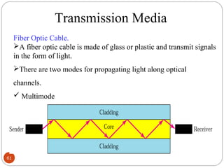
  • 61. 61 Transmission Media Fiber Optic Cable. A fiber optic cable is made of glass or plastic and transmit signals in the form of light. There are two modes for propagating light along optical channels.  Multimode  Single mode.
  • 62. LINE CODING&SCHEMES Line Coding is the process of converting binary data , a sequence of bits , to a digital signal
  • 63.  Unipolar encoding uses only one voltage level. LINE CODING&SCHEMES Polar encoding uses two voltage levels (positive and negative).Polar encoding uses two voltage levels (positive and negative).
  • 64. POLAR ENCODING&SCHEMES NRZ-LNRZ-L :The level of the signal is dependent upon the:The level of the signal is dependent upon the state of thestate of the bitbit NRZ-I:NRZ-I: The signal isThe signal is inverted if a 1 is encounteredinverted if a 1 is encountered..
  • 65. RZ encoding: POLAR ENCODING&SCHEMES Manchester encodingManchester encoding: the: the transition at the middle of the bittransition at the middle of the bit is used for both synchronization and bit representation.is used for both synchronization and bit representation.
  • 66. 66 Differential Manchester encoding:Differential Manchester encoding: TheThe transition at the middletransition at the middle of the bit is used only forof the bit is used only for synchronization.synchronization. The bit representation is defined by theThe bit representation is defined by the inversion or non-inversion or non- inversioninversion at theat the beginning of the bitbeginning of the bit.. POLAR ENCODING&SCHEMES
  • 67. BIPOLAR ENCODING Bipolar AMI encoding:Bipolar AMI encoding: Use three levels: positive, zero, andUse three levels: positive, zero, and negative.negative.
  • 68. 68 Modem Standards The term modem is a composite word that refers to the two functional entities that make up the device; a signal modulator and a signal demodulator. A modulator creates a bandpass analog signal from binary data. A demodulator recovers the binary data from the modulated signal.
  • 69. TELEPHONE MODEMS Traditional telephone lines can carry frequencies between 300 and 3300 HZ, giving them BW of 3000 Hz. The effective BW of a telephone line being used for data transmission is 2400 Hz,covering the range from 600 to 3000 Hz.
  • 70. Modem standards V-series standards published by the ITU-T. V.32: The V.32 calls for 32-QAM with a baud rate of 2400. Because only 4 bits of each pentabit represents data, the resulting speed is 4*2400=9600 V.32 bits: The V.32 bits modem support 14,400-bps transmission. The V.32 bits uses 128-QAM transmission. V.34 bits: The V.34 bits modem support 28,800-bps transmission with a 960-point constellation to a bit rate of 33,600 with a 1664-point constellation.
  • 71. Traditional modems In traditional modems data exchange is between two computers, A and B,through digital telephone network. After modulation by the modem, an analog signal reaches the telephone company Switching station. It is sampled and digitized to be passed through the digital network. The quantization noise introduced in the signal at the sampling point limits the data rate according to the capacity. This limit is 33.6 Kbps.
  • 73. 56K Modems Communication is via the Internet.  In Uploading, the analog signal must still be sampled at the switching station, which means the data rate in the uploading is limited to33.6 Kbps. There is no sampling in downloading. Data rate in downloading is 56Kbps
  • 75. RS 232 INTERFACE RS 232 is a standard interface by EIA and RS232C is the latest version of this interface. RS232 standard follows –ve logic.  Logic1 is represented by negative voltage. Logic0 is represented by +ve voltage. Level 1 varies from -3 to -15v and level 0 varies from 3 to15v
  • 76. 76 Data Link Layer design issues Services provided to the network layer=> Transfers the data from the network layer on the source to network layer on the destination The important services are, unacknowledged connectionless services Acknowledged connection service Acknowledged connection-oriented service
  • 77. 77 Framing=> separates a message from one source to a destination or from other messages to other destinations Fixed size framing Variable size framing o Character oriented protocol=> byte stuffing o Bit oriented protocol=>data as sequence of bits and interpreted by the upper layer as text, graphics, audio, etc.
  • 78. 78 Error Control Ensures proper sequencing and safe delivery of frames at destination An acknowledgement is send by destination node Positive acknowledgement=>frame is successfully delivered Negative acknowledgement=>frame not sent and the frame is to be retransmitted
  • 79. 79 Flow control =>the data flow is regulated Includes a feedback mechanism requesting transmitter to retransmit the data Damaged frames Lost frame Lost acknowledgement frames Most common retransmission technique=> ARQ(Automatic repeat request)
  • 80. 80 Error Detection & Correction Introduction Data can be corrupted during transmission For reliable communication, errors must be detected and corrected Error  Bits flow from one point to another  They subject to unpredictable changes because of interference is rightly called as an error
  • 81. 81 Error Detection Types of Errors  Single-Bit Errors only one bit in the data unit has changed
  • 82. 82 Error Detection  Burst Errors of length ‘n’: 2 or more bits in the data unit have changed
  • 83. 83 Error Detection Error Detection Sender transmits every data unit twice Receiver performs bit-by-bit comparison between that two versions of data Any mismatch would indicate an error, which needs error correction. Redundancy Shorter group of bits may be appended to the end of each unit
  • 84. 84 Error Detection Types of Redundancy Checks Parity Check  Simple Parity Check Two Dimensional Parity Check / Longitudinal Redundancy Check (LRC) Cyclic Redundancy Check (CRC) Check Sum
  • 85. 85 Parity check Parity A redundant bit called Parity Bit is added to every data unit Even Parity: total number of 1‘s in the data unit becomes even Odd Parity: total number of 1‘s in the data unit becomes odd
  • 86. 86 LONGTITUDINAL REDUNDANCY CHECK LRC - Performance Detects all burst errors up to length n (number of columns) If two bits in one data unit are damaged and two bits in exactly same positions in another data unit are also damaged. Now the checker will not detect an error
  • 88. 88 Cyclic redundancy check Powerful error detection scheme Rather than addition, binary division is used A sequence of redundant bits, called CRC or CRCremainder is appended to the data unit At the receiver side, the incoming data unit is divided by the same predetermined number. If there is no remainder, the data unit is accepted If there is a remainder, the receiver indicates that the data unit has been damaged during transmission
  • 90. 90 Error Correction Error Correction-Hamming Code Hamming Code uses the relationship between data and redundancy bits. For example: a 7-bit ASCII code requires 4 redundancy bits, which are placed in positions 1, 2, 4 and 8 i.e. x0,x1,x2,x3 and so on.
  • 91. 91 Error Correction –Hamming Code In the Hamming Code, each bit for one combination of data bits as below: r1: bits 1, 3, 5, 7, 9, 11 r2: bits 2, 3, 6, 7, 10, 11 r3: bits 4, 5, 6, 7 r4: bits 8, 9, 10, 11
  • 93. 93 Data Link Control  Flow Control  Error Control Flow Control: How much data sender can transmit before receiving the acknowledgement Error Control: Error Detection + Error Correction ARQ o Any time, an error is discovered in an exchange, specified frames are retransmitted
  • 94. 94 Flow and Error Control Mechanisms Flow and Error Control Mechanisms Stop and Wait ARQ  Go-Back ARQ Selective Repeat ARQ Stop and Wait ARQ  Simplest flow and error control mechanism  The sending device keeps a copy of the last frame transmitted until it receives an acknowledgement  Frames - alternately numbered as 0 and 1
  • 95. 95 Stop-and-Wait  Sender keeps a copy of the last frame until it receives an acknowledgement.  For identification, both data frames and acknowledgements (ACK) frames are numbered alternatively 0 and 1.  Sender has a control variable (S) that holds the number of the recently sent frame. (0 or 1)  Receiver has a control variable ® that holds the number of the next frame expected (0 or 1).  Sender starts a timer when it sends a frame. If an ACK is not received within a allocated time period, the sender assumes that the frame was lost or damaged and resends it  Receiver send only positive ACK if the frame is intact.  ACK number always defines the number of the next expected frame
  • 96. 96 Stop-and-Wait ARQ, lost ACK frame When a receiver receives a damaged frame, it discards it and keeps its value of R. After the timer at the sender expires, another copy of frame 1 is sent.
  • 97. 97 Stop-and-Wait, lost ACK frame • If the sender receives a damaged ACK, it discards it. • When the timer of the sender expires, the sender retransmits frame 1. • Receiver has already received frame 1 and expecting to receive frame 0 (R=0). Therefore it discards the second copy of frame 1.
  • 98. 98 Stop-and-Wait, delayed ACK frame • The ACK can be delayed at the receiver or due to some problem • It is received after the timer for frame 0 has expired. • Sender retransmitted a copy of frame 0. However, R =1 means receiver expects to see frame 1. Receiver discards the duplicate frame 0. • Sender receives 2 ACKs, it discards the second ACK.
  • 99. 99 Piggybacking • A method to combine a data frame with ACK. • Station A and B both have data to send. • Instead of sending separately, station A sends a data frame that includes an ACK. • Station B does the same thing. • Piggybacking saves bandwidth.
  • 100. 100 Disadvantage of Stop-and-Wait • In stop-and-wait, at any point in time, there is only one frame that is sent and waiting to be acknowledged. • This is not a good use of transmission medium. • To improve efficiency, multiple frames should be in transition while waiting for ACK. • Two protocol use the above concept, – Go-Back-N ARQ – Selective Repeat ARQ
  • 101. 101 Go-Back-N ARQ We can send up to W frames before worrying about ACKs. We keep a copy of these frames until the ACKs arrive. This procedure requires additional features to be added to Stop- and-Wait ARQ.
  • 102. 102 Sequence Numbers • Frames from a sender are numbered sequentially. • We need to set a limit since we need to include the sequence number of each frame in the header. • If the header of the frame allows m bits for sequence number, the sequence numbers range from 0 to 2 m – 1. for m = 3, sequence numbers are: 1, 2, 3, 4, 5, 6, 7. • We can repeat the sequence number. • Sequence numbers are: 0, 1, 2, 3, 4, 5, 6, 7, 0, 1, 2, 3, 4, 5, 6, 7, 0, 1, …
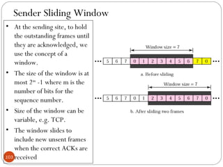
  • 103. 103 Sender Sliding Window • At the sending site, to hold the outstanding frames until they are acknowledged, we use the concept of a window. • The size of the window is at most 2m -1 where m is the number of bits for the sequence number. • Size of the window can be variable, e.g. TCP. • The window slides to include new unsent frames when the correct ACKs are received
  • 104. 104 Receiver Sliding Window • Size of the window at the receiving site is always 1 in this protocol. • Receiver is always looking for a specific frame to arrive in a specific order. • Any frame arriving out of order is discarded and needs to be resent. • Receiver window slides as shown in fig. Receiver is waiting for frame 0 in part a.
  • 105. 105 Control Variables • Sender has 3 variables: S, SF, and SL • S holds the sequence number of recently sent frame • SF holds the sequence number of the first frame • SL holds the sequence number of the last frame • Receiver only has the one variable, R, that holds the sequence number of the frame it expects to receive. If the seq. no. is the same as the value of R, the frame is accepted, otherwise rejected.
  • 106. 106 Go-Back-N ARQ, normal operation • The sender keeps track of the outstanding frames and updates the variables and windows as the ACKs arrive.
  • 107. 107 Go-Back-N ARQ, lost frame • Frame 2 is lost • When the receiver receives frame 3, it discards frame 3 as it is expecting frame 2 (according to window). • After the timer for frame 2 expires at the sender site, the sender sends frame 2 and 3. (go back to 2)
  • 108. 108 Go-Back-N ARQ, damaged/lost/delayed ACK • If an ACK is damaged/lost, we can have two situations: • If the next ACK arrives before the expiration of any timer, there is no need for retransmission of frames because ACKs are cumulative in this protocol. • If ACK1, ACK2, and ACk3 are lost, ACK4 covers them if it arrives before the timer expires. • If ACK4 arrives after time-out, the last frame and all the frames after that are resent. • Receiver never resends an ACK. • A delayed ACK also triggers the resending of frames
  • 109. 109 Go-Back-N ARQ, sender window size • Size of the sender window must be less than 2 m . Size of the receiver is always 1. If m = 2, window size = 2 m – 1 = 3. • Fig compares a window size of 3 and 4. Accepts as the 1st frame in the next cycle-an error
  • 110. 110 Selective Repeat ARQ, sender and receiver windows• Go-Back-N ARQ simplifies the process at the receiver site. Receiver only keeps track of only one variable, and there is no need to buffer out-of-order frames, they are simply discarded. • However, Go-Back-N ARQ protocol is inefficient for noisy link. It bandwidth inefficient and slows down the transmission. • In Selective Repeat ARQ, only the damaged frame is resent. More bandwidth efficient but more complex processing at receiver. • It defines a negative ACK (NAK) to report the sequence number of a damaged frame before the timer expires.
  • 111. 111 Selective Repeat ARQ, lost frame • Frames 0 and 1 are accepted when received because they are in the range specified by the receiver window. Same for frame 3. • Receiver sends a NAK2 to show that frame 2 has not been received and then sender resends only frame 2 and it is accepted as it is in the range of the window.
  • 112. 112 Selective Repeat ARQ, sender window size • Size of the sender and receiver windows must be at most one-half of 2 m . If m = 2, window size should be 2 m /2 = 2. Fig compares a window size of 2 with a window size of 3. Window size is 3 and all ACKs are lost, sender sends duplicate of frame 0, window of the receiver expect to receive frame 0 (part of the window), so accepts frame 0, as the 1st frame of the next cycle – an error.