


Cs intro-ca
- 1. Computer Systems • Lecturer: Szabolcs Mikulas • E-mail: [email protected] • URL: http://www.dcs.bbk.ac.uk/~szabolcs/compsys.html • Textbook: W. Stallings, Operating Systems: Internals and Design Principles, 6/E, Prentice Hall, 2006 • Recommended reading: W. Stallings, Computer Organization and Architecture 7th ed., Prentice Hall, 2008 A.S. Tanenbaum, Modern Operating Systems, 2nd or 3rd ed. Prentice Hall, 2001 or 2008
- 2. Operating Systems: Internals and Design Principles, 6/E William Stallings Chapter 1 Computer System Overview With additional inputs from Computer Organization and Architecture, Parts 1 and 2 Patricia Roy Manatee Community College, Venice, FL ©2008, Prentice Hall
- 3. Computer Structure - Top Level Peripherals Computer Central Processing Unit Computer Systems Interconnection Input Output Communication lines Main Memory
- 4. The Central Processing Unit - CPU CPU Computer Arithmetic and Logic Unit Registers I/O System Bus Memory CPU Internal CPU Interconnection Control Unit
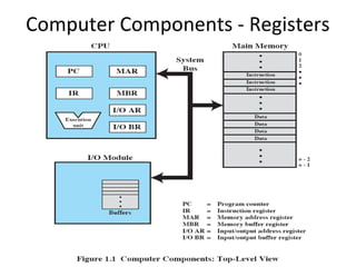
- 5. Computer Components - Registers
- 6. Control and Status Registers • Used by processor to control the operation of the processor • Used by privileged OS routines to control the execution of programs • Program counter (PC): Contains the address of the next instruction to be fetched • Instruction register (IR): Contains the instruction most recently fetched • Program status word (PSW): Contains status information
- 7. User-Visible Registers • May be referenced by machine language, available to all programs – application programs and system programs • Data • Address – Index: Adding an index to a base value to get the effective address – Segment pointer: When memory is divided into segments, memory is referenced by a segment and an offset inside the segment – Stack pointer: Points to top of stack
- 9. Fetch Cycle • Program Counter (PC) holds address of next instruction to be fetched • Processor fetches instruction from memory location pointed to by PC • Increment PC – Unless told otherwise • Instruction loaded into Instruction Register (IR) • Processor interprets instruction and performs required actions
- 10. Execute Cycle • Data transfer – Between CPU and main memory – Between CPU and I/O module • Data processing – Some arithmetic or logical operation on data • Control – Alteration of sequence of operations, e.g. jump • Combinations of the above
- 11. Characteristics of a Hypothetical Machine
- 12. Example of Program Execution
- 13. Interrupts • Interrupts the normal sequencing of the processor – suspends current activity and runs special code • Program generated: result of an instruction, e.g. division by 0, overflow, illegal machine instruction • Hardware generated: timer, I/O (when finished or error), other errors (e.g. parity check)
- 14. Program Flow of Control
- 15. Program Flow of Control
- 16. Interrupt Stage • Processor checks for interrupts • If interrupt occurred – Suspend execution of program – Execute interrupt-handler routine – Afterwards control may be returned to suspended program
- 17. Transfer of Control via Interrupts
- 18. Instruction Cycle with Interrupts
- 20. Multiple Interrupts 1 Disable interrupts – Processor will ignore further interrupts whilst processing one interrupt – Interrupts remain pending and are checked after first interrupt has been processed – Interrupts handled in sequence as they occur 2 Define priorities – Low priority interrupts can be interrupted by higher priority interrupts – When higher priority interrupt has been processed, processor returns to previous interrupt
- 23. Time Sequence of Multiple Interrupts
- 24. Connecting • All the units must be connected • Different type of connection for different type of unit – Memory – Input/Output – CPU
- 25. Computer Modules
- 26. Memory Connection • Receives and sends data • Receives addresses (of locations) • Receives control signals – Read – Write – Timing
- 27. Input/Output Connection(1) • Similar to memory from computer’s viewpoint • Output – Receive data from computer – Send data to peripheral • Input – Receive data from peripheral – Send data to computer
- 28. Input/Output Connection(2) • Receive control signals from computer • Send control signals to peripherals – e.g. spin disk • Receive addresses from computer – e.g. port number to identify peripheral • Send interrupt signals (control)
- 29. CPU Connection • • • • Reads instruction and data Writes out data (after processing) Sends control signals to other units Receives (& acts on) interrupts
- 30. Physical Realization of Bus Architecture
- 32. Data Bus • Carries data – Remember that there is no difference between “data” and “instruction” at this level • Width (number of lines) is a key determinant of performance, since this determines how many bits can be transferred in one go (cycle) – 32 to hundreds of bits
- 33. Address bus • Identify the source or destination of data • e.g. CPU needs to read an instruction (data) from a given location in memory • Bus width determines maximum memory capacity of system – e.g. 8080 has 16 bit address bus giving 64k address space
- 34. Control Bus • • • • Memory or I/O read/write signals Interrupt request/acknowledgment Clock signals Bus request/grant signals
- 35. Traditional (ISA) (with cache)
- 36. Memory Hierarchy • Faster access time, greater cost per bit • Greater capacity, smaller cost per bit • Greater capacity, slower access speed
- 38. Going Down the Hierarchy • • • • Decreasing cost per bit Increasing capacity Increasing access time Decreasing frequency of access to the memory by the processor (optimally - requires good design)
- 39. Performance Balance • Processor speed increased • Memory capacity increased • Memory speed lags behind processor speed
- 40. Logic and Memory Performance Gap
- 41. Cache Memory • Processor speed faster than memory access speed • Exploit the principle of locality of reference: During the course of the execution of a program, memory references tend to cluster, e.g. loops
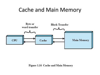
- 42. Cache and Main Memory
- 43. Cache Principles • • • • Contains copy of a portion of main memory Processor first checks cache If not found, block of memory read into cache Because of locality of reference, likely future memory references are in that block • Modern systems have several caches (instruction, data) on different levels (L1 on chip, L2, etc.)
- 46. Size • Cache size – Small caches have significant impact on performance • Block size – The unit of data exchanged between cache and main memory – Larger block size results in more hits until probability of using newly fetched data becomes less than the probability of reusing data that have to be moved out of cache
- 47. (Re)placement • Mapping function – Determines which cache location the block will occupy • Replacement algorithm – Chooses which block to replace – Least-recently-used (LRU) algorithm
- 48. Write policy • Dictates when the memory write operation takes place – Write through: occurs every time the block is updated – Write back: occurs when the block is replaced • Minimize write operations • Leave main memory in an obsolete state
- 49. Dynamic RAM • • • • • • • • • • Bits stored as charge in capacitors Charges leak Need refreshing even when powered Simpler construction Smaller per bit Less expensive Need refresh circuits Slower Main memory Essentially analogue – Level of charge determines value
- 50. Static RAM • • • • • • • • • • Bits stored as on/off switches No charges to leak No refreshing needed when powered More complex construction Larger per bit More expensive Does not need refresh circuits Faster Cache Digital – Uses flip-flops
- 51. I/O Devices • Programs with intensive I/O demands • Large data throughput demands • Processors can handle this, but memory is limited and slow • Problem moving data • Solutions: – Caching – Buffering – Higher-speed interconnection buses – More elaborate bus structures – Multiple-processor configurations
- 52. Typical I/O Device Data Rates
- 53. Hard disk
- 54. Speed • Seek time – Moving head above the correct track • (Rotational) latency – Waiting for the correct sector to rotate under head • Access time = Seek + Latency • Transfer rate
- 55. Input/Output Problems • Wide variety of peripherals – Delivering different amounts of data – At different speeds – In different formats • All slower than CPU and RAM • Need I/O modules
- 56. I/O Steps • • • • • • CPU checks I/O module device status I/O module returns status If ready, CPU requests data transfer I/O module gets data from device I/O module transfers data to CPU Variations for output, DMA, etc.
- 57. I/O Mapping • Memory mapped I/O – Devices and memory share an address space – I/O looks just like memory read/write – No special commands for I/O • Large selection of memory access commands available • Isolated I/O – Separate address spaces – Need I/O or memory select lines – Special commands for I/O • Limited set
- 58. Input Output Techniques • Programmed • Interrupt driven • Direct Memory Access (DMA)
- 59. Programmed I/O (1) • CPU has direct control over I/O – Sensing status – Read/write commands – Transferring data • CPU waits for I/O module to complete operation • Wastes CPU time
- 60. Programmed I/O (2) • • • • • • • CPU requests I/O operation I/O module performs operation I/O module sets status bits CPU checks status bits periodically I/O module does not inform CPU directly I/O module does not interrupt CPU CPU may wait or come back later
- 61. Programmed I/O (3) • I/O module performs the action • Sets the appropriate bits in the I/O status register • CPU checks status bits periodically • No interrupts occur • Processor checks status until operation is complete
- 62. Interrupt Driven I/O • Overcomes CPU waiting • No repeated CPU checking of device • I/O module interrupts when ready
- 63. Interrupt Driven I/O (2) • CPU issues read command • I/O module gets data from peripheral while CPU does other work • I/O module interrupts CPU • CPU requests data • I/O module transfers data
- 64. Interrupt-Driven I/O (3) • Processor is interrupted when I/O module ready to exchange data • Processor saves context of program executing and begins executing interrupt-handler
- 66. Direct Memory Access • Interrupt driven and programmed I/O require active CPU intervention – Transfer rate is limited – CPU is tied up • DMA, an additional module (hardware) on bus • DMA controller takes over from CPU for I/O
- 67. Typical DMA Module Diagram
- 68. DMA Operation • CPU tells DMA controller:– Read/Write – Device address – Starting address of memory block for data – Amount of data to be transferred • CPU carries on with other work • DMA controller deals with transfer • DMA controller sends interrupt when finished
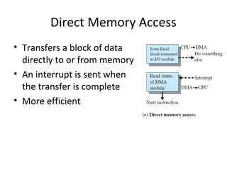
- 69. Direct Memory Access • Transfers a block of data directly to or from memory • An interrupt is sent when the transfer is complete • More efficient
- 70. DMA Transfer - Cycle Stealing • DMA controller takes over bus for a cycle • Transfer of one word of data • Not an interrupt – CPU does not switch context • CPU suspended just before it accesses bus – i.e. before an operand or data fetch or a data write • Slows down CPU but not as much as CPU doing transfer
- 71. DMA Configurations (1) • Single Bus, Detached DMA controller • Each transfer uses bus twice – I/O to DMA then DMA to memory • CPU is suspended twice
- 72. DMA Configurations (2) • Single Bus, Integrated DMA controller • Controller may support >1 device • Each transfer uses bus once – DMA to memory • CPU is suspended once
- 73. Improvements in Chip Organization and Architecture • Increase hardware speed of processor – Fundamentally due to shrinking logic gate size • More gates, packed more tightly, increasing clock rate • Propagation time for signals reduced • Increase size and speed of caches – Dedicating part of processor chip • Cache access times drop significantly • Change processor organization and architecture – Increase effective speed of execution – Parallelism
- 74. Problems with Clock Speed and Logic Density • Power – Power density increases with density of logic and clock speed – Dissipating heat • RC delay – Speed at which electrons flow limited by resistance and capacitance of metal wires connecting them – Delay increases as RC product increases – Wire interconnects thinner, increasing resistance – Wires closer together, increasing capacitance • Memory latency – Memory speeds lag processor speeds • Solution: More emphasis on organizational and architectural approaches
- 75. Increased Cache Capacity • Typically two or three levels of cache between processor and main memory • Chip density increased – More cache memory on chip - faster cache access • Pentium chip devoted about 10% of chip area to cache • Pentium 4 devotes about 50%
- 76. More Complex Execution Logic • Enable parallel execution of instructions • Pipeline works like assembly line – Different stages of execution of different instructions at same time along pipeline • Superscalar allows multiple pipelines within single processor – Instructions that do not depend on one another can be executed in parallel
- 77. New Approach – Multiple Cores • Multiple processors on single chip – Large shared cache • Within a processor, increase in performance proportional to square root of increase in complexity • If software can use multiple processors, doubling number of processors almost doubles performance • So, use two simpler processors on the chip rather than one more complex processor • Example: IBM POWER4 – Two cores based on PowerPC