SlideShare a Scribd company logo
CST-20363-Intro-to-CS
“Software suppliers are trying to make their software packages more ‘user-
friendly’… Their best approach so far has been to take all the old
brochures and stamp the words ‘user-friendly’ on the cover.”
-Bill Gates (Microsoft Founder)
Chapter 4 “Computer Logic Design”
“It is evidently equally foolish to accept probable reasoning
from a mathematician and to demand from a rhetorician
demonstrative proofs”.
-Aristotle
A Basic Overview of Computer Architecture
Early computing technology
Early computing could be traced back to the abacus. When
was the abacus in use?
In the mid 1600’s Blaise Pascal designed and implemented a
mechanical calculator.
Note: Today we use voltage level to represent a logical TRUE and
FALSE. There is no reason that the physical position of a
mechanical component cannot do the same thing.
3
Around 2700 B.C.
A little more modern
Charles Babbage 1792-1871
 The Difference Engine
 The Difference Engine 2
Basically, a programmable calculator
Calculated artillery tables
 The Analytic Engine (advanced machine)
Used punch cards for input
A precursor to the modern computer
4
Boole 1815-1864
 Boolean Algebra
 English mathematician
 helped establish modern
symbolic logic
 Boolean algebra, is basic to
the design of digital
computer circuits.
CST 20363 Session 4 Computer Logic Design
Still, a little more modern
The von Neumann architecture –
1940s and 50s
• A stored-program computer
that uses a central processing
unit and a single separate
storage structure that hold both
instructions and data.
24
Basic operation of architecture
 Instructions are executed in sequence
 First step during execution
 MEM(PC)  IR
 Send contents of PC (Program counter) to
memory
 Memory responds with the contents at that
address placing it on the data bus.
 Increment the PC (PC+1->PC)
 The values on the data bus are loaded into the
instruction register
25
Decode Instruction and execute
 Say the instruction was a load
immediate
 This means that the next word in the
instruction stream is the data that we
want loaded into the accumulator
 Operation is now
MEM(PC) Accum
Also increment the PC
26
I/O system
Instr. Set Proc.
Compiler
Operating
System
Application
Digital Design
Circuit Design
Instruction Set
Architecture
Firmware
Datapath & Control
Layout
Software
Hardware
Software/Hardware
Boundary
High-Level Language Programs
Assembly Language
Programs
Microprogram
Register Transfer
Notation (RTN)
Logic Diagrams
Circuit Diagrams
Machine Language
Program
Hierarchy of Computer Architecture
computer system components
• A computer system is composed of many parts, both hardware
and software.
• At the heart of the computer is the processor, the hardware
that executes the computer programs.
• The computer also has memory, often several different
types in one system.
• The memory is used to store programs while the
processor is running them, as well as store the data
that the programs are manipulating.
• The computer also has devices for storing data, or
exchanging data with the outside world.
• These may allow the input of text via a keyboard, the display of
information on a screen, or the movement of programs and
data to or from a disk drive.
Basic System Architecture
The processor alone is
incapable of successfully
performing any tasks. It requires
memory (for program and data
storage), support logic, and at
least one I/O device
(“input/output device”) used to
transfer data between the
computer and the outside
world.
Buses
A bus is a physical group
of signal lines that have a
related function.
Buses allow for the transfer
of electrical signals
between different parts of
the computer system and
thereby transfer
information from one
device to another.
For example, the data bus
The majority of microprocessors
available today (with some
exceptions) use the three-bus system
architecture The three buses are
the address bus , the data bus, and
the control bus .
Memory
Memory is used to hold data and
software for the processor. There is
a variety of memory types, and
often a mix is used within a single
system.
Memory chips can be organized in two ways, either
in word-organized or bit-organized schemes. In the
word-organized scheme, complete nybbles, bytes, or
words are stored within a single component,
Eight bit-organized 8×1 devices and
one word-organized 8×8 device
RAM
The entire memory space – 16 bit address (65,536)
• RAM is in the first 256 locations - $0000 to $00FF
• These locations are available using direct addressing mode.
• Direct addressing mode assumes the upper byte of the address is $00
• Saves space in program memory – only 8 bits for address and a 1 word instruction versus 2
• Saves a cycle of execution as only one fetch to load the instruction
• By using the INIT register, 4-bits, RAM can be moved to the start of any 4K partition
within the memory space as the INIT register specifies the upper 4-bits when direct
addressing modes is used. INIT starts with 0000
RAM
The contents in RAM are lost if power is lost.
The design is fully static RAM so the data is not lost if the clocks are halted.
• In DRAM – Dynamic RAM – clocks are needed to keep the data refreshed
as the contents are not static. The charge that determines the value of
that bit will bleed off if not refreshed.
What is the difference – RAM and ROM
RAM = Random Access Memory
As the name implies any location of the memory can be
accessed in any order, i.e., randomly.
Given an address, the data is stored at that address, or
the data at that address is retrieved, depending on the
mode of access (read or write).
RAM is the memory where data is stored.
What is the difference – RAM and ROM
ROM = Read Only Memory
• Memory that can only be read.
This is memory that can only be read.
There are different types
One time programmable, UV erasable, EEPROM –
electrically erasable
ROM will maintain the contents even when power is off.
Embedded Computer Architecture
What a computer is used for,
what tasks it must perform,
and how it interacts with
humans and other systems
determine the functionality
of the machine and,
therefore, its architecture,
memory, and I/O.
logic design
What is logic design?
What is design?
• Given a specification of a problem, come up with a way of solving it
choosing appropriately from a collection of available components
• While meeting some criteria for size, cost, power, beauty, elegance,
etc.
What is logic design?
• Determining the collection of digital logic components to perform a specified control
and/or data manipulation and/or communication function and the interconnections
between them
• Which logic components to choose? – there are many implementation
technologies (e.g., off-the-shelf fixed-function components, programmable devices,
transistors on a chip, etc.)
• The design may need to be optimized and/or transformed to meet design constraints
CS 150 - Fall 2000 - Introduction - 40
sense
sense
drive
AND
What is digital hardware?
Collection of devices that sense and/or
control wires carrying a digital value (i.e., a
physical quantity interpreted as a “0” or “1”)
• e.g., digital logic where voltage < 0.8v is
a “0” and > 2.0v is a “1”
• e.g., pair of transmission wires where a
“0” or “1” is distinguished by which wire
has a higher voltage (differential)
• e.g., orientation of magnetization
signifies a “0” or a “1”
Primitive digital hardware devices
Logic computation devices (sense
and drive)
two wires both “1” - make
another be “1” (AND)
at least one of two wires “1” -
make another be “1” (OR)
a wire “1” - then make
another be “0” (NOT)
Memory devices (store)
store a value
recall a value previously
stored
What is happening now in digital design?
Big change in how industry does hardware
design
• Larger and larger designs
• Shorter and shorter time to market
• Cheaper and cheaper products
Scale
• Pervasive use of computer-aided design
tools over hand methods
• Multiple levels of design representation
Time
• Emphasis on abstract design
representations
• Programmable rather than fixed
function components
• Automatic synthesis techniques
• Importance of sound design
methodologies
Cost
• Higher levels of integration
• Use of simulation to debug
designs
close switch (if A is “1” or asserted)
and turn on light bulb (Z)
A Z
open switch (if A is “0” or unasserted)
and turn off light bulb (Z)
Switches: basic element of physical
implementations
Implementing a simple circuit (arrow shows action if wire changes to “1”):
Z  A
A
Z
AND
OR
Z  A and B
Z  A or B
A B
A
B
Switches (cont’d)
Compose switches into more complex ones (Boolean functions):
Introduction to Digital Systems
Analog devices and systems process time-varying signals that can take on any value across a
continuous range.
Digital systems use digital circuits that process digital signals which can take on one of two
values, we call:
0 and 1 (digits of the binary number system)
or LOW and HIGH
or FALSE and TRUE
Digital computers represent the most common digital systems.
Once-analog Systems that use digital systems today:
• Audio recording (CDs, DAT, mp3)
• Phone system switching
• Automobile engine control
• Movie effects
• Still and video cameras….
High
Low
Digital
circuit
inputs outputs
: :
Analog Signal
Digital Signal
Program Design
Program Design
General Overview
• “The design of an embedded microcontroller system requires an
integrated use of hardware and software.”
• Hardware and software provide a natural division of the view of the
system. Embedded systems require well designed interaction
between these two divisions.
• The software design needs to follow established methodologies.
46
Software Design Methodology
• The software of the system is typically called a Software Program.
• A software program is software compiled and assembled into
executable code for the target machine.
• Window OS is a program designed as the operating system for
general purpose PCs and will run on hardware structured to
support that OS.
47
Top-down design methodology
• A popular design methodology for software is
Top-Down design and Bottom-up coding.
• It starts with a specification of the system at the
top level.
• This top-level is then broken down into major tasks
and subtasks.
• Each major task (and subtask) is broken down into
smaller subtasks as appropriate.
Graphical illustration
of the Top-down
design methodology.
The number of levels
continues until the
subtask is one that can
be directly coded.
Benefits of the top-down method
• Each subtask is independent of other subtasks, allowing the programmer to design,
write and test each module independently.
• Errors can be detected and corrected in a logical manner.
• Mentally, the programmer only has to grasp one subtask at a time.
• A team of programmer can be used to accomplish the project faster.
• Program modules can be used in future applications. For example, your program
needs to use a linked list data structure. Most likely the routines to manage and
manipulate a linked list are available.
Statement of the problem
Where it all starts.
The highest level of abstraction
• The statement of the problem to be solved
Requires full analysis of the problem to be addressed and the system being designed to address it.
10/8/2021
ECE265
50
An example of the methodology
Where it all starts.
The highest level of abstraction
• The statement of the problem to be solved
Requires full analysis of the problem to be addressed and
the system being designed to address it.
Assembler language programming
• A good practice is never to program in
assembler language directly.
• Start with the specification of the module to be coded.
• Code it in a Pseudo Design Language or PDL
• PDL is much like any high-level programming language.
Assembler Language
• Assembler Language is specific to the machine (processor architecture).
• Each processor version may have instructions that other versions do not have.
• Assembler language has a 1-to-1 relationship with the machine language, i.e., executable
code of the processor.
• One assembler language statement
• =
• one executable instruction.
53
Assembler language
Usually, written line by line where each line is 80 character long.
Within the 80-character line there are fields. Field position can be fixed. For example:
• The first 10 characters are a label
• The next field is for the operand or assembler directive
• This is followed by the operand field
• The last filed is for comments
Boolean Logic
& Logic Gates
& Boolean Algebra
Boolean algebra is a mathematical system for the manipulation of variables that
can have one of two values.
• In formal logic, these values are “true” and “false.”
• In digital systems, these values are “on” and “off,” 1 and 0, or “high” and “low.”
Boolean expressions are created by performing operations on Boolean
variables.
• Common Boolean operators include AND, OR, and NOT.
Introduction
Introduction cont.
All switching devices we will use are two-state devices, so we will emphasize the case in which
all variables assume only one of two values.
Boolean variable X or Y will be used to represent input or output of switching circuit.
Symbols “0” and “1” represent the two values any variable can take on. These represent states
in a logic circuit, and do not have numeric value.
Logic gate: 0 usually represents range of low voltages and 1 represents range of high voltages
Switch circuit: 0 represents open switch and 1 represents closed
0 and 1 can be used to represent the two states in any binary valued system.
Boolean Login & Login Gates
Boolean Algebra
Rules that govern constants and variables that can take on 2 values
• True/false; on/off; yes/no; 0/1
Boolean logic
• Rules for handling Boolean constants and variables
• 3 fundamental operations:
AND, OR and NOT
• Truth Table: specifies results for all possible input combinations
 A Boolean operator can be completely
described using a truth table.
 The truth table for the Boolean operators
AND and OR are shown at the right.
 The AND operator is also known as a
Boolean product. The OR operator is the
Boolean sum.
Boolean Algebra
A Boolean function has:
• At least one Boolean variable,
• At least one Boolean operator, and
• At least one input from the set {0,1}.
It produces an output that is also a member of the set {0,1}.
Now you know
why the binary
numbering
system is so
handy in digital
systems.
Boolean Algebra
We have looked at Boolean functions in abstract terms.
In the next section, we’ll see that Boolean functions are implemented in digital computer
circuits called gates.
A gate is an electronic device that produces a result based on two or more input values.
• In reality, gates consist of one to six transistors, but digital designers think of them as a
single unit.
• Integrated circuits contain collections of gates suited to a particular purpose.
Boolean LOGIC GATES
The truth table for the Boolean
NOT operator is shown at the right.
The NOT operation is most often
designated by an overbar.
It is sometimes indicated by a
prime mark ( ‘ ) or an “elbow” ().
Boolean LOGIC GATES
Boolean Login & Login Gates
CST 20363 Session 4 Computer Logic Design
Boolean LOGIC GATES
Boolean Algebra
CST 20363 Session 4 Computer Logic Design
EXCLUSIVE OR
a
b
a.b
a
b
a+b
a a'
a
b
(a+b)'
a
b
(a.b)'
a
b
a  b
a
b
a.b
&
a
b
a+b
+
AND
a a'
1
a
b
(a.b)'
&
a
b
(a+b)'
1
a
b
a  b
=1
OR
NOT
NAND
NOR
Symbol set 1 Symbol set 2
(ANSI/IEEE Standard 91-1984)
Boolean LOGIC GATES
Boolean
LOGIC
GATES
Boolean Algebra
Basic Operations
• Also known as Switching Algebra
› Invented by mathematician George Boole in 1849
› Used by Claude Shannon at Bell Labs in 1938
• T
o describe digital circuits built from relays
• Digital circuit design is based on
› Boolean Algebra
• Attributes
• Postulates
• Theorems
› These allow minimization and manipulation of
logic gates for optimizing digital circuits
Basic Operations
• Binary
› A1a: X=0 ifX=1
› A1b: X=1 ifX=0
• Complement
› aka invert,NOT
› A2a: if X=0, X’=1
X Y X•Y
0 0 0
0 1 0
1 0 0
1 1 1
• AND operation
› A3a:0•0=0
› A4a:1•1=1
› A5a: 0•1=1•0=0
- The dot • means AND
- Other symbol forAND:
X•Y=XY(no symbol)
› A2b: if X=1, X’=0
- The tick mark ’ means
complement,invert,
or NOT
- Other symbolfor
complement: X’= X
› A3b:1+1=1
› A4b:0+0=0
› A5b: 1+0=0+1=1
- The plus + means OR
X Y X+Y
0 0 0
0 1 1
1 0 1
1 1 1
X X’
0 1
1 0
• OR Operation
74
BOOLEAN ALGEBRA ATTRIBUTES
• Variable: Variables are the different symbols in a Boolean expression
• Literal: Each occurrence of a variable or its complement is called a literal
• Term:A term is the expression formed by literals and operations at one
level
– A, B, C are three variables
– Eight Literals
– Expression has five terms including four AND terms and the OR term
that combines the first-level AND terms.
75
Basic Operations Series Switching Circuits/ AND :
76
Series:
A) Truth table
B) Logic gate diagram
C) Switch circuit diagram
A)
C)
B)
• The operation defined by the table is called AND.
• It is written algebraically as C=A·B.
• We will usually write AB or A·B.
• The AND operation is also referred to as logical (or Boolean) multiplication.
Basic Operations Parallel Switching Circuits/ OR
Series:
A) Truth table
B) Logic gate diagram
C) Switch circuit diagram
If switches A and B are connected in
parallel, there is a closed circuit if either
A or B, or both, are closed and an open
circuit only if A and B are both open.
A)
B)
C)
The operation defined by the table is called OR. It is written algebraically as C=A+B
The OR operation is also referred to as logical (or Boolean) addition.
Basic Operations Parallel Switching Circuits/ NOT
Series:
A) Truth table
B) Logic gate diagram
C) Switch circuit diagram
A simple 2-input logic NOT gate can be constructed using
a RTL Resistor-transistor switches as shown below with
the input connected directly to the transistor base.
The transistor must be saturated “ON” for an inverted
output “OFF” at Q.
A)
B)
C)
The standard NOT gate is given a symbol whose shape is of a triangle pointing to the right with a circle at its
end. This circle is known as an “inversion bubble” and is used in NOT, NAND and NOR symbols at their
output to represent the logical operation of the NOT function.
x ¬x
0 1
1 0
x x'
Examples Boolean Logic Circuits
When a Boolean expression is provided, we can easily draw the
logic circuit.
Examples:
F1 = xyz'
(note the use of a 3-input AND gate)
x
y
z
F1
z'
Analyzing Logic Circuits
When a logic circuit is provided, we can analyse the circuit to
obtain the logic expression.
Example: What is the Boolean expression of F4?
A'B' A'B'+C (A'B'+C)'
A'
B'
C
F4
F4 = (A'B'+C)'
Ad

More Related Content

What's hot (20)

Superscalar & superpipeline processor
Superscalar & superpipeline processorSuperscalar & superpipeline processor
Superscalar & superpipeline processor
Muhammad Ishaq
 
Role of system analyst
Role of system analystRole of system analyst
Role of system analyst
ShaileshModi9
 
USB 3.0
USB 3.0USB 3.0
USB 3.0
Ali Habeeb
 
Computer performance
Computer performanceComputer performance
Computer performance
Amit Kumar Rathi
 
Computer Organization
Computer OrganizationComputer Organization
Computer Organization
Selvaraj Seerangan
 
Evolution and History of Programming Languages - Software/Hardware/System
Evolution and History of Programming Languages - Software/Hardware/SystemEvolution and History of Programming Languages - Software/Hardware/System
Evolution and History of Programming Languages - Software/Hardware/System
Amity University | FMS - DU | IMT | Stratford University | KKMI International Institute | AIMA | DTU
 
Memory management in operating system | Paging | Virtual memory
Memory management in operating system | Paging | Virtual memoryMemory management in operating system | Paging | Virtual memory
Memory management in operating system | Paging | Virtual memory
Shivam Mitra
 
Unit 4 Real Time Operating System
Unit 4 Real Time Operating SystemUnit 4 Real Time Operating System
Unit 4 Real Time Operating System
Dr. Pankaj Zope
 
Instruction Set Architecture
Instruction Set ArchitectureInstruction Set Architecture
Instruction Set Architecture
Dilum Bandara
 
parallel processing
parallel processingparallel processing
parallel processing
Sudarshan Mondal
 
Incremental Model
Incremental ModelIncremental Model
Incremental Model
Mobeen Mustafa
 
Parallel processing
Parallel processingParallel processing
Parallel processing
Praveen Kumar
 
Computer architecture
Computer architectureComputer architecture
Computer architecture
Zuhaib Zaroon
 
Introduction to Software Engineering
Introduction to Software EngineeringIntroduction to Software Engineering
Introduction to Software Engineering
AnwarrChaudary
 
Session 8 assertion_based_verification_and_interfaces
Session 8 assertion_based_verification_and_interfacesSession 8 assertion_based_verification_and_interfaces
Session 8 assertion_based_verification_and_interfaces
Nirav Desai
 
Problem Solving Techniques
Problem Solving TechniquesProblem Solving Techniques
Problem Solving Techniques
Ashesh R
 
Instruction pipeline: Computer Architecture
Instruction pipeline: Computer ArchitectureInstruction pipeline: Computer Architecture
Instruction pipeline: Computer Architecture
InteX Research Lab
 
Rtos Concepts
Rtos ConceptsRtos Concepts
Rtos Concepts
Sundaresan Sundar
 
Evolution of Programming Languages Over the Years
Evolution of Programming Languages Over the YearsEvolution of Programming Languages Over the Years
Evolution of Programming Languages Over the Years
designs.codes
 
contiguous memory allocation.pptx
contiguous memory allocation.pptxcontiguous memory allocation.pptx
contiguous memory allocation.pptx
Rajapriya82
 
Superscalar & superpipeline processor
Superscalar & superpipeline processorSuperscalar & superpipeline processor
Superscalar & superpipeline processor
Muhammad Ishaq
 
Role of system analyst
Role of system analystRole of system analyst
Role of system analyst
ShaileshModi9
 
Memory management in operating system | Paging | Virtual memory
Memory management in operating system | Paging | Virtual memoryMemory management in operating system | Paging | Virtual memory
Memory management in operating system | Paging | Virtual memory
Shivam Mitra
 
Unit 4 Real Time Operating System
Unit 4 Real Time Operating SystemUnit 4 Real Time Operating System
Unit 4 Real Time Operating System
Dr. Pankaj Zope
 
Instruction Set Architecture
Instruction Set ArchitectureInstruction Set Architecture
Instruction Set Architecture
Dilum Bandara
 
Computer architecture
Computer architectureComputer architecture
Computer architecture
Zuhaib Zaroon
 
Introduction to Software Engineering
Introduction to Software EngineeringIntroduction to Software Engineering
Introduction to Software Engineering
AnwarrChaudary
 
Session 8 assertion_based_verification_and_interfaces
Session 8 assertion_based_verification_and_interfacesSession 8 assertion_based_verification_and_interfaces
Session 8 assertion_based_verification_and_interfaces
Nirav Desai
 
Problem Solving Techniques
Problem Solving TechniquesProblem Solving Techniques
Problem Solving Techniques
Ashesh R
 
Instruction pipeline: Computer Architecture
Instruction pipeline: Computer ArchitectureInstruction pipeline: Computer Architecture
Instruction pipeline: Computer Architecture
InteX Research Lab
 
Evolution of Programming Languages Over the Years
Evolution of Programming Languages Over the YearsEvolution of Programming Languages Over the Years
Evolution of Programming Languages Over the Years
designs.codes
 
contiguous memory allocation.pptx
contiguous memory allocation.pptxcontiguous memory allocation.pptx
contiguous memory allocation.pptx
Rajapriya82
 

Similar to CST 20363 Session 4 Computer Logic Design (20)

An Introduction To Python - Understanding Computers
An Introduction To Python - Understanding ComputersAn Introduction To Python - Understanding Computers
An Introduction To Python - Understanding Computers
Blue Elephant Consulting
 
Microprocessor
MicroprocessorMicroprocessor
Microprocessor
Embeddedbvp
 
digital logic circuits, digital component
digital logic circuits, digital componentdigital logic circuits, digital component
digital logic circuits, digital component
Rai University
 
Unit 1 Presentation and notes with according to syllabus
Unit 1 Presentation and notes with according to syllabusUnit 1 Presentation and notes with according to syllabus
Unit 1 Presentation and notes with according to syllabus
NiteshNema4
 
Introduction to computer systems. Architecture of computer systems.
Introduction to computer systems. Architecture of computer systems.Introduction to computer systems. Architecture of computer systems.
Introduction to computer systems. Architecture of computer systems.
TazhikDukenov
 
Bca 2nd sem-u-1.2 digital logic circuits, digital component
Bca 2nd sem-u-1.2 digital logic circuits, digital componentBca 2nd sem-u-1.2 digital logic circuits, digital component
Bca 2nd sem-u-1.2 digital logic circuits, digital component
Rai University
 
Coa module1
Coa module1Coa module1
Coa module1
cs19club
 
coa-module1-170527034116.pdf
coa-module1-170527034116.pdfcoa-module1-170527034116.pdf
coa-module1-170527034116.pdf
SnehithaKurimelli
 
B.sc cs-ii -u-1.2 digital logic circuits, digital component
B.sc cs-ii -u-1.2 digital logic circuits, digital componentB.sc cs-ii -u-1.2 digital logic circuits, digital component
B.sc cs-ii -u-1.2 digital logic circuits, digital component
Rai University
 
hgfhfghfg gvhhhgjfg gtfhngfjhfk jkfgfgjfgj
hgfhfghfg gvhhhgjfg gtfhngfjhfk jkfgfgjfgjhgfhfghfg gvhhhgjfg gtfhngfjhfk jkfgfgjfgj
hgfhfghfg gvhhhgjfg gtfhngfjhfk jkfgfgjfgj
mindzyp
 
BCS 100: Introduction to Computer Science Lesson 3
BCS 100: Introduction to Computer Science Lesson 3BCS 100: Introduction to Computer Science Lesson 3
BCS 100: Introduction to Computer Science Lesson 3
Ndubi Amos
 
CO lec.1.pptx lec.1lec.1lec.1lec.1lec.1lec.1lec.1
CO lec.1.pptx lec.1lec.1lec.1lec.1lec.1lec.1lec.1CO lec.1.pptx lec.1lec.1lec.1lec.1lec.1lec.1lec.1
CO lec.1.pptx lec.1lec.1lec.1lec.1lec.1lec.1lec.1
aliashraf9689
 
Module 1 unit 3
Module 1  unit 3Module 1  unit 3
Module 1 unit 3
Ayebazibwe Kenneth
 
abc
abcabc
abc
Dinesh Dinesh
 
PC for Managers
PC for ManagersPC for Managers
PC for Managers
Hazel Anne Quirao
 
E 1-00powerpointpresentationupdate-090901115018-phpapp01
E 1-00powerpointpresentationupdate-090901115018-phpapp01E 1-00powerpointpresentationupdate-090901115018-phpapp01
E 1-00powerpointpresentationupdate-090901115018-phpapp01
12richa
 
Mechatronics ME8791
Mechatronics ME8791 Mechatronics ME8791
Mechatronics ME8791
DrPETERPRAKASH
 
Introduction to embedded System.pptx
Introduction to embedded System.pptxIntroduction to embedded System.pptx
Introduction to embedded System.pptx
Pratik Gohel
 
chapter 1 of computers organization .pdf
chapter 1 of computers organization .pdfchapter 1 of computers organization .pdf
chapter 1 of computers organization .pdf
nosybaahmed2
 
Computer Architecture and Organization ppt
Computer Architecture and Organization pptComputer Architecture and Organization ppt
Computer Architecture and Organization ppt
JayasimhaThummala1
 
An Introduction To Python - Understanding Computers
An Introduction To Python - Understanding ComputersAn Introduction To Python - Understanding Computers
An Introduction To Python - Understanding Computers
Blue Elephant Consulting
 
digital logic circuits, digital component
digital logic circuits, digital componentdigital logic circuits, digital component
digital logic circuits, digital component
Rai University
 
Unit 1 Presentation and notes with according to syllabus
Unit 1 Presentation and notes with according to syllabusUnit 1 Presentation and notes with according to syllabus
Unit 1 Presentation and notes with according to syllabus
NiteshNema4
 
Introduction to computer systems. Architecture of computer systems.
Introduction to computer systems. Architecture of computer systems.Introduction to computer systems. Architecture of computer systems.
Introduction to computer systems. Architecture of computer systems.
TazhikDukenov
 
Bca 2nd sem-u-1.2 digital logic circuits, digital component
Bca 2nd sem-u-1.2 digital logic circuits, digital componentBca 2nd sem-u-1.2 digital logic circuits, digital component
Bca 2nd sem-u-1.2 digital logic circuits, digital component
Rai University
 
Coa module1
Coa module1Coa module1
Coa module1
cs19club
 
coa-module1-170527034116.pdf
coa-module1-170527034116.pdfcoa-module1-170527034116.pdf
coa-module1-170527034116.pdf
SnehithaKurimelli
 
B.sc cs-ii -u-1.2 digital logic circuits, digital component
B.sc cs-ii -u-1.2 digital logic circuits, digital componentB.sc cs-ii -u-1.2 digital logic circuits, digital component
B.sc cs-ii -u-1.2 digital logic circuits, digital component
Rai University
 
hgfhfghfg gvhhhgjfg gtfhngfjhfk jkfgfgjfgj
hgfhfghfg gvhhhgjfg gtfhngfjhfk jkfgfgjfgjhgfhfghfg gvhhhgjfg gtfhngfjhfk jkfgfgjfgj
hgfhfghfg gvhhhgjfg gtfhngfjhfk jkfgfgjfgj
mindzyp
 
BCS 100: Introduction to Computer Science Lesson 3
BCS 100: Introduction to Computer Science Lesson 3BCS 100: Introduction to Computer Science Lesson 3
BCS 100: Introduction to Computer Science Lesson 3
Ndubi Amos
 
CO lec.1.pptx lec.1lec.1lec.1lec.1lec.1lec.1lec.1
CO lec.1.pptx lec.1lec.1lec.1lec.1lec.1lec.1lec.1CO lec.1.pptx lec.1lec.1lec.1lec.1lec.1lec.1lec.1
CO lec.1.pptx lec.1lec.1lec.1lec.1lec.1lec.1lec.1
aliashraf9689
 
E 1-00powerpointpresentationupdate-090901115018-phpapp01
E 1-00powerpointpresentationupdate-090901115018-phpapp01E 1-00powerpointpresentationupdate-090901115018-phpapp01
E 1-00powerpointpresentationupdate-090901115018-phpapp01
12richa
 
Introduction to embedded System.pptx
Introduction to embedded System.pptxIntroduction to embedded System.pptx
Introduction to embedded System.pptx
Pratik Gohel
 
chapter 1 of computers organization .pdf
chapter 1 of computers organization .pdfchapter 1 of computers organization .pdf
chapter 1 of computers organization .pdf
nosybaahmed2
 
Computer Architecture and Organization ppt
Computer Architecture and Organization pptComputer Architecture and Organization ppt
Computer Architecture and Organization ppt
JayasimhaThummala1
 
Ad

More from oudesign (20)

Week 8 multicultural images OUacademicTech
Week 8 multicultural images OUacademicTechWeek 8 multicultural images OUacademicTech
Week 8 multicultural images OUacademicTech
oudesign
 
ITS-35505-Amazing_photoshop_slideshow
ITS-35505-Amazing_photoshop_slideshowITS-35505-Amazing_photoshop_slideshow
ITS-35505-Amazing_photoshop_slideshow
oudesign
 
CST 20363 Session 7 - Blockchain
CST 20363 Session 7 - BlockchainCST 20363 Session 7 - Blockchain
CST 20363 Session 7 - Blockchain
oudesign
 
CST 20363 Session 6 Cybersecurity Policy
CST 20363 Session 6 Cybersecurity PolicyCST 20363 Session 6 Cybersecurity Policy
CST 20363 Session 6 Cybersecurity Policy
oudesign
 
CST 20363 Session 6 Cyberspace
CST 20363 Session 6 CyberspaceCST 20363 Session 6 Cyberspace
CST 20363 Session 6 Cyberspace
oudesign
 
CST 20363 Session 5 Robotics
CST 20363 Session 5 RoboticsCST 20363 Session 5 Robotics
CST 20363 Session 5 Robotics
oudesign
 
CST 20363 Session 3
CST 20363 Session 3CST 20363 Session 3
CST 20363 Session 3
oudesign
 
CST 20363 Session 2
CST 20363 Session 2CST 20363 Session 2
CST 20363 Session 2
oudesign
 
CST 20363-Session 1.2-A Brief History of Computing
CST 20363-Session 1.2-A Brief History of ComputingCST 20363-Session 1.2-A Brief History of Computing
CST 20363-Session 1.2-A Brief History of Computing
oudesign
 
CST-20363-Session 1.1-Something Called CS
CST-20363-Session 1.1-Something Called CSCST-20363-Session 1.1-Something Called CS
CST-20363-Session 1.1-Something Called CS
oudesign
 
CST-20363-Session 1-In the Bitginning
CST-20363-Session 1-In the BitginningCST-20363-Session 1-In the Bitginning
CST-20363-Session 1-In the Bitginning
oudesign
 
Synthetic Division
Synthetic DivisionSynthetic Division
Synthetic Division
oudesign
 
Week 7 Database Development Process
Week 7 Database Development ProcessWeek 7 Database Development Process
Week 7 Database Development Process
oudesign
 
Week 6 Normalization
Week 6 NormalizationWeek 6 Normalization
Week 6 Normalization
oudesign
 
Week 4 The Relational Data Model & The Entity Relationship Data Model
Week 4 The Relational Data Model & The Entity Relationship Data ModelWeek 4 The Relational Data Model & The Entity Relationship Data Model
Week 4 The Relational Data Model & The Entity Relationship Data Model
oudesign
 
Week 3 Classification of Database Management Systems & Data Modeling
Week 3 Classification of Database Management Systems & Data ModelingWeek 3 Classification of Database Management Systems & Data Modeling
Week 3 Classification of Database Management Systems & Data Modeling
oudesign
 
Week 2 Characteristics & Benefits of a Database & Types of Data Models
Week 2 Characteristics & Benefits of a Database & Types of Data ModelsWeek 2 Characteristics & Benefits of a Database & Types of Data Models
Week 2 Characteristics & Benefits of a Database & Types of Data Models
oudesign
 
Week 1 Lab Directions
Week 1 Lab DirectionsWeek 1 Lab Directions
Week 1 Lab Directions
oudesign
 
Week 1 Before the Advent of Database Systems & Fundamental Concepts
Week 1 Before the Advent of Database Systems & Fundamental ConceptsWeek 1 Before the Advent of Database Systems & Fundamental Concepts
Week 1 Before the Advent of Database Systems & Fundamental Concepts
oudesign
 
ACG 7000 Week 5 Developmental Psychology
ACG 7000 Week 5 Developmental PsychologyACG 7000 Week 5 Developmental Psychology
ACG 7000 Week 5 Developmental Psychology
oudesign
 
Week 8 multicultural images OUacademicTech
Week 8 multicultural images OUacademicTechWeek 8 multicultural images OUacademicTech
Week 8 multicultural images OUacademicTech
oudesign
 
ITS-35505-Amazing_photoshop_slideshow
ITS-35505-Amazing_photoshop_slideshowITS-35505-Amazing_photoshop_slideshow
ITS-35505-Amazing_photoshop_slideshow
oudesign
 
CST 20363 Session 7 - Blockchain
CST 20363 Session 7 - BlockchainCST 20363 Session 7 - Blockchain
CST 20363 Session 7 - Blockchain
oudesign
 
CST 20363 Session 6 Cybersecurity Policy
CST 20363 Session 6 Cybersecurity PolicyCST 20363 Session 6 Cybersecurity Policy
CST 20363 Session 6 Cybersecurity Policy
oudesign
 
CST 20363 Session 6 Cyberspace
CST 20363 Session 6 CyberspaceCST 20363 Session 6 Cyberspace
CST 20363 Session 6 Cyberspace
oudesign
 
CST 20363 Session 5 Robotics
CST 20363 Session 5 RoboticsCST 20363 Session 5 Robotics
CST 20363 Session 5 Robotics
oudesign
 
CST 20363 Session 3
CST 20363 Session 3CST 20363 Session 3
CST 20363 Session 3
oudesign
 
CST 20363 Session 2
CST 20363 Session 2CST 20363 Session 2
CST 20363 Session 2
oudesign
 
CST 20363-Session 1.2-A Brief History of Computing
CST 20363-Session 1.2-A Brief History of ComputingCST 20363-Session 1.2-A Brief History of Computing
CST 20363-Session 1.2-A Brief History of Computing
oudesign
 
CST-20363-Session 1.1-Something Called CS
CST-20363-Session 1.1-Something Called CSCST-20363-Session 1.1-Something Called CS
CST-20363-Session 1.1-Something Called CS
oudesign
 
CST-20363-Session 1-In the Bitginning
CST-20363-Session 1-In the BitginningCST-20363-Session 1-In the Bitginning
CST-20363-Session 1-In the Bitginning
oudesign
 
Synthetic Division
Synthetic DivisionSynthetic Division
Synthetic Division
oudesign
 
Week 7 Database Development Process
Week 7 Database Development ProcessWeek 7 Database Development Process
Week 7 Database Development Process
oudesign
 
Week 6 Normalization
Week 6 NormalizationWeek 6 Normalization
Week 6 Normalization
oudesign
 
Week 4 The Relational Data Model & The Entity Relationship Data Model
Week 4 The Relational Data Model & The Entity Relationship Data ModelWeek 4 The Relational Data Model & The Entity Relationship Data Model
Week 4 The Relational Data Model & The Entity Relationship Data Model
oudesign
 
Week 3 Classification of Database Management Systems & Data Modeling
Week 3 Classification of Database Management Systems & Data ModelingWeek 3 Classification of Database Management Systems & Data Modeling
Week 3 Classification of Database Management Systems & Data Modeling
oudesign
 
Week 2 Characteristics & Benefits of a Database & Types of Data Models
Week 2 Characteristics & Benefits of a Database & Types of Data ModelsWeek 2 Characteristics & Benefits of a Database & Types of Data Models
Week 2 Characteristics & Benefits of a Database & Types of Data Models
oudesign
 
Week 1 Lab Directions
Week 1 Lab DirectionsWeek 1 Lab Directions
Week 1 Lab Directions
oudesign
 
Week 1 Before the Advent of Database Systems & Fundamental Concepts
Week 1 Before the Advent of Database Systems & Fundamental ConceptsWeek 1 Before the Advent of Database Systems & Fundamental Concepts
Week 1 Before the Advent of Database Systems & Fundamental Concepts
oudesign
 
ACG 7000 Week 5 Developmental Psychology
ACG 7000 Week 5 Developmental PsychologyACG 7000 Week 5 Developmental Psychology
ACG 7000 Week 5 Developmental Psychology
oudesign
 
Ad

Recently uploaded (20)

Unit 5: Dividend Decisions and its theories
Unit 5: Dividend Decisions and its theoriesUnit 5: Dividend Decisions and its theories
Unit 5: Dividend Decisions and its theories
bharath321164
 
Geography Sem II Unit 1C Correlation of Geography with other school subjects
Geography Sem II Unit 1C Correlation of Geography with other school subjectsGeography Sem II Unit 1C Correlation of Geography with other school subjects
Geography Sem II Unit 1C Correlation of Geography with other school subjects
ProfDrShaikhImran
 
Metamorphosis: Life's Transformative Journey
Metamorphosis: Life's Transformative JourneyMetamorphosis: Life's Transformative Journey
Metamorphosis: Life's Transformative Journey
Arshad Shaikh
 
LDMMIA Reiki Master Spring 2025 Mini Updates
LDMMIA Reiki Master Spring 2025 Mini UpdatesLDMMIA Reiki Master Spring 2025 Mini Updates
LDMMIA Reiki Master Spring 2025 Mini Updates
LDM Mia eStudios
 
How to track Cost and Revenue using Analytic Accounts in odoo Accounting, App...
How to track Cost and Revenue using Analytic Accounts in odoo Accounting, App...How to track Cost and Revenue using Analytic Accounts in odoo Accounting, App...
How to track Cost and Revenue using Analytic Accounts in odoo Accounting, App...
Celine George
 
UNIT 3 NATIONAL HEALTH PROGRAMMEE. SOCIAL AND PREVENTIVE PHARMACY
UNIT 3 NATIONAL HEALTH PROGRAMMEE. SOCIAL AND PREVENTIVE PHARMACYUNIT 3 NATIONAL HEALTH PROGRAMMEE. SOCIAL AND PREVENTIVE PHARMACY
UNIT 3 NATIONAL HEALTH PROGRAMMEE. SOCIAL AND PREVENTIVE PHARMACY
DR.PRISCILLA MARY J
 
The ever evoilving world of science /7th class science curiosity /samyans aca...
The ever evoilving world of science /7th class science curiosity /samyans aca...The ever evoilving world of science /7th class science curiosity /samyans aca...
The ever evoilving world of science /7th class science curiosity /samyans aca...
Sandeep Swamy
 
Operations Management (Dr. Abdulfatah Salem).pdf
Operations Management (Dr. Abdulfatah Salem).pdfOperations Management (Dr. Abdulfatah Salem).pdf
Operations Management (Dr. Abdulfatah Salem).pdf
Arab Academy for Science, Technology and Maritime Transport
 
One Hot encoding a revolution in Machine learning
One Hot encoding a revolution in Machine learningOne Hot encoding a revolution in Machine learning
One Hot encoding a revolution in Machine learning
momer9505
 
Exploring-Substances-Acidic-Basic-and-Neutral.pdf
Exploring-Substances-Acidic-Basic-and-Neutral.pdfExploring-Substances-Acidic-Basic-and-Neutral.pdf
Exploring-Substances-Acidic-Basic-and-Neutral.pdf
Sandeep Swamy
 
SPRING FESTIVITIES - UK AND USA -
SPRING FESTIVITIES - UK AND USA            -SPRING FESTIVITIES - UK AND USA            -
SPRING FESTIVITIES - UK AND USA -
Colégio Santa Teresinha
 
Niamh Lucey, Mary Dunne. Health Sciences Libraries Group (LAI). Lighting the ...
Niamh Lucey, Mary Dunne. Health Sciences Libraries Group (LAI). Lighting the ...Niamh Lucey, Mary Dunne. Health Sciences Libraries Group (LAI). Lighting the ...
Niamh Lucey, Mary Dunne. Health Sciences Libraries Group (LAI). Lighting the ...
Library Association of Ireland
 
To study Digestive system of insect.pptx
To study Digestive system of insect.pptxTo study Digestive system of insect.pptx
To study Digestive system of insect.pptx
Arshad Shaikh
 
Michelle Rumley & Mairéad Mooney, Boole Library, University College Cork. Tra...
Michelle Rumley & Mairéad Mooney, Boole Library, University College Cork. Tra...Michelle Rumley & Mairéad Mooney, Boole Library, University College Cork. Tra...
Michelle Rumley & Mairéad Mooney, Boole Library, University College Cork. Tra...
Library Association of Ireland
 
To study the nervous system of insect.pptx
To study the nervous system of insect.pptxTo study the nervous system of insect.pptx
To study the nervous system of insect.pptx
Arshad Shaikh
 
How to Subscribe Newsletter From Odoo 18 Website
How to Subscribe Newsletter From Odoo 18 WebsiteHow to Subscribe Newsletter From Odoo 18 Website
How to Subscribe Newsletter From Odoo 18 Website
Celine George
 
Handling Multiple Choice Responses: Fortune Effiong.pptx
Handling Multiple Choice Responses: Fortune Effiong.pptxHandling Multiple Choice Responses: Fortune Effiong.pptx
Handling Multiple Choice Responses: Fortune Effiong.pptx
AuthorAIDNationalRes
 
GDGLSPGCOER - Git and GitHub Workshop.pptx
GDGLSPGCOER - Git and GitHub Workshop.pptxGDGLSPGCOER - Git and GitHub Workshop.pptx
GDGLSPGCOER - Git and GitHub Workshop.pptx
azeenhodekar
 
Unit 4: Long term- Capital budgeting and its types
Unit 4: Long term- Capital budgeting and its typesUnit 4: Long term- Capital budgeting and its types
Unit 4: Long term- Capital budgeting and its types
bharath321164
 
Presentation on Tourism Product Development By Md Shaifullar Rabbi
Presentation on Tourism Product Development By Md Shaifullar RabbiPresentation on Tourism Product Development By Md Shaifullar Rabbi
Presentation on Tourism Product Development By Md Shaifullar Rabbi
Md Shaifullar Rabbi
 
Unit 5: Dividend Decisions and its theories
Unit 5: Dividend Decisions and its theoriesUnit 5: Dividend Decisions and its theories
Unit 5: Dividend Decisions and its theories
bharath321164
 
Geography Sem II Unit 1C Correlation of Geography with other school subjects
Geography Sem II Unit 1C Correlation of Geography with other school subjectsGeography Sem II Unit 1C Correlation of Geography with other school subjects
Geography Sem II Unit 1C Correlation of Geography with other school subjects
ProfDrShaikhImran
 
Metamorphosis: Life's Transformative Journey
Metamorphosis: Life's Transformative JourneyMetamorphosis: Life's Transformative Journey
Metamorphosis: Life's Transformative Journey
Arshad Shaikh
 
LDMMIA Reiki Master Spring 2025 Mini Updates
LDMMIA Reiki Master Spring 2025 Mini UpdatesLDMMIA Reiki Master Spring 2025 Mini Updates
LDMMIA Reiki Master Spring 2025 Mini Updates
LDM Mia eStudios
 
How to track Cost and Revenue using Analytic Accounts in odoo Accounting, App...
How to track Cost and Revenue using Analytic Accounts in odoo Accounting, App...How to track Cost and Revenue using Analytic Accounts in odoo Accounting, App...
How to track Cost and Revenue using Analytic Accounts in odoo Accounting, App...
Celine George
 
UNIT 3 NATIONAL HEALTH PROGRAMMEE. SOCIAL AND PREVENTIVE PHARMACY
UNIT 3 NATIONAL HEALTH PROGRAMMEE. SOCIAL AND PREVENTIVE PHARMACYUNIT 3 NATIONAL HEALTH PROGRAMMEE. SOCIAL AND PREVENTIVE PHARMACY
UNIT 3 NATIONAL HEALTH PROGRAMMEE. SOCIAL AND PREVENTIVE PHARMACY
DR.PRISCILLA MARY J
 
The ever evoilving world of science /7th class science curiosity /samyans aca...
The ever evoilving world of science /7th class science curiosity /samyans aca...The ever evoilving world of science /7th class science curiosity /samyans aca...
The ever evoilving world of science /7th class science curiosity /samyans aca...
Sandeep Swamy
 
One Hot encoding a revolution in Machine learning
One Hot encoding a revolution in Machine learningOne Hot encoding a revolution in Machine learning
One Hot encoding a revolution in Machine learning
momer9505
 
Exploring-Substances-Acidic-Basic-and-Neutral.pdf
Exploring-Substances-Acidic-Basic-and-Neutral.pdfExploring-Substances-Acidic-Basic-and-Neutral.pdf
Exploring-Substances-Acidic-Basic-and-Neutral.pdf
Sandeep Swamy
 
Niamh Lucey, Mary Dunne. Health Sciences Libraries Group (LAI). Lighting the ...
Niamh Lucey, Mary Dunne. Health Sciences Libraries Group (LAI). Lighting the ...Niamh Lucey, Mary Dunne. Health Sciences Libraries Group (LAI). Lighting the ...
Niamh Lucey, Mary Dunne. Health Sciences Libraries Group (LAI). Lighting the ...
Library Association of Ireland
 
To study Digestive system of insect.pptx
To study Digestive system of insect.pptxTo study Digestive system of insect.pptx
To study Digestive system of insect.pptx
Arshad Shaikh
 
Michelle Rumley & Mairéad Mooney, Boole Library, University College Cork. Tra...
Michelle Rumley & Mairéad Mooney, Boole Library, University College Cork. Tra...Michelle Rumley & Mairéad Mooney, Boole Library, University College Cork. Tra...
Michelle Rumley & Mairéad Mooney, Boole Library, University College Cork. Tra...
Library Association of Ireland
 
To study the nervous system of insect.pptx
To study the nervous system of insect.pptxTo study the nervous system of insect.pptx
To study the nervous system of insect.pptx
Arshad Shaikh
 
How to Subscribe Newsletter From Odoo 18 Website
How to Subscribe Newsletter From Odoo 18 WebsiteHow to Subscribe Newsletter From Odoo 18 Website
How to Subscribe Newsletter From Odoo 18 Website
Celine George
 
Handling Multiple Choice Responses: Fortune Effiong.pptx
Handling Multiple Choice Responses: Fortune Effiong.pptxHandling Multiple Choice Responses: Fortune Effiong.pptx
Handling Multiple Choice Responses: Fortune Effiong.pptx
AuthorAIDNationalRes
 
GDGLSPGCOER - Git and GitHub Workshop.pptx
GDGLSPGCOER - Git and GitHub Workshop.pptxGDGLSPGCOER - Git and GitHub Workshop.pptx
GDGLSPGCOER - Git and GitHub Workshop.pptx
azeenhodekar
 
Unit 4: Long term- Capital budgeting and its types
Unit 4: Long term- Capital budgeting and its typesUnit 4: Long term- Capital budgeting and its types
Unit 4: Long term- Capital budgeting and its types
bharath321164
 
Presentation on Tourism Product Development By Md Shaifullar Rabbi
Presentation on Tourism Product Development By Md Shaifullar RabbiPresentation on Tourism Product Development By Md Shaifullar Rabbi
Presentation on Tourism Product Development By Md Shaifullar Rabbi
Md Shaifullar Rabbi
 

CST 20363 Session 4 Computer Logic Design

  • 1. CST-20363-Intro-to-CS “Software suppliers are trying to make their software packages more ‘user- friendly’… Their best approach so far has been to take all the old brochures and stamp the words ‘user-friendly’ on the cover.” -Bill Gates (Microsoft Founder) Chapter 4 “Computer Logic Design” “It is evidently equally foolish to accept probable reasoning from a mathematician and to demand from a rhetorician demonstrative proofs”. -Aristotle
  • 2. A Basic Overview of Computer Architecture
  • 3. Early computing technology Early computing could be traced back to the abacus. When was the abacus in use? In the mid 1600’s Blaise Pascal designed and implemented a mechanical calculator. Note: Today we use voltage level to represent a logical TRUE and FALSE. There is no reason that the physical position of a mechanical component cannot do the same thing. 3 Around 2700 B.C.
  • 4. A little more modern Charles Babbage 1792-1871  The Difference Engine  The Difference Engine 2 Basically, a programmable calculator Calculated artillery tables  The Analytic Engine (advanced machine) Used punch cards for input A precursor to the modern computer 4 Boole 1815-1864  Boolean Algebra  English mathematician  helped establish modern symbolic logic  Boolean algebra, is basic to the design of digital computer circuits.
  • 24. Still, a little more modern The von Neumann architecture – 1940s and 50s • A stored-program computer that uses a central processing unit and a single separate storage structure that hold both instructions and data. 24
  • 25. Basic operation of architecture  Instructions are executed in sequence  First step during execution  MEM(PC)  IR  Send contents of PC (Program counter) to memory  Memory responds with the contents at that address placing it on the data bus.  Increment the PC (PC+1->PC)  The values on the data bus are loaded into the instruction register 25
  • 26. Decode Instruction and execute  Say the instruction was a load immediate  This means that the next word in the instruction stream is the data that we want loaded into the accumulator  Operation is now MEM(PC) Accum Also increment the PC 26
  • 27. I/O system Instr. Set Proc. Compiler Operating System Application Digital Design Circuit Design Instruction Set Architecture Firmware Datapath & Control Layout Software Hardware Software/Hardware Boundary High-Level Language Programs Assembly Language Programs Microprogram Register Transfer Notation (RTN) Logic Diagrams Circuit Diagrams Machine Language Program Hierarchy of Computer Architecture
  • 28. computer system components • A computer system is composed of many parts, both hardware and software. • At the heart of the computer is the processor, the hardware that executes the computer programs. • The computer also has memory, often several different types in one system. • The memory is used to store programs while the processor is running them, as well as store the data that the programs are manipulating. • The computer also has devices for storing data, or exchanging data with the outside world. • These may allow the input of text via a keyboard, the display of information on a screen, or the movement of programs and data to or from a disk drive.
  • 29. Basic System Architecture The processor alone is incapable of successfully performing any tasks. It requires memory (for program and data storage), support logic, and at least one I/O device (“input/output device”) used to transfer data between the computer and the outside world.
  • 30. Buses A bus is a physical group of signal lines that have a related function. Buses allow for the transfer of electrical signals between different parts of the computer system and thereby transfer information from one device to another. For example, the data bus The majority of microprocessors available today (with some exceptions) use the three-bus system architecture The three buses are the address bus , the data bus, and the control bus .
  • 31. Memory Memory is used to hold data and software for the processor. There is a variety of memory types, and often a mix is used within a single system. Memory chips can be organized in two ways, either in word-organized or bit-organized schemes. In the word-organized scheme, complete nybbles, bytes, or words are stored within a single component, Eight bit-organized 8×1 devices and one word-organized 8×8 device
  • 32. RAM The entire memory space – 16 bit address (65,536) • RAM is in the first 256 locations - $0000 to $00FF • These locations are available using direct addressing mode. • Direct addressing mode assumes the upper byte of the address is $00 • Saves space in program memory – only 8 bits for address and a 1 word instruction versus 2 • Saves a cycle of execution as only one fetch to load the instruction • By using the INIT register, 4-bits, RAM can be moved to the start of any 4K partition within the memory space as the INIT register specifies the upper 4-bits when direct addressing modes is used. INIT starts with 0000
  • 33. RAM The contents in RAM are lost if power is lost. The design is fully static RAM so the data is not lost if the clocks are halted. • In DRAM – Dynamic RAM – clocks are needed to keep the data refreshed as the contents are not static. The charge that determines the value of that bit will bleed off if not refreshed.
  • 34. What is the difference – RAM and ROM RAM = Random Access Memory As the name implies any location of the memory can be accessed in any order, i.e., randomly. Given an address, the data is stored at that address, or the data at that address is retrieved, depending on the mode of access (read or write). RAM is the memory where data is stored.
  • 35. What is the difference – RAM and ROM ROM = Read Only Memory • Memory that can only be read. This is memory that can only be read. There are different types One time programmable, UV erasable, EEPROM – electrically erasable ROM will maintain the contents even when power is off.
  • 36. Embedded Computer Architecture What a computer is used for, what tasks it must perform, and how it interacts with humans and other systems determine the functionality of the machine and, therefore, its architecture, memory, and I/O.
  • 38. What is logic design? What is design? • Given a specification of a problem, come up with a way of solving it choosing appropriately from a collection of available components • While meeting some criteria for size, cost, power, beauty, elegance, etc.
  • 39. What is logic design? What is logic design? • Determining the collection of digital logic components to perform a specified control and/or data manipulation and/or communication function and the interconnections between them • Which logic components to choose? – there are many implementation technologies (e.g., off-the-shelf fixed-function components, programmable devices, transistors on a chip, etc.) • The design may need to be optimized and/or transformed to meet design constraints
  • 40. CS 150 - Fall 2000 - Introduction - 40 sense sense drive AND What is digital hardware? Collection of devices that sense and/or control wires carrying a digital value (i.e., a physical quantity interpreted as a “0” or “1”) • e.g., digital logic where voltage < 0.8v is a “0” and > 2.0v is a “1” • e.g., pair of transmission wires where a “0” or “1” is distinguished by which wire has a higher voltage (differential) • e.g., orientation of magnetization signifies a “0” or a “1” Primitive digital hardware devices Logic computation devices (sense and drive) two wires both “1” - make another be “1” (AND) at least one of two wires “1” - make another be “1” (OR) a wire “1” - then make another be “0” (NOT) Memory devices (store) store a value recall a value previously stored
  • 41. What is happening now in digital design? Big change in how industry does hardware design • Larger and larger designs • Shorter and shorter time to market • Cheaper and cheaper products Scale • Pervasive use of computer-aided design tools over hand methods • Multiple levels of design representation Time • Emphasis on abstract design representations • Programmable rather than fixed function components • Automatic synthesis techniques • Importance of sound design methodologies Cost • Higher levels of integration • Use of simulation to debug designs
  • 42. close switch (if A is “1” or asserted) and turn on light bulb (Z) A Z open switch (if A is “0” or unasserted) and turn off light bulb (Z) Switches: basic element of physical implementations Implementing a simple circuit (arrow shows action if wire changes to “1”): Z  A A Z
  • 43. AND OR Z  A and B Z  A or B A B A B Switches (cont’d) Compose switches into more complex ones (Boolean functions):
  • 44. Introduction to Digital Systems Analog devices and systems process time-varying signals that can take on any value across a continuous range. Digital systems use digital circuits that process digital signals which can take on one of two values, we call: 0 and 1 (digits of the binary number system) or LOW and HIGH or FALSE and TRUE Digital computers represent the most common digital systems. Once-analog Systems that use digital systems today: • Audio recording (CDs, DAT, mp3) • Phone system switching • Automobile engine control • Movie effects • Still and video cameras…. High Low Digital circuit inputs outputs : : Analog Signal Digital Signal
  • 46. Program Design General Overview • “The design of an embedded microcontroller system requires an integrated use of hardware and software.” • Hardware and software provide a natural division of the view of the system. Embedded systems require well designed interaction between these two divisions. • The software design needs to follow established methodologies. 46
  • 47. Software Design Methodology • The software of the system is typically called a Software Program. • A software program is software compiled and assembled into executable code for the target machine. • Window OS is a program designed as the operating system for general purpose PCs and will run on hardware structured to support that OS. 47
  • 48. Top-down design methodology • A popular design methodology for software is Top-Down design and Bottom-up coding. • It starts with a specification of the system at the top level. • This top-level is then broken down into major tasks and subtasks. • Each major task (and subtask) is broken down into smaller subtasks as appropriate. Graphical illustration of the Top-down design methodology. The number of levels continues until the subtask is one that can be directly coded.
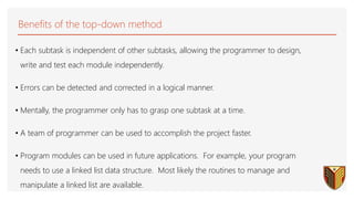
  • 49. Benefits of the top-down method • Each subtask is independent of other subtasks, allowing the programmer to design, write and test each module independently. • Errors can be detected and corrected in a logical manner. • Mentally, the programmer only has to grasp one subtask at a time. • A team of programmer can be used to accomplish the project faster. • Program modules can be used in future applications. For example, your program needs to use a linked list data structure. Most likely the routines to manage and manipulate a linked list are available.
  • 50. Statement of the problem Where it all starts. The highest level of abstraction • The statement of the problem to be solved Requires full analysis of the problem to be addressed and the system being designed to address it. 10/8/2021 ECE265 50
  • 51. An example of the methodology Where it all starts. The highest level of abstraction • The statement of the problem to be solved Requires full analysis of the problem to be addressed and the system being designed to address it.
  • 52. Assembler language programming • A good practice is never to program in assembler language directly. • Start with the specification of the module to be coded. • Code it in a Pseudo Design Language or PDL • PDL is much like any high-level programming language.
  • 53. Assembler Language • Assembler Language is specific to the machine (processor architecture). • Each processor version may have instructions that other versions do not have. • Assembler language has a 1-to-1 relationship with the machine language, i.e., executable code of the processor. • One assembler language statement • = • one executable instruction. 53
  • 54. Assembler language Usually, written line by line where each line is 80 character long. Within the 80-character line there are fields. Field position can be fixed. For example: • The first 10 characters are a label • The next field is for the operand or assembler directive • This is followed by the operand field • The last filed is for comments
  • 55. Boolean Logic & Logic Gates & Boolean Algebra
  • 56. Boolean algebra is a mathematical system for the manipulation of variables that can have one of two values. • In formal logic, these values are “true” and “false.” • In digital systems, these values are “on” and “off,” 1 and 0, or “high” and “low.” Boolean expressions are created by performing operations on Boolean variables. • Common Boolean operators include AND, OR, and NOT. Introduction
  • 57. Introduction cont. All switching devices we will use are two-state devices, so we will emphasize the case in which all variables assume only one of two values. Boolean variable X or Y will be used to represent input or output of switching circuit. Symbols “0” and “1” represent the two values any variable can take on. These represent states in a logic circuit, and do not have numeric value. Logic gate: 0 usually represents range of low voltages and 1 represents range of high voltages Switch circuit: 0 represents open switch and 1 represents closed 0 and 1 can be used to represent the two states in any binary valued system.
  • 58. Boolean Login & Login Gates
  • 59. Boolean Login & Login Gates
  • 60. Boolean Algebra Rules that govern constants and variables that can take on 2 values • True/false; on/off; yes/no; 0/1 Boolean logic • Rules for handling Boolean constants and variables • 3 fundamental operations: AND, OR and NOT • Truth Table: specifies results for all possible input combinations
  • 61.  A Boolean operator can be completely described using a truth table.  The truth table for the Boolean operators AND and OR are shown at the right.  The AND operator is also known as a Boolean product. The OR operator is the Boolean sum. Boolean Algebra
  • 62. A Boolean function has: • At least one Boolean variable, • At least one Boolean operator, and • At least one input from the set {0,1}. It produces an output that is also a member of the set {0,1}. Now you know why the binary numbering system is so handy in digital systems. Boolean Algebra
  • 63. We have looked at Boolean functions in abstract terms. In the next section, we’ll see that Boolean functions are implemented in digital computer circuits called gates. A gate is an electronic device that produces a result based on two or more input values. • In reality, gates consist of one to six transistors, but digital designers think of them as a single unit. • Integrated circuits contain collections of gates suited to a particular purpose. Boolean LOGIC GATES
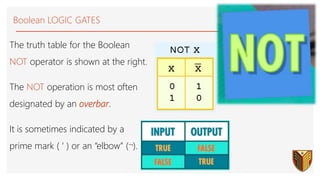
  • 64. The truth table for the Boolean NOT operator is shown at the right. The NOT operation is most often designated by an overbar. It is sometimes indicated by a prime mark ( ‘ ) or an “elbow” (). Boolean LOGIC GATES
  • 65. Boolean Login & Login Gates
  • 70. EXCLUSIVE OR a b a.b a b a+b a a' a b (a+b)' a b (a.b)' a b a  b a b a.b & a b a+b + AND a a' 1 a b (a.b)' & a b (a+b)' 1 a b a  b =1 OR NOT NAND NOR Symbol set 1 Symbol set 2 (ANSI/IEEE Standard 91-1984) Boolean LOGIC GATES
  • 73. Basic Operations • Also known as Switching Algebra › Invented by mathematician George Boole in 1849 › Used by Claude Shannon at Bell Labs in 1938 • T o describe digital circuits built from relays • Digital circuit design is based on › Boolean Algebra • Attributes • Postulates • Theorems › These allow minimization and manipulation of logic gates for optimizing digital circuits
  • 74. Basic Operations • Binary › A1a: X=0 ifX=1 › A1b: X=1 ifX=0 • Complement › aka invert,NOT › A2a: if X=0, X’=1 X Y X•Y 0 0 0 0 1 0 1 0 0 1 1 1 • AND operation › A3a:0•0=0 › A4a:1•1=1 › A5a: 0•1=1•0=0 - The dot • means AND - Other symbol forAND: X•Y=XY(no symbol) › A2b: if X=1, X’=0 - The tick mark ’ means complement,invert, or NOT - Other symbolfor complement: X’= X › A3b:1+1=1 › A4b:0+0=0 › A5b: 1+0=0+1=1 - The plus + means OR X Y X+Y 0 0 0 0 1 1 1 0 1 1 1 1 X X’ 0 1 1 0 • OR Operation 74
  • 75. BOOLEAN ALGEBRA ATTRIBUTES • Variable: Variables are the different symbols in a Boolean expression • Literal: Each occurrence of a variable or its complement is called a literal • Term:A term is the expression formed by literals and operations at one level – A, B, C are three variables – Eight Literals – Expression has five terms including four AND terms and the OR term that combines the first-level AND terms. 75
  • 76. Basic Operations Series Switching Circuits/ AND : 76 Series: A) Truth table B) Logic gate diagram C) Switch circuit diagram A) C) B) • The operation defined by the table is called AND. • It is written algebraically as C=A·B. • We will usually write AB or A·B. • The AND operation is also referred to as logical (or Boolean) multiplication.
  • 77. Basic Operations Parallel Switching Circuits/ OR Series: A) Truth table B) Logic gate diagram C) Switch circuit diagram If switches A and B are connected in parallel, there is a closed circuit if either A or B, or both, are closed and an open circuit only if A and B are both open. A) B) C) The operation defined by the table is called OR. It is written algebraically as C=A+B The OR operation is also referred to as logical (or Boolean) addition.
  • 78. Basic Operations Parallel Switching Circuits/ NOT Series: A) Truth table B) Logic gate diagram C) Switch circuit diagram A simple 2-input logic NOT gate can be constructed using a RTL Resistor-transistor switches as shown below with the input connected directly to the transistor base. The transistor must be saturated “ON” for an inverted output “OFF” at Q. A) B) C) The standard NOT gate is given a symbol whose shape is of a triangle pointing to the right with a circle at its end. This circle is known as an “inversion bubble” and is used in NOT, NAND and NOR symbols at their output to represent the logical operation of the NOT function. x ¬x 0 1 1 0 x x'
  • 79. Examples Boolean Logic Circuits When a Boolean expression is provided, we can easily draw the logic circuit. Examples: F1 = xyz' (note the use of a 3-input AND gate) x y z F1 z'
  • 80. Analyzing Logic Circuits When a logic circuit is provided, we can analyse the circuit to obtain the logic expression. Example: What is the Boolean expression of F4? A'B' A'B'+C (A'B'+C)' A' B' C F4 F4 = (A'B'+C)'