


![What's Meta data? [ so called data about data]
Information that describes and explains data is meta data.
It provides context with details such as the source, type,
owner, and relationships to other data sets etc.,](https://image.slidesharecdn.com/dbms22cs403unit1manjus-250326072324-65645771/85/DBMS-DATA-MANAGEMENT-SYSTEM-ppt-Cs403-rtc-10-320.jpg)


![Enhanced ER models [EER]
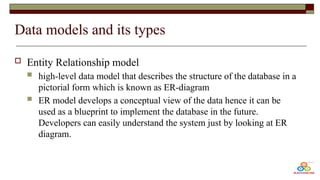
Today the complexity of the data is increasing so it becomes more and
more difficult to use the traditional ER model for database modeling
that help us create and maintain detailed databases through high-level
models and tools.
All the components of an ER diagram are included in an EER diagram,
with the following additions
Specialization and Generalization
Aggregation
Category or Union types
Subclass and superclass](https://image.slidesharecdn.com/dbms22cs403unit1manjus-250326072324-65645771/85/DBMS-DATA-MANAGEMENT-SYSTEM-ppt-Cs403-rtc-76-320.jpg)


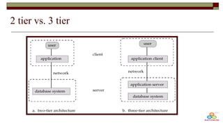
![Need for Foreign key ? Splitting tables?
Design 1
Design 2 [ inserting more rows]
Cannot insert more rows for a same
person as primary key wont allow and
also space utilized to save same data will
be high
Disadvantages:
A student might have one
number so other 2 columns
would be null
Design is inappropriate as it
might have more nulls.
RollNo Student
Name
Phone
Numbe
r1
Phone
Numbe
r2
Phone
Numbe
r3
Addres
s](https://image.slidesharecdn.com/dbms22cs403unit1manjus-250326072324-65645771/85/DBMS-DATA-MANAGEMENT-SYSTEM-ppt-Cs403-rtc-99-320.jpg)


![Database System Concepts AND architecture [Autosaved].pptx](https://cdn.slidesharecdn.com/ss_thumbnails/databasesystemconceptsandarchitectureautosaved-230817173311-be7f8590-thumbnail.jpg?width=560&fit=bounds)


![chapter 2-DATABASE SYSTEM CONCEPTS AND architecture [Autosaved].pdf](https://cdn.slidesharecdn.com/ss_thumbnails/chapter2-databasesystemconceptsandarchitectureautosaved-230512145134-613f7180-thumbnail.jpg?width=560&fit=bounds)


Ad
More Related Content
Similar to DBMS DATA MANAGEMENT SYSTEM ppt Cs403 rtc (20)
Recently uploaded (20)


Ad
DBMS DATA MANAGEMENT SYSTEM ppt Cs403 rtc
- 1. 03/26/2025 1 DATABASE MANAGEMENT SYSTEMS – CSE/IT – II Year / IV Sem. – 22CS403 Manju S, AP/CoE, RTC,Coimbatore. Manju.S/AP
- 2. 03/26/2025 2 TOPICS DBMS AND CONCEPTUAL DATA MODELING Purpose of Database System – Data independence - Data Models – Database System Architecture – Conceptual Data modeling: ER models - Enhanced-ER Model. Introduction to relational databases – Relational Model – Keys – ER-to-Relational Mapping. Modeling of a library management system
- 3. Traditional File Systems Its a manual way of storing data as “Files”. Considering a scenario of a bank before the introduction of DBMS, for example, say someone went to the bank to deposit a certain amount in their account. So as the DBMS is not available so the bank employee has to manually register their account number, name, and amount in either a written manner or type and store them locally in the computer as a file.
- 4. Problems with traditional File Systems The problem which might arise that while writing if the employee mistakenly writes any digit of their account number or amount wrong . Then there would be a major issue and as there is no Database so it would be really hard to know what was the last state of that person’s account before this miss happened deposit.
- 5. Traditional File Systems The files stored in different departments were independent of each other, which caused severe data redundancy. The traditional file system is way less flexible than DBMS The maintenance of those files was also of high cost Concurrency issues
- 6. Disadvantages of Traditional File Systems Distinguished and Isolated Data User needs information that is not possible to be provided using a single file, multiple different files were required, which are situated in different departments Data Duplication / Data Redundancy Storing the same data multiple times, Data integrity issues of all data being same Dependence on Data file’s format change triggers the need of programmers to update the code every time and format every piece of data stored in that file
- 7. Disadvantages of Traditional File Systems Data representation is challenging from the user’s perspective Concurrency issues Two or more users can view the same file simultaneously, but the problem arises when they try to update the same file simultaneously Data Protection Manual storing of data provides easy access of confidential data by unauthorized parties
- 8. Data independence The ability to modify the schema definition of a DBMS at one level, without affecting the schema definition of the next higher level is called data independence Data independence aids in the separation of data from the applications that use it. Schema : Overall structure of the data
- 9. Why Data Independence? In addition to the data entered by users, a database system typically holds a large amount of data. The system holds metadata about data which makes it easier to find and retrieve data. Once a set of metadata in DBMS has been saved in a database, changing or updating the metadata is challenging. However, as a database management system (DBMS) grows, it must evolve to meet the needs of its users Updating the schema or data would be a time-consuming and complicated task if all of the data were dependent. To address the problem with updating metadata, it is organized in a tiered structure, so that changing data at one level does not affect data at another.
- 10. What's Meta data? [ so called data about data] Information that describes and explains data is meta data. It provides context with details such as the source, type, owner, and relationships to other data sets etc.,
- 11. Purpose of Database Systems Reduced Redundancy and inconsistency in the data Data Exchange Concurrent Data Searching Data Data Reliability Data Protection Recovery from system failures Maintenance of the Database
- 13. 3 level architecture View or External level : users can view their desired data from this level which is internally fetched from database Logical or Conceptual Level : whole design of the database such as relationship among data, schema of data etc. are described in this level. Physical or Internal Level : describes how the data is actually stored in the storage devices. This level is also responsible for allocating space to the data.
- 14. Types of Data Independence 2 types of data independence Logical data independence : ability to modify logical schema without causing any unwanted modifications to the external schema/level Physical data independence : ability to modify the physical schema of the database without the modification causing any changes in the logical/conceptual or view/external level.
- 15. Types of Data Independence Logical data independence Physical data independence
- 16. Examples of data independence Physical Data Independence Changing from one data structure to another. Making use of new storage technology, such as a hard drive or magnetic tapes Change the location of the database from one drive to another. Changing the database's file organization. Logical Data Independence Without rewriting current application scripts, you can add, modify, or delete a new attribute, entity, or relationship. To divide an existing record into two or more records. Merging two records into a single one
- 17. Just to know! We are only talking about the changes in the schema at a lower level affecting the schema at the higher levels because changing anything at a higher level can never affect the schema at a lower level. And since the view or external level is the highest level, there is no data independence type associated with it, because there are no levels above it.
- 18. Data models Data models in DBMS helps to understand the design at the conceptual, physical, and logical levels It provides a clear picture of the logical structure of the database Data models are used to describe how the data is stored, accessed, and updated in a DBMS. Types include, Hierarchical Model Network Model Entity-Relationship Model (ER Model) Relational Model Object-Oriented Data model Object Relational Data Model
- 19. Data models and its types Hierarchical model One of the oldest data models, developed in the 1950s by IBM. In this data model, the data is organized in a hierarchical tree-like structure Drawback : One to many relationships under this model, hence the hierarchical data model is very rarely used nowadays
- 20. Data models and its types Network model represented as a graph and hence it replaces the hierarchical tree with a graph in which object types are the nodes and relationships are the edges. Many possible paths exists to reach a node from the root node, therefore the data can be accessed efficiently But, on the other hand, the process of insertion and deletion of data is quite complex
- 21. Data models and its types Relational Model Widely accepted data model where the database is represented as a collection of relations in the form of rows and columns of a two-dimensional table. Each row is known as a tuple (a tuple contains all the data for an individual record) while each column represents an attribute. Relation "STUDENT" with attributes such as Stu. Id, Name, and Branch which consists of 4 records or tuples. Stu. Id Name Branch 101 Naman CSE 102 Saloni ECE 103 Rishabh IT 104 Pulkit ME
- 22. Data models and its types Object-Oriented Data model combination of object-oriented programming and relational data model. Here, data and their relationship are represented in a single structure which is known as an object. Since data is stored as objects we can easily store audio, video, images, etc. in the database which was very difficult and inconvenient to do in the relational model
- 23. Data models and its types Object Relational Data Model Integration of the object-oriented model and the relational model. Since it inherits properties from both of the models it supports objects, classes, etc. like object- oriented models, and tabular structures like the relational model. Complex and quite difficult to handle
- 24. Data models and its types Entity Relationship model high-level data model that describes the structure of the database in a pictorial form which is known as ER-diagram ER model develops a conceptual view of the data hence it can be used as a blueprint to implement the database in the future. Developers can easily understand the system just by looking at ER diagram.
- 25. Entity Relationship model Entity - Anything that has an independent existence about which we collect the data. They are represented as rectangles in the ER diagram. For example - Car, house, employee. Entity Set - A set of the same type of entities is known as an entity set. For example - Set of students studying in a college. Attributes Properties that define entities are called attributes. They are represented by an ellipse shape. Relationships – A relationship in DBMS is used to describe the association between entities. They are represented as diamond in the ER diagram.
- 26. Entity Relationship model We have two entities that are Employee and Company, and the relationship among them. Also, in the represented ER diagram, we can see that both the employee and company have some attributes and the relationship is of "works in" type, which means the employee works in a company
- 27. Database architecture & types DB architecture is crucial for efficient data management and system performance. It involves the database's design, development, and maintenance, determining how users interact with and access the system.
- 28. DBA : One tier Here, database is directly available to the user. It means the user directly sits on the DBMS and uses it. Any changes done here will directly be done on the database itself. The 1-Tier architecture is used for development of the local application, where programmers can directly communicate with the database for the quick response. Use case : The data isn't changed frequently. No multiple users are accessing the database system. We need a direct and simple way to modify or access the database for application development.
- 29. DBA : One tier : Example In order to learn the Structure Query Language (SQL), we set up our SQL server and the database on our local system. This SQL server enables us to directly interact with the relational database and execute certain operations without requiring any network connection
- 30. DBA : One tier : Use Case The data isn't changed frequently. No multiple users are accessing the database system. We need a direct and simple way to modify or access the database for application development.
- 31. DBA : 2 tier Similar to the basic client-server. Here, applications on the client end can directly communicate with the database on the server side. For this interaction, APIs like ODBC, and JDBC are used. The user interfaces and application programs run on the client side. The server side is responsible to provide the functionalities like query processing and transaction management. To communicate with the DBMS, the client-side application establishes a connection with the server side
- 32. DBA : 2 tier : Use case Multiple users can use it at the same time. Hence, it can be used in an organization. It has high processing ability as the database functionality is handled by the server alone. Faster access to the database due to the direct connection and improved performance. Because of the two independent layers, it's easier to maintain.
- 33. DBA : 2 tier : Example Consider a situation where you went to a bank to withdraw some cash. After entering the withdrawal amount and the account details on the withdrawal slip, the banker will go through the server-side database via his credential (API call) and will check whether there is enough balance present or not. Disadvantages Scalability - As the number of clients increases, the load on the server increases. Thereby declining the performance of the DBMS and, in turn, the client-side application. Security - The Direct connection between the client and server systems makes this architecture vulnerable to attacks.
- 34. DBA : 3 Tier 3-Tier architecture contains another layer between the client and server. In this architecture, the client can't directly communicate with the server. The application on the client end interacts with an application server which further communicates with the database system. The end-user has no idea about the existence of the database beyond the application server. The database also has no idea about any other user beyond the application. The 3-Tier architecture is used in the case of the large web application.
- 35. DBA : 3 Tier Scalability - Since the database server isn't aware of any users beyond the application layer and the application layer implements load balancing, there can be as many clients as you want. Data Integrity - Data corruption and bad requests can be avoided because of the checks performed in the application layer on each client request. Security - The removal of the direct connection between the client and server systems via abstraction reduces unauthorized access to the database.
- 36. DBA : 3 Tier : Example A web-based application where users interact with a web browser (presentation layer), the server-side application (application layer) handles business logic and communicates with the database server (data layer) that stores the data. Imagine an e-commerce website where users browse products, add them to their cart, and place orders. The user’s browser communicates with a web server running a technology like ASP.NET, PHP, or Java EE, which processes user requests, executes business logic, and retrieves or updates data in the SQL database server (like MySQL, PostgreSQL, or MongoDB) as needed.
- 37. 2 tier vs. 3 tier
- 39. DBMS overall Architecture DBMS means Database Management System, which is a tool or software used to create the database or delete or manipulate the database. A software program created to store, retrieve, query, and manage data is known as a Database Management System (DBMS).
- 40. DBA overall Architecture Three parts that make the DBMS system Query Processor Storage Manager Disk Storage Query Processor (QP) query processor's primary duty is to successfully execute the query. The QP transforms (or interprets) the user's application program- provided requests into instructions that a computer can understand.
- 41. Components of Query Processor
- 42. DBA overall Architecture DDL Interpreter: Data Definition Language, the DDL Interpreter interprets DDL statements like those used in schema definitions (such as create,alter remove, etc.). This interpretation yields a set of tables that include the meta-data (data of data) that is kept in the data dictionary. Metadata may be stored in a data dictionary.
- 43. DBA overall Architecture DML Compiler: Compiler for DML Data Manipulation Language is what DML stands for. DML Compiler converts DML statements like select, insert, update, and delete into low-level instructions or simply machine-readable object code, to enable execution. The optimization of queries is another function of the DML compiler.
- 44. DBA overall Architecture Query Evaluation engine This engine will execute low-level instructions generated by the DML/DDL compiler on DBMS
- 45. DBA overall Architecture Storage manager a program module which acts like interface between the data stored in a database and the application programs and queries submitted to the system. Thus, the storage manager is responsible for storing, retrieving and updating data in the database
- 46. Components of Storage Manager
- 47. DBA overall Architecture Integrity and Authorization Manager tests for the satisfaction of integrity constraints and checks the authority of users to access data. File Manager: which manages the allocation of space on disk storage and the data structures used to represent information stored on disk. Transaction Manager : ensures that the database remains in a consistent (correct) state despite system failures, and that concurrent transaction executions proceed without conflicting Buffer Manager responsible for fetching data from disk storage into main memory, and deciding what data to cache in main memory. The buffer manager is a critical part of the database system, since it enables the database to handle data sizes that are much larger than the size of main memory.
- 48. DBA overall Architecture How data are stored in DB? Data files: Stored in the database itself. Data dictionary: Stores metadata about the structure of the database. Indices: Provide fast access to data items. Like the index in any textbook, a database index provides pointers to those data items that hold a particular value
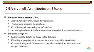
- 49. DBA overall Architecture : Users Database Administrator (DBA) Administering primary/ secondary resources. Authorizing access to the database. Coordinating & monitoring use of database. Acquiring hardware & Software resources as needed, Routine maintenance. Database Designers Identifying the data to be stored in the database. Choosing appropriate structures/schema to represent the stored data. Communicating with database users to understand their requirements and designs database.
- 50. DBA overall Architecture : Users Naive users are unsophisticated users who interact with the system by invoking one of the application programs Sophisticated users interact with the system without writing programs. Instead, they form their requests either using a database query language. Application programmers are computer professionals who write application programs. Application programmers can choose from many tools to develop user interfaces.
- 51. Conceptual data modelling A conceptual data model aims to capture high-level entities and relationships without delving into details such as specific database technologies or data types So in a conceptual data model, when you see an entity type called car, then you should think about pieces of metal with engines, not records in databases. Use Case: Understandability: It helps stakeholders understand the domain without needing to know the technical intricacies of database systems. Communication Tool: Acts as a bridge between non-technical stakeholders and developers by providing a common language. Framework for the Development: Serves as a guide for the development of Logical Data Models (LDMs) and Physical Data Models (PDMs).
- 52. Conceptual data modelling : 2 Notations Entity-Relationship Diagrams (ERDs): The most common tool used for conceptual data modeling. ERDs visually represent entities, their attributes, and relationships. Unified Modeling Language (UML): Though more often used in software development for modeling software systems, UML can also be used for data modeling, particularly with class diagrams
- 53. Entity Relationship model Entity Relational Model is a model for identifying entities to be represented in the database and representation of how those entities are related. Entity Relationship Diagram explains the relationship among the entities present in the database
- 54. Symbols and components of ER Diagram
- 55. Entity Relationship diagrams Entity may be an object with a physical existence – a particular person, car, house, or employee – or it may be an object with a conceptual existence – a company, a job, or a university course. Entity Set: An Entity is an object of Entity Type and a set of all entities is called an entity set. For Example, E1 is an entity having Entity Type Student and the set of all students is called Entity Set
- 56. Entity Relationship diagrams Strong Entity Type of entity that has a key Attribute. Strong Entity does not depend on other Entity in the Schema. It has a primary key, that helps in identifying it uniquely, It is represented by a rectangle. E.g. Adhaar ID, Student ID etc., Weak Entity An Entity type for which key attributes can’t be defined. A weak entity type is represented by a Double Rectangle They will depend on other entity for unique identification
- 57. Entity Relationship diagrams Example : A company may store the information of dependents (Parents, Children, Spouse, Brother, Sister) of an Employee. But the dependents don’t have existed without the employee. So Dependent will be a Weak Entity Type and Employee will be Identifying Entity type for Dependent, which means it is Strong Entity Type
- 58. Attributes : Attributes are the properties that define the entity type. For example, Roll_No, Name, DOB, Age, Address, and Mobile No are the attributes that define entity type Student. In ER diagram, the attribute is represented by an oval. Key Attribute The attribute which uniquely identifies each entity in the entity set is called the key attribute. For example, Roll_No will be unique for each student. In ER diagram, the key attribute is represented by an oval with underlying lines. Entity Relationship diagrams
- 59. Composite Attribute An attribute composed of many other attributes is called a composite attribute. For example, the Address attribute of the student Entity type consists of Street, City, State, and Country. Name(First, Mid and Last), DOB(Month,Day,Year) In ER diagram, the composite attribute is represented by an oval comprising of ovals. Multivalued Attribute An attribute consisting of more than one value for a given entity. For example, Phone_No (can be more than one for a given student). In ER diagram, a multivalued attribute is represented by a double oval. Entity Relationship diagrams
- 60. Entity Relationship diagrams Derived Attribute An attribute that can be derived from other attributes of the entity type is known as a derived attribute. E.g.; Age (can be derived from DOB). In ER diagram, the derived attribute is represented by a dashed oval.
- 61. Entity Relationship diagrams Relationship Type and Relationship Set Relationship Type represents the association between entity types. For example, ‘Enrolled in’ is a relationship type that exists between entity type Student and Course. In ER diagram, the relationship type is represented by a diamond and connecting the entities with lines.
- 62. Entity Relationship diagrams Degree of a Relationship Set The number of different entity sets participating in a relationship set 1. Unary Relationship When there is only ONE entity set participating in a relation, the relationship is called a unary relationship. For example, one person is married to only one person.
- 63. Entity Relationship diagrams 2. Binary Relationship There are TWO entities set participating in a relationship. For example, a Student is enrolled in a Course. 3. n-ary Relationship: When there are n entities set participating in a relation, the relationship is called an n-ary relationship.
- 64. Entity Relationship diagrams Ternary Relationships (3-entity relationships) Example: Project Allocation Entities: Student, Project, Supervisor Relationship: Allocation Quaternary Relationships (4-entity relationships) Example: Medical Prescription Entities: Patient, Doctor, Medication, Pharmacy Relationship: Prescription
- 65. Entity Relationship diagrams Cardinality The number of times an entity of an entity set participates in a relationship set is known as cardinality. Cardinality can be of different types: 1.One-to-One: When each entity in each entity set can take part only once in the relationship, the cardinality is one-to-one. Let us assume that a male can marry one female and a female can marry one male. So the relationship will be one-to-one or a surgeon headed by one head.
- 66. Entity Relationship diagrams 2. One-to-Many: In one-to-many mapping as well where each entity can be related to more than one relationship . Let us assume that one surgeon department can accommodate many doctors. So the Cardinality will be 1 to M. It means one department has many Doctors.
- 67. Entity Relationship diagrams 3. Many-to-One: When entities in one entity set can take part only once in the relationship set and entities in other entity sets can take part more than once in the relationship set, cardinality is many to one. Let us assume that a student can take only one course but one course can be taken by many students. So the cardinality will be n to 1. It means that for one course there can be n students but for one student, there will be only one course.
- 68. Entity Relationship diagrams 4. Many-to-Many: When entities in all entity sets can take part more than once in the relationship cardinality is many to many. Let us assume that a student can take more than one course and one course can be taken by many students. So the relationship will be many to many
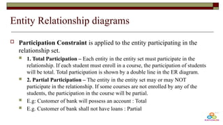
- 69. Entity Relationship diagrams Participation Constraint is applied to the entity participating in the relationship set. 1. Total Participation – Each entity in the entity set must participate in the relationship. If each student must enroll in a course, the participation of students will be total. Total participation is shown by a double line in the ER diagram. 2. Partial Participation – The entity in the entity set may or may NOT participate in the relationship. If some courses are not enrolled by any of the students, the participation in the course will be partial. E.g: Customer of bank will possess an account : Total E.g. Customer of bank shall not have loans : Partial
- 70. Entity Relationship diagrams Students to curriculum subjects Students to Hybrid classes or Dual Degree courses offered in our college Total Participation i.e. Every student must enroll for the courses Partial Participation i.e. There shall be any courses without students being enrolled
- 71. Guess what?! Cardinality ! Human being to Senses? Indian to Adhaar ID? Customer to Orders? Order to Items/Products? Students to courses ? • 1 to Many • One to one • One to many • One to many • Many to many
- 72. Relationships using sets : Guess it! 1 to 1 Many to 1 1 to many Many to many
- 73. To do! Develop a ER diagram for student and staff management system with respect to the courses and projects Develop a ER diagram for banking system . Bank have Customer. Banks are identified by a name, code, address of main office. Banks have branches. Branches are identified by a branch_no., branch_name, address. Customers are identified by name, cust-id, phone number, address. Customer can have one or more accounts. Accounts are identified by account_no., acc_type, balance. Customer can avail loans. Loans are identified by loan_id, loan_type and amount. Account and loans are related to bank’s branch.
- 74. Can any relationships in ER have attributes? Yes! Relationships can also have attributes associated to them which generally is not recommended because it would be difficult in converting it to relational model.
- 75. Can any relationships in ER have attributes? “Student borrows a Book” How would you draw ER? Student and Book would be entity. Borrow would be a relationship where as DateBorrowed, DueDate shall be the attributes related to borrowing a book.
- 76. Enhanced ER models [EER] Today the complexity of the data is increasing so it becomes more and more difficult to use the traditional ER model for database modeling that help us create and maintain detailed databases through high-level models and tools. All the components of an ER diagram are included in an EER diagram, with the following additions Specialization and Generalization Aggregation Category or Union types Subclass and superclass
- 77. Enhanced ER models Subclasses and Super class Super class is an entity that can be divided into further subtype. For example − Consider Shape : super class Super class shape has sub groups: Triangle, Square and Circle. Sub classes are the group of entities with some unique attributes. Sub class inherits the properties and attributes from super class.
- 78. Enhanced ER models Generalization and Specialization: Specialized classes are often called subclass while a generalized class is called a superclass, probably inspired by object-oriented programming. A sub-class is best understood by “IS-A analysis”. Specialization : is a process of identifying subsets of an entity that share some different characteristic. It is a top down approach in which one entity is broken down into low level entity. Generalization : bottom up approach, combination of entities
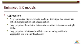
- 79. Enhanced ER models Aggregation Aggregation is a high-level data modeling technique that makes use of both Generalization and Specialization. In aggregation, the relation between two entities is treated as a single entity. In aggregation, relationship with its corresponding entities is aggregated into a higher level entity.
- 80. Enhanced ER models Center entity offers the Course entity act as a single entity in the relationship which is in a relationship with another entity visitor. In the real world, if a visitor visits a coaching center then he will never enquire about the Course only or just about the Center instead he will ask the enquiry about both.
- 81. Enhanced ER models Category or Union : represents a single super-class or sub-class relationship with multiple super-classes. Participation can be total or partial. The Car Owner in the Car booking model can be a Person, a bank, or a company. The Owner (category- subclass) is the union of the three superclasses Company, Bank, and Person. A member of a Category must exist in at least one of its superclasses
- 82. Relational Databases The term "relational database" was invented at IBM by E. F. Codd in the 1970 Relational databases represents data in simple logical constructs called tables or relations which are based on the set theory. To a user, a relational database is perceived as a collection of several well-organized relations. Each table corresponds to an independent entity
- 83. Relational Databases Relation / table is a collection of rows and columns The objects of which we desire to store the data of, are stored in relations as rows that represent individual records Columns that represent characteristics called attributes of the object. A column, that represents the properties of an object, holds a value for every record in a certain format. These values must conform to the domain from which they were assigned. Data in a relation may be retrieved by a query, which is a statement from a data language, which is a non-procedural language because it is not mandatory to specify the procedure that must be followed to get the work done.
- 84. Relational Model The relational model in DBMS is an abstract model used to organize and manage the data stored in a database. It stores data in 2-dimensional inter-related tables, also known as relations in which each row represents an entity and each column represents the properties of the entity EmpNo EmpName Age Dept 1000 Jacob 22 SE 1001 William 23 Fin 1002 Jon 24 HR 1003 Harrold 19 Fin
- 85. Keys Keys are one of the basic requirements of a relational database model. It is widely used to identify the tuples(rows) uniquely in the table Primary key Foreign Key Super Key Candidate Key Alternate Key Composite key
- 86. Why keys? Helps with unique identification of data Helps to avoid redundancy It is also used to establish and identify relationships between tables.
- 87. Primary Key Any attribute that uniquely identifies a record in a table. E.g. : RegNo. In Student table, Adhaar ID of Indians (When Adhaar is mandated), SSN of Americans, EmpId of an Employee etc.,
- 88. Right or Wrong?! Guess Can we can think of License No. or Passport No. as Primary key!?? No! that cant be taken as Primary key! Reason : We cant assure every student or an employee of student table or employee table will possess passport or driving license. But when you are an employee or student the respective ids are mandated!
- 89. Candidate Key A candidate key is an attribute or set of attributes that can uniquely identify a tuple. Except for the primary key, the remaining attributes are considered a candidate key. The candidate keys are as strong as the primary key. In the EMPLOYEE table, id is best suited for the primary key. The rest of the attributes, like SSN, Passport_Number, License_Number, etc., are considered a candidate key Minimal super key is candidate key
- 90. Super Key Super key is an attribute set that can uniquely identify a tuple. A super key is a superset of a candidate key. In the above EMPLOYEE table, for(EMPLOEE_ID, EMPLOYEE_NAME), the name of two employees can be the same, but their EMPLOYEE_ID can't be the same. Hence, this combination can also be a key
- 91. Super Key Vs. Candidate Key Assume a College that follows the following pattern of giving rollnos for students. Students are given unique rollnos. in a department starting from 1 and same pattern continues for other departments. So to uniquely identify a student in a college we need 2 attributes for sure say rollno and department. Super key shall be {rollno., department_id, adhaar no., Phone no.} Candidate key will be {rollno.,department_id} And hence minimal super key is candidate key!!
- 92. Relation between Super, Candidate and Primary keys
- 93. Lets game for keys! Guess it yes or no! Is super key a candidate key? Is a candidate key a super key? Is a primary key a candidate key? Is a candidate key a primary key? Is a primary key a super key? Is a super key a primary key? • No • Yes • Yes • No • Yes • No
- 94. Super vs. Primary Key Super Key Primary Key Super Key is an attribute (or set of attributes) that is used to uniquely identify all attributes in a relation. Primary Key is a minimal set of attribute (or set of attributes) that is used to uniquely identifies all attributes in a relation. All super keys can’t be primary keys. Primary key is a minimal super key. In a relation, number of super keys are more than number of primary keys. While in a relation, number of primary keys are less than number of super keys. Super key’s attributes can contain NULL values. Primary key’s attributes cannot contain NULL values.
- 95. Composite key Whenever a primary key consists of more than one attribute, it is known as a composite key. This key is also known as Concatenated Key. Say we follow roll number system that starts with 1 for each department and department has unique department id. Then to uniquely identify a student we need his/her rollno. and department id So Roll no. and department id together acts as primary key which is composite..
- 96. And back again with game of keys!! Is super key a composite key? Is candidate key a composite key? Is primary key a composite key? • A super key/candidate key/primary key can be a composite key if it includes two or more attributes necessary for unique identification.
- 97. Foreign key A FOREIGN KEY is a field (or collection of fields) in one table, that refers to the PRIMARY KEY in another table. The table with the foreign key is called the child table, and the table with the primary key is called the referenced or parent table A FOREIGN KEY is a column that is used to create a link between two tables
- 98. Need for Foreign key ? Splitting tables? Imagine we have to create a student database where you will have to save Student name, Roll no., and their personal data like phone number, address. Also imagine a student shall have a varied number of mobile numbers say from 1,2, to 3. How would you design your database?
- 99. Need for Foreign key ? Splitting tables? Design 1 Design 2 [ inserting more rows] Cannot insert more rows for a same person as primary key wont allow and also space utilized to save same data will be high Disadvantages: A student might have one number so other 2 columns would be null Design is inappropriate as it might have more nulls. RollNo Student Name Phone Numbe r1 Phone Numbe r2 Phone Numbe r3 Addres s
- 100. And hence splitting tables! The single table can be split into 2 (Parent and Child) tables. Student : {Rollno., Student_Name, Address} : Rollno. Acts as Primary Key StudentContact : {RollNo., Phone Number} : Rollno. Acts as a Foreign Key RollNo Student Name Address RollNo Phone Number Parent Table Child Table
- 101. Foreign Key Same shall happen for customers and orders. A customer shall have placed 15 orders while a customer shall not have any orders been places. So customer data and order related to customer has to separated into different tables. Always be sure that foreign keys shall have repetition while the same key attribute as a primary key in parent table cannot have repetition!
- 102. Alternate Key An alternate key is none other than a candidate key, so the use/role of an alternate key is the same It means an alternate key is also used to identify those columns in a table that can uniquely identify all the records of the table. E.g..: Student mail id or Employee mail_id shall be taken as alternate keys. Shall be considered as an alternate or secondary option when primary key fails!
- 103. Alternate Key
- 104. Why so many keys?! Initially when DB design happens , designers think of all attributes (key attributes) which have a capability to act as primary key of any table And hence the decision happens by generating a super key first and then a candidate key next. Of the generated candidate keys, only one key will selected as the primary key. Thus, the other remaining keys are known as Alternate Keys or Secondary Keys.
- 105. ER to relational mapping This process involves transforming the entities, relationships, and attributes represented in the ER diagram into tables that can be implemented in a relational database management system like PSQL, MySQL, Oracle etc
- 106. ER to relational mapping 1. Entities to Tables: Rule: Each entity in the ER diagram becomes a table in the relational model. Details: The attributes of the entity become the columns of the table. The primary key of the entity becomes the primary key of the table. ER Diagram Entity: User (UserID, Name, Email) Relational Model: Table: User Columns: UserID (PK), Name, Email
- 107. ER to relational mapping 2. Primary Keys: Rule: Every entity in the ER diagram must have a primary key, and this primary key will be carried over to the relational table. Details: The primary key uniquely identifies each record in the table. Entity: Product (ProductID, Name, Price) Relational Model: Table: Product Columns: ProductID (PK), Name, Price
- 108. ER to relational mapping 3. Composite Attributes: Rule: Composite attributes are flattened out. Details: Instead of having a hierarchical structure, each attribute that is part of the composite attribute becomes its own column in the table. ER Diagram Entity: Address (Street, City, State, Country) Relational Model: Table : User Columns: UserID, Name, Email, Street, City, State, Country
- 109. ER to relational mapping 4. Multi-valued Attributes: Rule: Create a separate table for each multi-valued attribute. Details: This new table will include a column for the attribute values and a column to serve as a foreign key linking back to the original table. ER Diagram Entity: Student (StudentID, Name, Phoneno.) Relational Model: Table 1: Student Columns: StudentID (PK), Name Table 2: Email Columns: StudentID (FK), phoneno.
- 110. ER to relational mapping 5. Weak Entities: Rule: Weak entities become their own tables. Details: The primary key of the weak entity table is a combination of its own partial key and the primary key of the owning entity. This combined key serves as the primary key of the weak entity table. ER Diagram Entity: Student (StudentID, Name), Parents(Name,Contact) Relational Model: Table 1: Student Columns: StudentID (PK), Name Table 2: Student_Parent Columns: StudentID (FK), Parents_Name, Contact Primary Key (PK): (StudentID,Parents_Name)
- 111. ER to relational mapping 6. Relationships: One-to-One (1:1): Represent as a foreign key in one of the tables. The side to hold the foreign key can be decided based on the business rules or constraints. One-to-Many (1:N): Represent by adding a foreign key to the table on the "many" side of the relationship, linking back to the "one" side. Many-to-Many (M:N): Create a new table to represent the relationship. This table should include foreign keys that reference the primary keys of the two entities involved in the relationship. The primary key of this new table could be a composite of these foreign keys.
- 112. ER to relational mapping One-to-One (1:1) Relationship: ER Diagram Relationship: User has one Passport (User: UserID, Passport: PassportID) Relational Model: Table: User Columns: UserID (PK), PassportID (FK) Table: Passport Columns: PassportID (PK)
- 113. ER to relational mapping One-to-Many (1:N) Relationship: ER Diagram Relationship: A Department has many Employees Relational Model: Table: Department Columns: DepartmentID (PK) Table: Employee Columns: EmployeeID (PK), DepartmentID (FK)
- 114. ER to relational mapping Many-to-Many (M:N) Relationship: ER Diagram Relationship: Students enroll in many Courses; a Course has many Students Relational Model: Table: Student Columns: StudentID (PK) Table: Course Columns: CourseID (PK) Table: Enrollment Columns: StudentID (FK), CourseID (FK) Primary Key (PK): (StudentID, CourseID)
- 115. ER to relational mapping 7. Attributes on Relationships ER Diagram Relationship with Attributes: Student borrows a Book; Borrow (DateBorrowed, DueDate) Relational Model: Table: Student Table: Book Table: Borrow Columns: StudentID (FK), BookID (FK), DateBorrowed, DueDate Primary Key (PK): (StudentID, BookID)
- 116. ER to relational mapping 8. Generalization and Specialization (Inheritance) ER Diagram Entities: Person (PersonID, Name), Employee extends Person (Salary, Department) Relational Model: Table per Type: Table: Person Columns: PersonID (PK), Name Table: Employee Columns: PersonID (PK/FK),EmployeeID, Salary, Department
- 117. To do! Give a ER diagram for modelling library management system Also convert the same into relational models. Use appropriate entities and relationships to model the actual library management happenings!
- 118. Thank you!