SlideShare a Scribd company logo
Cloud Platforms
Cloud computing platforms
Reference:
• https://www.openstack.org/
• Book: ‘OpenStack Essentials’ by Dan Radez
Recap: The Cloud (for now)
• For now, the cloud is an infrastructure
offering the possibility to create VMs
• Such infrastructure is designed, deployed and
maintained by the cloud provider, which sell
virtualized resources for profit
• On top of VMs cloud applications are
deployed (by cloud consumers), whose
services are offered to end-users, in some
cases for profit
• We know how a VM can be created on a
single machine using virtualization
technologies
• What is a cloud computing infrastructure?
How do we manage to create an
infrastructure that allows to create and
control a large number of VMs on a large
scale?
The cloud infrastructure
• Recent virtualization technologies allow VMs to be created on top of regular hardware, a powerful server
can support the creation of multiple VMs running at the same time on the same hardware
• The cloud infrastructure exploits regular (unmodified) hardware to support the creation of VMs, it does not
require any specific modified hardware
• A group of servers is
interconnected via a high
speed LAN comprises the
cloud infrastructure
• Eventually the group of
servers is connected to the
Internet via a router, so each VM
can communicate with the users and
viceversa
• This group of servers and the
LAN are deployed on an
appropriate environment, the
datacenter
• On each server a hypervisor
is installed
Internet
Cloud Platform
• A pool of servers, each one running a hypervisor, are federated to create a cloud
platform
• The cloud platform is a distributed system (it can be considered a special type of cloud
application) that controls the hypervisors of all the servers in the infrastructure
• It manages the instantiation/destruction of VMs on the infrastructure, i.e. at any
moment it controls which WMs has to be executed on which server and with which
properties
• In order to allow the management of VMs, the platform exposes a management
interface
• Such interface can be used by humans to control the generation of VMs or by a software
to automate the control of the cloud infrastructure (e.g. to create/destroy VMs to
accommodate load fluctuations)
• The cloud platform allows to implement the IaaS cloud model as it enables the
creation/destruction of VMs
• On top of such infrastructure more complex models (PaaS and SaaS) can be deployed
General Architecture
• The overall architecture is simple: a set of servers are
connected to a high speed local area network (Ethernet
LAN > 10Gbps)
• Each server has an operating system installed on top of the
bare metal (the physical hardware)
• A hypervisor is installed on the OS to virtualize the physical
resources offered by the servers
• In addition to the hypervisor a cloud platform software is
installed to control the local resources virtualized by the
hypervisor. This software is often referred as the agent of
the cloud platform
• In order to implement system wide management and
control functionalities of the cloud platform on one (or
more to ensure resiliency) server, a particular instance of
the cloud platform software is installed. This software is
often referred as cloud platform controller. This software
can be installed on a server that does not have a hypervisor
or it could be even installed on a virtual machine. The
software is responsible for controlling the overall platform
communicating with the agents
Hardware/Bare Metal
Operating System
Hypervisor
Cloud Platform
Agent
VM
VM
Cloud Platform
Controller
Cloud Platform
Agent
Cloud Platform
Agent
Cloud Platform
Agent
Cloud Platform Implementations
• Different public or private cloud platform implementation are
available today: some of them are commercial other are open-source
• Currently, we do not have a standard for the architecture of cloud
platforms, however, their architecture is very similar, so taking a look
at the architecture of one is sufficient to understand the other
implementations
• Public cloud internals (e.g. Google cloud, Microsoft Azure, Amazon
AWS) are hidden, however, they have a similar architecture to the one
available on the market
• In this course we take a look at the architecture and functionalities of
one cloud platform: OpenStack
OpenStack
• OpenStack is a free open-source
software platform for IaaS cloud
computing
• Started as a joint project of Rackspace
Hosting and of NASA in 2010
• Openstack today is supported and
managed by the OpenStack
Foundation, which composed by
more than 500 companies (e.g.
VMware, CISCO, Citrix, Oracle,
Ericsson, IBM, etc)
• It is the main solution adopted for
private cloud computing
OpenStack @ CERN
OpenStack is widely adopted today by
companies to build large public/private cloud
deployments.
Other User Stories:
https://www.openstack.org/user-stories/
OpenStack Software Platform
• OpenStack runs on top of commodity server (no
particular hardware is required)
• The software platform is installed on each server and
runs on top of the host operating system.
• The platform can run only on the Linux OS, while it
supports multiple hypervisor technologies
• Through each hypervisor, OpenStack creates/destroys
the VMs
• Every server that has installed the OpenStack
software (or a part of it) is called OpenStack Node
• The platform manages the connection of VMs to
Virtual Networks, which can be used to communicate
with other VMs or with external networks
• In addition to Virtual Machines and Virtual Networks,
the platform manages the Storage. This enable the
creation of virtual hard drives that can be connected
to virtual machines
Hardware
Linux Operating System
VM1 VM2 VM3
Hypervisor
OpenStack
Virtual Network
OpenStack Instance
• Nodes running the OpenStack software are
configured to form a single OpenStack
instance combining together computing,
memory and storage capabilities to create VMs
• In a single instance, at least one node is
configured as controller which is in charge of
coordinating OpenStack functions and
managing the resources available to the
instance
• Other nodes are configured as compute nodes
that offer computation and storage resources
to run virtual machines
• Nodes are connected through a (real) high
speed local area network, which is used as
• infrastructure on top of which the Virtual
Networks are created
• communication network used by the OpenStack
components to communicate for coordination
and management
Linux Operating System
Management and
Coordination Services
Openstack Controller
VM1 VM2
Openstack Compute
VM1 VM2
Openstack Compute
Real LAN
OpenStack Architecture
• The platform exposes a web
dashboard to allow users and
administrators to manage virtual
resources, i.e. VMs, Virtual
Networks and Virtual Hard
Drives
• An interface based on REST APIs
is also offered as machine-
friendly interface
• Such APIs can be used by
external programs
• A command line
interface is also
offered
OpenStack Architecture
• The OpenStack software is highly modular:
• The functionalities of the platform are grouped into services: e.g. the compute service to manage the
creation of VMs, the network service to manage the creation of Virtual Networks, the storage service
to manage the creation of virtual hard drives
• Each service is implemented as a different and separated module
• Each module could work separately from the platform and it is developed and maintained as a
separate project
• Each service exposes a set of REST APIs, through this interface it can receive requests
from platforms
users and administrator via
the web/command line
interface and from other
service modules
• Coordination operations and
status information among
services, instead, are
exchange using a message
queue system
OpenStack Services
• Apart from Core Services, which are mandatory on each installation, other services are
marked as optional, so they can be installed only if the functionalities they provide are
needed in a specific OpenStack instance
Mandatory
Services
Optional
Services
OpenStack Services
• Services are installed on the controller
node or in the compute nodes
according to their functionalities
• Some services are required to be
installed on both controller and
compute nodes with different
configurations, since they implement
different functionalities
• All the services in the controller node
leverage some supporting services, one
Database (e.g. MySQL) for status and
configuration storage and one
Message Broker (e.g. Rabbit MQ) for
message exchange across different
modules
Information Exchange/Communication
• Inside the platform, services (and sub-
services) interact each other in three
different ways (there is no standard
convention):
• Message broker: they exchange a direct
message via the message broker
• REST API: a service invoke the REST API
interface in the same manner performed
by an external program
• DataBase: two modules exchange
information via the database,
request/response is performed via
TCP/IP connection
• Since every information exchange is
performed eventually via network, the
allocation for the services is only
suggested, for instance all the services
that should be run on the controller
could be spread out across different
nodes in order to implement some load
balancing policy
Keystone
• Keystone is the identity management
component
• Keystone is used by OpenStack for
authentication and high-level
authorization
• It ensures security by granting/denying
access to objects (e.g. Virtual Machines
or Virtual Networks) to different Users
• Objects are grouped into projects,
authorizations can be granted per
project that is assigned to a user
• Keystone is usually installed on the
Controller node
Access
Granted
Access
Denied
Keystone
• Keystone implements a
token-based authorization
• A user first interacts with
keystone using an user/pass
based authentication
• If successful a token is
received
• The token is used to access
all OpenStack services
• Each service takes care of
validating the token
Nova
• Nova is the VM management
component, i.e. the compute service
• It is responsible for the instantiation
and management of Virtual
Machines
• Nova does not implement a new
virtualization technology, but it
interfaces with existing hypervisors
to manage VMs
• Different virtualization technologies
can be used, from open-source
technologies (e.g. KVM, Xen) to
commercial (e.g. Wmware ESX)
• It includes two different modules,
the nova controller installed on the
controller node and the nova agent
installed on the compute nodes
Nova –Subcomponents
• The Nova module is installed on the
controller node and on the compute
node
• On the controller node the nova
component is responsible for handling
the requests from the users and
managing the resources available on the
compute nodes. Specifically, it collects
the requests of VM creation/destruction
from the interface, it evaluates the
corresponding actions to be performed
and sends the commands to the
compute node
• On the compute node, the component is
responsible for receiving instructions
from the controller module and to
translate it to the corresponding
commands for the hypervisor
Nova – Controller Subcomponents
• The Nova module installed on the
controller node is composed of the
following sub-components
• Nova-API: exposes the external REST
interface used by users and other services
• Nova-Conductor: manages all the control
operations
• Nova-Scheduler: evaluate the proper
placement for a new VM according to the
status of the compute nodes and the
resource available
• Nova-Network: implements basic
networking services for VMs or interfaces
with other network services if installed
• Nova-Consoleauth and Nova-Novncproxy:
implements a console service through
which users can connect to VMs
• All the components interact through the
messaging queue
Nova – Compute Subcomponents
• On the compute node the Nova module
is composed only of the compute
service
• The compute service receives
commands from the controller
(Conductor service) and
instantiates/terminates VMs instances
interacting with the hypervisor
• Drivers for different hypervisors are
maintained to interface the compute
service to different hypervisors:
• VMWare ESXi, a commercial hypervisor
from VMWare
• Xen, Libvirt, Qemu, Docker
• Each driver exposes a common
interface used by the nova-compute
agent to interact with each hypervisor
Nova – VM Creation Workflow
• When a request for the creation of a
new VM is issued by the user the nova
components perform the following
steps:
1. Nova-API receives the request that is
forwarded to Nova-Conductor
2. Nova-Conductor forwards the request to
Nova-Scheduler, which suggests the
proper placement for the new VM
(which compute node has available
resources)
3. If the Nova-Scheduler allows the
creation of the VM (sufficient resources
are available in the system) Nova-
Conductor forwards the request to the
Nova-Network service to instantiate the
proper network configuration
4. As the Network is properly configured,
the request is forwarded to the Nova-
Compute service of the node selected by
Nova-Scheduler
5. The local Nova-Compute interacts with
the hypervisor to create the VM
Nova Scheduling Strategy and overcommitment
• The scheduling policy can be customized
to accommodate different requirements
• The scheduler performs an initial filtering
phase in which not suitable hosts are
removed (they don’t have a specific
characteristic like a passedthrough-
device or they are out of resources), then
an ordering of the hosts
• The policy can be configured to include
certain degree of over-commitment for
RAM and CPU, i.e. more VCPU than the
CPU available in a host are allocated (the
CPU will go slower), more RAM than the
one available in the system is allocated to
VMs (the host will swap)
Glance
• Glance is the image management service
• Each VM is instantiated from an image which includes a
specific operating system pre-installed and pre-configured
• Images can be customized, e.g. a web server image can
have pre-installed a web server package
• Glance manages the collection of VM templates
• Glance subcomponents are: glance (for image
management) and glance storage (for storage
management)
• Glance is responsible for exposing a REST API for
managing the images (e.g. uploading an image, delete an
image, etc) and store the list of the images available and
its features on the DB
• Glance storage, instead, is responsible for storing the
images. It supports different storage options via different
drivers, among them:
• The local file system of the node on which the service is
installed
• A cloud file system, i.e. a distributed file system (a file system
distributed among different hosts) or a cloud storage (we will
cover them in details later on!)
Neutron
• Neutron is the network management
components
• VMs require a virtual network to
communicate each other
• Different Virtual Networks are
instantiated for different VMs in
order to ensure isolation among
them, i.e. VMs created by different
tenants cannot communicate
• Neutron is the service responsible for
managing the virtual network
infrastructure, it allows the creation
of Virtual Networks among VMs that
can run on different Openstack
compute nodes
• The Local Physical Network that
interconnects Computing nodes is
exploited as infrastructure to enable
the virtual networks across different
compute nodes
Linux Operating System
VM1 VM2
Compute 1
VM3 VM4
Compute 2
Local Physical Network
Virtual
Networks
Neutron
• Neutron subcomponents are:
neutron-server and neutron-agent
• Neutron-Server: it is installed on the
controller and it is responsible for
managing the Virtual Networks by
coordinating the neutron-agents
running on the computing nodes. It
is also responsible for exposing the
REST APIs for the management of
Virtual Networks to users
• Neutron-Agent: it is responsible for
managing the traffic to/from VMs
running on the compute node on
which it is installed. Specifically, it
dispatches the traffic directed
to/generated from the local VMs in
order to emulates different virtual
networks that span across different
compute nodes. Data is dispatched
on top of the local physical network.
The agent must enforce isolation
between different Virtual Networks
Linux Operating System
VM1 VM2
Compute 1
VM3 VM4
Compute 2
Neutron Server
Controller
Neutron
Agent
Neutron
Agent
Control data VN1 VN2
Network Node
• Virtual Networks are usually private networks
• Neutron allows VMs to be connected to external
networks, so VMs can connect to the Internet and
vice-versa they can be accessible from the Internet
• In order to connect Virtual Networks to the
Internet, a Network Node must be instantiated
• A Network Node is a node (usually the controller
node) that is connected to an external network
(towards the Internet) in addition to the local
network that connects the OpenStack nodes
• This node runs a particular agent, named Neutron-
L3-Agent that is responsible for rerouting traffic
from/to the private Virtual Networks to/from the
public networks
• This functionality is performed by instantiating
Virtual Routers, which are responsible for
implementing traffic routing and NAT
functionalities
• In addition to this, the Network Node also hosts a
module named Neutron-DHCP-Agent, which is
responsible for managing the network
configuration assignment to VMs
VM1 VM2
Compute 1
Neutron L3 Agent
Network Node
Public
Network
Neutron
Agent
Neutron DHCP Agent
Neutron
• Public IP addresses can
be assigned to VMs
• Virtual Routers at the
edge of each Virtual
Network will take care of
implementing Network
Address Translation
• The platform allows to
assign public IP
addresses dynamically
(floating IP address)
Physical Network Infrastructure
• A typical OpenStack network infrastructure
connected to an external network is usually
configured with three different physical
networks:
• A management network, exploited for
OpenStack services communication
• A VM internal network, exploited to dispatch the
internal communication among different VMs
• An external network for Internet access
• The management network and the VM
internal network can be implemented on the
same physical LAN, i.e. OpenStack
management traffic and internal VM traffic
can be transmitted on the same LAN
• Only one node, the Network Node, must be
connected on the external network
• The controller node can be connected only to
the management network
Neutron Agent
• The Neutron Agent running on each compute node is highly configurable,
different configurations are possible exploiting different technologies to process
and forward traffic
• One of the last version exploits
OpenVSwitch to implement
the local network functionalities
to process and forward traffic
between compute nodes and
the network node
• OpenVSwitch allows to rapidly
reconfigure the behavior of each
agent following the directives from
the nova server
OpenVSwitch
• OpenVSwitch (OVS) is an open-source implementation of a distributed
network virtual switch
• It is specifically designed to provide a switching stack for hardware
virtualization environments, it can run directly within (or jointly with) the
hypervisor to manage the traffic to/from VMs
• It supports the implementation of packet filtering, routing, switching and
manipulation functionalities
• OVS adopts a centralized approach (SDN):
every node has its own OVS instance, which is
controlled by a controller
• Following the directives of the controller, all the
OVS instances implements a distributed virtual
switch
Software Defined Networking (SDN)
• OVS adopt the SDN paradigm: network rules are configured
dynamically on each instance based on the directives
coming from a centralized controller
• Each OVS node has a table (the flow table) that describes
the features of any incoming packet (e.g. the source IP, the
destination MAC address, etc.) and the corresponding
action to be executed (e.g. forward the packet, modify the
packet, etc.)
• Whenever a packet is received, the table is accessed, if the
packet has a match with one of the entry in the table the
corresponding action is executed
• If no match is found, OVS sends a query message to the
controller, which replies with a new rule to be added in the
local table or a specific action to be performed once
• The protocol that implements the communication between
OVS instances and the controller is named OpenFlow
VM – OVS communication
• Each VM has a Virtual NIC, whose hardware is emulated
by the hypervisor
• In order to connect with the OVS instance of the
computing node, the vNIC is linked to another virtual NIC
created in the host operating system, e.g. tap0, tap1
• A tap is a virtual network interface that can be linked
with a software, the hypervisor in this case, to
receive/send network traffic (layer 2 data frames) to
from the software
• The tap is used to receive/send data traffic from/to the
VM
• Traffic from tap interfaces of from the physical interfaces
is managed by OVS to implement routing and forwarding
functionalities
vNIC vNIC
Network Node
• OVS instances can be programmed by
the Neutron Server to dispatch the
data across different VMs running on
the same compute node or on
different compute nodes
• When the data is directed towards an
external network, instead, it is
dispatched to the network node
• In order to implement L3 routing
functionalities and data dispatching,
an OVS instance is also installed on the
network node
• Through the OVS instance running on
the network node, L3 virtual routing
functionalities are implemented to
route traffic to/from the external
network and the VMs (or in general
the local Virtual Netowrks)
Network Virtualization
• Network Virtualization is the process through which Virtual Networks (VNs) for VMs are created on top of
the same physical infrastructure
• VNs are Layer2 networks, specifically Ethernet networks
• The implementation of a Virtual Network requires the following:
• Layer 2 data forwarding between VMs belonging to the same VN
• Isolation between VNs, i.e. two VMs belonging to different VNs cannot communicate, unless there is a router connecting at
Layer 3 the two VNs
• In OpenStack, Network Virtualization requires that
traffic is forwarded across different compute nodes
and to/from the network node according to VN
existence, i.e. if two compute nodes host two VMs
belonging to the same VN the network service
should be configured to forward traffic
between them
• To this aim each packet should be marked with the
ID of the VN to which it belongs so it can be properly
dispatched
• Different existing network technologies are adopted:
packet tagging or tunneling
Virtual LAN
• VLAN is one of the most widely adopted for network virtualization
• The IEEE 802.1Q Ethernet networking standard was defined specifically to
allow the creation of Virtual LANs on top of a regular Ethernet network
• To this aim, the standard adds a new field on the Ethernet header, the VLAN
ID (VID), that specifies the ID of the Virtual LAN to which it belongs
• A switch (virtual of physical) that supports IEEE 802.1Q is responsible for
adding the VID field when a packet is injected in the network, for removing it
when it reaches destination and for delivering it according to the VID
• For instance, broadcast frames must be delivered only to hosts belonging to
the same VID, to guarantee isolation
Neutron VLAN Operations
• Neutron can be configured to use VLAN to create
VNs
• When a VN is created to connect two or more
VMs, a VID is assigned to the VN by the Nova-
Server
• The latter configures the OVS of the compute
nodes involved consequently, in order to tag
traffic coming from a VM with the VID assigned
to its VN and to forward packets to all compute
nodes involved
• When a packet is received by a compute node,
the VID is removed and the packet is forwarded
to all the VMs involved
• In case the VN is connected to the Internet via a
Virtual Router, the Neutron-Server configures
also the OVS running on the Network Node to tag
the packets coming from/directed to the Router
assigned to the VN
OVS OVS
GRE Tunneling
• Another virtualization mechanisms adopted is
packet tunneling via GRE protocol
• Generic Routing Encapsulation (GRE) is a
tunneling protocol that allows to encapsulate
network IP packets inside another IP packet
• The protocol is used to create a tunnel between
two internet hosts
• The protocol adds an additional GRE header to
specify the type of the encapsulated protocol
• GRE can be used as mechanism to create
Virtual Networks: a GRE tunnel is created for
each pair of compute nodes (and between the
compute node and the network node) that runs
VMs belonging to a specific virtual network
• Different GRE tunnel IDs are used for each
Virtual Network
Neutron GRE Operations
• GRE can be used to create VNs
• For each VN a GRE ID is
instantiated by the Nova Server
• The latter instructs the OVS
instances to create a virtual
network adapter (gre-1) on top of
the physical interface
• The GRE interface is responsible
for creating the tunnel across the
involved computing nodes (nodes
that have at least one VM that
belongs to the VN, or computing
nodes and the Network Server)
and encapsulate/decapsulate the
traffic
VXLAN
• VLAN has a limit, VLAN identifiers are 12 bits long, consequently the maximum number of VLANs
is set to 4094
• In large cloud implementations this number, even if high, can be an issue
• Virtual Extensible LAN (VXLAN) is a network virtualization technology that attempts to address
the scalability problems associated with large cloud computing deployments in order to remove
this limit
• With VXLAN you can have up to 16 millions of different VNs
• VXLAN is still a packet encapsulation methodology between two endpoints, called virtual tunnel
endpoints (VTE)
in this case
• Frames are encapsulated within
UDP packets, while at the IP
level the source and destination
of the VTEs are specified
• A VXLAN header is included to
report the ID of the virtual LAN as two
VTEs can support multiple VLANs at the
same time
Neutron VXLAN Operations
• VXLAN tunnels are exploited by
neutron in the same manner GRE
tunnels are exploited
• For each VN a new VXLAN ID is
instantiated by the Nova Server
• The latter instructs the OVS instances
to encapsulate packets into VXLANs
tunnels according to the VNs
instantiation
Cinder
• Cinder is the component responsible for managing volumes
• Each VM has a default virtual hard drive which stores the
operating system
• If a VM requires extra storage additional volumes can be
dynamically created and attached to an instance
• Such volumes are seen as virtual hard drives by the VM
• Eventually, a virtual hard drive is stored in the file system as
an image (a file or an object)
• Cinder is responsible for managing those images and
exposing them to the VMs
• A virtual hard drive is exposed by the hypervisor, which
accesses the actual virtual hard drive via the iSCSI protocol
• iSCSI is an Internet Protocol based storage networking
standard which provide block-level access to the storage
• Cinder stores the volume images in the local file system of
the node on which the service is installed or in a cloud file
system We will cover
cloud storage later in details!
Cinder - Architecture
• Cinder comprises the following
components:
• Cinder-Api, which exposes a rest interface
to clients to control cinder operations (e.g.
Nova or directly the final user)
• Cinder-Volume, which is responsible for
handling directly the requests from the the
rest interface
• Cinder-Scheduler, which is responsible for
selecting the proper storage to store new
drives (if multiple storages are configured
on the system)
• Cinder-Backup, which is responsible for
creating backup of existing volumes when
requested by the users
Ceilometer
• Ceilometer is the telemetry
component
• It monitors all the
component of the instance,
measuring the resource
being used by each User
• Data collected by Ceilometer
can be used for billing
purposes
• Ceilometer also collects
telemetry statistics which
can be used to check the
status of the system
Ceilometer - Architecture
• Ceilometer has a centralized
Ceilometer-Collector that is
responsible for receiving all the data
from all the OpenStack components
and store them into a DB (usually a
NoSQL DB like Mongo DB)
• In order to collect data from all the
compute node, a Ceilometer-Agent is
installed on each node. The agent is
responsible for collecting all the
notifications from all the local
components and forward them to
the collector
• Eventually the collector exposes a set
of REST APIs to retrieve the data
from the database
Horizon
• OpenStack functionalities
are exposed to Users
though a web interface
• The dashboard is usually
exposed by the controller
• It allows management of
all the instances aspects
• A set of command line
tools are also included for
backend management
Service APIs
• Every OpenStack service
exposes a set of APIs
• All APIs communication is
REST
• APIs are exposed by each
service for inter-service
interaction and to expose a
set of functionalities to
Users
• APIs can be exploited by
Users to embed
automation process in
external applications
Documentation: http://developer.openstack.org/api-ref.html
Swift
• Swift is the object storage service available in OpenStack
• It allows users and other OpenStack modules to store
data (represented as objects) in the cloud platform
• Other services, like for instance Cinder or Glance, can
use Swift to store Volumes backups or images,
respectively
• The component is responsible for handling all the aspect
of data storage, from receiving and storing the data to
retrieving it
• Data is usually eventually stored in a cloud storage, to
guarantee scalability (even though local storage in the
server where the service is installed is allowed)
• Swift is composed of two components:
• Swift-Proxy, which is responsible to expose the REST interface
and handle request (to store a new object or to retrieve an
object)
• Swift-Storage-Node, which is installed on each Storage Node
(a node that hosts some of the data) to actually store the
data on a physical drive
Intro ONLY, we will cover
cloud storage later in details!
Heat
• Heat is the OpenStack orchestrator
• It can manage VMs creation/destruction or
their settings automatically
• This automation is based on a set of rules that
specify when certain conditions to trigger
actions on the VM
• Through heat, for instance, an autoscaling
service can be created that exploit the status
data from ceilometer to create/destroy VMs
according to the status of the system
• The component is composed of the following
modules:
• Heat-API that exposes the interface for the users
to configure the orchestrator
• Heat-Engine that is responsible for handling user
request and implementing them
OpenStack
Service
Interactions
Summary
High Availability (HA)
• The current architecture includes only one
instance of the managing components
• OpenStack can be installed in the so-called
high availability configuration, i.e. multiple
instances of each service can be deployed in
order to ensure high availability and
resiliency
• This can be performed in a similar manner
cloud applications are deployed in a
redundant manner to ensure high availability
• In the high availability configuration,
multiple instances of controller nodes are
deployed with all the corresponding services
to control the same set of computing nodes
HA with dedicated node
• Overall OpenStack APIs are exposed
not directly by the controller node but
through a HA proxy
• The HA proxy is responsible for
receiving the requests and dispatch
them to one of the controller nodes
• The proxy must implement
functionalities to detect when
Controller node failures occur to
remove failing controller node to the
list of active nodes
• The State storage must be replicated
across the controller nodes
HA with simple redundancy
• Overall OpenStack APIs are exposed
directly by one controller, selected as
master controller
• The functionalities of the HA proxy are
implemented on all the controller, one
of them is marked as active and serves
requests, while the others are marked
as inactive
• The HA proxy instances must
coordinate to detect failures and
trigger reconfiguration when needed
• Again, the State storage must be
replicated across the controller nodes

More Related Content

PDF
9-cloud-computing.pdf
PDF
Txlf2012
PPTX
Getting Started with Apache CloudStack
PPTX
1 (3).pptx
PPTX
Containerization
PDF
CloudStack - LinuxFest NorthWest
PPTX
Cloud using opennebulla for research work.pptx
PPTX
Virtualization&cloud computing
9-cloud-computing.pdf
Txlf2012
Getting Started with Apache CloudStack
1 (3).pptx
Containerization
CloudStack - LinuxFest NorthWest
Cloud using opennebulla for research work.pptx
Virtualization&cloud computing

Similar to DDDDDDDDDDDDDDDDDDDDDDDDDDDDDDDDDDDDDDDD (20)

PPTX
CloudStackFinalProject
PPTX
Quick overview of Openstack architecture
PPTX
containerization1. introduction to contain
PPTX
containerization with example module and
PPTX
Cloud Computing vs Virtualization From Desktop to Server
PPTX
2-Implementation Level Of Virtualization-06-01-2025.pptx
PPTX
CS8791 Unit 2 Cloud Enabling Technologies
PDF
Cloudstack for beginners
PDF
Introducción a CloudStack
PPTX
Eucalyptus, Nimbus & OpenNebula
PDF
Lecture5 virtualization
PPTX
Virtualization, A Concept Implementation of Cloud
PPTX
lecture5-virtualization-190301171613.pptx
PPT
Cloud Computing using virtulization
PPTX
Cloud Computing storage saas iaas paas.pptx
PPSX
Cloud Computing Ppt
PDF
Cloud computing overview
PDF
Introduction to Virtualization
PPTX
lect 1TO 5.pptx
PPTX
VIRTUALIZATION AND ITS TYPES IMPLEMENTATION.pptx
CloudStackFinalProject
Quick overview of Openstack architecture
containerization1. introduction to contain
containerization with example module and
Cloud Computing vs Virtualization From Desktop to Server
2-Implementation Level Of Virtualization-06-01-2025.pptx
CS8791 Unit 2 Cloud Enabling Technologies
Cloudstack for beginners
Introducción a CloudStack
Eucalyptus, Nimbus & OpenNebula
Lecture5 virtualization
Virtualization, A Concept Implementation of Cloud
lecture5-virtualization-190301171613.pptx
Cloud Computing using virtulization
Cloud Computing storage saas iaas paas.pptx
Cloud Computing Ppt
Cloud computing overview
Introduction to Virtualization
lect 1TO 5.pptx
VIRTUALIZATION AND ITS TYPES IMPLEMENTATION.pptx
Ad

Recently uploaded (20)

PDF
Elements Of Poetry PowerPoint With Sources
PDF
KIPER4D situs Exclusive Game dari server Star Gaming Asia
PPTX
nagasai stick diagrams in very large scale integratiom.pptx
PDF
Testing WebRTC applications at scale.pdf
PPTX
ENCOR_Chapter_10 - OSPFv3 Attribution.pptx
PDF
Generative AI Foundations: AI Skills for the Future of Work
PDF
Triggering QUIC, presented by Geoff Huston at IETF 123
PPTX
AI ad its imp i military life read it ag
PPTX
Unlocking Hope : How Crypto Recovery Services Can Reclaim Your Lost Funds
PPTX
QR Codes Qr codecodecodecodecocodedecodecode
PDF
KIPER4D situs Exclusive Game dari server Star Gaming Asia
PDF
Centralized Business Email Management_ How Admin Controls Boost Efficiency & ...
PPTX
Parallel & Concurrent ...
PPTX
Generics jehfkhkshfhskjghkshhhhlshluhueheuhuhhlhkhk.pptx
PDF
The Internet -By the Numbers, Sri Lanka Edition
PPTX
EthicalHack{aksdladlsfsamnookfmnakoasjd}.pptx
PPTX
Crypto Recovery California Services.pptx
PDF
RPKI Status Update, presented by Makito Lay at IDNOG 10
PPTX
ENCOR_Chapter_11 - ‌BGP implementation.pptx
PDF
5g is Reshaping the Competitive Landscape
Elements Of Poetry PowerPoint With Sources
KIPER4D situs Exclusive Game dari server Star Gaming Asia
nagasai stick diagrams in very large scale integratiom.pptx
Testing WebRTC applications at scale.pdf
ENCOR_Chapter_10 - OSPFv3 Attribution.pptx
Generative AI Foundations: AI Skills for the Future of Work
Triggering QUIC, presented by Geoff Huston at IETF 123
AI ad its imp i military life read it ag
Unlocking Hope : How Crypto Recovery Services Can Reclaim Your Lost Funds
QR Codes Qr codecodecodecodecocodedecodecode
KIPER4D situs Exclusive Game dari server Star Gaming Asia
Centralized Business Email Management_ How Admin Controls Boost Efficiency & ...
Parallel & Concurrent ...
Generics jehfkhkshfhskjghkshhhhlshluhueheuhuhhlhkhk.pptx
The Internet -By the Numbers, Sri Lanka Edition
EthicalHack{aksdladlsfsamnookfmnakoasjd}.pptx
Crypto Recovery California Services.pptx
RPKI Status Update, presented by Makito Lay at IDNOG 10
ENCOR_Chapter_11 - ‌BGP implementation.pptx
5g is Reshaping the Competitive Landscape
Ad

DDDDDDDDDDDDDDDDDDDDDDDDDDDDDDDDDDDDDDDD

  • 1. Cloud Platforms Cloud computing platforms Reference: • https://www.openstack.org/ • Book: ‘OpenStack Essentials’ by Dan Radez
  • 2. Recap: The Cloud (for now) • For now, the cloud is an infrastructure offering the possibility to create VMs • Such infrastructure is designed, deployed and maintained by the cloud provider, which sell virtualized resources for profit • On top of VMs cloud applications are deployed (by cloud consumers), whose services are offered to end-users, in some cases for profit • We know how a VM can be created on a single machine using virtualization technologies • What is a cloud computing infrastructure? How do we manage to create an infrastructure that allows to create and control a large number of VMs on a large scale?
  • 3. The cloud infrastructure • Recent virtualization technologies allow VMs to be created on top of regular hardware, a powerful server can support the creation of multiple VMs running at the same time on the same hardware • The cloud infrastructure exploits regular (unmodified) hardware to support the creation of VMs, it does not require any specific modified hardware • A group of servers is interconnected via a high speed LAN comprises the cloud infrastructure • Eventually the group of servers is connected to the Internet via a router, so each VM can communicate with the users and viceversa • This group of servers and the LAN are deployed on an appropriate environment, the datacenter • On each server a hypervisor is installed Internet
  • 4. Cloud Platform • A pool of servers, each one running a hypervisor, are federated to create a cloud platform • The cloud platform is a distributed system (it can be considered a special type of cloud application) that controls the hypervisors of all the servers in the infrastructure • It manages the instantiation/destruction of VMs on the infrastructure, i.e. at any moment it controls which WMs has to be executed on which server and with which properties • In order to allow the management of VMs, the platform exposes a management interface • Such interface can be used by humans to control the generation of VMs or by a software to automate the control of the cloud infrastructure (e.g. to create/destroy VMs to accommodate load fluctuations) • The cloud platform allows to implement the IaaS cloud model as it enables the creation/destruction of VMs • On top of such infrastructure more complex models (PaaS and SaaS) can be deployed
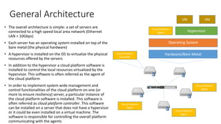
  • 5. General Architecture • The overall architecture is simple: a set of servers are connected to a high speed local area network (Ethernet LAN > 10Gbps) • Each server has an operating system installed on top of the bare metal (the physical hardware) • A hypervisor is installed on the OS to virtualize the physical resources offered by the servers • In addition to the hypervisor a cloud platform software is installed to control the local resources virtualized by the hypervisor. This software is often referred as the agent of the cloud platform • In order to implement system wide management and control functionalities of the cloud platform on one (or more to ensure resiliency) server, a particular instance of the cloud platform software is installed. This software is often referred as cloud platform controller. This software can be installed on a server that does not have a hypervisor or it could be even installed on a virtual machine. The software is responsible for controlling the overall platform communicating with the agents Hardware/Bare Metal Operating System Hypervisor Cloud Platform Agent VM VM Cloud Platform Controller Cloud Platform Agent Cloud Platform Agent Cloud Platform Agent
  • 6. Cloud Platform Implementations • Different public or private cloud platform implementation are available today: some of them are commercial other are open-source • Currently, we do not have a standard for the architecture of cloud platforms, however, their architecture is very similar, so taking a look at the architecture of one is sufficient to understand the other implementations • Public cloud internals (e.g. Google cloud, Microsoft Azure, Amazon AWS) are hidden, however, they have a similar architecture to the one available on the market • In this course we take a look at the architecture and functionalities of one cloud platform: OpenStack
  • 7. OpenStack • OpenStack is a free open-source software platform for IaaS cloud computing • Started as a joint project of Rackspace Hosting and of NASA in 2010 • Openstack today is supported and managed by the OpenStack Foundation, which composed by more than 500 companies (e.g. VMware, CISCO, Citrix, Oracle, Ericsson, IBM, etc) • It is the main solution adopted for private cloud computing
  • 8. OpenStack @ CERN OpenStack is widely adopted today by companies to build large public/private cloud deployments. Other User Stories: https://www.openstack.org/user-stories/
  • 9. OpenStack Software Platform • OpenStack runs on top of commodity server (no particular hardware is required) • The software platform is installed on each server and runs on top of the host operating system. • The platform can run only on the Linux OS, while it supports multiple hypervisor technologies • Through each hypervisor, OpenStack creates/destroys the VMs • Every server that has installed the OpenStack software (or a part of it) is called OpenStack Node • The platform manages the connection of VMs to Virtual Networks, which can be used to communicate with other VMs or with external networks • In addition to Virtual Machines and Virtual Networks, the platform manages the Storage. This enable the creation of virtual hard drives that can be connected to virtual machines Hardware Linux Operating System VM1 VM2 VM3 Hypervisor OpenStack Virtual Network
  • 10. OpenStack Instance • Nodes running the OpenStack software are configured to form a single OpenStack instance combining together computing, memory and storage capabilities to create VMs • In a single instance, at least one node is configured as controller which is in charge of coordinating OpenStack functions and managing the resources available to the instance • Other nodes are configured as compute nodes that offer computation and storage resources to run virtual machines • Nodes are connected through a (real) high speed local area network, which is used as • infrastructure on top of which the Virtual Networks are created • communication network used by the OpenStack components to communicate for coordination and management Linux Operating System Management and Coordination Services Openstack Controller VM1 VM2 Openstack Compute VM1 VM2 Openstack Compute Real LAN
  • 11. OpenStack Architecture • The platform exposes a web dashboard to allow users and administrators to manage virtual resources, i.e. VMs, Virtual Networks and Virtual Hard Drives • An interface based on REST APIs is also offered as machine- friendly interface • Such APIs can be used by external programs • A command line interface is also offered
  • 12. OpenStack Architecture • The OpenStack software is highly modular: • The functionalities of the platform are grouped into services: e.g. the compute service to manage the creation of VMs, the network service to manage the creation of Virtual Networks, the storage service to manage the creation of virtual hard drives • Each service is implemented as a different and separated module • Each module could work separately from the platform and it is developed and maintained as a separate project • Each service exposes a set of REST APIs, through this interface it can receive requests from platforms users and administrator via the web/command line interface and from other service modules • Coordination operations and status information among services, instead, are exchange using a message queue system
  • 13. OpenStack Services • Apart from Core Services, which are mandatory on each installation, other services are marked as optional, so they can be installed only if the functionalities they provide are needed in a specific OpenStack instance Mandatory Services Optional Services
  • 14. OpenStack Services • Services are installed on the controller node or in the compute nodes according to their functionalities • Some services are required to be installed on both controller and compute nodes with different configurations, since they implement different functionalities • All the services in the controller node leverage some supporting services, one Database (e.g. MySQL) for status and configuration storage and one Message Broker (e.g. Rabbit MQ) for message exchange across different modules
  • 15. Information Exchange/Communication • Inside the platform, services (and sub- services) interact each other in three different ways (there is no standard convention): • Message broker: they exchange a direct message via the message broker • REST API: a service invoke the REST API interface in the same manner performed by an external program • DataBase: two modules exchange information via the database, request/response is performed via TCP/IP connection • Since every information exchange is performed eventually via network, the allocation for the services is only suggested, for instance all the services that should be run on the controller could be spread out across different nodes in order to implement some load balancing policy
  • 16. Keystone • Keystone is the identity management component • Keystone is used by OpenStack for authentication and high-level authorization • It ensures security by granting/denying access to objects (e.g. Virtual Machines or Virtual Networks) to different Users • Objects are grouped into projects, authorizations can be granted per project that is assigned to a user • Keystone is usually installed on the Controller node Access Granted Access Denied
  • 17. Keystone • Keystone implements a token-based authorization • A user first interacts with keystone using an user/pass based authentication • If successful a token is received • The token is used to access all OpenStack services • Each service takes care of validating the token
  • 18. Nova • Nova is the VM management component, i.e. the compute service • It is responsible for the instantiation and management of Virtual Machines • Nova does not implement a new virtualization technology, but it interfaces with existing hypervisors to manage VMs • Different virtualization technologies can be used, from open-source technologies (e.g. KVM, Xen) to commercial (e.g. Wmware ESX) • It includes two different modules, the nova controller installed on the controller node and the nova agent installed on the compute nodes
  • 19. Nova –Subcomponents • The Nova module is installed on the controller node and on the compute node • On the controller node the nova component is responsible for handling the requests from the users and managing the resources available on the compute nodes. Specifically, it collects the requests of VM creation/destruction from the interface, it evaluates the corresponding actions to be performed and sends the commands to the compute node • On the compute node, the component is responsible for receiving instructions from the controller module and to translate it to the corresponding commands for the hypervisor
  • 20. Nova – Controller Subcomponents • The Nova module installed on the controller node is composed of the following sub-components • Nova-API: exposes the external REST interface used by users and other services • Nova-Conductor: manages all the control operations • Nova-Scheduler: evaluate the proper placement for a new VM according to the status of the compute nodes and the resource available • Nova-Network: implements basic networking services for VMs or interfaces with other network services if installed • Nova-Consoleauth and Nova-Novncproxy: implements a console service through which users can connect to VMs • All the components interact through the messaging queue
  • 21. Nova – Compute Subcomponents • On the compute node the Nova module is composed only of the compute service • The compute service receives commands from the controller (Conductor service) and instantiates/terminates VMs instances interacting with the hypervisor • Drivers for different hypervisors are maintained to interface the compute service to different hypervisors: • VMWare ESXi, a commercial hypervisor from VMWare • Xen, Libvirt, Qemu, Docker • Each driver exposes a common interface used by the nova-compute agent to interact with each hypervisor
  • 22. Nova – VM Creation Workflow • When a request for the creation of a new VM is issued by the user the nova components perform the following steps: 1. Nova-API receives the request that is forwarded to Nova-Conductor 2. Nova-Conductor forwards the request to Nova-Scheduler, which suggests the proper placement for the new VM (which compute node has available resources) 3. If the Nova-Scheduler allows the creation of the VM (sufficient resources are available in the system) Nova- Conductor forwards the request to the Nova-Network service to instantiate the proper network configuration 4. As the Network is properly configured, the request is forwarded to the Nova- Compute service of the node selected by Nova-Scheduler 5. The local Nova-Compute interacts with the hypervisor to create the VM
  • 23. Nova Scheduling Strategy and overcommitment • The scheduling policy can be customized to accommodate different requirements • The scheduler performs an initial filtering phase in which not suitable hosts are removed (they don’t have a specific characteristic like a passedthrough- device or they are out of resources), then an ordering of the hosts • The policy can be configured to include certain degree of over-commitment for RAM and CPU, i.e. more VCPU than the CPU available in a host are allocated (the CPU will go slower), more RAM than the one available in the system is allocated to VMs (the host will swap)
  • 24. Glance • Glance is the image management service • Each VM is instantiated from an image which includes a specific operating system pre-installed and pre-configured • Images can be customized, e.g. a web server image can have pre-installed a web server package • Glance manages the collection of VM templates • Glance subcomponents are: glance (for image management) and glance storage (for storage management) • Glance is responsible for exposing a REST API for managing the images (e.g. uploading an image, delete an image, etc) and store the list of the images available and its features on the DB • Glance storage, instead, is responsible for storing the images. It supports different storage options via different drivers, among them: • The local file system of the node on which the service is installed • A cloud file system, i.e. a distributed file system (a file system distributed among different hosts) or a cloud storage (we will cover them in details later on!)
  • 25. Neutron • Neutron is the network management components • VMs require a virtual network to communicate each other • Different Virtual Networks are instantiated for different VMs in order to ensure isolation among them, i.e. VMs created by different tenants cannot communicate • Neutron is the service responsible for managing the virtual network infrastructure, it allows the creation of Virtual Networks among VMs that can run on different Openstack compute nodes • The Local Physical Network that interconnects Computing nodes is exploited as infrastructure to enable the virtual networks across different compute nodes Linux Operating System VM1 VM2 Compute 1 VM3 VM4 Compute 2 Local Physical Network Virtual Networks
  • 26. Neutron • Neutron subcomponents are: neutron-server and neutron-agent • Neutron-Server: it is installed on the controller and it is responsible for managing the Virtual Networks by coordinating the neutron-agents running on the computing nodes. It is also responsible for exposing the REST APIs for the management of Virtual Networks to users • Neutron-Agent: it is responsible for managing the traffic to/from VMs running on the compute node on which it is installed. Specifically, it dispatches the traffic directed to/generated from the local VMs in order to emulates different virtual networks that span across different compute nodes. Data is dispatched on top of the local physical network. The agent must enforce isolation between different Virtual Networks Linux Operating System VM1 VM2 Compute 1 VM3 VM4 Compute 2 Neutron Server Controller Neutron Agent Neutron Agent Control data VN1 VN2
  • 27. Network Node • Virtual Networks are usually private networks • Neutron allows VMs to be connected to external networks, so VMs can connect to the Internet and vice-versa they can be accessible from the Internet • In order to connect Virtual Networks to the Internet, a Network Node must be instantiated • A Network Node is a node (usually the controller node) that is connected to an external network (towards the Internet) in addition to the local network that connects the OpenStack nodes • This node runs a particular agent, named Neutron- L3-Agent that is responsible for rerouting traffic from/to the private Virtual Networks to/from the public networks • This functionality is performed by instantiating Virtual Routers, which are responsible for implementing traffic routing and NAT functionalities • In addition to this, the Network Node also hosts a module named Neutron-DHCP-Agent, which is responsible for managing the network configuration assignment to VMs VM1 VM2 Compute 1 Neutron L3 Agent Network Node Public Network Neutron Agent Neutron DHCP Agent
  • 28. Neutron • Public IP addresses can be assigned to VMs • Virtual Routers at the edge of each Virtual Network will take care of implementing Network Address Translation • The platform allows to assign public IP addresses dynamically (floating IP address)
  • 29. Physical Network Infrastructure • A typical OpenStack network infrastructure connected to an external network is usually configured with three different physical networks: • A management network, exploited for OpenStack services communication • A VM internal network, exploited to dispatch the internal communication among different VMs • An external network for Internet access • The management network and the VM internal network can be implemented on the same physical LAN, i.e. OpenStack management traffic and internal VM traffic can be transmitted on the same LAN • Only one node, the Network Node, must be connected on the external network • The controller node can be connected only to the management network
  • 30. Neutron Agent • The Neutron Agent running on each compute node is highly configurable, different configurations are possible exploiting different technologies to process and forward traffic • One of the last version exploits OpenVSwitch to implement the local network functionalities to process and forward traffic between compute nodes and the network node • OpenVSwitch allows to rapidly reconfigure the behavior of each agent following the directives from the nova server
  • 31. OpenVSwitch • OpenVSwitch (OVS) is an open-source implementation of a distributed network virtual switch • It is specifically designed to provide a switching stack for hardware virtualization environments, it can run directly within (or jointly with) the hypervisor to manage the traffic to/from VMs • It supports the implementation of packet filtering, routing, switching and manipulation functionalities • OVS adopts a centralized approach (SDN): every node has its own OVS instance, which is controlled by a controller • Following the directives of the controller, all the OVS instances implements a distributed virtual switch
  • 32. Software Defined Networking (SDN) • OVS adopt the SDN paradigm: network rules are configured dynamically on each instance based on the directives coming from a centralized controller • Each OVS node has a table (the flow table) that describes the features of any incoming packet (e.g. the source IP, the destination MAC address, etc.) and the corresponding action to be executed (e.g. forward the packet, modify the packet, etc.) • Whenever a packet is received, the table is accessed, if the packet has a match with one of the entry in the table the corresponding action is executed • If no match is found, OVS sends a query message to the controller, which replies with a new rule to be added in the local table or a specific action to be performed once • The protocol that implements the communication between OVS instances and the controller is named OpenFlow
  • 33. VM – OVS communication • Each VM has a Virtual NIC, whose hardware is emulated by the hypervisor • In order to connect with the OVS instance of the computing node, the vNIC is linked to another virtual NIC created in the host operating system, e.g. tap0, tap1 • A tap is a virtual network interface that can be linked with a software, the hypervisor in this case, to receive/send network traffic (layer 2 data frames) to from the software • The tap is used to receive/send data traffic from/to the VM • Traffic from tap interfaces of from the physical interfaces is managed by OVS to implement routing and forwarding functionalities vNIC vNIC
  • 34. Network Node • OVS instances can be programmed by the Neutron Server to dispatch the data across different VMs running on the same compute node or on different compute nodes • When the data is directed towards an external network, instead, it is dispatched to the network node • In order to implement L3 routing functionalities and data dispatching, an OVS instance is also installed on the network node • Through the OVS instance running on the network node, L3 virtual routing functionalities are implemented to route traffic to/from the external network and the VMs (or in general the local Virtual Netowrks)
  • 35. Network Virtualization • Network Virtualization is the process through which Virtual Networks (VNs) for VMs are created on top of the same physical infrastructure • VNs are Layer2 networks, specifically Ethernet networks • The implementation of a Virtual Network requires the following: • Layer 2 data forwarding between VMs belonging to the same VN • Isolation between VNs, i.e. two VMs belonging to different VNs cannot communicate, unless there is a router connecting at Layer 3 the two VNs • In OpenStack, Network Virtualization requires that traffic is forwarded across different compute nodes and to/from the network node according to VN existence, i.e. if two compute nodes host two VMs belonging to the same VN the network service should be configured to forward traffic between them • To this aim each packet should be marked with the ID of the VN to which it belongs so it can be properly dispatched • Different existing network technologies are adopted: packet tagging or tunneling
  • 36. Virtual LAN • VLAN is one of the most widely adopted for network virtualization • The IEEE 802.1Q Ethernet networking standard was defined specifically to allow the creation of Virtual LANs on top of a regular Ethernet network • To this aim, the standard adds a new field on the Ethernet header, the VLAN ID (VID), that specifies the ID of the Virtual LAN to which it belongs • A switch (virtual of physical) that supports IEEE 802.1Q is responsible for adding the VID field when a packet is injected in the network, for removing it when it reaches destination and for delivering it according to the VID • For instance, broadcast frames must be delivered only to hosts belonging to the same VID, to guarantee isolation
  • 37. Neutron VLAN Operations • Neutron can be configured to use VLAN to create VNs • When a VN is created to connect two or more VMs, a VID is assigned to the VN by the Nova- Server • The latter configures the OVS of the compute nodes involved consequently, in order to tag traffic coming from a VM with the VID assigned to its VN and to forward packets to all compute nodes involved • When a packet is received by a compute node, the VID is removed and the packet is forwarded to all the VMs involved • In case the VN is connected to the Internet via a Virtual Router, the Neutron-Server configures also the OVS running on the Network Node to tag the packets coming from/directed to the Router assigned to the VN OVS OVS
  • 38. GRE Tunneling • Another virtualization mechanisms adopted is packet tunneling via GRE protocol • Generic Routing Encapsulation (GRE) is a tunneling protocol that allows to encapsulate network IP packets inside another IP packet • The protocol is used to create a tunnel between two internet hosts • The protocol adds an additional GRE header to specify the type of the encapsulated protocol • GRE can be used as mechanism to create Virtual Networks: a GRE tunnel is created for each pair of compute nodes (and between the compute node and the network node) that runs VMs belonging to a specific virtual network • Different GRE tunnel IDs are used for each Virtual Network
  • 39. Neutron GRE Operations • GRE can be used to create VNs • For each VN a GRE ID is instantiated by the Nova Server • The latter instructs the OVS instances to create a virtual network adapter (gre-1) on top of the physical interface • The GRE interface is responsible for creating the tunnel across the involved computing nodes (nodes that have at least one VM that belongs to the VN, or computing nodes and the Network Server) and encapsulate/decapsulate the traffic
  • 40. VXLAN • VLAN has a limit, VLAN identifiers are 12 bits long, consequently the maximum number of VLANs is set to 4094 • In large cloud implementations this number, even if high, can be an issue • Virtual Extensible LAN (VXLAN) is a network virtualization technology that attempts to address the scalability problems associated with large cloud computing deployments in order to remove this limit • With VXLAN you can have up to 16 millions of different VNs • VXLAN is still a packet encapsulation methodology between two endpoints, called virtual tunnel endpoints (VTE) in this case • Frames are encapsulated within UDP packets, while at the IP level the source and destination of the VTEs are specified • A VXLAN header is included to report the ID of the virtual LAN as two VTEs can support multiple VLANs at the same time
  • 41. Neutron VXLAN Operations • VXLAN tunnels are exploited by neutron in the same manner GRE tunnels are exploited • For each VN a new VXLAN ID is instantiated by the Nova Server • The latter instructs the OVS instances to encapsulate packets into VXLANs tunnels according to the VNs instantiation
  • 42. Cinder • Cinder is the component responsible for managing volumes • Each VM has a default virtual hard drive which stores the operating system • If a VM requires extra storage additional volumes can be dynamically created and attached to an instance • Such volumes are seen as virtual hard drives by the VM • Eventually, a virtual hard drive is stored in the file system as an image (a file or an object) • Cinder is responsible for managing those images and exposing them to the VMs • A virtual hard drive is exposed by the hypervisor, which accesses the actual virtual hard drive via the iSCSI protocol • iSCSI is an Internet Protocol based storage networking standard which provide block-level access to the storage • Cinder stores the volume images in the local file system of the node on which the service is installed or in a cloud file system We will cover cloud storage later in details!
  • 43. Cinder - Architecture • Cinder comprises the following components: • Cinder-Api, which exposes a rest interface to clients to control cinder operations (e.g. Nova or directly the final user) • Cinder-Volume, which is responsible for handling directly the requests from the the rest interface • Cinder-Scheduler, which is responsible for selecting the proper storage to store new drives (if multiple storages are configured on the system) • Cinder-Backup, which is responsible for creating backup of existing volumes when requested by the users
  • 44. Ceilometer • Ceilometer is the telemetry component • It monitors all the component of the instance, measuring the resource being used by each User • Data collected by Ceilometer can be used for billing purposes • Ceilometer also collects telemetry statistics which can be used to check the status of the system
  • 45. Ceilometer - Architecture • Ceilometer has a centralized Ceilometer-Collector that is responsible for receiving all the data from all the OpenStack components and store them into a DB (usually a NoSQL DB like Mongo DB) • In order to collect data from all the compute node, a Ceilometer-Agent is installed on each node. The agent is responsible for collecting all the notifications from all the local components and forward them to the collector • Eventually the collector exposes a set of REST APIs to retrieve the data from the database
  • 46. Horizon • OpenStack functionalities are exposed to Users though a web interface • The dashboard is usually exposed by the controller • It allows management of all the instances aspects • A set of command line tools are also included for backend management
  • 47. Service APIs • Every OpenStack service exposes a set of APIs • All APIs communication is REST • APIs are exposed by each service for inter-service interaction and to expose a set of functionalities to Users • APIs can be exploited by Users to embed automation process in external applications Documentation: http://developer.openstack.org/api-ref.html
  • 48. Swift • Swift is the object storage service available in OpenStack • It allows users and other OpenStack modules to store data (represented as objects) in the cloud platform • Other services, like for instance Cinder or Glance, can use Swift to store Volumes backups or images, respectively • The component is responsible for handling all the aspect of data storage, from receiving and storing the data to retrieving it • Data is usually eventually stored in a cloud storage, to guarantee scalability (even though local storage in the server where the service is installed is allowed) • Swift is composed of two components: • Swift-Proxy, which is responsible to expose the REST interface and handle request (to store a new object or to retrieve an object) • Swift-Storage-Node, which is installed on each Storage Node (a node that hosts some of the data) to actually store the data on a physical drive Intro ONLY, we will cover cloud storage later in details!
  • 49. Heat • Heat is the OpenStack orchestrator • It can manage VMs creation/destruction or their settings automatically • This automation is based on a set of rules that specify when certain conditions to trigger actions on the VM • Through heat, for instance, an autoscaling service can be created that exploit the status data from ceilometer to create/destroy VMs according to the status of the system • The component is composed of the following modules: • Heat-API that exposes the interface for the users to configure the orchestrator • Heat-Engine that is responsible for handling user request and implementing them
  • 51. High Availability (HA) • The current architecture includes only one instance of the managing components • OpenStack can be installed in the so-called high availability configuration, i.e. multiple instances of each service can be deployed in order to ensure high availability and resiliency • This can be performed in a similar manner cloud applications are deployed in a redundant manner to ensure high availability • In the high availability configuration, multiple instances of controller nodes are deployed with all the corresponding services to control the same set of computing nodes
  • 52. HA with dedicated node • Overall OpenStack APIs are exposed not directly by the controller node but through a HA proxy • The HA proxy is responsible for receiving the requests and dispatch them to one of the controller nodes • The proxy must implement functionalities to detect when Controller node failures occur to remove failing controller node to the list of active nodes • The State storage must be replicated across the controller nodes
  • 53. HA with simple redundancy • Overall OpenStack APIs are exposed directly by one controller, selected as master controller • The functionalities of the HA proxy are implemented on all the controller, one of them is marked as active and serves requests, while the others are marked as inactive • The HA proxy instances must coordinate to detect failures and trigger reconfiguration when needed • Again, the State storage must be replicated across the controller nodes