SlideShare a Scribd company logo
DETECTION OF FAULT LOCATION IN UNDERGROUND CABLE USING
ARDUINO
Flow of Presentation
• Introduction to Project
• Underground cable v/s Overhead cables
• Faults in underground cables
• Methods for the Detection of faults
• Introduction to the Circuit
• Working of the Circuit
• Different circuit components
Introduction
• The objective of this project is to determine the distance of
underground cable fault from base station in kilometers using an
Arduino board.
• Many time faults occur due to construction works and other reasons.
• Cables have some resistance. We are mainly focusing that resistance.
Resistance can vary with respect to the length of the cable.
• If the length of the cable is increase, the value of the resistance will also
increase.
• If any deviation occurs in the resistance value, we will call that is fault point
and finding that place through Arduino technology.
• That fault point represents the standard of distance (kilometre) from the
base station.This value displayed by display unit.
• Before attempting to locate underground cable faults on cable, it is
necessary to know where the cable is located and what route it takes. If the
fault is on secondary cable, knowing the exact route is even more critical.
• Since it is extremely difficult to find a cable fault without knowing
where the cable is, it makes sense to master cable locating and
tracing and to do a cable trace before beginning the fault locating
process.
• Success in locating or tracing the route of electrical cable and metal
pipe depends upon knowledge, skill, and perhaps, most of all,
experience.
• Although locating can be a complex job, it will very likely become
even more complex as more and more underground plant is installed.
It is just as important to understand how the equipment works as it is
to be thoroughly familiar with the exact equipment being used.
UNDER
GROUND
CABLES
Suitable for congested urban
areas where overhead lines may
be difficult or impossible to
install
Low maintenance
Required
Small voltage drops
Fewer faults
Not susceptible to shaking and
shorting due to vibrations, wind,
accidents, etc.
No interference with
communication system
Posses no danger to
wildlife or low flying
aircraft
It is more Expensive
Fault point cannot
be easily located
Can not be easily
Repaired
It can work only upto
66 kv due to insulation
difficulties
Erection cost of high voltage
cable is very high
Faults in Underground cables
• When there is a break in the
conductor of a cable, it is
called open circuit fault.
• The open-circuit fault can
check by a megger.
• The megger will indicate zero
resistance in the circuit of the
conductor that is not broken.
• However if a conductor is
broken the megger will
indicate an infinite resistance
Open circuit Fault Earth FaultShort circuit Fault
• When two conductors of a
multi core cable come in
critical contact with each
other due to insulation
failure, it is so called as short
circuit fault.
• The two terminals of a
megger are connected to any
two conductors.
• If the megger gives a zero
reading it indicates short-
circuit fault between these
conductors.
• When the conductor of a cable
comes in contact with earth
• To identify this fault, one terminal
of the megger is connected to the
conductor and the other terminal
connected to the earth.
• The megger indicates zero
reading; it means the conductor
is earthed.
Methods for the Detection of Faults
• Online method uses and
process the sampled
current and voltages to
determine the fault
points.
Online Method Off-Line Method
• This method uses a special instrument to test
out service of cable in the field. Offline method
is classified into two methods such as tracer
method and terminal method.
Terminal Methods Tracer Method
• Terminal method is used to detect the location of
the fault in a cable from one end or both the
ends without tracking. This method is used to
find general areas of the fault to accelerate
tracking on buried cable.
• In this method fault of the cable can be
detected by walking on the cable lines.
Fault location is denoted from
electromagnetic signal or audible signal.
This method is used to find the fault
location very accurately.
Time domain reflectometry (TDR):
• The TDR sends a low-energy signal through the cable, causing no insulation degradation.
A theoretically perfect cable returns that signal in a known time and in a known profile.
• Impedance variations in a “real-world” cable alter both the time and profile, which the
TDR screen or printout graphically represents.
• One weakness of TDR is that it does not pinpoint faults. TDR is accurate to within about
1% of testing range.
Detection of fault location in underground cable using arduino
Spark-induced Electromagnetic Signals
• During a voltage break-down in a conductor of length l, a spark-induced
electromagnetic signal is generated exactly where the break-down takes place.
• Two waves will propagate in both directions with a constant signal propagation
velocity, denoted v, towards the direction of the extremities of the conductor
(denoted A and B).
• The time difference ∆t measured between the two signals arriving at the
extremities of the conductor allows calculating the distance lf of the fault from
the extremity A by the simple relation,
Terminal Methods
1) Blavier Test (For a Single Cable Faults):
• When a ground fault occurs in a single cable and there is no other cables (without
faulty one), then blavier test can be performed to locate the fault in a single cable.
• Suppose-
• Fault to ground resistance = r
• Resistance from the Far end to the
cable fault = r2
• Resistance from the testing end of
the cable to the fault = r1
• First of all, We will insulate the far end of the cable to determine the
resistance between line to ground,
which is ;
𝑅1 = 𝑟1 + r
• Now, we will ground or earth the far end of the cable to find the
resistance between line to ground again.
𝑅2 = 𝑟1 +
𝑟 × 𝑟2
𝑟 + 𝑟2
• But the total resistance (before occurring the fault) was
R = 𝑟1 + 𝑟2
• Solving the above equations for r2 (fault location or distance), we get
𝑥 = 𝑅2 − (𝑅1 − 𝑅2)(𝑅 − 𝑅2)
2) Murray Loop Test:
• Wheatstone bridge’s principle is used in murray loop test to find the cable faults.
• The Wheatstone bridge is kept in balance by adjusting resistance of the ratio
arms Ra and Rb until the galvanometer deflection is zero.
Tracer Method
• In this method fault of the cable can be detected by walking on the cable lines.
Fault location is denoted from electromagnetic signal or audible signal. This
method is used to find the fault location very accurately.
• Transmitter create electromagnetic signals
on metallic conductors by producing output current.
• This electromagnetic field radiates from
the line is sense by receiver and we can
find exact location of fault as well as
depth of the cable.
• Cable locating test sets, often referred to as cable tracers, may be
grouped as follows:
i. Low frequency — usually less than 20 kHz sometimes referred to as
audio frequency (AF).
ii. High frequency — usually higher than 20 kHz and in the radio
frequency (RF) range to about 80 kHz.
iii. 60 Hz — most tracers provide this mode to allowtracing of
energized cables.
• Low frequency (AF) is considered the general-purpose selection
because it is more effective in tracing the route of cables located in
congested areas due to less capacitive coupling to everything else in
the ground. Low frequency can be more effective over greater
distances due to less capacitive leakage and because higher signal
power is allowed
Detection of fault location in underground cable using arduino
Introduction to circuit Diagram
• While a fault occurs for some reason, at that time the repairing process related to that
particular cable is difficult due to not knowing the exact location of the cable fault. The
proposed system is to find the exact location of the fault.
• This project uses Ohms Law concept, when a low voltage DC is applied to the feeder end
through a series resistor, then the current would differ based on the location of fault
occurred in the cable.
• In case is there any short circuit occurred from line to ground, then the voltage across
series resistor alters accordingly, then it is fed to an analog to digital converter to develop
exact data, which the pre programmed Arduino module will display in kilometres.
• The proposed system is designed with a set of resistors to signifying the length of a cable
in kilometers, and the fault creation is designed with a set of switches at every known
kilometer (KM) to cross check the exactness of the same. The fault happening at a specific
distance and the particular phase is displayed on an LCD interfaced to the 8051
microcontroller.
Block Diagram of Circuit
Detection of fault location in underground cable using arduino
Circuit Diagram
Working of Circuit
• The project uses a set of resistances in series i.e. R10,R11,R12,R13 and
R14,R15,R16,R17, & R18,R19,R20,R21, as shown in the circuit diagram, one set for each
phase.
• Each series resistors represents the resistance of the underground cable for a specific
distance thus 4 such resistances in series represent 1-4kms.
• 3 relays are used to common point of their contacts are grounded while the NO points
are connected to the input of the R10, R14 & R18 being the 3 phase cable input.
• Fault creation is made by a set of switches at every known KM to cross check the
accuracy of the same.
• The fault occurring at a particular distance and the respective phase is displayed on a
LCD interfaced to the Arduino board.
Circuit Components
1) RELAY :
• A relay is an electrically operated switch.
• Current flowing through the coil of the relay creates a magnetic field
which attracts a lever and changes the switch contacts.
• The coil current can be on or off so relays have two switch positions
and have double throw (changeover) switch contacts as shown in the
diagram.
• Relays allow one circuit to switch a second circuit which can be
completely separate from the first.
• For example a low voltage battery circuit can use a relay to switch a
230V AC mains circuit.
• There is no electrical connection inside the relay between the two
circuits, the link is magnetic and mechanical.
• To drive relay through MC ULN2003
relay driver IC is used
2) Relay driver ULN2003A
• The ULN2003 is a monolithic high voltage and high current Darlington
transistor arrays.
• It consists of seven NPN Darlington pairs that features high-voltage outputs
with common-cathode clamp diode for switching inductive loads.
• The collector-current rating of a single Darlington pair is 500mA.
• The Darlington pairs may be paralleled for higher current capability.
• The ULN2003A functions as an inverter.
• If the logic at input 1B is high then the output at its corresponding pin
1C will be low.
START
Initialize the LCD display pins
2,3,4,5,11,12
Define variable
Distance=input voltage
If input voltage
>=890 and <920
12
Yes
No
1
Output
Distance=8
2
If input
voltage
>=850 and
<890
Output
Distance=6
Output
Distance=4
If input
voltage
>=750 and
<850
Yes
No
Yes
3
No
Display
“Distance=6”
Display
“Distance=8”
Display
“Distance=4”
3
If input
voltage
>=600 and
<750
Output
Distance=2
Yes
Output
Distance=0
No
END
Display
“Distance=0”
Display
“Distance=2”
Arduino Code
// include the library code:
#include <LiquidCrystal.h>
// initialize the library with the numbers of the interface pins
LiquidCrystal lcd(12, 11, 5, 4, 3, 2);
// define phase control pins
int phase[3] = {7, 8, 9};
//********************************************************
*
int distance(int inputVoltage) {
if (inputVoltage >= 890 && inputVoltage < 920) {
return 8;
}
else if (inputVoltage >= 850 && inputVoltage < 890) {
return 6;
}
else if (inputVoltage >= 750 && inputVoltage < 850) {
return 4;
}
else if (inputVoltage >= 600 && inputVoltage < 750) {
return 2;
}
else return 0 ;
}
//*****************************************************
****
void setup() {
// set up the LCD's number of columns and rows:
lcd.begin(16, 2);
// set pin mode for phase relays
for (int j = 0; j < 3; j++) {
pinMode(phase[j], OUTPUT);
}
}
void loop() {
digitalWrite(phase[0], HIGH);
delay(1000);
int dist1 = distance(analogRead(A0));
if (dist1 == 0) {
lcd.setCursor(0, 0);
lcd.write("R: ");
lcd.setCursor(3, 0);
lcd.write("NF ");
}
else {
lcd.setCursor(0, 0);
lcd.write("R: ");
lcd.setCursor(3, 0);
lcd.print(dist1);
lcd.setCursor(4, 0);
lcd.write(" KM");
}
digitalWrite(phase[0], LOW);
//===============================================
=
digitalWrite(phase[1], HIGH);
delay(1000);
int dist2 = distance(analogRead(A0));
if (dist2 == 0) {
lcd.setCursor(8, 0);
lcd.write("Y: ");
lcd.setCursor(11, 0);
lcd.write("NF ");
}
else {
lcd.setCursor(8, 0);
lcd.write("Y: ");
lcd.setCursor(11, 0);
lcd.print(dist2);
lcd.setCursor(12, 0);
lcd.write(" KM");
}
digitalWrite(phase[1], LOW);
//==================================================
digitalWrite(phase[2], HIGH);
delay(1000);
int dist3 = distance(analogRead(A0));
if (dist3 == 0) {
lcd.setCursor(0, 1);
lcd.write("B: ");
lcd.setCursor(3, 1);
lcd.write("NF ");
}
else {
lcd.setCursor(0, 1);
lcd.write("B: ");
lcd.setCursor(3, 1);
lcd.print(dist3);
lcd.setCursor(4, 1);
lcd.write(" KM");
}
digitalWrite(phase[2], LOW);
}
References
• http://www.edgefxkits.com
• https://www.elprocus.com
• http://electrical-engineering-portal.com
• http://ieeexplore.ieee.org
• http://www.electrical4u.com
Detection of fault location in underground cable using arduino

More Related Content

What's hot (20)

PDF
UNDERGROUND CABLE FAULT DISTANCE LOCATOR
ijiert bestjournal
 
PPTX
PPT ON 33/11KV SUBSTATION
Ravi Phadtare
 
PPTX
Fault detection using iot PRESENTATION
AnjanKumarHanumantha
 
PPTX
Inverter
Vinod Srivastava
 
PPTX
concept of resilience and self healing in smart grid
Kundan Kumar
 
PPTX
Powergrid Corporation India Limited industrial training
Akriti Gupta
 
DOCX
smart grid seminar report
ramesh kumawat
 
PPTX
Differential Protection Relay
kishore kish
 
PPS
electrical distribution system ppt/13b61a0221
saikrishna kandhikatla
 
PPTX
Power theft detection
Aravind Shaji
 
PPT
Instrument transformer CT & PT
Chandan Singh
 
PDF
33-11-kv-substation-training-report (1) (1).pdf
SagarRana91
 
PPTX
132kV GSS ppt
Abhishek Dosaya
 
PPTX
Pulse width modulation (PWM)
amar pandey
 
PPTX
Electric power system
vishalmahar3
 
PPTX
3 phase Transmission Line fault detector edit 1-3.pptx
Krishna2017
 
PPTX
Electric substation
ANNU KUMAR
 
PPTX
Artificial intelligence in power system
Bittu Goswami
 
DOCX
Report on industrial summer training on 220 kv substation
Ashutosh Srivastava
 
UNDERGROUND CABLE FAULT DISTANCE LOCATOR
ijiert bestjournal
 
PPT ON 33/11KV SUBSTATION
Ravi Phadtare
 
Fault detection using iot PRESENTATION
AnjanKumarHanumantha
 
concept of resilience and self healing in smart grid
Kundan Kumar
 
Powergrid Corporation India Limited industrial training
Akriti Gupta
 
smart grid seminar report
ramesh kumawat
 
Differential Protection Relay
kishore kish
 
electrical distribution system ppt/13b61a0221
saikrishna kandhikatla
 
Power theft detection
Aravind Shaji
 
Instrument transformer CT & PT
Chandan Singh
 
33-11-kv-substation-training-report (1) (1).pdf
SagarRana91
 
132kV GSS ppt
Abhishek Dosaya
 
Pulse width modulation (PWM)
amar pandey
 
Electric power system
vishalmahar3
 
3 phase Transmission Line fault detector edit 1-3.pptx
Krishna2017
 
Electric substation
ANNU KUMAR
 
Artificial intelligence in power system
Bittu Goswami
 
Report on industrial summer training on 220 kv substation
Ashutosh Srivastava
 

Similar to Detection of fault location in underground cable using arduino (20)

PDF
IRJET- Underground Cable Fault Distance Locator
IRJET Journal
 
PDF
Detection of Underground Cable Fault using Arduino
IRJET Journal
 
PDF
Analysis of Fault Detection and its Location using Microcontroller for Underg...
IRJET Journal
 
PDF
IRJET - Detection of Foible Point Locating System for Hypogen Transmission Lines
IRJET Journal
 
PDF
B1102030610
IOSR Journals
 
PDF
Arduino based-underground-cable-fault-detector
KANAIYABHATT
 
PDF
IOT BASED UNDER GROUND CABLE FAULT DETECTION AND LOCATOR
IRJET Journal
 
PDF
IRJET- Design of Arduino based Underground Cable Fault Detector
IRJET Journal
 
DOCX
Arduino based underground cable fault detection
Isa Rachman
 
PDF
IRJET- Cable Fault Detection using IoT
IRJET Journal
 
PPTX
UNDERGROUND CABLE FAULT DISTANCE DETECTOR
SaiDhanushM
 
DOCX
New project report
Sai Printers
 
PPTX
Underground Impedance cable Fault - PPT - 1.pptx
HODElectrical6
 
PDF
IRJET- Design and Development of Underground Cable Fault Detection and Locali...
IRJET Journal
 
PPTX
cable fault.pptx
ramalingams7
 
PPTX
newppt undergsjsoaosjfzyidulflround.pptx
her96334
 
PDF
IRJET- Arduino based Single Phase Fault Detection System using IoT
IRJET Journal
 
PDF
Power Cable Fault Location - Medium & High Voltage Cables
Thorne & Derrick International
 
PDF
Cable fault-finding-guide
vishal laddha
 
PDF
IRJET- Iot Based Underground Cable Line Fault Detection
IRJET Journal
 
IRJET- Underground Cable Fault Distance Locator
IRJET Journal
 
Detection of Underground Cable Fault using Arduino
IRJET Journal
 
Analysis of Fault Detection and its Location using Microcontroller for Underg...
IRJET Journal
 
IRJET - Detection of Foible Point Locating System for Hypogen Transmission Lines
IRJET Journal
 
B1102030610
IOSR Journals
 
Arduino based-underground-cable-fault-detector
KANAIYABHATT
 
IOT BASED UNDER GROUND CABLE FAULT DETECTION AND LOCATOR
IRJET Journal
 
IRJET- Design of Arduino based Underground Cable Fault Detector
IRJET Journal
 
Arduino based underground cable fault detection
Isa Rachman
 
IRJET- Cable Fault Detection using IoT
IRJET Journal
 
UNDERGROUND CABLE FAULT DISTANCE DETECTOR
SaiDhanushM
 
New project report
Sai Printers
 
Underground Impedance cable Fault - PPT - 1.pptx
HODElectrical6
 
IRJET- Design and Development of Underground Cable Fault Detection and Locali...
IRJET Journal
 
cable fault.pptx
ramalingams7
 
newppt undergsjsoaosjfzyidulflround.pptx
her96334
 
IRJET- Arduino based Single Phase Fault Detection System using IoT
IRJET Journal
 
Power Cable Fault Location - Medium & High Voltage Cables
Thorne & Derrick International
 
Cable fault-finding-guide
vishal laddha
 
IRJET- Iot Based Underground Cable Line Fault Detection
IRJET Journal
 
Ad

Recently uploaded (20)

PDF
Stokey: A Jewish Village by Rachel Kolsky
History of Stoke Newington
 
PPTX
Nitrogen rule, ring rule, mc lafferty.pptx
nbisen2001
 
PPTX
care of patient with elimination needs.pptx
Rekhanjali Gupta
 
PDF
Exploring the Different Types of Experimental Research
Thelma Villaflores
 
PPTX
Identifying elements in the story. Arrange the events in the story
geraldineamahido2
 
PPTX
DAY 1_QUARTER1 ENGLISH 5 WEEK- PRESENTATION.pptx
BanyMacalintal
 
PDF
Chapter-V-DED-Entrepreneurship: Institutions Facilitating Entrepreneurship
Dayanand Huded
 
PPTX
Controller Request and Response in Odoo18
Celine George
 
PDF
Council of Chalcedon Re-Examined
Smiling Lungs
 
PPTX
How to Manage Allocation Report for Manufacturing Orders in Odoo 18
Celine George
 
PDF
Is Assignment Help Legal in Australia_.pdf
thomas19williams83
 
PDF
Horarios de distribución de agua en julio
pegazohn1978
 
PPTX
EDUCATIONAL MEDIA/ TEACHING AUDIO VISUAL AIDS
Sonali Gupta
 
PPTX
Introduction to Indian Writing in English
Trushali Dodiya
 
PDF
Android Programming - Basics of Mobile App, App tools and Android Basics
Kavitha P.V
 
PPTX
ENGlish 8 lesson presentation PowerPoint.pptx
marawehsvinetshe
 
PPTX
Light Reflection and Refraction- Activities - Class X Science
SONU ACADEMY
 
PPTX
infertility, types,causes, impact, and management
Ritu480198
 
PPTX
How to Configure Re-Ordering From Portal in Odoo 18 Website
Celine George
 
PDF
Aprendendo Arquitetura Framework Salesforce - Dia 03
Mauricio Alexandre Silva
 
Stokey: A Jewish Village by Rachel Kolsky
History of Stoke Newington
 
Nitrogen rule, ring rule, mc lafferty.pptx
nbisen2001
 
care of patient with elimination needs.pptx
Rekhanjali Gupta
 
Exploring the Different Types of Experimental Research
Thelma Villaflores
 
Identifying elements in the story. Arrange the events in the story
geraldineamahido2
 
DAY 1_QUARTER1 ENGLISH 5 WEEK- PRESENTATION.pptx
BanyMacalintal
 
Chapter-V-DED-Entrepreneurship: Institutions Facilitating Entrepreneurship
Dayanand Huded
 
Controller Request and Response in Odoo18
Celine George
 
Council of Chalcedon Re-Examined
Smiling Lungs
 
How to Manage Allocation Report for Manufacturing Orders in Odoo 18
Celine George
 
Is Assignment Help Legal in Australia_.pdf
thomas19williams83
 
Horarios de distribución de agua en julio
pegazohn1978
 
EDUCATIONAL MEDIA/ TEACHING AUDIO VISUAL AIDS
Sonali Gupta
 
Introduction to Indian Writing in English
Trushali Dodiya
 
Android Programming - Basics of Mobile App, App tools and Android Basics
Kavitha P.V
 
ENGlish 8 lesson presentation PowerPoint.pptx
marawehsvinetshe
 
Light Reflection and Refraction- Activities - Class X Science
SONU ACADEMY
 
infertility, types,causes, impact, and management
Ritu480198
 
How to Configure Re-Ordering From Portal in Odoo 18 Website
Celine George
 
Aprendendo Arquitetura Framework Salesforce - Dia 03
Mauricio Alexandre Silva
 
Ad

Detection of fault location in underground cable using arduino

  • 1. DETECTION OF FAULT LOCATION IN UNDERGROUND CABLE USING ARDUINO
  • 2. Flow of Presentation • Introduction to Project • Underground cable v/s Overhead cables • Faults in underground cables • Methods for the Detection of faults • Introduction to the Circuit • Working of the Circuit • Different circuit components
  • 3. Introduction • The objective of this project is to determine the distance of underground cable fault from base station in kilometers using an Arduino board. • Many time faults occur due to construction works and other reasons. • Cables have some resistance. We are mainly focusing that resistance. Resistance can vary with respect to the length of the cable.
  • 4. • If the length of the cable is increase, the value of the resistance will also increase. • If any deviation occurs in the resistance value, we will call that is fault point and finding that place through Arduino technology. • That fault point represents the standard of distance (kilometre) from the base station.This value displayed by display unit. • Before attempting to locate underground cable faults on cable, it is necessary to know where the cable is located and what route it takes. If the fault is on secondary cable, knowing the exact route is even more critical.
  • 5. • Since it is extremely difficult to find a cable fault without knowing where the cable is, it makes sense to master cable locating and tracing and to do a cable trace before beginning the fault locating process. • Success in locating or tracing the route of electrical cable and metal pipe depends upon knowledge, skill, and perhaps, most of all, experience. • Although locating can be a complex job, it will very likely become even more complex as more and more underground plant is installed. It is just as important to understand how the equipment works as it is to be thoroughly familiar with the exact equipment being used.
  • 6. UNDER GROUND CABLES Suitable for congested urban areas where overhead lines may be difficult or impossible to install Low maintenance Required Small voltage drops Fewer faults Not susceptible to shaking and shorting due to vibrations, wind, accidents, etc. No interference with communication system Posses no danger to wildlife or low flying aircraft It is more Expensive Fault point cannot be easily located Can not be easily Repaired It can work only upto 66 kv due to insulation difficulties Erection cost of high voltage cable is very high
  • 7. Faults in Underground cables • When there is a break in the conductor of a cable, it is called open circuit fault. • The open-circuit fault can check by a megger. • The megger will indicate zero resistance in the circuit of the conductor that is not broken. • However if a conductor is broken the megger will indicate an infinite resistance Open circuit Fault Earth FaultShort circuit Fault • When two conductors of a multi core cable come in critical contact with each other due to insulation failure, it is so called as short circuit fault. • The two terminals of a megger are connected to any two conductors. • If the megger gives a zero reading it indicates short- circuit fault between these conductors. • When the conductor of a cable comes in contact with earth • To identify this fault, one terminal of the megger is connected to the conductor and the other terminal connected to the earth. • The megger indicates zero reading; it means the conductor is earthed.
  • 8. Methods for the Detection of Faults • Online method uses and process the sampled current and voltages to determine the fault points. Online Method Off-Line Method • This method uses a special instrument to test out service of cable in the field. Offline method is classified into two methods such as tracer method and terminal method. Terminal Methods Tracer Method • Terminal method is used to detect the location of the fault in a cable from one end or both the ends without tracking. This method is used to find general areas of the fault to accelerate tracking on buried cable. • In this method fault of the cable can be detected by walking on the cable lines. Fault location is denoted from electromagnetic signal or audible signal. This method is used to find the fault location very accurately.
  • 9. Time domain reflectometry (TDR): • The TDR sends a low-energy signal through the cable, causing no insulation degradation. A theoretically perfect cable returns that signal in a known time and in a known profile. • Impedance variations in a “real-world” cable alter both the time and profile, which the TDR screen or printout graphically represents. • One weakness of TDR is that it does not pinpoint faults. TDR is accurate to within about 1% of testing range.
  • 11. Spark-induced Electromagnetic Signals • During a voltage break-down in a conductor of length l, a spark-induced electromagnetic signal is generated exactly where the break-down takes place. • Two waves will propagate in both directions with a constant signal propagation velocity, denoted v, towards the direction of the extremities of the conductor (denoted A and B). • The time difference ∆t measured between the two signals arriving at the extremities of the conductor allows calculating the distance lf of the fault from the extremity A by the simple relation,
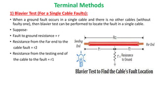
  • 12. Terminal Methods 1) Blavier Test (For a Single Cable Faults): • When a ground fault occurs in a single cable and there is no other cables (without faulty one), then blavier test can be performed to locate the fault in a single cable. • Suppose- • Fault to ground resistance = r • Resistance from the Far end to the cable fault = r2 • Resistance from the testing end of the cable to the fault = r1
  • 13. • First of all, We will insulate the far end of the cable to determine the resistance between line to ground, which is ; 𝑅1 = 𝑟1 + r • Now, we will ground or earth the far end of the cable to find the resistance between line to ground again. 𝑅2 = 𝑟1 + 𝑟 × 𝑟2 𝑟 + 𝑟2 • But the total resistance (before occurring the fault) was R = 𝑟1 + 𝑟2 • Solving the above equations for r2 (fault location or distance), we get 𝑥 = 𝑅2 − (𝑅1 − 𝑅2)(𝑅 − 𝑅2)
  • 14. 2) Murray Loop Test: • Wheatstone bridge’s principle is used in murray loop test to find the cable faults. • The Wheatstone bridge is kept in balance by adjusting resistance of the ratio arms Ra and Rb until the galvanometer deflection is zero.
  • 15. Tracer Method • In this method fault of the cable can be detected by walking on the cable lines. Fault location is denoted from electromagnetic signal or audible signal. This method is used to find the fault location very accurately. • Transmitter create electromagnetic signals on metallic conductors by producing output current. • This electromagnetic field radiates from the line is sense by receiver and we can find exact location of fault as well as depth of the cable.
  • 16. • Cable locating test sets, often referred to as cable tracers, may be grouped as follows: i. Low frequency — usually less than 20 kHz sometimes referred to as audio frequency (AF). ii. High frequency — usually higher than 20 kHz and in the radio frequency (RF) range to about 80 kHz. iii. 60 Hz — most tracers provide this mode to allowtracing of energized cables. • Low frequency (AF) is considered the general-purpose selection because it is more effective in tracing the route of cables located in congested areas due to less capacitive coupling to everything else in the ground. Low frequency can be more effective over greater distances due to less capacitive leakage and because higher signal power is allowed
  • 18. Introduction to circuit Diagram • While a fault occurs for some reason, at that time the repairing process related to that particular cable is difficult due to not knowing the exact location of the cable fault. The proposed system is to find the exact location of the fault. • This project uses Ohms Law concept, when a low voltage DC is applied to the feeder end through a series resistor, then the current would differ based on the location of fault occurred in the cable. • In case is there any short circuit occurred from line to ground, then the voltage across series resistor alters accordingly, then it is fed to an analog to digital converter to develop exact data, which the pre programmed Arduino module will display in kilometres. • The proposed system is designed with a set of resistors to signifying the length of a cable in kilometers, and the fault creation is designed with a set of switches at every known kilometer (KM) to cross check the exactness of the same. The fault happening at a specific distance and the particular phase is displayed on an LCD interfaced to the 8051 microcontroller.
  • 19. Block Diagram of Circuit
  • 22. Working of Circuit • The project uses a set of resistances in series i.e. R10,R11,R12,R13 and R14,R15,R16,R17, & R18,R19,R20,R21, as shown in the circuit diagram, one set for each phase. • Each series resistors represents the resistance of the underground cable for a specific distance thus 4 such resistances in series represent 1-4kms. • 3 relays are used to common point of their contacts are grounded while the NO points are connected to the input of the R10, R14 & R18 being the 3 phase cable input. • Fault creation is made by a set of switches at every known KM to cross check the accuracy of the same. • The fault occurring at a particular distance and the respective phase is displayed on a LCD interfaced to the Arduino board.
  • 23. Circuit Components 1) RELAY : • A relay is an electrically operated switch. • Current flowing through the coil of the relay creates a magnetic field which attracts a lever and changes the switch contacts. • The coil current can be on or off so relays have two switch positions and have double throw (changeover) switch contacts as shown in the diagram.
  • 24. • Relays allow one circuit to switch a second circuit which can be completely separate from the first. • For example a low voltage battery circuit can use a relay to switch a 230V AC mains circuit. • There is no electrical connection inside the relay between the two circuits, the link is magnetic and mechanical. • To drive relay through MC ULN2003 relay driver IC is used
  • 25. 2) Relay driver ULN2003A • The ULN2003 is a monolithic high voltage and high current Darlington transistor arrays. • It consists of seven NPN Darlington pairs that features high-voltage outputs with common-cathode clamp diode for switching inductive loads. • The collector-current rating of a single Darlington pair is 500mA. • The Darlington pairs may be paralleled for higher current capability.
  • 26. • The ULN2003A functions as an inverter. • If the logic at input 1B is high then the output at its corresponding pin 1C will be low.
  • 27. START Initialize the LCD display pins 2,3,4,5,11,12 Define variable Distance=input voltage If input voltage >=890 and <920 12 Yes No
  • 28. 1 Output Distance=8 2 If input voltage >=850 and <890 Output Distance=6 Output Distance=4 If input voltage >=750 and <850 Yes No Yes 3 No Display “Distance=6” Display “Distance=8” Display “Distance=4”
  • 30. Arduino Code // include the library code: #include <LiquidCrystal.h> // initialize the library with the numbers of the interface pins LiquidCrystal lcd(12, 11, 5, 4, 3, 2); // define phase control pins int phase[3] = {7, 8, 9}; //******************************************************** * int distance(int inputVoltage) { if (inputVoltage >= 890 && inputVoltage < 920) { return 8; } else if (inputVoltage >= 850 && inputVoltage < 890) { return 6; } else if (inputVoltage >= 750 && inputVoltage < 850) { return 4; } else if (inputVoltage >= 600 && inputVoltage < 750) { return 2; }
  • 31. else return 0 ; } //***************************************************** **** void setup() { // set up the LCD's number of columns and rows: lcd.begin(16, 2); // set pin mode for phase relays for (int j = 0; j < 3; j++) { pinMode(phase[j], OUTPUT); } } void loop() { digitalWrite(phase[0], HIGH); delay(1000); int dist1 = distance(analogRead(A0)); if (dist1 == 0) { lcd.setCursor(0, 0); lcd.write("R: "); lcd.setCursor(3, 0); lcd.write("NF "); } else { lcd.setCursor(0, 0); lcd.write("R: "); lcd.setCursor(3, 0); lcd.print(dist1); lcd.setCursor(4, 0); lcd.write(" KM"); } digitalWrite(phase[0], LOW); //=============================================== = digitalWrite(phase[1], HIGH); delay(1000); int dist2 = distance(analogRead(A0)); if (dist2 == 0) { lcd.setCursor(8, 0); lcd.write("Y: "); lcd.setCursor(11, 0); lcd.write("NF "); }
  • 32. else { lcd.setCursor(8, 0); lcd.write("Y: "); lcd.setCursor(11, 0); lcd.print(dist2); lcd.setCursor(12, 0); lcd.write(" KM"); } digitalWrite(phase[1], LOW); //================================================== digitalWrite(phase[2], HIGH); delay(1000); int dist3 = distance(analogRead(A0)); if (dist3 == 0) { lcd.setCursor(0, 1); lcd.write("B: "); lcd.setCursor(3, 1); lcd.write("NF "); } else { lcd.setCursor(0, 1); lcd.write("B: "); lcd.setCursor(3, 1); lcd.print(dist3); lcd.setCursor(4, 1); lcd.write(" KM"); } digitalWrite(phase[2], LOW); }
  • 33. References • http://www.edgefxkits.com • https://www.elprocus.com • http://electrical-engineering-portal.com • http://ieeexplore.ieee.org • http://www.electrical4u.com