


![DRAWBOT – A MINI CNC PLOTTER MAIN PROJECT
DEPARTMENT OF IT 33 LBSCEK
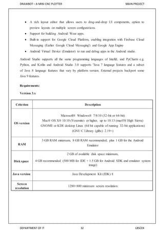
Version 2.x
Criterion Description
OS version
Windows 7 or later
Mac OS X 10.9.5 or later
GNOME or KDE desktop Linux
RAM 8 GB RAM recommended; plus 1 GB for the Android Emulator[20]
Disk space
500 MB disk space for Android Studio, at least 1.5 GB for Android SDK, emulator
system images, and caches
Java version Java Development Kit (JDK) 8
Screen
resolution 1280×800 minimum screen resolution.
Version 1.x
Criterion Description
OS version
Mac OS X 10.8.5 or later
GNOME, KDE or Unity desktop on Ubuntu or Fedora or GNU/Linux
Debian
RAM 3 GB RAM minimum, 4 GB RAM recommended
Disk space 500 MB disk space
Space for Android
SDK At least 1 GB for Android SDK, emulator system images, and caches
JDK version Java Development Kit (JDK) 7 or higher
Screen resolution 1280×800 minimum screen resolution](https://image.slidesharecdn.com/drawbotpart-3-180508044010/85/DrawBot-Android-Thing-CNC-Plotter-36-320.jpg)


More Related Content
What's hot (20)
Similar to DrawBot - Android Thing CNC Plotter (20)


Recently uploaded (20)


![[PyCon US 2025] Scaling the Mountain_ A Framework for Tackling Large-Scale Te...](https://cdn.slidesharecdn.com/ss_thumbnails/pyconus2025scalingthemountainaframeworkfortacklinglarge-scaletechdebt-250517122757-38c6df76-thumbnail.jpg?width=560&fit=bounds)


DrawBot - Android Thing CNC Plotter
- 1. DRAWBOT – A MINI CNC PLOTTER MAIN PROJECT DEPARTMENT OF IT iii LBSCEK TABLE OF CONTENTS CHAPTER 1................................................................................................................................ 1 INTRODUCTION........................................................................................................................ 1 1.2 Computer Numerical Control (CNC) ................................................................................ 1 1.2.1 Cartesian Coordinate System................................................................................... 2 1.3 DrawBot – A Mini CNC Plotter........................................................................................ 4 CHAPTER 2................................................................................................................................ 5 BLOCK DIAGRAM..................................................................................................................... 5 2.1 Description.................................................................................................................... 5 2.1.1 Android Things.......................................................................................................6 2.1.2 Arduino.................................................................................................................. 6 2.1.3 Motors................................................................................................................... 7 2.2 Working........................................................................................................................ 8 CHAPTER 3................................................................................................................................ 9 CIRCUIT DIAGRAM AND WORKING....................................................................................... 9 3.1 Description.................................................................................................................. 10 3.2 Circuit Components ..................................................................................................... 10 3.2.1 Android Thing (Picoi.MX7 Dual Development Board).............................................. 10 3.2.2 Arduino UNO........................................................................................................ 12 3.2.3 Breadboard (for Ground &VCC)............................................................................. 14 3.2.4 Motor Driver IC.................................................................................................... 15 3.2.5 Servo Motor......................................................................................................... 16 3.2.6 The LED status light.............................................................................................. 17 3.2.7 Stepper Motor...................................................................................................... 17 3.2.8 DVD/CD Drive....................................................................................................... 18 3.2.9 Connector............................................................................................................ 19 3.3 Working...................................................................................................................... 19 3.4 Design......................................................................................................................... 20 CHAPTER 4.............................................................................................................................. 23 SOFTWARE.............................................................................................................................. 23 4.1 G-code........................................................................................................................ 23 4.2 Inkscape.......................................................................................................................... 26 4.3 Android Program............................................................................................................... 27 4.3.1 Algorithm................................................................................................................... 27
- 2. DRAWBOT – A MINI CNC PLOTTER MAIN PROJECT DEPARTMENT OF IT iv LBSCEK 4.3.2 Flow Chart.................................................................................................................. 28 4.3.3 User Interface of Android Program........................................................................ 29 4.4 Android Studio............................................................................................................. 31 4.5 Arduino Program......................................................................................................... 34 4.5.1 Algorithm............................................................................................................. 34 4.5.3 Arduino IDE.......................................................................................................... 36 5.1 Advantages.................................................................................................................. 37 5.2 Disadvantages ............................................................................................................. 38 5.3 Applications................................................................................................................. 38 CHAPTER 6.............................................................................................................................. 40 CONCLUSION.......................................................................................................................... 40 6.1 Future Scope............................................................................................................... 40 REFERENCE............................................................................................................................. 41
- 3. DRAWBOT – A MINI CNC PLOTTER MAIN PROJECT DEPARTMENT OF IT v LBSCEK TABLE OF FIGURES Figure Title Page 1.1 Intersecting lines form right angles and establish the zero point (Allen- Bradley) 2 1.2 The three-dimensional coordinate planes (axes) used in CNC 2 1.3 The quadrants formed when the X and Y axes cross are used to accurately located 3 2.1 Block Diagram 5 3.1 Circuit Diagram 9 3.2 Pico i.MX7 Dual Development Board 10 3.3 Pin out Diagram 11 3.4 Arduino board 12 3.5 Arduino Pin out Diagram 13 3.6 Breadboard 14 3.7 L293D Motor Driver IC 15 3.8 L293D Pin out diagram 15 3.9 Servo Motor 16 3.10 28BYJ48 Stepper motor 18 3.11 DVD Drive 20 3.12 Pen setup 21 3.13 Final setup 22 4.1 Booting Screen 29 4.2 Android Program UI 29 4.3 GCode Selection 30 4.4 External Input Selection 30 4.5 Start Drawing Button Activity 31 5.1 Plotted output image 37
- 4. DRAWBOT – A MINI CNC PLOTTER MAIN PROJECT DEPARTMENT OF IT 1 LBSCEK CHAPTER 1 INTRODUCTION CNC stands for Computer Numeric Control and typically refers to a machine whose operation is controlled by a computer. The most common usage of CNC, and the one relevant to us, is the name given to devices that, under computer control are able to cut, etch, mill, engrave, build, turn and otherwise perform manufacturing operations on various materials. Typically, a CNC machine has the ability to move a cutting or 3D printing head in 2 to 6 axes, meaning that it can position that tool head at a precise point in or on the material to create the cut or operation desired at that point. By moving the head through multiple points, the cutting head can cut or sculpt the design represented by a data stream of positioning points being sent by the PC. By controlling a CNC machine through a PC it is possible for the user to design a product on-screen, convert it to CNC-reliable code and then send that data to the CNC machine for it to produce a physical copy of the item designed. 1.2 COMPUTER NUMERICALCONTROL(CNC) The term numerical control is a widely accepted and commonly used term in the machine tool industry. Numerical Control (NC) enables an operator to communicate with machine tools through a series of numbers and symbols. NC which quickly became Computer Numerical Control (CNC) has brought tremendous changes to the metal working industry. New machine tools in CNC have enabled industry. New machine tool is CNC have enabled industry to consistently produce parts to accuracies undreamed of only a few years ago. The same part can be reproduced to the same degree of accuracy any number of times if the CNC program has been properly prepared and the computer properly programmed. The operating commands which control the machine tool are executed automatically with amazing speed, accuracy, efficiency and repeatability. The ever-increasing use of CNC in industry has created a need for personnel who are knowledgeable about and capable of preparing the programs which guide the machine tools to produce parts to the required shape and accuracy.
- 5. DRAWBOT – A MINI CNC PLOTTER MAIN PROJECT DEPARTMENT OF IT 2 LBSCEK Fig 1.1: Intersecting lines form right angles and establish the zero point (Allen- Bradley) Fig 1.2: The three-dimensional coordinate planes (axes) used in CNC. 1.2.1 Cartesian Coordinate System Almost everything that can be produced on a conventional machine tool can be produced on a computer numerical control machine tool, with its many advantages. The machine tool
- 6. DRAWBOT – A MINI CNC PLOTTER MAIN PROJECT DEPARTMENT OF IT 3 LBSCEK movements used in producing a product are of two basic types: point to point (straight-line movements) and continuous path (contouring movements). The Cartesian, or rectangular, coordinate system was devised by the French mathematician and philosopher Rene’ Descartes. With this system, any specific point can be described in mathematical terms from any other point along three perpendicular axes. This concept fits machine tools perfectly since their construction is generally based on three axes of motion (X, Y, Z) plus an axis of rotation. On a plain vertical milling machine, the X axis is the horizontal movement (right or left) of the table, the Y axis is the table cross movement (toward or away from the column), and the Z axis is the vertical movement of the knee or the spindle. CNC systems rely heavily on the use of rectangular coordinates because the programmer can locate every point on a job precisely. Fig 1.3: The quadrants formed when the X and Y axes cross are used to accurately located The three-dimensional coordinate planes are shown in Fig. 1.2. The X and Y planes (axes) are horizontal and represent horizontal machine table motions. The Z plane or axis represents the vertical tool motion. The plus (+) and minus (-) signs indicate the direction from the zero point (origin) along the axis of movement. The four quadrants formed when the XY axes cross are numbered in a counterclockwise direction (Fig. 1.3). All positions located in quadrant 1 would be positive (X+) and positive (Y+). In the second quadrant, all positions would be negative X (X-) and positive (Y+). In the third quadrant, all locations would be
- 7. DRAWBOT – A MINI CNC PLOTTER MAIN PROJECT DEPARTMENT OF IT 4 LBSCEK negative X (X-) and negative (Y-). In the fourth quadrant, all locations would be positive X (X+) and negative Y (Y-). In Fig. 1.3, point A would be 2 units to the right of the Y axis and 2 units Fig 1.3: The quadrants formed when the X and Y axes cross are used to accurately located above the X axis. Assume that each unit equals 1.000. The location of point A would be X + 2.000 and Y + 2.000. For point B, the location would be X + 1.000 and Y - 2.000. In CNC programming it is not necessary to indicate plus (+) values since these are assumed. However, the minus (-) values must be indicated. For example, the locations of both A and B would be indicated as follows: A X2.000 Y2.000 B X1.000 Y-2.000 1.3 DRAWBOT – A MINI CNC PLOTTER Robotics is the branch of technology that deals with the design, construction, operation, and application of robots, as well as computer systems for their control, sensory feedback, and information processing. The design of a given robotic system will often incorporate principles of mechanical engineering, electronic engineering and computer science (particularly artificial intelligence).The term ’robotics’ was coined by Isaac Asimov in his science fiction short story called ’Liar’. Robot is an electro-mechanical machine which is guided by an electronic circuitry or computer program to perform various tasks. A robotic arm is a robotic manipulator, usually programmable, with functions similar to that of human arm. DrawBot is a mini CNC plotter that offers the fastest way to efficiently produce very large drawings. Pen plotters will be able to print by moving pen or other writing device across the surface of a piece of paper. This means that plotters are vector graphics devices, rather than raster graphics. Pen plotters can draw complex line art, including text, but do so slowly because of the mechanical movement of the writing device such as pen.
- 8. DRAWBOT – A MINI CNC PLOTTER MAIN PROJECT DEPARTMENT OF IT 5 LBSCEK CHAPTER 2 BLOCK DIAGRAM Fig 2.1: Block Diagram 2.1 DESCRIPTION A picture of what to be printed is send to the android things where it is converted to the G- code form and is send to the Arduino serially. Inside the Arduino there is a coordinate separator which then divides our input that it receives to X, Y, Z coordinates. The coordinates of Z, Y is made to go through the PWM generator. This is done for encoding the amplitude of the signal right into a pulse width or duration of another signal, usually a career signal for transmission. Then it is send to a motor, in which the Z coordinate move to the Servo motor that directs the movement of pen, Y coordinate is send to the Stepper motor 1 that directs the horizontal movement of the DVD rail, Z coordinate is send to the Stepper motor 2 that directs the vertical movement of the DVD rail.
- 9. DRAWBOT – A MINI CNC PLOTTER MAIN PROJECT DEPARTMENT OF IT 6 LBSCEK 2.1.1 Android Things Android Things (codenamed Brillo) is an Android-based embedded operating system platform by Google, announced at Google I/O2015. It is aimed to be used with low- power and memory constrained Internet of Things (IoT) devices, which are usually built from different MCU platforms. As an IoT OS it is designed to work as low as 32–64 MB of RAM. It will support Bluetooth Low Energy and Wi-Fi. Along with Brillo, Google also introduced the Weave protocol, which these devices will use to communicate with other devices and which it hopes will be adopted by other IoT operating systems. Every Android device can automatically recognize any Brillo OS or Weave API based device. Users can choose a device, set it up and use it immediately. Google describes Android Things as "a comprehensive way to build IoT products with the power of Android," and of course that sounds very familiar to its stance on letting manufacturers use Android to build phones, tablets, TV boxes and more. Android Things is effectively a rebranding and expansion of its previous Brillo platform, which itself was a stripped-down version of Android designed for IoT device. Well, the biggest difference is that hardware and software developers can now create IoT devices using the same Android APIs and Google Services they already know. Android Things is now available to work with inside of Android Studio with the Android SDK, Google Play Services and Google Cloud Platform. Google will also start releasing updates to Android Things similarly to how it handles other Android releases, with patches and security fixes. In many ways this turns IoT development into a first-class citizen right next to creating apps for Android phones and tablets. 2.1.2 Arduino Arduino is an open-source electronics platform based on easy-to-use hardware and software. Arduino boards are able to read inputs - light on a sensor, a finger on a button, or a Twitter message - and turn it into an output - activating a motor, turning on an LED, publishing something online. You can tell your board what to do by sending a set of instructions to the microcontroller on the board. To do so you use the Arduino programming language (based on Wiring), and the Arduino Software (IDE), based on Processing. Over the years Arduino has been the brain of thousands of projects, from everyday objects to complex scientific instruments. A worldwide community of makers - students, hobbyists, artists, programmers, and professionals - has gathered around this open-source platform, their
- 10. DRAWBOT – A MINI CNC PLOTTER MAIN PROJECT DEPARTMENT OF IT 7 LBSCEK contributions have added up to an incredible amount of accessible knowledge that can be of great help to novices and experts alike. Arduino was born at the Ivrea Interaction Design Institute as an easy tool for fast prototyping, aimed at students without a background in electronics and programming. As soon as it reached a wider community, the Arduino board started changing to adapt to new needs and challenges, differentiating its offer from simple 8-bit boards to products for IoT applications, wearable, 3D printing, and embedded environments. All Arduino boards are completely open-source, empowering users to build them independently and eventually adapt them to their particular needs. The software, too, is open-source, and it is growing through the contributions of users worldwide. 2.1.3 Motors A stepper motor or step motor or stepping motor is a brushless DC electric motor that divides a full rotation into a number of equal steps. The motor's position can then be commanded to move and hold at one of these steps without any position sensor for feedback (an open-loop controller), as long as the motor is carefully sized to the application in respect to torque and speed. Switched reluctance motors are very large stepping motors with a reduced pole count, and generally are closed-loop commutated. Brushed DC motors rotate continuously when DC voltage is applied to their terminals. The stepper motor is known by its property to convert a train of input pulses (typically square wave pulses) into a precisely defined increment in the shaft position. Each pulse moves the shaft through a fixed angle. Stepper motors effectively have multiple "toothed" electromagnets arranged around a central gear-shaped piece of iron. The electromagnets are energized by an external driver circuit or a micro controller. To make the motor shaft turn, first, one electromagnet is given power, which magnetically attracts the gear's teeth. When the gear's teeth are aligned to the first electromagnet, they are slightly offset from the next electromagnet. This means that when the next electromagnet is turned on and the first is turned off, the gear rotates slightly to align with the next one. From there the process is repeated. Each of those rotations is called a "step", with an integer number of steps making a full rotation. In that way, the motor can be turned by a precise angle.
- 11. DRAWBOT – A MINI CNC PLOTTER MAIN PROJECT DEPARTMENT OF IT 8 LBSCEK The circular arrangement of electromagnets is divided into groups, each group called a phase, and there is an equal number of electromagnets per group. The number of groups is chosen by the designer of the stepper motor. The electromagnets of each group are interleaved with the electromagnets of other groups to form a uniform pattern of arrangement. For example, if the stepper motor has two groups identified as A or B, and ten electromagnets in total, then the grouping pattern would be ABABABABAB. Electromagnets within the same group are all energized together. Because of this, stepper motors with more phases typically have more wires (or leads) to control the motor. 2.2 WORKING A picture of what to be printed is send to the android things through a mobile phone. The picture is then converted to G-code from the android phone or Android things and are send to the Arduino through USB. Arduino parses the G-code, i.e. it takes the X, Y, Z axis values and converts it to the corresponding motor movement. Inside the Arduino there is a coordinate separator which then divides our input that it receives to X, Y, Z coordinates. The coordinates of Z, Y is made to go through the PWM generator. This is done for encoding the amplitude of the signal right into a pulse width or duration of another signal, usually a career signal for transmission. Then it is send to a motor, in which the Z coordinate move to the Servo motor that directs the movement of pen, Y coordinate is send to the Stepper motor 1 that directs the horizontal movement of the DVD rail, Z coordinate is send to the Stepper motor 2 that directs the vertical movement of the DVD rail. As the pen touches the paper, according to the values of X, Y and Z axis it starts to move to the coordinates and draws the Fig .As the movement of pen to paper, i.e. pen down is the Z axis the pen moves only according to X and Y axis After drawing the Fig , pen direction moves to the value 1,i.e. it moves up from the drawing pad and X,Y axis moves to its default values. Thus we obtain a print of the image on the paper.
- 12. DRAWBOT – A MINI CNC PLOTTER MAIN PROJECT DEPARTMENT OF IT 9 LBSCEK CHAPTER 3 CIRCUIT DIAGRAM AND WORKING Fig 3.1: Circuit Diagram
- 13. DRAWBOT – A MINI CNC PLOTTER MAIN PROJECT DEPARTMENT OF IT 10 LBSCEK 3.1 DESCRIPTION The base circuit of the system shown above. The proper arrangement of above circuit will help us to maintenance as well as operation of CNC plotter. The pen arrangement of the circuit is controlled by servo meter. Which provide a motion of 180 degree shift. So the break in circuit is easily achievable. 3.2 CIRCUIT COMPONENTS The block explanation of each section of a CNC Plotter as follows. 3.2.1 Android Thing (Pico i.MX7 Dual Development Board) The i.MX 7 Dual delivers high-performance processing for low-power requirements with a high degree of functional integration. The i.MX 7 Dual features an advanced implementation of two ARM Cortex A7 cores, which operate at speeds of up to 1.2 GHz, as well as the ARM Cortex 4 core. The Pico variant is pin-compatible with the Intel Edison for sensors and low- speed I/O, but also adds additional expansion possibilities for multimedia and connectivity, giving you cutting edge technology that can easily be expanded and implemented for IoT designs. Fig 3.2: Pico i.MX7 Dual Development Board Before you begin flashing, you will need the following items in addition to your board: USB-C cable Ethernet cable (if not connecting with Wi-Fi)
- 14. DRAWBOT – A MINI CNC PLOTTER MAIN PROJECT DEPARTMENT OF IT 11 LBSCEK Fig 3.3: Pin out Diagram
- 15. DRAWBOT – A MINI CNC PLOTTER MAIN PROJECT DEPARTMENT OF IT 12 LBSCEK Internet access It is strongly recommended to connect the board to the internet. This allows your device to deliver crash reports and receive updates. Do either of the following: To connect to a wired network, attach an Ethernet cable. Connecting Wi-Fi After flashing your board, it is strongly recommended to connect it to the internet. This allows your device to deliver crash reports and receive updates. To connect to Wi-Fi, do one of the following: Run the setup utility and select the Wi-Fi setup option. Connect a display and conFig Wi-Fi though the launcher app. Connect to Wi-Fi with adb. Serial Debug Console The serial console is a helpful tool for debugging your board and reviewing system log information. The console is the default output location for kernel log messages (i.e. dmesg), and it also provides access to a full shell prompt that you can use to access commands such as logcat. This is helpful if you are unable to access ADB on your board through other means and have not yet enabled a network connection. 3.2.2 Arduino UNO Fig 3.4: Arduino board
- 16. DRAWBOT – A MINI CNC PLOTTER MAIN PROJECT DEPARTMENT OF IT 13 LBSCEK It plays an important role in this system. The required program is dumped in the Microcontroller. It always takes the input from G-code executer and performs operations in controlling motors. Here we are using Arduino UNO R3. The Arduino Uno is a microcontroller board based on the AtMega328. It has 14 digital input/output pins(of which 6 can be used as PWM outputs), 6 analog inputs, a 16 MHz crystal oscillator, a USB connection, a power jack, an ICSP header and a reset button. It contains everything needed to support the microcontroller. Simply connect it to a computer with a USB cable or power it with an AC to DC adapter or battery to get started. The UNO differs from all preceding boards in that it does not use the FTDI USB to serial driver chip. Instead, it features the AtMega8U2 programmed as a USB to serial converter. Fig 3.5: Arduino Pin out Diagram
- 17. DRAWBOT – A MINI CNC PLOTTER MAIN PROJECT DEPARTMENT OF IT 14 LBSCEK 3.2.3 Breadboard (for Ground &VCC) Fig 3.6: Breadboard A breadboard is a construction base for prototyping of electronics. Originally it was literally a bread board, a polished piece of wood used for slicing bread. In the 1970s the solder less breadboard (a.k.a. plug board, a terminal array board) became available and nowadays the term "breadboard" is commonly used to refer to these. Because the solder less breadboard does not require soldering, it is reusable. This makes it easy to use for creating temporary prototypes and experimenting with circuit design. For this reason, solder less breadboards are also extremely popular with students and in technological education. Older breadboard types did not have this property. A strip board (Vero board) and similar prototyping printed circuit boards, which are used to build semi-permanent soldered prototypes or one-offs, cannot easily be reused. A variety of electronic systems may be prototyped by using breadboards, from small analog and digital circuits to complete central processing units (CPUs).
- 18. DRAWBOT – A MINI CNC PLOTTER MAIN PROJECT DEPARTMENT OF IT 15 LBSCEK 3.2.4 Motor Driver IC Fig 3.7: L293D Motor Driver IC L293D is a dual H-bridge motor driver integrated circuit (IC). Motor drivers act as current amplifiers since they take a low-current control signal and provide a higher-current signal. This higher current signal is used to drive the motors. L293D contains two inbuilt H-bridge driver circuits. In its common mode of operation, two DC motors can be driven simultaneously, both in forward and reverse direction. The motor operations of two motors can be controlled by input logic at pins 2 & 7 and 10 & 15. Input logic 00 or 11 will stop the corresponding motor. Logic 01 and 10 will rotate it in clockwise and anticlockwise directions, respectively. Enable pins 1 and 9 (corresponding to the two motors) must be high for motors to start operating. When an enable input is high, the associated driver gets enabled. As a result, the outputs become active and work in phase with their inputs. Similarly, when the enable input is low, that driver is disabled, and their outputs are off and in the high-impedance state Fig 3.8: L293D Pin out diagram
- 19. DRAWBOT – A MINI CNC PLOTTER MAIN PROJECT DEPARTMENT OF IT 16 LBSCEK 3.2.5 Servo Motor The servo motor is attached to the stand where the camera sits and rotates the camera to align with the active PIR sensor. Using the pin out for our motor, connect one pin to power, another pin to the Arduino digital input 7, and the last pin to ground. Before powering the Arduino, make sure to connect a 100µF capacitor between the power and ground of the motor to help protect the board from the power surges that occur when the motor moves. One thing to note about servo motors is that not all have a full 180º range of motion. To fully understand how the servo works, you need to take a look under the hood. Inside there is a pretty simple set-up: a small DC motor, potentiometer, and a control circuit. The motor is attached by gears to the control wheel. As the motor rotates, the potentiometer's resistance changes, so the control circuit can precisely regulate how much movement there is and in which direction. When the shaft of the motor is at the desired position, power supplied to the motor is stopped. If not, the motor is turned in the appropriate direction. The desired position is sent via electrical pulses through the signal wire. The motor's speed is proportional to the difference between its actual position and desired position. So if the motor is near the desired position, it will turn slowly, otherwise it will turn fast. This is called proportional control. This means the motor will only run as hard as necessary to accomplish the task at hand, a very efficient little guy. Fig 3.9: Servo Motor
- 20. DRAWBOT – A MINI CNC PLOTTER MAIN PROJECT DEPARTMENT OF IT 17 LBSCEK Servo control mechanism Servos are controlled by sending an electrical pulse of variable width, or pulsewidth modulation (PWM), through the control wire. There is a minimum pulse, amaximum pulse, and a repetition rate. A servo motor can usually only turn 90° in either direction for a total of 180° movement. The motor's neutral position is defined as the position where the servo has the same amount of potential rotation in the both the clockwise or counter-clockwise direction. The PWM sent to the motor determines position of the shaft, and based on the duration of the pulse sent via the control wire; the rotor will turn to the desired position. The servo motor expects to see a pulse every 20 milliseconds (ms) and the length of the pulse will determine how far the motor turns. For example, a 1.5ms pulse will make the motor turn to the 90° position. Shorter than 1.5ms moves it in the counter clockwise direction toward the 0° position, and any longer than 1.5ms will turn the servo in a clockwise direction toward the 180° position. 3.2.6 The LED status light We used a mini breadboard to keep the LED lights separate from the rest of the circuitry in order to allow for easier removal if needed. Each LED responds to a different PIR sensor and will light up anytime it detects motion. Simply connect each LED to a separate digital input (9-13) on the Arduino and ground them through a 220 ohm resistor. Here's what everything looks like after the PIR sensors have been installed and all the circuitry completed. We used breadboards to complete our project. The reason for this being that it made it. Extremely easy to fit them inside the base, as well as pick and choose which one to remove while troubleshooting and expanding upon later. 3.2.7 Stepper Motor A stepper motor is an electromechanical device which converts electrical pulses into discrete mechanical movements. The shaft or spindle of a stepper motor rotates in discrete step increments when electrical command pulses are applied to it in the proper sequence. The motors rotation has several direct relationships to these applied input pulses. The sequence of the applied pulses is directly related to the direction of motor shafts rotation. The speed of the motor shafts rotation is directly related to the frequency of the input pulses and the length of rotation is directly related to the number of input pulses applied. One of the most significant advantages of a stepper motor is its ability to be accurately controlled in an open loop system.
- 21. DRAWBOT – A MINI CNC PLOTTER MAIN PROJECT DEPARTMENT OF IT 18 LBSCEK Open loop control means no feedback information about position is needed. This type of control eliminates the need for expensive sensing and feedback devices such as optical encoders. Your position is known simply by keeping track of the input step pulses. Fig 3.10: 28BYJ48 Stepper motor 3.2.8 DVD/CD Drive Short for Digital Versatile Disc or Digital Video Disc, a DVD or DVD-ROM is a disc capable of storing large amounts of data on one disc the size of a standard Compact Disc. CD/DVD drives were first sold in 1997. They are widely used for storing and viewing movies and other data. To play DVDs on a computer, you must have a DVD drive and a software DVD player. There are several capacities a single DVD disc is capable of holding. Below is a listing of the different types of DVD's and each of their total capacity. One of the most common DVD's is the single-sided, single-layer disc, capable of holding 4.7 GB. The single-sided, double-layer disc is capable of holding between 8.5 - 8.7 GB. The double-sided, single-layer disc is capable of holding 9.4 GB. Although rare, the double-sided, double-layer disc is capable of holding up to 17.08 GB.
- 22. DRAWBOT – A MINI CNC PLOTTER MAIN PROJECT DEPARTMENT OF IT 19 LBSCEK 3.2.9 Connector Electrical connector, a device for joining electrical circuits together (sometimes known as ports, plugs, or interfaces) Gender of connectors and fasteners AC power plugs and sockets, devices that allow electrically operated equipment to be connected to the primary alternating current power supply in a building RF connector, an electrical connector designed to work at radio frequencies in the multi- megahertz range Circular connector Cigarette lighter receptacle Blind mate connector, a connector with self-aligning features Board - to-board connector, for connecting printed circuit boards Structural connector, in engineering 3.3 WORKING Our CNC machine consists of three axes X, Y, Z - axis for three dimensional motion of tool. The numerical data required for working of the plotter is provided by a program called part - program which in turn converts the numerical data to electrical signals. These electrical signals are then given as input to stepper motors. Each signal specifies a specific point in the coordinates and according to the point the tool moves. As mentioned earlier input device used is serial communication port DB9. Machine control unit (MCU) consists of data processing unit (DPU) and control loop unit (CLU). On receiving part program DPU interprets and encode it into internal machine codes. Then intermediate position of the motion in Basic length unit (BLU) is calculated by interpolator of DPU. Then it is passed to CLU for further process. To control driving system and to perform required motion data from DPU are converted in to electrical signals in CLU. Machine tool can be of any type, machine slide should be of high accuracy and repeatability and also coated with anti-frictional material. Here we use open loop control system in which there is no feedback and uses stepping motor whose output angle rotates through a fixed angle in accordance with an input Pulse. The accuracy depends upon the motor’s ability to step through correct number and the frequency on load torque, they have an inverse relation. Driving system includes stepper motor, which converts electric pulses into discrete mechanical rotations of motor shaft. These pulses are provided by the machine control unit. Stepper motor would be the best simple device that can
- 23. DRAWBOT – A MINI CNC PLOTTER MAIN PROJECT DEPARTMENT OF IT 20 LBSCEK be applied to CNC as it converts digital data to actual mechanical displacements. They are mainly used because of slow speeds, low torque, and low resolution and easy to slip in case of over load. 3.4 DESIGN The complete mechanical system was designed in the metallic DVD/CD drive cover. The designs in the project are: X – Y Direction. Pen Setup. Stand holding the Whole. Final Setup. Y axis: basic axis carries X axis move from front to back. X axis: carries Z axis move from left to right. Z axis: carries pen part move up and down. X – Y Direction: In computing, an optical disc drive (ODD) is a disk drive that uses laser light or electromagnetic waves or near the visible light as spectrum as part of the process of reading or writing data to or from optical discs. Compact discs, DVD and Blu-ray discs are common types of optical media which can be read and recorded by such drives. Optical disc drives that are no longer in production include CD-ROM drives. As of 2015, DVD writer drive is the most common for desktop PCs and laptops. There are also the DVD-ROM drive, CD-ROM drive and Blu-ray. Disc combo (CD-ROM/DVD-RW/CD-RW) drive. The DVD Rails are used for X and Y planes of the setup. Fig 3.11: DVD Drive
- 24. DRAWBOT – A MINI CNC PLOTTER MAIN PROJECT DEPARTMENT OF IT 21 LBSCEK Stand Holding the Whole The stand holding all the parts are made by the outer metallic cover of the CD drive. Two covers are welded together perpendicularly for holding the X and Y axis. Pen Setup (Zaxis) Fig 3.12: Pen setup For pen setup (Z axis) High Density Fiberboard (HDF) is used. It is a type of fiberboard, which is a petroleum product. It is of light weight. Servo motor is adjusted inside the HDF to get the up and down movement required to plot the object.
- 25. DRAWBOT – A MINI CNC PLOTTER MAIN PROJECT DEPARTMENT OF IT 22 LBSCEK Final Setup All the sections are integrated together to get a good output. Fig 3.13: Final setup
- 26. DRAWBOT – A MINI CNC PLOTTER MAIN PROJECT DEPARTMENT OF IT 23 LBSCEK CHAPTER 4 SOFTWARE 4.1 G-CODE G-code is a programming language for CNC that instructs machines where and how to move. Most machines speak a different “dialect” of g-code, so the codes vary depending on type, make, and model. Each machine comes with an instruction manual that shows that particular machine’s code for a specific function. G-code stands for “geometric code,” and follows some variation of the alpha numeric pattern: N## G## X## Y## Z## F## S## T## M## N: Line number G: Motion X: Horizontal position Y: Vertical position Z: Depth F: Feed rate S: Spindle speed T: Tool selection M: Miscellaneous functions I and J: Incremental center of an arc R: Radius of an arc Alpha numeric codes are used for programming as they are a simple way to: Define motion and function (G##) Declare a position (X## Y## Z##) Set a value (F## and/or S##) Select an item (T##)
- 27. DRAWBOT – A MINI CNC PLOTTER MAIN PROJECT DEPARTMENT OF IT 24 LBSCEK Switch something on and off (M##), such as coolant, spindles, indexing motion, axes locks, etc. For example, G01 X1 Y1 F20 T01 M03 S500 Generally indicate a linear feed move (G01) to the given XY position at feed rate of 20. It is using Tool 1, and the spindle speed is 500. Miscellaneous functions will vary from machine to machine, so in order to know what the m-code means, the machine’s instruction manual will need to be referenced. Machine Motion. Everything a machine can do is based on three basic types of motion: Rapid move: a linear move to an XYZ position as fast as possible Feed move: a linear move to an XYZ position at a defined feed rate Circular move: a circular move at a defined feed rate Every g-code tells the machine which variation of these basic motions to perform, and how to perform it. X and Y are Cartesian coordinates for horizontal and vertical position, and Z represents the depth of the machine. These alpha numerals will follow the motion/function command (G) to declare the position of the machine. Next, F determines the feed rate (for feed moves or circular moves), while S determines the spindle speed. T is used to select a tool. Other alpha numerals used in programming might include I, J, and R, which have to do with arc centers and radii. Miscellaneous Codes. The line of a program might also include m-codes, which are generally codes that tell a machine how to perform an action. While not guaranteed to be the same across machines, some common, standard m-codes are: M00: Program stop M01: Optional program stop
- 28. DRAWBOT – A MINI CNC PLOTTER MAIN PROJECT DEPARTMENT OF IT 25 LBSCEK M02: End of program M03: Spindle on clockwise M04: Spindle on counterclockwise M05: Spindle stop M06: Tool change M08: Flood coolant on M09: Flood coolant off M30: End of program/return to start M41: Spindle low gear range M42: Spindle high gear range Example of g code For example, say a code begins with a linear rapid move at X1 Y1 (G00 X1 Y1). If the next function is another linear rapid move, it is not necessary to write G00 again. All that is needed on the next line of code is the new position (say, X2 Y2) because the modal condition is the same. Then, to change the function to a linear feed (G01), programming G01 on the following line would deactivate the linear rapid move and activate the linear feed. Once a condition is set, it stays active until it is turned off or another condition overrides it. The modal groups for g-codes are: Group 1 (motion): G00, G01, G02, G03, G80, G81, G82, G84, G85, G86, G87, G88, G89 Group 2 (plane selection – XY, YZ, ZX): G17, G18, G19 Group 3 (absolute/incremental mode): G90, G91 Group 5 (feed rate mode): G93, G94 Group 6 (units – inches/millimeters): G20, G21 Group 7 (cutter radius compensation – CRC): G40, G41, G42 Group 8 (tool length offset – TLO): G43, G49
- 29. DRAWBOT – A MINI CNC PLOTTER MAIN PROJECT DEPARTMENT OF IT 26 LBSCEK Group 10 (return mode in canned cycles): G98, G99 Group 12 (work coordinate system selection – WCSS): G54, G55, G56, G57, G58, G59) 4.2 INKSCAPE Inkscape is a Free and Open Source vector drawing program oriented towards the creation of SVG (scalable vector graphics). It can export to DXF for use in other CAD/CAM software, or directly to G-code using the G-code tools extension. It has a broad variety of import and export formats, so is useful to have for conversion, even if one doesn't use it to draw. Converting Text to Objects: This is necessary to import into Carbide Create and many other tasks, most notably the Path commands noted below. View | Display Mode | Outline (this gets one a view which shows objects more or less as CC will import them Select all text objects which one wishes to convert (shift-click on each in turn after the first or click drag-select to do multiples) | Path | Object to Path --- this should convert most other objects as well (arguably one could just select all and then do this). Path commands: The Path commands are even more important and one needs to understand all of the options: Union Difference Intersection Exclusion Division Cut path Work and how stacking order interplays w/ them in order to accomplish anything non-trivial w/o going to a lot of unnecessary work.
- 30. DRAWBOT – A MINI CNC PLOTTER MAIN PROJECT DEPARTMENT OF IT 27 LBSCEK Scaling Factor for SVG Files: SVG files will include a statement which notes how many internal (file) units there are per inch. Different programs use different numbers --- most programs on import will ignore this value and instead directly map to their own (possibly different) value. Values for some programs: Previewing Cuts Dupe the paths: Edit | Select All, Edit | Copy, Edit | Paste in Place Offset them in the appropriate direction by half the bit diameter, for profiles this is out (Path | Outset), for pockets, in (Path | Inset) Unfortunately, Inkscape doesn't afford one much control over this --- you'll have to do it multiple times (seems to be 1 pixel each time) until you get close --- draw in an appropriately sized circle first. FYI Dynamic offset is buggy and may be removed. Set the stroke to the width of the bit and rounded ends and corners. Object | Fill and Stroke --- set Width appropriately, Join and cap should be the middle (rounded) options. 4.3 ANDROID PROGRAM 4.3.1 Algorithm Step 1: Start Step 2: Generating G- code files using Inkscape. These G-codes are stored on Android Things (Pico i.MX7 Dual Development Board). Step 3: Display 3 buttons: 1. Explore 2. G-code 3. Start Drawing. Step 3.1: Click on Explore button. Connecting a mobile phone to Android Thing by using USB cable and copying a G- code file from mobile phone to Android Thing’s G-code folder. Go to Step 3.2. Step 3.2: Click on G-code button. We get a list of G-code files and select a G-code from list. Go to Step 3.3. Step 3.3: Click on Start Drawing button. Start drawing button disable and Android Thing passes G-code into Arduino. Step 4: Stop.
- 31. DRAWBOT – A MINI CNC PLOTTER MAIN PROJECT DEPARTMENT OF IT 28 LBSCEK 4.3.2 Flow Chart 2. G- code Yes No o Yes No Start 3 Buttons: 1. Explore 2. G-code 3. Start Drawing Connect Mobile Device Select G- code? G-code passes to Arduino Button disable? Stop Copyinga G-code file from mobile to Android Thing 2. G-code 3. Start Drawing 1. Explore
- 32. DRAWBOT – A MINI CNC PLOTTER MAIN PROJECT DEPARTMENT OF IT 29 LBSCEK 4.3.3 User Interface of Android Program 4.3.3.1: Android things Booting Screen Fig 4.1 Booting Screen 4.3.3.2: UI and Touch input Select Screen. Fig 4.2 Android Program UI Click on GCODE button then go to 4.3.3.3. Click on EXPLORE button then go to 4.3.3.4. Click on START DRAWING button then go to 4.3.3.5.
- 33. DRAWBOT – A MINI CNC PLOTTER MAIN PROJECT DEPARTMENT OF IT 30 LBSCEK 4.3.3.3: GCode selected from the Library using this touch Input. Fig 4.3 GCode Selection 4.3.3.4: External Device Input Selection When a mobile phone is connected to Android things then it shows connected device and contents or files in the device. Select and copy a file from connected device and it stored on GCode folder of Android things. Fig 4.4 External Input Selection
- 34. DRAWBOT – A MINI CNC PLOTTER MAIN PROJECT DEPARTMENT OF IT 31 LBSCEK 4.3.3.5: Button: START DRAWING This button disable when plotter starts to draw. Then Android things start to pass these GCode into Arduino by serially. Fig 4.5 Start Drawing Button Activity 4.4 ANDROID STUDIO Android Studio is the official integrated development environment (IDE) for Google's Android operating system, built on JetBrain’s IntelliJ IDEA software and designed specifically for Android development. It is available for download on Windows, macOS and Linux based operating systems. It is a replacement for the Eclipse Android Development Tools (ADT) as primary IDE for native Android application development. Features: The following features are provided in the current stable version: Gradle-based build support Android-specific refactoring and quick fixes Lint tools to catch performance, usability, version compatibility and other Problems ProGuard integration and app-signing capabilities Template-based wizards to create common Android designs and components.
- 35. DRAWBOT – A MINI CNC PLOTTER MAIN PROJECT DEPARTMENT OF IT 32 LBSCEK A rich layout editor that allows users to drag-and-drop UI components, option to preview layouts on multiple screen configurations. Support for building Android Wear apps. Built-in support for Google Cloud Platform, enabling integration with Firebase Cloud Messaging (Earlier Google Cloud Messaging') and Google App Engine. Android Virtual Device (Emulator) to run and debug apps in the Android studio. Android Studio supports all the same programming languages of IntelliJ, and PyCharm e.g. Python, and Kotlin and Android Studio 3.0 supports "Java 7 language features and a subset of Java 8 language features that vary by platform version. External projects backport some Java 9 features. Requirements: Version 3.x Criterion Description OS version Microsoft® Windows® 7/8/10 (32-bit or 64-bit) Mac® OS X® 10.10 (Yosemite) or higher, up to 10.13 (macOS High Sierra) GNOME or KDE desktop Linux (64 bit capable of running 32-bit applications) (GNU C Library (glibc) 2.19+) RAM 3 GB RAM minimum, 8 GB RAM recommended; plus 1 GB for the Android Emulator Disk space 2 GB of available disk space minimum, 4 GB recommended (500 MB for IDE + 1.5 GB for Android SDK and emulator system image) Java version Java Development Kit (JDK) 8 Screen resolution 1280×800 minimum screen resolution
- 36. DRAWBOT – A MINI CNC PLOTTER MAIN PROJECT DEPARTMENT OF IT 33 LBSCEK Version 2.x Criterion Description OS version Windows 7 or later Mac OS X 10.9.5 or later GNOME or KDE desktop Linux RAM 8 GB RAM recommended; plus 1 GB for the Android Emulator[20] Disk space 500 MB disk space for Android Studio, at least 1.5 GB for Android SDK, emulator system images, and caches Java version Java Development Kit (JDK) 8 Screen resolution 1280×800 minimum screen resolution. Version 1.x Criterion Description OS version Mac OS X 10.8.5 or later GNOME, KDE or Unity desktop on Ubuntu or Fedora or GNU/Linux Debian RAM 3 GB RAM minimum, 4 GB RAM recommended Disk space 500 MB disk space Space for Android SDK At least 1 GB for Android SDK, emulator system images, and caches JDK version Java Development Kit (JDK) 7 or higher Screen resolution 1280×800 minimum screen resolution
- 37. DRAWBOT – A MINI CNC PLOTTER MAIN PROJECT DEPARTMENT OF IT 34 LBSCEK 4.5 ARDUINO PROGRAM 4.5.1 Algorithm Step 1: Start Step 2: Read TX /RX pin. Step 3: Execute G-code command to provide translation. Step 4: Define constants, variables, pin modes and directions. Step 5: Self calibrate X, Y, Z to (0, 0, 0). Step 6: Read the next serial input. Step 7: Retrieve and map the serial input into drivers. Step 8: Generate PWM signals according to Z – axis values. Step 9: Execute line code to move X and Y to new position. Step 10: Check if the target position is achieved or not. Step 11: If NO, go to Step 6. Step 12: If YES, operation completed. Step 13: Stop.
- 38. DRAWBOT – A MINI CNC PLOTTER MAIN PROJECT DEPARTMENT OF IT 35 LBSCEK 4.5.2 Flowchart No Yes Start Read RX/TX pin Execute G-code command to provide translation. Define constants, variables, pin modes and directions. Self-calibrate X, Y, Z ( 0. 0. 0) Read next serial input Retrieve & map the serial value into drivers Generate PWM signal (z- axis) Execute line code to move X & Y to new position Target position? Stop
- 39. DRAWBOT – A MINI CNC PLOTTER MAIN PROJECT DEPARTMENT OF IT 36 LBSCEK 4.5.3 Arduino IDE The Arduino project provides the Arduino integrated development environment (IDE), which is a cross-platform application written in the programming language Java. It originated from the IDE for the languages Processing and Wiring. It includes a code editor with features such as text cutting and pasting, searching and replacing text, automatic indenting, brace matching, and syntax highlighting, and provides simple one-click mechanisms to compile and upload programs to an Arduino board. It also contains a message area, a text console, a toolbar with buttons for common functions and a hierarchy of operation menus. A program written with the IDE for Arduino is called a sketch. Sketches are saved on the development computer as text files with the file extension .ino. Arduino Software (IDE) pre- 1.0 saved sketches with the extension .pde. The Arduino IDE supports the languages C and C++ using special rules of code structuring. The Arduino IDE supplies a software library from the Wiring project, which provides many common input and output procedures. User-written code only requires two basic functions, for starting the sketch and the main program loop, that are compiled and linked with a program stub main() into an executable cyclic executive program with the GNU tool chain, also included with the IDE distribution. The Arduino IDE employs the program avrdude to convert the executable code into a text file in hexadecimal encoding that is loaded into the Arduino board by a loader program in the board's firmware. 4.6 CAMotics CAMotics is an Open-Source software which simulates 3-axis CNC milling or engraving. It is a fast, flexible and user friendly simulation software for the DIY and Open-Source community. CAMotics works on Linux, OS-X and Windows. Being able to simulate is a critical part of creating CNC tool paths. Programming a CNC without a simulator is cutting without measuring; it's both dangerous and expensive. With CAMotics you can preview the results of your cutting operation before you fire up your machine. This will save you time and money and open up a world of creative possibilities by allowing you to rapidly visualize and improve upon designs without wasting material or breaking tools.
- 40. DRAWBOT – A MINI CNC PLOTTER MAIN PROJECT DEPARTMENT OF IT 37 LBSCEK CHAPTER 5 RESULT AND ANALYSIS Integrating the software along with the hardware and mechanical system makes up an effective mini CNC plotter. Fig 5.1: Plotted output image 5.1 ADVANTAGES Plotters are able to work on large sheets -- 2 or more feet -- of paper and still maintain high quality resolution. A plotter may print on a wide variety of materials and thus offer its user many options.
- 41. DRAWBOT – A MINI CNC PLOTTER MAIN PROJECT DEPARTMENT OF IT 38 LBSCEK Materials that a plotter can draw on include sheet steel, plywood, aluminum, plastic, cardboard and almost any flat sheet material. Efficiency, reproducibility, accuracy and speed are all attributes of a plotter. Plotters can save all patterns and templates on disk and eliminate the hassle of having to load the same patterns or templates over and over again. Additionally, the same pattern can be drawn thousands of time without any degradation. 5.2 DISADVANTAGES The machine runs in a slow pace and generate excess heat which cause the heat sink to be heated quickly. A slight error may remain on the image file after it has been plotted due to one side of the Y – axis fixed to the moving mechanism and the other end is free to move. The Z – axis is not very rigid. So it causes slight vibration. 5.3 APPLICATIONS The main applications of CNC machines comes in industrial field. Some of them are discussed below: • Metal Removal Applications – CNC machines are extensively used in industries where metal removal is required. The machines remove excess metal from raw materials to create complex parts. A good example of this would be the automotive industries where gears, shafts and other complex parts are carved from the raw material. CNC machines are also used in the manufacturing industries for producing rectangular, square, rounded and even threaded jobs. All processes, such as milling, grinding, turning, boring, reaming, etc, can be controlled and carried out by these CNC machines using specific machine tools for each task. • Metal Fabrication Industry – Many industries require thin plates for different purposes. These industries use CNC machines for a number of machining operations such as plasma or flame cutting, laser cutting, shearing, forming and welding to create these plates. CNC plasma or laser cutters are used for shaping metal, while CNC turret presses are used for operations like punching holes. Other operations like bending metal plates can also be carried out with very high precision using CNC press brakes.
- 42. DRAWBOT – A MINI CNC PLOTTER MAIN PROJECT DEPARTMENT OF IT 39 LBSCEK • Electrical Discharge Machining Applications – Electrical Discharge Machines or EDMs as they are also known, remove metal from the raw material by producing sparks that burn away the excess metal. EDM machining through CNC automation is carried out in two different ways; first through Wire EDM and second through Vertical EDM. CNC automated Wire EDM is used to punch and then die combinations for creating die sets used in the fabrication industry. CNC automated Vertical EDM requires an electrode in the same size and shape as the cavity that needs to be carved out.
- 43. DRAWBOT – A MINI CNC PLOTTER MAIN PROJECT DEPARTMENT OF IT 40 LBSCEK CHAPTER 6 CONCLUSION In modern CNC systems, end-to-end component design is highly automated using computer- aided design (CAD) and computer-aided manufacturing (CAM) programs. The programs produce a computer file that is interpreted to extract the commands needed to operate a particular machine by use of a post processor, and then loaded into the CNC machines for production. Since any particular component might require the use of a number of different tools – drills, saws, etc., modern machines often combine multiple tools into a single ”cell”. In other installations, a number of different machines are used with an external controller and human or robotic operators that move the component from machine to machine. In either case, the series of steps needed to produce any part is highly automated and produces a part that closely matches the original CAD design. 6.1 FUTURE SCOPE The pen of the machine can be replaced by a laser to make it work like a laser engineering or cutting machine. Engraving machine can be used on wood. The pen can also be used for both milling and drilling purpose. The servo can be replaced with a stepper motor and the pen with a 3D pen to make it a 3D printer which can print objects with dimensions.
- 44. DRAWBOT – A MINI CNC PLOTTER MAIN PROJECT DEPARTMENT OF IT 41 LBSCEK REFERENCE V.K. Pabolu and K.N.H. Srinivas, "Design and implementation of a three – dimensional CNC machine", Int. J. Computer Science and Engineering, vol. 2,pp. 2567-2570 2010. I. Nae and T. Andrei, "Designing and building a CNC router using stepper motors", Serial Technical, vo. LXII, pp. 55-62, 2010. https://developer.android.com/things/ www.YouTube.com/ Wikipedia geocities.ws/industrialmarketplace/cnc- machines