


ECE-3567-Lecture-2-Spring-2025 for beginners
- 1. 1 ECE 3567 Microcontrollers Lab Dr. Gregg Chapman Spring 2025 Lecture #2 – The Microcontroller & Embedded C Programming
- 2. Numbering
- 3. The Hexadecimal Number System.
- 4. Registers – Bit numbering WE USE: 7 6 5 4 3 2 1 0
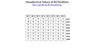
- 5. Hexadecimal Values of Bit Positions Bit 7 Bit 6 Bit 5 Bit 4 Bit 3 Bit 2 Bit 1 Bit 0 0 0 0 0 0 0 0 1 0 0 0 0 0 0 1 0 0 0 0 0 0 1 0 0 0 0 0 0 1 0 0 0 0 0 0 1 0 0 0 0 0 0 1 0 0 0 0 0 0 1 0 0 0 0 0 0 1 0 0 0 0 0 0 0 0x08 0x04 0x02 0x01 0x10 0x20 0x40 0x80 Don’t get Bit by Bit Numbering
- 6. Hexadecimal Values of Bit Positions Examples Bit 7 Bit 6 Bit 5 Bit 4 Bit 3 Bit 2 Bit 1 Bit 0 1 1 0 0 0 0 0 0 0 0 0 0 0 0 1 1 1 1 0 0 0 1 1 1 0 0 0 0 1 1 1 1 1 1 1 1 0 0 0 0 0 0 0 0 0 0 0 0 0 1 0 1 0 1 0 1 1 0 1 0 1 0 1 0 1 1 1 1 1 1 1 1 0x0F 0xC7 0x03 0xC0 0xF0 0x00 0x55 0xAA 0xFF
- 7. Registers • Example of 4-bit binary values converted to a single Hexadecimal character. This 16-bit register value would be shown as: 0x04E0 0000 0100 1110 0000 0x0 0xE 0x4 0x0
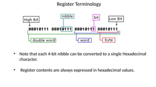
- 8. Register Terminology • Note that each 4-bit nibble can be converted to a single Hexadecimal character. • Register contents are always expressed in hexadecimal values.
- 9. Data Types C Programming Language X X X X X ! ! ! !
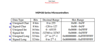
- 10. Data Types Processor Dependent!! MSP430 Series Microcontrollers ! !
- 11. Variable Declaration Modifiers • const – single value at runtime and cannot be altered • volatile – value can be altered anywhere in code (global) • extern – declaration is in another file, but can be used in current file • static – value can be altered only within the current file Examples: volatile unsigned int delay; extern volatile unsigned char i, j, k; static int counter; const int x = 123;
- 12. Constant Declarations There are “constant” variables: const int x = 0x1234; Constant numbers are usually defined with the compiler directive: #define RED 0x11
- 14. C Operations
- 15. C Operations
- 16. C Operations MOST Important Operators in Embedded C Programming ! Used to CLEAR Bits Used to TOGGLE Bits Used to SET Bits Used to INVERT ALL Bits
- 17. HOW TO SET A BIT IN A REGISTER In C programming, the | character is a BITWISE OR NOTE THAT: 0 | 0 = 0 0 | 1 = 1 1 | 0 = 1 1 | 1 = 1 By BITWISE ORing a register with 1s in the bits you want to SET, and 0s in the bits that you want to preserve, YOU ONLY SET THE BITS AT LOCATIONS WHERE THERE ARE A ONES IN THE BYTE USED TO OPERATE ON THE REGISTER
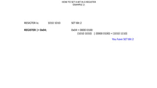
- 18. HOW TO SET A BIT IN A REGISTER EXAMPLE 1: RESIGTER is: 0000 0000 SET Bit 4 REGISTER |= 0x10; 0x10 = 0001 0000 (0000 0000) | (0001 0000) = (0001 0000) You have SET Bit 4
- 19. HOW TO SET A BIT IN A REGISTER EXAMPLE 2: RESIGTER is: 1010 1010 SET Bit 2 REGISTER |= 0x04; 0x04 = 0000 0100 (1010 1010) | (0000 0100) = (1010 1110) You have SET Bit 2
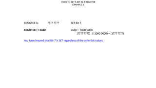
- 20. HOW TO SET A BIT IN A REGISTER EXAMPLE 3: RESIGTER is: ???? ???? SET Bit 7 REGISTER |= 0x80; 0x80 = 1000 0000 (???? ????) | (1000 0000) = (1??? ????) You have insured that Bit 7 is SET regardless of the other bit values.
- 21. HOW TO SET A BIT IN A REGISTER EXAMPLE 4: RESIGTER is: 1111 0000 SET Bits 0 and 1 REGISTER |= 0x03; 0x03 = 0000 0011 (1111 0000) | (0000 0011) = (1111 0011) You have SET bits 0 and 1.
- 22. HOW TO CLEAR A BIT IN A REGISTER In C programming, the & character is a BITWISE AND NOTE THAT: 0 & 1 = 0 1 & 1 = 1 By BITWISE ANDing a register with 1s in the bits you want to preserve, and 0s in the bits that you want to clear, YOU ONLY CLEAR THE BITS AT LOCATIONS WHERE THERE ARE A ZEROS IN THE BYTE USED TO OPERATE ON THE REGISTER
- 23. HOW TO CLEAR A BIT IN A REGISTER EXAMPLE 1: RESIGTER is: 1111 1111 Clear Bit 4 REGISTER &= 0xEF; 0xEF = 1110 1111 SAME AS REGISTER &= ~0x10 (1111 1111) & (1110 1111) = (1110 1111) You have CLEARED Bit 4
- 24. HOW TO CLEAR A BIT IN A REGISTER EXAMPLE 2: RESIGTER is: 1010 1010 Clear Bit 3 REGISTER &= 0xF7; 0xF7 = 1111 0111 SAME AS REGISTER &= ~0x08 (1010 1010) & (1111 0111) = (1010 0010) You have CLEARED Bit 3
- 25. HOW TO CLEAR A BIT IN A REGISTER EXAMPLE 3: RESIGTER is: 0000 0000 Clear Bit 0 REGISTER &= 0xFE; 0xFE = 1111 1110 SAME AS REGISTER &= ~0x01 (0000 0000) & (1111 1110) = (0000 0000) You have insured that Bit 0 is cleared
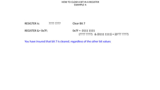
- 26. HOW TO CLEAR A BIT IN A REGISTER EXAMPLE 4: RESIGTER is: ???? ???? Clear Bit 7 REGISTER &= 0x7F; 0x7F = 0111 1111 (???? ????) & (0111 1111) = (0??? ????) You have insured that bit 7 is cleared, regardless of the other bit values
- 27. HOW TO CLEAR A BIT IN A REGISTER EXAMPLE 5: RESIGTER is: 1111 0000 Clear Bits 6 and 5 REGISTER &= 0x9F; 0x9F = 1001 1111 (1111 0000) & (1001 1111) = (1001 0000) You have cleared Bits 6 and 5
- 28. Other Ways to Express the Bit Patterns 0000 1000 = 0x08 = BIT3 1111 0111 = 0xF7 = ~0x08 = ~BIT3 Because a #included header file msp430fr6989.h contains: This is HEX not Binary #define BIT0 (0x0001) #define BIT1 (0x0002) #define BIT2 (0x0004) #define BIT3 (0x0008) #define BIT4 (0x0010) #define BIT5 (0x0020) #define BIT6 (0x0040) #define BIT7 (0x0080) #define BIT8 (0x0100) #define BIT9 (0x0200) #define BITA (0x0400) #define BITB (0x0800) #define BITC (0x1000) #define BITD (0x2000) #define BITE (0x4000) #define BITF (0x8000) NOTE: msp430fr6989.h is #included in driverlib.h
- 29. HOW TO CLEAR A BIT IN A REGISTER EXAMPLE 6: Alternate Notation: RESIGTER is: 1111 0000 Clear Bits 6 and 5 REGISTER &= ~(BIT6 & BIT5); (BIT6 & BIT5) = (0100 0000) & (0010 0000) = 0110 0000 ~(BIT6 and BIT5) = 1001 1111 (1111 0000) & (1001 1111) = (1001 0000) You have cleared bits 6 and 5
- 30. TI Method of Setting BIT Fields of Different Sizes 2*0x1000u DEFINES THE FIRST BIT OF THE FIELD TO BE USED #define BIT0 (0x0001) #define BIT1 (0x0002) #define BIT2 (0x0004) #define BIT3 (0x0008) #define BIT4 (0x0010) #define BIT5 (0x0020) #define BIT6 (0x0040) #define BIT7 (0x0080) #define BIT8 (0x0100) #define BIT9 (0x0200) #define BIT10 (0x0400) #define BIT11 (0x0800) #define BIT12 (0x1000) #define BIT13 (0x2000) #define BIT14 (0x4000) #define BIT15 (0x8000) STEPS: 1. Convert this number to BINARY 2. Place the number in the register with the Least Significant Bit of the field defined by this value (See Table) EXAMPLES: 0010 0000 0000 0000 9*0x0020u: 0000 0001 0010 0000 7*0x2000u: 1110 0000 0000 0000 3*0x0040u: 0000 0000 1100 0000
- 31. 31 Toggling Bits Compliment Bit 0 of register P1OUT P1OUT ^= BIT0; // P1OUT XOR 0x0001 inverts BIT0 only (NOTE: This is the Bitwise Exclusive OR operator: A ZERO retains the bit value of all the positions that are zero. A ONE INVERTS the positions that are 1. Since BIT0 is #defined as 0x0001 it is the only bit complimented. Pretty Cool (not to mention useful). a b XOR 0 0 0 0 1 1 1 0 1 1 1 0
- 32. Programming
- 33. Compiler Directives (from Lecture #1) • #include – append contents of the external file • #define – text substitution for a constant, can assign a numeric value • #pragma – directs compiler to ignore multiple declarations of the same entity • #ifdef – begin conditional compilation, paired with #endif • #ifndef – define only if it hasn’t already been defined • #typedef – defines an alias name or new type
- 34. Function Prototypes void funct1(); void funct1(void); void funct2(unsigned int); unsigned int funct3(void); unsigned int funct4(char); unsigned int funct5(char, unsigned int); NOTE: I put all function prototypes in a separate header file called 3567.h
- 35. Functions Called by Value
- 36. Functions Called by Reference 2
- 37. Local Variables • Declared inside functions • Are not preserved when the execution returns form the function unless returned. void delay_cycles(unsigned int x) { unsigned int a; a = x; while (a >= 0) { a--; } return; }
- 38. Function with Local Variables NOTE: You can return a local variable if the function prototype has a returned parameter
- 39. Loops in Embedded C Use while loops if possible FOR LOOP WHILE LOOP Also a do-while which tests at end. Not used much.
- 40. if-else if or switch ?
- 41. if-else if or switch ? • Use switch statements, for more than 3 conditions AND the values are constants. The cross-compiler will make a jump table (which is way more efficient than multiple tests). • Use if-else if if the cases are Boolean or logical expressions. • In general, most cross-compilers are more efficient with switch. • switch is much more readable (easy to understand), IMHO • For a low number of cases, the difference is negligible.
- 42. How to handle external delays of unknown duration NEVER just wait: (assumes no Watchdog Timer) TAOCTL0 |= CCIE; // Enable process while(CCIF == 0); // CODE HANGS HERE if no event Value = TAOR; // Read Result
- 43. How to handle external delays of unknown duration Method 1: Rely on a Watchdog Timeout TAOCTL0 |= CCIE; // Enable process WDTCTL = WDTPW+WDTCNTCL; //Refresh the Watchdog timer while(CCIF == 0); // Watchdog timer could timeout if enabled Value = TAOR; // Read Result
- 44. How to handle external delays of unknown duration Method 2: Use a down-counter to prevent hanging: timeout = 0x100; while (timeout > 0) { timeout--; if (flag == 1) //external event occurred break; }
- 45. How to handle external delays of unknown duration Method 3a: MEASURE the worst-case latency and add as delay count (slow process) // enable process TAOCTL0 |= CCIE; delay(2000); if (CCIF == 1) // flag checking { Value = TAOR; } Method 3b: MEASURE the worst-case latency and add NOPs (short, fast process) // enable process TAOCTL0 |= CCIE; __no_operation(); // TI NOP macro __no_operation(); // TI NOP macro __no_operation(); // TI NOP macro __no_operation(); // TI NOP macro __no_operation(); // TI NOP macro Value = TAOR;
- 46. Every Cross-Compiler has “Gotchas” Example from Code Composer Studio: void delay(unsigned long delay_count) { while(delay_count > 1) { delay_count--; } return; } Never put a return directly after a loop. The above code is “optimized” out. void delay(unsigned long delay_count) { while(delay_count > 1) { delay_count--; __no_operation(); // TI NOP macro } return; } The NOP fixes the problem
- 47. Registers
- 48. Registers • Control Registers (xxxCTLx)– Module level. Use to configure functions. • Count Registers (xxxR) – Up or down counter • Capture/Compare Registers (xxxCCR) – Work in conjunction with Counters to take action at a certain count. • Capture/Compare Control Registers (xxxCCTLx)– Used to configure what happens when the CCR matches R (counter). • I/O Registers (Ports) – Input/Output ports can have 1 of 4 functions.
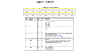
- 49. Control Registers • Every MODULE in a Microcontroller has one or more CONTROL REGISTERS to configure the functions of the module. • Each CONTROL REGISTER is divided into FIELDS • Each FIELD sets one PARAMETER of the MODULE to a specific function • The number of options for the PARAMETER determines the number of BITS in the FIELD • Each BIT has a Power-up DEFAULT value, usually 0.
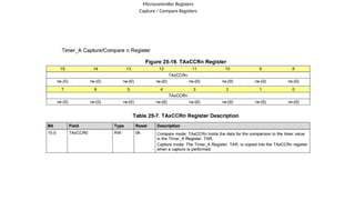
- 52. Microcontroller Registers Capture / Compare Registers
- 53. Capture / Compare Control Registers
- 55. I/O Ports
- 56. Registers Associated with each I/O Port • Input Registers (PxIN) - Read from this one • Output Registers (PxOUT) – Write to this one • Direction Registers (PxDIR) – Control direction of individual bits. • Pullup or Pulldown Resistor Enable Registers (PxREN) – Also bit by bit • Function Select Registers (PxSEL0, PxSEL1) • Interrupt Settings (PxIFG, PxIES, PxIE) NOTE: x – substitute the number of the PORT • 1-10 and J, (8 bit) • A,B,C,D, and E (16 bit)
- 57. I/O Ports - Summary
- 58. I/O Ports
- 59. I/O Ports
- 60. I/O Ports
- 61. I/O Ports
- 62. I/O Ports
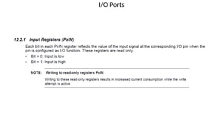
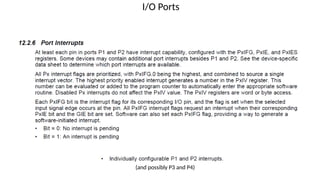
- 63. I/O Ports (and possibly P3 and P4)
- 64. I/O Ports Port Number and Bit Number TI Conventions P3.6 - Bit 6 of Port3 This is the number of the PORT This is the number of the BIT in the PORT
- 65. I/O Ports – Multi-purpose Pins I/O Primary Secondary Tertiary
- 66. I/O Ports – Putting It All Together Bit 7 Bit 6 Bit 5 Bit 4 Bit 3 Bit 2 Bit 1 Bit 0 X X X X X OUT X X X X X X X 1 X X X X X X X 1 X X X X X X X 0 X X X X X X X X X X P2SEL0 P2SEL1 P2DIR P2OUT P2REN Suppose that you wanted to configure BIT 2 of PORT 2 as a Timer B0.4 output for a PWM application
- 67. 67 MSP430FR6989 HARDWARE Quick Start Guide Primary Secondary
- 68. I/O Ports – Putting It All Together Suppose that you wanted to configure BIT 2 of PORT 2 as a Timer B0.4 (Secondary Function) output for a PWM application
- 69. I/O Ports – Putting It All Together Bit 7 Bit 6 Bit 5 Bit 4 Bit 3 Bit 2 Bit 1 Bit 0 X X X X X OUT X X X X X X X 1 X X X X X X X 1 X X X X X X X 0 X X X X X X X X X X P2SEL0 P2SEL1 P2DIR P2OUT P2REN Suppose that you wanted to configure BIT 2 of PORT 2 as a Timer B0.4 (Secondary Function) output for a PWM application P2DIR |= 0x04; P2SEL0 &= ~(BIT2); P2SEL1 |= BIT2;