
![2
level granularity and complex operators and thus try to overcome the disadvantages of FPGAs. As the granularity level increases, routing overhead decreases and this results in increased resource utilization.
In most of the coarse grained reconfigurable architectures, design of an interconnect plays a vital role in determining the performance of the architecture. An interconnect is used to connect the processing elements among themselves and transfers data to/from the processing elements. Network-on-Chip (NoC) is one of the emerging interconnect technologies which can be used as an alternative for the reconfiguration of the entire CGRA. NoC can be implemented using intelligent routers which would control the flow of the reference blocks depending upon the search pattern. Due to this flexibility provided by the NoC using routers, the need to reconfigure the entire architecture to support a different search pattern is eliminated. The implementation of this coarse grained reconfigurable architecture with NoC router [1] is described later in the paper.
The rest of the report is organized as follows: Section II provides the details about the existing work done in the field of CGRAs to implement Motion Estimation. Section III provides the in depth details of the reconfigurable architecture with NoC router [1] that has been implemented. Section IV explains the diamond search and fast search algorithms that are implemented on the architecture. Section V focuses on the enhancement of the architecture [1] that is implemented. Section VI provides the results and analysis of [1] and the enhancement implemented on it, while Section VII concludes the paper.
II. RELATED WORK
Many ASIC based approaches and coarse-grained reconfigurable architectures exist which support Variable Block Size Motion Estimation (VBSME). The ASIC based architectures are classified as partial and parallel sum SAD’s based on the accumulation method of SADs. The reference pixels are broadcasted among all sub- blocks and then the SAD computation is pipelined for each 4x4 sub-block in partial sum SAD architectures. The drawback of this approach is the large number of storage registers (more number of resources) are required to accumulate partial SADs in each processing element. In parallel sum architectures, the SAD computation for a 4x4 sub-block is computed concurrently. ASIC based approaches can also be classified as 1D and 2D systolic arrays based on topology of the architecture. 1D systolic arrays require large number of registers for storing partial SADs and hence incur area overhead and high latency. 2D architectures do not support block sizes smaller than 8x8 and also require more number of storage registers to store reference pixels.
Coarse-grained reconfigurable architectures consist of higher granularity processing elements with flexible and reconfigurable interconnect mechanism. This requires less number of configuration bits than fine-grained reconfigurable architectures like FPGAs. RaPiD [5], MATRIX [3] RAW [2] and ChESS [4], are some of the early designed CGRAs that can be implemented for Motion Estimation.
RaPiD [5] is a coarse-grained field programmable architecture, which is suitable for highly computational intensive Digital Signal Processing applications. It consists of a datapath and a control path which is used to control the datapath. The datapath comprises of a 1D linear array of 16 cells where each cell is made up of a fixed number of ALUs, multipliers, RAM and registers and is called a functional unit. These cells are connected to each other with a reconfigurable interconnect. The interconnect used in RaPiD is a set of ten segmented buses which can be interconnected with each other using bus connectors. The performance provided by this architecture when Motion Estimation is implemented on it, is quite poor. There is a huge underutilization of resources. The parallelism provided by SAD calculation in Motion Estimation has not been exploited completely. In order to compute the SAD of a 16x16 block, the row-wise differences are computed in parallel whereas the column-wise differences are computed in a sequential fashion. As a result of this sequential execution, performance decreases. Moreover the SAD computation operates on 8 bit data but the ALUs and multipliers are of 32 bit, which results in underutilization of resources. Also there are more ALUs present per cell in RaPiD than required as only one ALU will be used to calculate the difference. There is no need for multipliers too. All this again leads to underutilization of resources. Another major disadvantage of this architecture is that it does not supports VBSME.
MATRIX (Multiple ALU architecture with Reconfigurable Interconnect experiment) [3] is one of early coarse- grained reconfigurable architectures. It is composed of a 2D array of basic functional units (BFU), which contains ALU, Multiplier, Instruction and Data memory that supports 256 bytes and a control signal generator](https://image.slidesharecdn.com/ece506projectpaper-141022001602-conversion-gate01/85/Coarse-Grained-Hybrid-Reconfigurable-Architecture-with-NoC-Router-for-Variable-Block-Size-Motion-Estimation-2-320.jpg)
![3
to control ALU, Memory or reduction network. Each BFU can be configured as instruction memory, data memory, ALU or register file. MATRIX architecture supports motion estimation for variable block sizes at the cost of increased complexity of wires.
Reconfigurable arithmetic array for multimedia applications is also called ChESS [4] architecture. The architecture supports strong local connectivity due to its chessboard layout structure. The main components of this architecture are 4-bit ALU and 4-bit bus wiring to provide high computational density; each ALU has a switchbox adjacent to it. The switchbox has dual functionality wherein it can act as a crosspoint with 64 connections and as a RAM when it is not used for routing purpose. This provides the enhanced flexibility. The routing area significantly consumes up to 50% of the total array area which is much less than FPGA. Motion estimation algorithm when mapped on ChESS architecture would require large number of processing elements i.e. the SAD computation for a 16x16 array requires a 512 ALU ChESS array.
III. ARCHITECTURE
Figure 1 shows the implemented hybrid architecture, in which the processing elements are arranged in a 2D fashion. The architecture consists of 16 Configurable Processing Elements (CPE), 4 PE2s, 1 PE3, Memory Interface (MI) and Main Memory. Each CPE consists of a PE1, Network Interface (NI) and a NoC Router. In ME, the current frame and the reference frame are divided into non-overlapping macroblocks of size 16x16. Each macroblock is then divided into 16 4x4 sub-blocks. Each CPE calculates the SAD for a sub- block. Initially all the 16 CPEs will request the current data and reference data via NI from the Main Memory, which is located off chip. When each CPE receives the data through two 32-bit ports, one for current data and the other one for reference data, the SAD for a 4x4 sub-block is calculated by the CPE. Depending upon the block size, the 4x4 result is passed to PE2 and the result of PE2 is passed to PE3. Each CPE interacts with memory through MI, which converts the block id received from NI into actual address and forwards the request to the memory. The memory will send the reference data to the respective CPE. The MI can receive requests from all the CPEs at the same time and the Memory can also serve them in parallel.
Figure 1: Architecture
A. Configurable Processing Element (CPE)
Processing Element (PE1) - As shown in Figure 2, it comprises of five 4 input adders, sixteen 8 bit subtracters, sixteen current pixel registers (CPR) to hold current block data and sixteen reference pixel registers (RPR) to hold reference block data. Among PE1, PE2 and PE3 only PE1 can communicate with the](https://image.slidesharecdn.com/ece506projectpaper-141022001602-conversion-gate01/85/Coarse-Grained-Hybrid-Reconfigurable-Architecture-with-NoC-Router-for-Variable-Block-Size-Motion-Estimation-3-320.jpg)


![12
VII. CONCLUSION
This paper implemented a motion-estimation application-specific coarse-grained and hybrid reconfigurable architecture with a flexible NoC mechanism. Coarse-grained architecture supports higher granularity based computations and hybrid reconfigurable architecture supports Motion-Estimation algorithm for variable block sizes. The architecture by default supports the traditional full search algorithm for motion-estimation. The intelligent NoC mechanism supports VBSME for Diamond Search which is a fast search pattern thereby providing the required flexibility and higher performance. The execution time of Diamond Search decreases by 18.37% when NoC is used as an interconnect. The architecture is further enhanced in which the area overhead is decreased by 4.8% and the router’s power consumption by 42%, thereby forming an area-efficient and power-efficient architecture flexible for supporting full search and diamond search algorithm for VBSME.
REFERENCES
[1] Ruchika Verma, and Ali Akoglu. "A coarse grained and hybrid reconfigurable architecture with flexible NoC router for variable block size motion estimation." In Proceedings of the 22nd IEEE International Parallel and Distributed Processing Symposium (IPDPS), pp. 1-8, 2008.
[2] Waingold, Elliot, Michael Taylor, Devabhaktuni Srikrishna, Vivek Sarkar, Walter Lee, Victor Lee, Jang Kim et al, "Baring it all to software: Raw machines" in IEEE Computer vol. 30, no. 9, pp. 86-93, 1997.
[3] Mirsky, Ethan, and Andre DeHon. "MATRIX: a reconfigurable computing architecture with configurable instruction distribution and deployable resources." In Proceedings of IEEE Symposium on FPGAs for Custom Computing Machines, pp. 157-166, 1996.
[4] Marshall, Alan, Tony Stansfield, Igor Kostarnov, Jean Vuillemin, and Brad Hutchings. "A reconfigurable arithmetic array for multimedia applications." In Proceedings of the 7th ACM/SIGDA International Symposium on Field Programmable Gate Arrays, pp. 135-143, 1999.
[5] Ebeling, Carl, Darren C. Cronquist, Paul Franklin, and Chris Fisher. "RaPiD—a configurable computing architecture for compute-intensive applications,” University of Washington Department of Computer Science & Engineering Tech Report TR-96-11-03, 1996.](https://image.slidesharecdn.com/ece506projectpaper-141022001602-conversion-gate01/85/Coarse-Grained-Hybrid-Reconfigurable-Architecture-with-NoC-Router-for-Variable-Block-Size-Motion-Estimation-12-320.jpg)
Coarse Grained Hybrid Reconfigurable Architecture with NoC Router for Variable Block Size Motion Estimation
- 1. 1 Coarse Grained Hybrid Reconfigurable Architecture with NoC Router for Variable Block Size Motion Estimation Dhiraj Chaudhary, Aditi Sharma, Pruthvi Gowda, Rachana Raj Sunku Department of Electrical and Computer Engineering University of Arizona Tucson, USA Abstract – Coarse-grained reconfigurable architectures are used to provide multi-bit granularity instead of single-bit granularity provided by Field Programmable Gate Arrays (FPGAs). This paper implements an application specific hybrid coarse grained reconfigurable architecture with Network-on-Chip (NoC) which is used to calculate the Sum of Absolute Differences (SAD) for variable block sizes to perform motion estimation used during video compression. The architecture can support full search and diamond search algorithm with minimal resource underutilization. The NoC paradigm is implemented using intelligent routers which can direct data in five directions depending upon the requirement of the algorithm, to reach the destination. This 2D architecture has multiple processing elements which reuse the reference frame blocks among themselves with the help of intelligent NoC routers. The reuse of data reduces the interactions of the architecture with the off chip main memory and hence the execution time of the algorithm decreases. Further, this paper also proposes two enhancements to the implemented architecture wherein the area of the architecture and the power consumption of routers are reduced by 4.8% and 42% respectively. I. INTRODUCTION Advancements in technology have increased the role of digital systems in our day-to-day lives. In this digital world, there is a high demand for faster processing of multimedia applications. This can be achieved using architectures that are flexible and perform computations in a parallel fashion. The architecture has to be adaptive so as to achieve higher performance. H.264 video compression standard plays a vital role in the domain of video compression owing to its high compression efficiency. This can be implemented purely in software or in hardware. In order to transmit the next frame of a video, H.264 calculates the difference of the current frame and the previous frame and transmits this difference instead of transmitting the entire frame. This leads to increased bandwidth usage. Motion Estimation (ME) is one of the most important and computation intensive subroutines of H.264 compression standard. H.264 supports Variable Block Size Motion Estimation (VBSME) as compared to Fixed Block Size Motion Estimation (FBSME). This provides better estimation of small and irregular motion fields and allows better adaptation. In Motion Estimation, a video frame is divided into non-overlapping square blocks which are fixed in number. A square block in the current frame is best matched to a block in the previous frame. For the matching of square blocks, the technique used is Sum of Absolute Differences (SAD). There are seven block sizes that need to be supported by VBSME, which are 16x16, 16x8, 8x16, 8x8, 8x4, 4x8 and 4x4. The adaptability of H.264 compression standard to support VBSME comes at a cost of increased compute intensive subroutines. To implement this feature (VBSME) on hardware, the resource utilization increases drastically. Moreover, the parallelism present in these applications cannot be exploited on general-purpose processors as they are more apt for sequential applications. FPGAs on the other hand can implement these applications (H.264) due to the presence of redundant hardware. The architecture can also be reconfigured on the FPGA depending upon the block size and the block matching algorithms. Highly compute intensive applications, when implemented on FPGA, consumes a lot of time before providing the results due to the bit- level granularity of FPGAs. FPGAs also suffer from routing overhead. Moreover if different search patterns have to be implemented on FPGA during run-time, the hardware has to be divided between those search patterns in order to perform Partial Reconfiguration. This leads to resource underutilization which motivates to switch from FPGAs to Corse Grained Reconfigurable Architectures (CGRAs). CGRAs provide multi-bit
- 2. 2 level granularity and complex operators and thus try to overcome the disadvantages of FPGAs. As the granularity level increases, routing overhead decreases and this results in increased resource utilization. In most of the coarse grained reconfigurable architectures, design of an interconnect plays a vital role in determining the performance of the architecture. An interconnect is used to connect the processing elements among themselves and transfers data to/from the processing elements. Network-on-Chip (NoC) is one of the emerging interconnect technologies which can be used as an alternative for the reconfiguration of the entire CGRA. NoC can be implemented using intelligent routers which would control the flow of the reference blocks depending upon the search pattern. Due to this flexibility provided by the NoC using routers, the need to reconfigure the entire architecture to support a different search pattern is eliminated. The implementation of this coarse grained reconfigurable architecture with NoC router [1] is described later in the paper. The rest of the report is organized as follows: Section II provides the details about the existing work done in the field of CGRAs to implement Motion Estimation. Section III provides the in depth details of the reconfigurable architecture with NoC router [1] that has been implemented. Section IV explains the diamond search and fast search algorithms that are implemented on the architecture. Section V focuses on the enhancement of the architecture [1] that is implemented. Section VI provides the results and analysis of [1] and the enhancement implemented on it, while Section VII concludes the paper. II. RELATED WORK Many ASIC based approaches and coarse-grained reconfigurable architectures exist which support Variable Block Size Motion Estimation (VBSME). The ASIC based architectures are classified as partial and parallel sum SAD’s based on the accumulation method of SADs. The reference pixels are broadcasted among all sub- blocks and then the SAD computation is pipelined for each 4x4 sub-block in partial sum SAD architectures. The drawback of this approach is the large number of storage registers (more number of resources) are required to accumulate partial SADs in each processing element. In parallel sum architectures, the SAD computation for a 4x4 sub-block is computed concurrently. ASIC based approaches can also be classified as 1D and 2D systolic arrays based on topology of the architecture. 1D systolic arrays require large number of registers for storing partial SADs and hence incur area overhead and high latency. 2D architectures do not support block sizes smaller than 8x8 and also require more number of storage registers to store reference pixels. Coarse-grained reconfigurable architectures consist of higher granularity processing elements with flexible and reconfigurable interconnect mechanism. This requires less number of configuration bits than fine-grained reconfigurable architectures like FPGAs. RaPiD [5], MATRIX [3] RAW [2] and ChESS [4], are some of the early designed CGRAs that can be implemented for Motion Estimation. RaPiD [5] is a coarse-grained field programmable architecture, which is suitable for highly computational intensive Digital Signal Processing applications. It consists of a datapath and a control path which is used to control the datapath. The datapath comprises of a 1D linear array of 16 cells where each cell is made up of a fixed number of ALUs, multipliers, RAM and registers and is called a functional unit. These cells are connected to each other with a reconfigurable interconnect. The interconnect used in RaPiD is a set of ten segmented buses which can be interconnected with each other using bus connectors. The performance provided by this architecture when Motion Estimation is implemented on it, is quite poor. There is a huge underutilization of resources. The parallelism provided by SAD calculation in Motion Estimation has not been exploited completely. In order to compute the SAD of a 16x16 block, the row-wise differences are computed in parallel whereas the column-wise differences are computed in a sequential fashion. As a result of this sequential execution, performance decreases. Moreover the SAD computation operates on 8 bit data but the ALUs and multipliers are of 32 bit, which results in underutilization of resources. Also there are more ALUs present per cell in RaPiD than required as only one ALU will be used to calculate the difference. There is no need for multipliers too. All this again leads to underutilization of resources. Another major disadvantage of this architecture is that it does not supports VBSME. MATRIX (Multiple ALU architecture with Reconfigurable Interconnect experiment) [3] is one of early coarse- grained reconfigurable architectures. It is composed of a 2D array of basic functional units (BFU), which contains ALU, Multiplier, Instruction and Data memory that supports 256 bytes and a control signal generator
- 3. 3 to control ALU, Memory or reduction network. Each BFU can be configured as instruction memory, data memory, ALU or register file. MATRIX architecture supports motion estimation for variable block sizes at the cost of increased complexity of wires. Reconfigurable arithmetic array for multimedia applications is also called ChESS [4] architecture. The architecture supports strong local connectivity due to its chessboard layout structure. The main components of this architecture are 4-bit ALU and 4-bit bus wiring to provide high computational density; each ALU has a switchbox adjacent to it. The switchbox has dual functionality wherein it can act as a crosspoint with 64 connections and as a RAM when it is not used for routing purpose. This provides the enhanced flexibility. The routing area significantly consumes up to 50% of the total array area which is much less than FPGA. Motion estimation algorithm when mapped on ChESS architecture would require large number of processing elements i.e. the SAD computation for a 16x16 array requires a 512 ALU ChESS array. III. ARCHITECTURE Figure 1 shows the implemented hybrid architecture, in which the processing elements are arranged in a 2D fashion. The architecture consists of 16 Configurable Processing Elements (CPE), 4 PE2s, 1 PE3, Memory Interface (MI) and Main Memory. Each CPE consists of a PE1, Network Interface (NI) and a NoC Router. In ME, the current frame and the reference frame are divided into non-overlapping macroblocks of size 16x16. Each macroblock is then divided into 16 4x4 sub-blocks. Each CPE calculates the SAD for a sub- block. Initially all the 16 CPEs will request the current data and reference data via NI from the Main Memory, which is located off chip. When each CPE receives the data through two 32-bit ports, one for current data and the other one for reference data, the SAD for a 4x4 sub-block is calculated by the CPE. Depending upon the block size, the 4x4 result is passed to PE2 and the result of PE2 is passed to PE3. Each CPE interacts with memory through MI, which converts the block id received from NI into actual address and forwards the request to the memory. The memory will send the reference data to the respective CPE. The MI can receive requests from all the CPEs at the same time and the Memory can also serve them in parallel. Figure 1: Architecture A. Configurable Processing Element (CPE) Processing Element (PE1) - As shown in Figure 2, it comprises of five 4 input adders, sixteen 8 bit subtracters, sixteen current pixel registers (CPR) to hold current block data and sixteen reference pixel registers (RPR) to hold reference block data. Among PE1, PE2 and PE3 only PE1 can communicate with the
- 4. 4 main memory. PE1 receives the reference data and current data from the main memory and calculates the difference between them using the subtracters. SAD for 4x4 sub-block will be generated using the adders. Comparator will compare the calculated SAD with the previous SAD value and will provide the minimum SAD value out of the two for that particular 4x4 sub-block. Figure 2: PE1 Architecture Network Interface (NI) – NI consists of packetization unit, depacketization unit and control unit, as shown in Figure 3. It is responsible for synchronizing the communication between PE1 and its router and between PE1 and Memory Interface. This synchronization is done using the earlier mentioned three units. If PE1 has completed operating on a reference block, it will send the reference block to its NI. NI will add the header information to it using the packetization unit and will form a complete message of 160 bits (four 32-bit pixel data and one 32 bit header). This information will be sent to the router after receiving an acknowledgement for the request sent by the NI. This router will then send the data to the respective PE1, thus leading to the reuse of the reference block data among the CPEs. If PE1 is the destination node, then it will receive the data through the NI. The NI will extract the reference data using the depacketization unit from the data received through the router. If PE1 needs a reference block that is not present with any other PE1, then it requests that particular reference block by sending the reference_block_id to the NI. NI will send the reference_block_id to the Memory Interface along with the data_load_control signal indicating which CPE needs the data. NoC Router – The router architecture shown in Figure 4 is used to facilitate communication between two PE1s. The router transports the packets from source to destination using XY routing. It comprises of an input controller, 5:1 multiplexer, ring buffer, header decoder, output controller and a 1:5 demultiplexer. The router receives a request from NI and if it is not busy, it will send an acknowledgement to the NI. Then the NI will send the data to the router, which will be received by the 32 bit 5:1 multiplexer and will be stored in the ring buffer. After storing all the packets, the header packet is sent to the header decoder, where the direction of data transfer is extracted. It also updates the header with the remaining number of hops in a particular direction. Depending on the direction of data transfer (North, East, West and South), the data will be sent out of the router to the adjacent router using the 32 bit 1:5 demultiplexer. Before sending the data, the router will
- 5. 5 send a request signal to the corresponding router using the output controller. The input controller of the other router will receive the request and if the router is not busy, will send an acknowledgement back to the sending router. After receiving an acknowledgement, the router will initiate the transfer of data. If the message reaches to the router of the destination node, it will be sent to the NI of the destination node using the PE 1 output of the 1:5 demultiplexer. A router can be involved in only one communication at a point of time. While the router is in the middle of a communication, if its neighboring routers or its own PE attempt to communicate with it, the router denies the new communication. Figure 3: Network Interface (NI) Figure 4: NoC Router PE2 and PE3 – PE2 and PE3, both consist of 3 adders, 2 multiplexers, 2 demultiplexers, 5 comparators and 5 registers as shown in Figure 5. Each PE2 is connected to 4 PE1s and can receive the SAD results from them. Data is forwarded from PE1 to PE2 if SAD needs to be computed on block sizes of 4x8, 8x4 or 8x8 to get the motion vectors. 8x8 SAD is sent to PE3 to get larger block SADs for 8x16, 16x8 or 16x16 block sizes. Communication between PE1 and PE2 does not involve the routers. Routers are only used for communications between PE1s. There are a total of four PE2s and one PE3 in the architecture. All the four PE2s forward their output to the single PE3. Figure 5: Architecture of PE2
- 6. 6 Memory Interface (MI) – It acts as an interface between memory and CPE. CPEs request reference blocks from Main Memory through Memory Interface. Memory Interface after receiving the reference_block_id calculates the memory address of the block requested by the CPE based on the search pattern and sends the address to the memory. Since all the 16 CPEs can request the data at the same time, MI has 16 different ports corresponding to each CPE. IV. FAST SEARCH ALGORITHMS Fast search algorithms, as the name implies, are used to calculate motion estimation faster than regular search patterns, by reducing the number of computations involved. Different kinds of fast search algorithms exist such as diamond search, hexagon search and spiral search. In this paper, we focus on Diamond Search and will compare its performance with the full search algorithm. Diamond Search Diamond Search is a fast search algorithm that reduces the computational intensity by selecting a pattern of 9 reference blocks for each current block in the current frame. The current frame is divided into blocks of size 4x4 and 16 such blocks comprises the macroblock. Each of the 4x4 blocks in a macroblock are loaded into 16 CPEs. Each CPE with a current block computes SAD with 9 reference blocks in the first iteration. Figure 6: Reference Frames for PE1 (1,1) and PE1 (1,3) Each CPE loads the first reference block from memory. However, there exist data dependencies as shown above in the Figure 6. The intersecting search points, which shows the data dependency, are represented by solid squares and solid circles represent other search points. When data dependency is observed, the corresponding reference blocks are loaded from other CPEs, with NI packetizing the reference block data along with the header information and this packet is then forwarded to the corresponding NoC router. The NoC router forwards the packet to the destination node router. The router at the destination node will send the packet to the NI which will depacketize the data to be processed and this reference block data is loaded into the destination CPE followed by the SAD computation. Each CPE accesses a unique reference block and hence eliminates the contention for the same reference block in the same state. Nine SAD’s are computed in each CPE in the first iteration. If the minima is located at the vertex of the diamond, the second search pattern requires SAD to be computed for 5 new reference frames and if the minima is located at the edge of the diamond, then the second search pattern requires SAD to be computed for 3 new reference frames. The search ends when the minima is located at the center of the diamond formed. In that case, a small diamond is formed around the minima. SAD is computed with these 4 reference blocks to find the final minimum SAD.
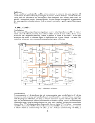
- 7. 7 Full Search This is a traditional search algorithm used for motion estimation. In contrast to fast search algorithm, full search exploits the reference frame by scanning for all reference blocks in the frame. For each block in the current frame, the search for the best matching block spans through the entire reference frame. Hence full search is a computational intensive algorithm. However, the result obtained by this search is accurate than the fast search algorithms where the reference block movement is restricted to a specific region of the reference frame. V. ENHANCEMENT Area Reduction The architecture of the configurable processing element as shown in the Figure 2 consists of five 4 - input, 1- output adders of different granularity. Each of these adders accounts to area overhead. Hence a new architecture for Configurable Processing Element is proposed as shown in the Figure 7. In this CPE architecture, the number of adders are reduced by implementing one 16-input, 1-output 12-bit adder. This results in an architecture, which consumes lesser area than the original architecture. Figure 7: Enhanced PE1 Architecture Power Reduction Power consumption of a device plays a vital role in determining the usage period of a device. If a device consumes too much power and gets heated up faster, it cannot be used for a long time. Various researchers, while designing new architectures, are trying to make the architecture as power efficient as possible. This paper also provides a technique to modify the architecture, as shown in Figure 8, to reduce the router’s power consumption further. In the previous architecture, the router stalls when there is concurrent communication between all the CPE’s. In the diamond search pattern it is observed that the CPE’s of column 1 communicate with CPE’s of column 3 and CPE’s of column 2 communicate with CPE’s of column 4. Consider a scenario in which CPE(1,1) is communicating with CPE(1,3) and CPE(1,2) is communicating with CPE(1,4)
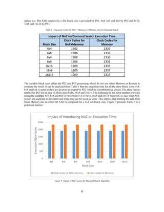
- 8. 8 simultaneously. If CPE(1,1) sends the data to CPE (1,3), it has to send the data through router of CPE(1,2). But if CPE(1,2) sends data to CPE(1,4) simultaneously then the router for CPE(1,1) stalls for few cycles until the data of CPE(1,2) reaches CPE(1,3). Only then, the data of CPE(1,1) will be routed to CPE(1,3) via CPE(1,2)’s router. This increased stall cycles result in an increase in the dynamic power consumption of the router as the stalling router keeps on sending the request to the adjacent router till it receives an acknowledgement from it. We modified the existing symmetric architecture, which eliminates the stall cycles between the CPE’s and thereby reducing the dynamic power consumption of the router. In the modified architecture, the position of the CPE’s of column 2 and Column 3 are swapped to accommodate direct communication. This reduces the router stall cycles, which in turn reduces the dynamic power consumption of the router. The results obtained due to this enhancement are explained in section VI. Figure 8: Enhanced Architecture VI. RESULTS The architecture as mentioned in Section III has been designed using Verilog-HDL description. Table 1 provides the execution times of two iterations of Diamond Search algorithm for seven different block sizes for a frame size of 48x48. These results are obtained for two different scenarios. In one scenario, out of the nine reference blocks in the first iteration, four reference block data are shared between two CPEs using the NoC routers. In the other scenario, there is no reuse of reference data block among the CPEs. All the nine reference block data have been fetched from the Main Memory. During the second iteration, in both the scenarios, all the reference blocks have to be fetched from the Main Memory. As it is well known that retrieving data from Main Memory consumes more time, the execution time for the first scenario in which NoC routers are used, is reduced by 18.37%. Due to reduction in memory interactions, the power consumption of the circuit will
- 9. 9 reduce too. The SAD outputs for a 4x4 block size is provided by PE1, 4x8, 8x4 and 8x8 by PE2 and 8x16, 16x8 and 16x16 by PE3. Table 1 : Execution Cycles for NoC + Memory v/s Memory only for Diamond Search Impact of NoC on Diamond Search Execution Time Block Size Clock Cycles for NoC+Memory Clock Cycles for Memory 4x4 1902 2330 4x8 1908 2336 8x4 1908 2336 8x8 1908 2336 8x16 1909 2337 18x8 1909 2337 16x16 1909 2337 The variable block sizes affect the PE2 and PE3 processing which do not use either Memory or Routers to compute the result. It can be analyzed from Table 1 that the execution time for all the three block sizes, 4x8, 8x4 and 8x8 is same as they are given as an output by PE2 which is a combinatorial circuit. The same reason applies for PE3 too in case of block sizes 8x16, 16x8 and 16x16. The difference in the extra number of cycles needed to compute 4x8, 8x4 and 8x8 or 8x16 from 4x4 or 8x16, 16x8 and 16x16 from 8x8, in case when NoC routers are used and in the other case when they are not used, is same. This implies that fetching the data from Main Memory has an effect till SAD is computed for a 4x4 sub-block only. Figure 9 presents Table 1 in a graphical manner. Figure 9 : Impact of NoC routers for Diamond Search Algorithm 0 500 1000 1500 2000 2500 4x4 4x8 8x4 8x8 8x16 18x8 16x16 Execution Clock Cycles Block Size Impact of Introducing NoC on Execution Time Clock cycles for NOC+Memory Clock cycles for Memory
- 10. 10 Table 2 shows the comparison between the execution time to compute SAD for different block sizes using Full Search and Diamond Search. Full Search, for a particular 4x4 sub-block and a frame size of 48x48, calculates the SAD using 81 reference block data and provides the minimum SAD. Whereas in Diamond Search, minimum SAD using 9 reference blocks for first iteration and 5 reference blocks during next iteration are searched. The computations in Full Search are more as compared to Diamond Search and hence its execution time is very high. It is evident from Table 2, that PE2 and PE3 will have similar effect on the execution time for both Full Search and Diamond Search. The execution time for PE1 to provide the SAD for 4x4 sub-block will differ. Table 2 : Execution Cycles to calculate SAD for Full Search and Diamond Search Comparison of Full Search and Diamond Search Algorithms Block Size Clock Cycles for Diamond Search Clock Cycles for Full Search % Overhead for Full Search 4x4 1902 11911 84.03 4x8 1908 11916 83.99 8x4 1908 11916 83.99 8x8 1908 11916 83.99 8x16 1909 11917 83.98 16x8 1909 11917 83.98 16x16 1909 11917 83.98 As it is evident from Table 2, there is a huge clock cycle overhead when Full Search is used for calculating SAD for a 4x4 sub-block. This implies that we sacrifice the video quality while reconstructing the image using Diamond Search since Diamond Search is not that computation intensive. As the number of computations decreases, resource utilization time decreases and this in turn reduces the power consumption of the architecture. Figure 10 plots the data shown in Table 2. Figure 10 : Comparison of Full Search and Diamond Search Algorithms 0 2000 4000 6000 8000 10000 12000 14000 4x4 4x8 8x4 8x8 8x16 18x8 16x16 Execution Clock Cycles Block Size Comparison of Full Search and Diamond Search Clock cycles for Diamond Search Clock Cycles for Full Search
- 11. 11 Enhanced Architecture – As explained in Section V, this paper implements two enhancement techniques on the implemented architecture mentioned in Section III. Table 3 provides the area consumption of a 10 bit 4 input adder, 12 bit 4 input adder and 12 bit 16 input adder. The Verilog-HDL description for these adders was synthesized for a 45 nm technology using Cadence. Table 3 : Area Utilization of Different Adders Area Utilization 10-bit 4 input adder 12-bit 4 input adder 12-bit 16 input adder 206 μm2 259 μm2 1053 μm2 In the architecture mentioned in Section III, four 10-bit 4 input adders and one 12-bit 4 input adder are used in CPE which results to an area consumption of 1083 μm2 , whereas in the enhanced architecture, a 12- bit 16 input adder uses 1053 μm2. This results in reducing the area of one CPE by 2.77%. There are in total 16 CPEs in the architecture. Each CPEnew is now 0.97*CPEold, hence the area consumed by the enhanced architecture is 4.8 % less than the original architecture. As explained in Section V, the CPE(1,1)’s router stalls during CPE(1,1)’s router to CPE(1,3)’s router communication. In the same manner CPE(1,4)’s router stalls during CPE(1,4)’s router to CPE(1,2)’s router communication. For a sub-block of 4x4, the CPE(1,1), during the first iteration sends the reference block data twice to CPE(1,3). The same applies for CPE(1,4). In the architecture mentioned in Section III, the CPE(1,1)’s router stalls for 19 clock cycles whereas in the enhanced architecture, it stalls for 3 clock cycles (used for sending the request to the adjacent router and receiving the acknowledgement from it). Since CPE(1,1) sends the data twice to CPE(1,3), CPE(1,1)’s router stalls for 38 clock cycles. CPE(1,4)’s router also stalls for 38 clock cycles which results the routers in first row to stall for 76 clock cycles. In the enhanced architecture, the routers stall only for 12 clock cycles. This implies that 64 cycles are being saved by the enhanced architecture. During this period the router only consumes the static power but the dynamic power consumption is zero. The savings in the power consumption are calculated using the formula for dynamic power. The frequency at which the architecture is operating is 25 MHZ. If the enhanced architecture’s router operates at a reduced frequency such that the time consumed by the router while stalling is same in both the architectures, there will be a significant reduction in router’s power as frequency is linearly related to power. If the frequency is 25 MHZ, the time period of the clock cycle is 40 ns. This implies that 76 clock cycles consume 3040 ns whereas 12 cycles consume 480 ns. In order to make 12 cycles consume 3040 ns, the router should operate at a frequency of 4MHZ, hence fnew = 0.16*fold. This implies that frequency decreases by 84 %. Using equation (1), dynamic power for one router is (Pdynamic)new = 0.16 *(Pdynamic)old There are 16 routers in the architecture, which aid communication between the CPEs. As shown in Figure 6, only 8 routers need to operate at the reduced frequency. Hence in Figure 6, if the routers in column 2 and column 3 consume P power, then routers in column 1 and column 4 will consume 0.16*P. So total power consumed by routers in the enhanced architecture is 8*P + (8*0.19)*P = 9.28*P as compared to 16*P. This results in 42% decrease in the total power consumption of the routers in the enhanced architecture. ----(1)
- 12. 12 VII. CONCLUSION This paper implemented a motion-estimation application-specific coarse-grained and hybrid reconfigurable architecture with a flexible NoC mechanism. Coarse-grained architecture supports higher granularity based computations and hybrid reconfigurable architecture supports Motion-Estimation algorithm for variable block sizes. The architecture by default supports the traditional full search algorithm for motion-estimation. The intelligent NoC mechanism supports VBSME for Diamond Search which is a fast search pattern thereby providing the required flexibility and higher performance. The execution time of Diamond Search decreases by 18.37% when NoC is used as an interconnect. The architecture is further enhanced in which the area overhead is decreased by 4.8% and the router’s power consumption by 42%, thereby forming an area-efficient and power-efficient architecture flexible for supporting full search and diamond search algorithm for VBSME. REFERENCES [1] Ruchika Verma, and Ali Akoglu. "A coarse grained and hybrid reconfigurable architecture with flexible NoC router for variable block size motion estimation." In Proceedings of the 22nd IEEE International Parallel and Distributed Processing Symposium (IPDPS), pp. 1-8, 2008. [2] Waingold, Elliot, Michael Taylor, Devabhaktuni Srikrishna, Vivek Sarkar, Walter Lee, Victor Lee, Jang Kim et al, "Baring it all to software: Raw machines" in IEEE Computer vol. 30, no. 9, pp. 86-93, 1997. [3] Mirsky, Ethan, and Andre DeHon. "MATRIX: a reconfigurable computing architecture with configurable instruction distribution and deployable resources." In Proceedings of IEEE Symposium on FPGAs for Custom Computing Machines, pp. 157-166, 1996. [4] Marshall, Alan, Tony Stansfield, Igor Kostarnov, Jean Vuillemin, and Brad Hutchings. "A reconfigurable arithmetic array for multimedia applications." In Proceedings of the 7th ACM/SIGDA International Symposium on Field Programmable Gate Arrays, pp. 135-143, 1999. [5] Ebeling, Carl, Darren C. Cronquist, Paul Franklin, and Chris Fisher. "RaPiD—a configurable computing architecture for compute-intensive applications,” University of Washington Department of Computer Science & Engineering Tech Report TR-96-11-03, 1996.