FYBSC IT Digital Electronics Unit II Chapter I Boolean Algebra and Logic Gates
2 likes961 views

Boolean Algebra and Logic Gates: Introduction, Logic (AND OR NOT), Boolean theorems, Boolean Laws, De Morgan’s Theorem, Perfect Induction, Reduction of Logic expression using Boolean Algebra, Deriving Boolean expression from given circuit, exclusive OR and Exclusive NOR gates, Universal Logic gates, Implementation of other gates using universal gates, Input bubbled logic, Assertion level.


Ad
More Related Content
What's hot (20)
Similar to FYBSC IT Digital Electronics Unit II Chapter I Boolean Algebra and Logic Gates (20)


Ad
More from Arti Parab Academics (20)


Ad
Recently uploaded (20)


FYBSC IT Digital Electronics Unit II Chapter I Boolean Algebra and Logic Gates
- 1. BOOLEAN ALGEBRA AND LOGIC GATES & MINTERM, MAXTERM AND KARNAUGH MAPS UNIT II DIGITAL ELECTRONICS PROF.ARTI GAVAS-PARAB ANNA LEELA COLLEGE OF COMMERCE AND ECONOMICS,SHOBHA JAYARAM SHETTY COLLEGE FOR BMS CHAPTER I
- 2. UNIT II: CONTENTS BooleanAlgebra and Logic Gates: Introduction, Logic (AND OR NOT), Boolean theorems,Boolean Laws, De Morgan’sTheorem, Perfect Induction,Reduction of Logic expression using Boolean Algebra, Deriving Boolean expression from given circuit, exclusive OR and Exclusive NOR gates, Universal Logic gates, Implementation of other gates using universal gates, Input bubbled logic,Assertion level. Minterm, Maxterm and Karnaugh Maps: Introduction, minterms and sum of minterm form, maxterm and Product of maxterm form, Reduction technique using Karnaugh maps – 2/3/4/5/6 variable K-maps,Grouping of variables in K-maps,K-maps for product of sum form, Mminimize Boolean expression using K-map and obtain K-map from Boolean expression, Quine Mc Cluskey Method. C H A P T E R I C H A P T E R II
- 3. BOOLEAN ALGEBRA AND LOGIC GATES Boolean Algebra is the mathematical foundation of digital circuits. Boolean Algebra specifies the relationship between Boolean variables which is used to design combinational logic circuits using Logic Gates. The truth table shows a logic circuit's output response to all of the input combinations. Boolean Algebra A BooleanVariable takes the value of either 0 (False) or 1 (True). Symbols are used to represent Boolean variables e.g.A, B, C,X,Y, Z There are three basic logic operationsAND, OR,NOT The Boolean Operators are • + ‾ A + B means A OR B A • B means A AND B A means NOT A Nodes in a circuit are represented by BooleanVariables The most practical use of Boolean algebra is to simplify Boolean expressions which means less logic gates are used to implement the combinational logic circuit.
- 4. LOGIC GATES Logic gates are electronic circuits that implement the basic functions of Boolean Algebra.There is a symbol for each gate. Logic levels (0 or 1) are represented by means of a voltage level. High voltage (5V,3.3V,2.5V, etc.) is 1 Low voltage (0V) is 0 The table used to represent the boolean expression of a logic gate function is commonly called a TruthTable. A logic gate truth table shows each possible input combination to the gate or circuit with the resultant output depending upon the combination of these input(s). There are “four” possible input combinations or 22 of “OFF” and “ON” for the two inputs. Then the four possible combinations of A and B for a 2-input logic gate is given as: Input Combination 1. – “OFF” – “OFF” or ( 0, 0 ) Input Combination 2. – “OFF” – “ON” or ( 0, 1 ) Input Combination 3. – “ON” – “OFF” or ( 1, 0 ) Input Combination 4. – “ON” – “ON” or ( 1, 1 ) Therefore, a 3-input logic circuit would have 8 possible input combinations or 23 and a 4-input logic circuit would have 16 or 24, and so on as the number of inputs increases.Then a logic circuit with “n” number of inputs would have 2n possible input combinations of both “OFF” and “ON”.
- 5. TYPES OF LOGIC GATES
- 6. 2-INPUT OR (INCLUSIVE OR) GATE For a 2-input OR gate, the output Q is true if EITHER input A “OR” input B is true, giving the Boolean Expression of: ( Q = A or B ). Symbol TruthTable A B Q 0 0 0 0 1 1 1 0 1 1 1 1 Boolean Expression Q = A+B Read as A OR B gives Q
- 7. 2-INPUT AND GATE For a 2-input AND gate, the output Q is true if BOTH input A “AND” input B are both true, giving the Boolean Expression of: ( Q = A and B ). Symbol TruthTable A B Q 0 0 0 0 1 0 1 0 0 1 1 1 Boolean Expression Q = A.B Read as A AND B gives Q
- 8. NOT GATE (INVERTER) For a single input NOT gate, the output Q is ONLY true when the input is “NOT” true, the output is the inverse or complement of the input giving the Boolean Expression of: ( Q = NOT A ). Symbol TruthTable A Q 0 1 1 0 Boolean Expression Q = NOT A or A Read as inversion of A gives Q
- 9. 2-INPUT NAND (NOT AND) GATE For a 2-input NAND gate, the output Q is NOT true if BOTH input A and input B are true, giving the Boolean Expression of: ( Q = not(A AND B) ). Symbol TruthTable A B Q 0 0 1 0 1 1 1 0 1 1 1 0 Boolean Expression Q = A .B Read as A AND B gives NOT-Q
- 10. 2-INPUT NOR (NOT OR) GATE For a 2-input NOR gate, the output Q is true if BOTH input A and input B are NOT true, giving the Boolean Expression of: ( Q = not(A OR B) ). Symbol TruthTable A B Q 0 0 1 0 1 0 1 0 0 1 1 0 Boolean Expression Q = A+B Read as A OR B gives NOT-Q
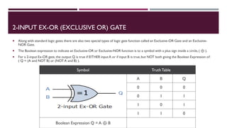
- 11. 2-INPUT EX-OR (EXCLUSIVE OR) GATE Along with standard logic gates there are also two special types of logic gate function called an Exclusive-OR Gate and an Exclusive- NOR Gate. The Boolean expression to indicate an Exclusive-OR or Exclusive-NOR function is to a symbol with a plus sign inside a circle,( ⊕ ). For a 2-input Ex-OR gate, the output Q is true if EITHER inputA or if input B is true,but NOT both giving the Boolean Expression of: ( Q = (A and NOT B) or (NOT A and B) ). Symbol TruthTable A B Q 0 0 0 0 1 1 1 0 1 1 1 0 Boolean Expression Q = A ⊕ B
- 12. 2-INPUT EX-NOR (EXCLUSIVE NOR) GATE For a 2-input Ex-NOR gate, the output Q is true if BOTH input A and input B are the same, either true or false, giving the Boolean Expression of: ( Q = (A and B) or (NOT A and NOT B) ). Symbol TruthTable A B Q 0 0 1 0 1 0 1 0 0 1 1 1 Boolean Expression Q = A ⊕ B
- 13. SUMMARY OF 2-INPUT LOGIC GATES Inputs TruthTable Outputs For Each Gate A B AND NAND OR NOR EX-OR EX-NOR 0 0 0 1 0 1 0 1 0 1 0 1 1 0 1 0 1 0 0 1 1 0 1 0 1 1 1 0 1 0 0 1 Logic Function Boolean Notation AND A.B OR A+B NOT A NAND A .B NOR A+B EX-OR (A.B) + (A.B) or A ⊕ B EX-NOR (A.B) + (A.B) or A ⊕ B The following table gives a list of the common logic functions and their equivalent Boolean notation. The following TruthTable compares the logical functions of the 2- input logic gates discussed. There are many more logic gates with 3, 4 even 8 individual inputs.The multiple input gates are no different to the simple 2-input gates above, So a 4- input AND gate would still require ALL 4-inputs to be present to produce the required output at Q and its larger truth table would reflect that.
- 14. BOOLEANTHEOREMS Boolean theorems and laws are used to simplify the various logical expressions. In a digital designing problem, a unique logical expression is evolved from the truth table. If this logical expression is simplified the designing becomes easier. The Boolean algebra is mainly used in digital electronics, set theory and digital electronics. It is also used in all modern programming languages. There are few basic laws and theorems of Boolean algebra, some of which are familiar to everyone such as Cumulative Law, Associative Law, Distributive law, DeMorgan’sTheorems, Double Inversion law and DualityTheorems.
- 15. BOOLEANTHEOREMS The Cumulative Law The below two equations are based on the fact that the output of an OR or AND gate remains unaffected while the inputs are exchanged themselves. The equation of the cumulative law is given below. The Associative Law The equation is given as These laws illustrate that the order of combining input variables has no effect on the final answer.
- 16. BOOLEANTHEOREMS The Distributive Law The equation is given below. Double Inversion Law The equation is given as The law states that the double complement (complement of the complement) of a variable equals the variable itself.
- 17. BOOLEANTHEOREMS The Identity Law (OR) basic identities of OR operations: The authentication of the above all equations can be checked by substituting the value of A = 0 or A = 1. The Identity Law (AND) basic identities of AND operations: One can check the validity of the above identities by substituting the value of A= 0 or A = 1.
- 18. BOOLEANTHEOREMS The DeMorgan’s theorem The equations are given below. The equation (6) says that a NOR gate is equivalent to a bubbled AND gate, and the equation (7) says that NAND gate is equivalent to a bubbled OR gate. DualityTheorems The new Boolean relation can be derived with the help of Duality theorem.According to this theorem for the given Boolean relation,the new Boolean relation can be derived by the following steps. Changing each OR sign to an AND sign. Changing eachAND sign to an OR sign. Complementing each 0 or 1 appearing in the given Boolean identity. For example: The distributive law states that Now, by using the duality theorem, we can get the new relation by interchanging each OR and AND sign.The equation (8) becomes. The equation (9) is a new Boolean relation. Similarly,for any other Boolean relation,its dual relation can also be derived.
- 19. DEMORGAN’STHEOREM DeMorgan’sTheorem is mainly used to solve the various Boolean algebra expressions. The Demorgan’s theorem defines the uniformity between the gate with same inverted input and output. It is used for implementing the basic gate operation likes NAND gate and NOR gate. The Demorgan’s theorem mostly used in digital programming and for making digital circuit diagrams. There are two DeMorgan’s Theorems. DeMorgan’s FirstTheorem DeMorgan’s SecondTheorem DeMorgan’s first theorem states that two (or more) variables NOR´ed together is the same as the two variables inverted (Complement) and AND´ed, while the second theorem states that two (or more) variables NAND´ed together is the same as the two terms inverted (Complement) and OR´ed. That is replace all the OR operators with AND operators, or all the AND operators with an OR operators.
- 20. DEMORGAN’S FIRSTTHEOREM DeMorgan’s First theorem proves that when two (or more) input variables are AND’ed and negated, they are equivalent to the OR of the complements of the individual variables.Thus the equivalent of the NAND function and is a negative-OR function proving that A.B = A+B and we can show this using the following table. Verifying DeMorgan’s First Theorem usingTruthTable Inputs TruthTable Outputs For EachTerm B A A.B A.B A B A + B 0 0 0 1 1 1 1 0 1 0 1 0 1 1 1 0 0 1 1 0 1 1 1 1 0 0 0 0 DeMorgan’s First Law Implementation using Logic Gates We can also show that A.B = A+B using logic gates as shown.
- 21. DEMORGAN’S SECONDTHEOREM DeMorgan’s Second theorem proves that when two (or more) input variables are OR’ed and negated, they are equivalent to the AND of the complements of the individual variables.Thus the equivalent of the NOR function and is a negative-AND function proving that A+B = A.B and again we can show this using the following truth table. Verifying DeMorgan’s SecondTheorem usingTruth Table DeMorgan’s Second Law Implementation using Logic Gates We can also show that A+B = A.B using logic gates as shown. Inputs TruthTable Outputs For EachTerm B A A+B A+B A B A . B 0 0 0 1 1 1 1 0 1 1 0 0 1 0 1 0 1 0 1 0 0 1 1 1 0 0 0 0
- 22. DEMORGAN’STHEOREM Although we have used DeMorgan’s theorems with only two input variables A and B, they are equally valid for use with three, four or more input variable expressions, for example: For a 3-variable input A.B.C = A+B+C and also A+B+C = A.B.C For a 4-variable input A.B.C.D = A+B+C+D and also A+B+C+D = A.B.C.D And so on.
- 23. PERFECT INDUCTION Perfect induction, Proof by exhaustion, also known as proof by cases, or the brute force method. It is a method of mathematical proof in which the statement to be proved is split into a finite number of cases and each case is checked to see if the proposition in question holds. Perfect induction says that if you check the veracity of a theorem for all possible input combinations, then the theorem is true in its entirety. This is, if it is fulfilled in each case, it is fulfilled in general. This path can be used in Boolean Algebra since the variables have only two possible values: 0 and 1, whilst in our algebra each variable can have infinite values. For example, to demonstrate the distributed property of the sum against the product (which is not fulfilled in common algebra). X+(Y·Z) = (X+Y)·(X+Z) X Y Z X+(Y·Z) (X+Y)·(X+Z) 0 0 0 0 0 0 0 1 0 0 0 1 0 0 0 0 1 1 1 1 1 0 0 1 1 1 0 1 1 1 1 1 0 1 1 1 1 1 1 1 In the table, all possible values for X,Y and Z, the expressions X+(Y·Z) and (X+Y)·(X+Z) are identical, and thus, by perfect induction,both expressions are equivalent.
- 24. TEN BASIC RULES OF BOOLEAN ALGEBRA Sr. No. Rule Equation 1 Anything ANDed with a 0 is equal to 0. A * 0 = 0 2 Anything ANDed with a 1 is equal to itself. A * 1 = A 3 Anything ORed with a 0 is equal to itself. A + 0 = A 4 Anything ORed with a 1 is equal to 1. A + 1 = 1 5 Anything ANDed with itself is equal to itself. A * A = A 6 Anything ORed with itself is equal to itself. A + A = A 7 Anything ANDed with its own complement equals 0. 8 Anything ORed with its own complement equals 1. 9 Anything complemented twice is equal to the original. 10 The two variable rule.
- 25. TEN BASIC RULES OF BOOLEAN ALGEBRA Boolean Expression Boolean Algebra Law or Rule A + 1 = 1 Annulment A + 0 = A Identity A . 1 = A Identity A . 0 = 0 Annulment A + A = A Idempotent A .A = A Idempotent NOT A’ = A Double Negation Boolean Expression Boolean Algebra Law or Rule A + A’ = 1 Complement A .A’ = 0 Complement A+B = B+A Commutative A.B = B.A Commutative (A+B)’ = A’.B’ de Morgan’sTheorem (A.B)’ = A’+B’ de Morgan’sTheorem
- 26. REDUCTION OF LOGIC EXPRESSION USING BOOLEAN ALGEBRA Complex combinational logic circuits must be reduced without changing the function of the circuit. Reduction of a logic circuit means the same logic function with fewer gates and/or inputs. The first step to reducing a logic circuit is to write the Boolean Equation for the logic function. The next step is to apply as many rules and laws as possible in order to decrease the number of terms and variables in the expression. To apply the rules of Boolean Algebra it is often helpful to first remove any parentheses or brackets. After removal of the parentheses,common terms or factors may be removed leaving terms that can be reduced by the rules of Boolean Algebra. The final step is to draw the logic diagram for the reduced Boolean Expression.
- 27. SIMPLIFICATION: EXAMPLE 1 Using the above laws, simplify the following expression: (A + B)(A + C) Q = (A + B).(A + C) A.A + A.C + A.B + B.C – Distributive law A + A.C + A.B + B.C – IdempotentAND law (A.A = A) A(1 + C) + A.B + B.C – Distributive law A.1 + A.B + B.C – Identity OR law (1 + C = 1) A(1 + B) + B.C – Distributive law A.1 + B.C – Identity OR law (1 + B = 1) Q = A + (B.C) – IdentityAND law (A.1 = A) Then the expression: (A + B)(A + C) can be simplified to A + (B.C) as in the Distributive law. Draw Logic Diagram for previous expression and simplified expression.
- 28. SIMPLIFICATION: EXAMPLE 2 Previous Example can also be solved in following manner:
- 29. SOME EXAMPLES OF SIMPLIFICATION
- 30. DERIVING BOOLEAN EXPRESSION FROM GIVEN CIRCUIT Sometimes,we need to be able to derive the Boolean expression of a logic gate diagram.We might want to do this, for example, so that we can investigate simplifying the design.We will look at some examples of this now. Example 1 Consider the following circuit gate diagram: Next, you need to start on the left and work your way through each part, working out what the output is after each gate. After part 1, we haveA.B and A + B After part 2, we have invertedA.B so we now haveA.B After part 3, we have put the parts together in an AND gate from part 2 and have (A.B)(A + B) Let's draw out the truth table for this diagram:
- 31. DERIVING BOOLEAN EXPRESSION FROM GIVEN CIRCUIT: EXAMPLE Example 2 Consider the following logic gate diagram. Example 3 It doesn't matter how many inputs you have,or even if your circuit diagram includes NAND or NOR gates. Consider the following logic gate diagram.
- 32. GENERATING SCHEMATIC DIAGRAMS FROM BOOLEAN EXPRESSIONS Example: B(A + C) To do this, evaluate the expression, following proper mathematical order of operations (multiplication before addition, operations inside parentheses before anything else), and draw gates for each step. Remember again that OR gates are equivalent to Boolean addition, while AND gates are equivalent to Boolean multiplication. In this case, we would begin with the sub-expression “A + C”, which is an OR gate. The next step in evaluating the expression “B(A + C)” is to multiply (AND gate) the signal B by the output of the previous gate (A + C). Step 1: Step 2:
- 33. GENERATING SCHEMATIC DIAGRAMS FROM BOOLEAN EXPRESSIONS: EXAMPLES Consider the Boolean expression AB+CD. The corresponding digital logic circuit is: Other examples:
- 34. GENERATING SCHEMATIC DIAGRAMS FROM BOOLEAN EXPRESSIONS: HOMEWORK 1. Draw digital logic circuits for these Boolean expressions: 1. Give the equivalent Boolean expressions for these digital logic circuits
- 35. UNIVERSAL LOGIC GATES & IMPLEMENTATION OF OTHER GATES USING UNIVERSAL GATES They are called as “Universal Gates” because- They can realize all the binary operations. All the basic logic gates can be derived from them. They have the following properties- Universal gates are not associative in nature. Universal gates are commutative in nature. There are following two universal logic gates- NAND Gate NOR Gate 1. NAND Gate- A NAND Gate is constructed by connecting a NOT Gate at the output terminal of the AND Gate. The output of NAND gate is high (‘1’) if at least one of its inputs is low (‘0’). The output of NAND gate is low (‘0’) if all of its inputs are high (‘1’). 2. NOR Gate- A NOR Gate is constructed by connecting a NOT Gate at the output terminal of the OR Gate. The output of OR gate is high (‘1’) if all of its inputs are low (‘0’). The output of OR gate is low (‘0’) if any of its inputs is high (‘1’).
- 36. NAND GATE IS A UNIVERSAL GATE NAND gates can be connected to form any other logic gates. Figures 1,2,3 show how NAND gates can be connected to form INVERTER,AND, and OR gates. These gates can be combined to form the other logic gates according to the symbolic logic definitions.
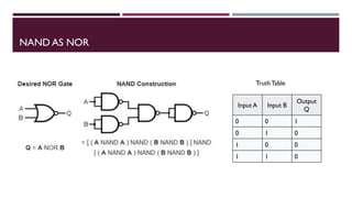
- 37. NAND AS NOR Input A Input B Output Q 0 0 1 0 1 0 1 0 0 1 1 0 TruthTable
- 38. NAND AS XOR Input A Input B Output Q 0 0 0 0 1 1 1 0 1 1 1 0 TruthTable
- 39. NAND AS XNOR Input A Input B Output Q 0 0 1 0 1 0 1 0 0 1 1 1 TruthTable
- 40. NOR GATE IS A UNIVERSAL GATE NOT gate is made by joining the inputs of a NOR gate.As a NOR gate is equivalent to an OR gate leading to NOT gate, this automatically sees to the "OR" part of the NOR gate, eliminating it from consideration and leaving only the NOT part. An OR gate is made by inverting the output of a NOR gate. Note that we already know that a NOT gate is equivalent to a NOR gate with its inputs joined. An AND gate gives a 1 output when both inputs are 1. Therefore, an AND gate is made by inverting the inputs of a NOR gate.Again, note that a NOT gate is equivalent to a NOR with its inputs joined.
- 41. NOR AS NAND Input A Input B Output Q 0 0 1 0 1 1 1 0 1 1 1 0 TruthTable
- 42. NOR AS XNOR Input A Input B Output Q 0 0 1 0 1 0 1 0 0 1 1 1 TruthTable
- 43. NOR AS XOR Input A Input B Output Q 0 0 0 0 1 1 1 0 1 1 1 0 TruthTable
- 44. INPUT BUBBLED LOGIC:ALTERNATIVE LOGIC GATES Alternative logic gate is an alternate logic gate that produces the same output as the original logic gate. and can be used during the unavailability of the original logic gate to serve the same purpose. Alternative logic gates are also called as Alternate Gates. Alternative logic gates are also called as Bubbled Gates since they contain bubbles in them. The following table shows the original logic gate and its corresponding alternate gate Bubble pushing is a technique to apply De Morgan's theorem directly to the logic diagram. 1. Change the logic gate (AND to OR and OR to AND). 2. Add bubbles to the inputs and outputs where there were none, and remove the original bubbles.
- 45. ASSERTION LEVEL Assertion level is the voltage level in a logic circuit that represents a logical "1". Common level for high = +5v and low = 0v. A logical AND circuit that operates with assertion high (also called positiveAND) requires high level on all inputs to yield a high output. If you change your terms of reference to assertion low, then the exact same circuit becomes an OR - any low input yields a low output (also called negative OR). PositiveAND == Negative OR Assertion in this case simply means in which value is the pin active. Digital Circuits have 1st High Assertion Logic Level From theView Point of Gates (Circuit) the Digital Signal PulseTrain has a ZERO (0-0.8V) logic level as a LOW and ONE (approx 2- 5V) Logic level as HIGH 2nd Low Assertion Logic Level From theView Point of Gates (Circuit) the Digital Signal PulseTrain has a ZERO (0-0.8V) logic level as a HIGH and ONE (approx 2- 5V) Logic level as LOW Low Assertion Logic level is indicated by a bubble at either input and/or output of a gate.
- 46. THANKYOU!