SlideShare a Scribd company logo
GSM Architecture
1
GSM SubSystems
GSM architecture is mainly divided into three
Subsystems
1. Base Station Subsystem (BSS)
2. Network & Switching Subsystem (NSS)
3. Operations & Support Subsystem (OSS)
Mobile Station sometimes included in BSS
2
GSM Network Architecture
4
Um I/ F
MS
BTS
B
S
C
T C MSC PSTN
VLR
HLR AUC
EIR
A-bis
I/F
A-ter
I/F
A
I / F
Simplified GSM Architecture
5
6
7
Mobile Station (MS)
The MS consists of two parts
1. Mobile Equipment (ME)
2. Subscriber Identity module (SIM)
8
+
G S M
Global GSM Mobility
Card
The Smart Card to use
SIM Card
+
Battery
Handset
battery
2W
jmhfod
kgdjipj
f153454
Mobile Station
=
Mobile Station
G S M
Global GSM Mobility
Card
The Smart Card to use
+
SIM-Card
Handset
Subscriber knows
- Called party number = MS-ISDN
- PIN
Contains:
- IMSI
=
Calling line
0609225831
SIM-Card and GSM Mobile
Equipment
25 mm
15 mm
Microchip with stored
user information
Credit Card Size
Permanent data:
- Unique mobile subscriber identity
through IMSI number,
- Authentication parameter Ki,
- Authentication algorithm A3,
- Generating encryption key Kc
algorithm A8.
Removable data:
- Temporary Mobile Subscriber Number,
- Location Area Identification.
µ SIM-Card
G S M
Global GSM Mobility
Card
The Smart Card to use
The SIM-Card Functions
Nature
International Mobile Subscriber Identity
Conformity with E212
Mobile Station -
Integrated Services Digital Network Nb
Similar to ISDN,
Conformity with E164/E213
Nb. digits 3 2 max 10 1 to 3 2 to 4 total max 15
*
This code does not identify a geographical area
but an operator
MS - ISDN
Format MCC MNC MSIN
H1 H2 x x x ......... x x x
CC NDC SN
M1 M2 x x x x x x x x
Meaning
Mobile
Country
Code
Mobile
Network
Code
Mobile Subscriber
Ident. Nb
H1 H2 = Identity of HLR
within the home PLMN
Country
Code
(where
subscription
has been made)
National
Destination
Code *
Mobile Subscriber
(national definition)
M1 M2 = nbr of logical HLR
IMSI
National Significant Mobile Number
Identify a PLMN
worldwide
Identify the subscriber
of a PLMN
Subscriber Identification
Type Approval
Code
TAC FAC SNR SP
Final Assembly
Code
Serial number (SPare)
Mobile Identification
Pocket
Hands-free Data
Booster
2 W 5 W
2 W 8 W
Fax Organizer
PC
Dual-band
900-1800
900-1900
Java
Trends in Mobile Station
Mobile Equipment (ME)
• The ME is the only part of the GSM network
which the subscriber will really see.
• There are three main types of ME, these are
listed below:
1. Vehicle Mounted
2. Portable Mobile Unit
3. Hand portable Unit
15
 The SIM is a card which plugs into the ME.
 This card identifies the MS subscriber and also provides
other information regarding the services that subscriber
should receive.
 The SIM card, and the high degree of inbuilt system security,
provides protection of the subscriber’s information and
protection of networks against fraudulent access.
 The SIM can be protected by use of Personal Identity
Number (PIN) password, similar to bank/credit charge cards,
to prevent unauthorized use of the card.
 SIM cards are designed to be difficult to duplicate.
 By making a distinction between the subscriber identity and
the ME identity, GSM can route calls and perform billing
based on the identity of the ‘subscriber’ rather than the
equipment or its location.
Subscriber Identity module (SIM)
16
The SIM contains several pieces of information:
1. International Mobile Subscriber Identity (IMSI)
2. Temporary Mobile Subscriber Identity (TMSI)
3. Location Area Identity (LAI)
4. Subscriber Authentication Key (Ki)
5. Mobile Station Integrated Services Digital
Network (MSISDN)
The SIM is capable of storing additional information
such as accumulated call charges.
The SIM also executes the Authentication Algorithm.
Subscriber Identity module Cntd….
17
Subscriber Identity module Cntd….
18
Base Station Subsystem (BSS)
19
TCU
BSC
OMC-R
MSC
Radio
Interface
A Interface
Ater Interface
Abis Interface
NSS
BSS
OMN Interface
Public Telephone Network
MS
MS
S2000H&L
BTS
S8000
Indoor
BTS
S8000
Outdoor
BTS
Sun
StorEdge A5000
Radio
Interface
BSS Architecture
Base Station Controller (BSC)
the BSC provides the control for the BSS.
Any operational information required by the BTS will
be received via the BSC.
Likewise any information required about the BTS (by
the OMC for example) will be obtained by the BSC.
The BSC incorporates a digital switching matrix, which
it uses to connect the radio channels on the air interface
with the terrestrial circuits from the MSC.
The BSC switching matrix also allows the BSC to
perform “handovers” between radio channels on BTSs,
under its control, without involving the MSC.
21
22
BTS Abis interface A interface
- Radio Resource
management for its BTSs
- Intercell hand-over
- Allocation of channels for
communication
- Reallocation of frequencies
among BTSs
- Time and frequency
synchronization to BTSs
- Controls frequency
hopping
O&M
To Network
SubSystem
PCM
controller
PCM
controller
Processing
Unit
Switching
matrix
BSC
X.25
controller
BSC General Architecture and Functions
Base Transceiver Station – BTS
• The BTS provides the air interface connection
with the MS.
• It also has a limited amount of Control
functionality which reduces the amount of
traffic passing between the BTS and BSC.
• Where the BSC and BTS are both shown to
control a function, the control is divided
between the two, or may be located wholly at
one.
24
25
Transmission coupler
Reception coupler
Antenna
COUPLING SYSTEM
BCF
(Base Common Functions)
BSC
TRX
(Transceiver-Receiver)
Abis
interface
- Encodes, encrypts, modulates,
feeds the RF signal to the
antenna
- Decrypts and equalizes the
signal then demodulates
- Mobile call detection
- Uplink channel measurements
- Timing advance
- Frequency hopping
- Multiplexes speech and user's data channels to BSC.
- Multiplexes signaling channels to BSC.
Duplexer
- Interface between Antennas
and TRXs of each cell
BTS
BTS General Architecture and Functions
27
BSS Configurations
• The maximum number
of BTSs which may be
controlled by one BSC is
not specified by GSM.
•The BTSs and BSC may
either be located at the
same cell site “co-
located”, or located at
different sites “Remote”.
•Another BSS
configuration is the daisy
chain.
•Problem- transmission
delay through the chain.
28
External PCM
Interface
BSC MSC
Transcoder
Transcoder
Controller
Ater
interface
A
interface
E1 trunk
up to 120 user's
channels
T1 trunk
up to 92 user's
and
control channels
Converts the 13 kbps GSM speech frame either
into a 64 kbps T1 PCM µ-law or into an E1 PCM A-law
E1 trunk = up to
31 user's channels
T1 trunk = up to
24 user's channels
Routes the users' data stream
to suitable Inter-working function
TRAU
TRAU Architecture and Functions
Transcoder (XCDR)
• The 64 kbit/s PCM circuits from the MSC, if
transmitted on the air interface without
modification, would occupy an excessive
amount of radio bandwidth.
• The Transcoder is to convert the speech or data
output from the MSC into the form suitable for
transmission over the air interface.
• The required bandwidth is therefore reduced by
processing the 64 kbit/s circuits so that the
amount of information required to transmit
digitized voice falls to a gross rate of 16 kbit/s.
30
• The transcoding function may be located at the MSC,
BSC, or BTS.
• The content of the 16 kbit/s data depends on the coding
algorithm used.
• There are two speech coding algorithms available.
• The Full Rate speech algorithm is supported by all
mobiles and networks.
• It produces 13 kbit/s of coded speech data plus 3 kbit/s
of control data known as TRAU data (Transcoder Rate
Adaptation Unit).
• TRAU only used by BTS and discarded (not
transmitted on air interface)
Transcoder (XCDR) Cntd….
31
• the 13 kbit/s of speech data is processed at the
BTS to form a gross rate of 22.8 kbit/s on the air
interface which includes forward error correction.
• In the uplink direction the BTS adds in TRAU
data which will be used by the transcoder.
• Enhanced Full Rate is an improved speech coding
algorithm and is only supported by Phase 2+
mobiles.
• It produces 12.2 kbit/s from each 64 kbit/s PCM
channel and TRAU data of 3.8 kbits/s
Transcoder (XCDR) Cntd….
32
33
Network Switching System (NSS)
34
MSC
AUC
GMSC
BSS
Other GSM,
PSTN, ISDN
G-interface
IWF IWF
Site 2
C-interface
A-interface A-interface
B-interface B-interface
E
F
E
F
H
D
D
BSS
Other GSM,
PSTN, ISDN E-interface
Site 1
NSS Architecture
VLR
HLR
VLR
EIR
SMS-SC Billing
Server
Billing
Server
Network Switching System (NSS)
• The Network Switching System includes the main
switching functions of the GSM network.
• It also contains the databases required for subscriber
data and mobility management.
• The components of the Network Switching System are
listed below:
1. Mobile Services Switching Centre – MSC
2. Home Location Register – HLR
3. Visitor Location Register – VLR
4. Equipment Identity Register – EIR
5. Authentication Centre – AUC
6. Interworking Function – IWF
7. Echo Canceller – EC
36
37
Mobile Switching Centre (MSC)
 MSC is the heart of the system, controlling the
Switching & Billing.
 The MSC can carry out different functions depending
upon its position in the network.
 When provides interface between PSTN & BSS in GSM
network then known as a Gateway MSC
 provides service to MSs located within a defined
geographic coverage area.
 The network typically contains more than one MSC.
 One MSC is capable of supporting a regional capital
with approximately one million inhabitants.
38
• Call Processing
1. control of data/voice call setup
2. inter-BSS and inter-MSC handovers
3. control of mobility management (subscriber validation
and location).
• Operations and Maintenance Support
1. database management
2. traffic metering and measurement
3. A Man–machine interface.
• Internetwork Interworking
1. Interface between the GSM network and the PSTN.
• Billing
1. Collects call billing data.
MSC’s Functionalities
39
Subscriber
Management
Center
HLR
Permanent records
- MSISDN
- IMSI
- Subscriber's service provision
Temporary records
- VLR address
- Ciphering items
(Kc, Sres, Rand)
Home Location Register
Home Location Register (HLR)
 The HLR is the master database which contains
each user’s service profile.
 Various identification numbers and addresses are
stored, as well as authentication parameters.
 The data it contains is remotely accessed by all the
MSCs and the VLRs in the network.
 Although the network may contain more than one
HLR, there is only one database record per
subscriber .
 The subscriber data may be accessed by either the
IMSI or the MSISDN number.
41
VLR
Permanent records
- IMSI
- Subscriber’s service provision
Temporary records
- Ciphering items
(Kc, Sres, Rand)
- LAI - TMSI
LA1
LA4
LA2
LA3
Visitor Location Register
 VLR is a temporary database for all user
currently located in the system including roamers
& non-roamers.
 The data exists for only as long as the subscriber is
“active” in the particular area covered by the
VLR.
 The VLR database will therefore contain some
duplicate data as well as more precise data
relevant to the subscriber.
 This function eliminates the need for excessive
and time-consuming references to the “home”
HLR database.
Visitor Location Register (VLR)
43
The additional data stored in the VLR is listed
below:
1. Mobile status (busy/free/no answer etc.).
2. Location Area Identity (LAI).
3. Temporary Mobile Subscriber Identity (TMSI).
4. Mobile Station Roaming Number (MSRN).
• MSC updates VLR with HLR information.
• Each MSC has VLR which resides with the MSC
& each G-MSC has a HLR which usually resides
with the G-MSC
Visitor Location Register Cntd….
44
EIR
Black list
(barred ME)
Gray list
(faulty ME)
White list
(valid ME)
Mobile
Equipment
IMEI
Equipment Identity Register
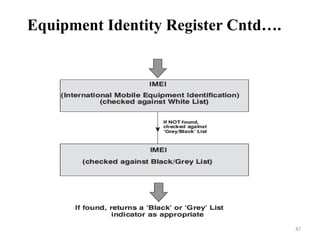
• The EIR contains a centralized database for
validating the IMEI.
• This database is concerned solely with MS
equipment and not with the subscriber who is
using it to make or receive a call.
• The EIR database consists of lists of IMEIs (or
ranges of IMEIs) organized as follows:
1. White List
2. Black List
3. Grey List
Equipment Identity Register (EIR)
46
Equipment Identity Register Cntd….
47
AUC
Security
A3, A8 algorithms
Ki
5
SRES, Kc, RAND
RAND
AUC provides
Ciphering Triplets
IMSI
HLR Request
Authentication Center
Authentication Centre (AuC)
• The AuC is a processor system that performs
the “authentication” function.
• It is normally co-located with the HLR as it
will be required to continuously access and
update, as necessary, the system subscriber
records.
• The authentication process will usually take
place each time the subscriber “initializes” on.
49
Mobile
Switching
Center
IWF
MS
BSS PSTN
DTE
Land-DTE
Rate
adaptation
DTE
signaling
Modem
Modem
Data +
DTE signals
InterWorking Function
Interworking Function (IWF)
• IWF provides the function to enable the GSM
system to interface with the various forms of
public and private data networks.
• The basic features of the IWF are
1. Data rate adaptation.
2. Protocol conversion.
• Some systems require more IWF capability
than others, this depends upon the network to
which it is being connected.
51
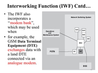
Interworking Function (IWF) Cntd…
• The IWF also
incorporates a
‘‘modem bank”,
which may be used
when
• for example, the
GSM Data Terminal
Equipment (DTE)
exchanges data with
a land DTE
connected via an
analogue modem.
52
Echo Canceler
Mobile
Switching
Center
Base
Station
SubSystem
Echo
Canceler
Switch
Land telephone
4w to 2w
transformer
GSM network
4 wire circuit PSTN
Local
loop
Talker Echo
Two wire circuit
4 wire
circuit
Talker
Echo
4 wire
circuit
(PCM)
Echo Canceller (EC)
• An EC is used on the PSTN side of the MSC for
all voice circuits.
• Echo control is required at the switch because
the inherent GSM system delay(180 ms approx)
can cause an unacceptable echo condition.
• This would not be apparent to the MS
subscriber, but for the inclusion of a 2-wire to
4-wire hybrid transformer in the circuit.
• The transformer causes the echo. This does not
affect the land subscriber.
54
Echo Canceller (EC) cntd….
55
• During a normal PSTN land to land call, no
echo is apparent because the delay is too short.
• without the EC, the effect would be very
irritating to the MS subscriber.
• disrupting speech and concentration.
• EC provides cancellation of up to 68 ms on the
“tail circuit”.
• the tail circuit is the connection between the
output of the EC and the land telephone.
Echo Canceller (EC) cntd….
56
57
Operations & Support System (OSS)
58
Operations & Support System (OSS)
• The OSS provides the capability to manage
the GSM network remotely.
• This area of the GSM network is not currently
tightly specified by the GSM specifications.
• It is left to the network provider to decide what
capabilities they wish it to have.
• The Operations and Maintenance System
comprises of two parts:
1. Network Management Centre (NMC)
2. Operations and Maintenance Centre (OMC)
59
Operations & Support System Cntd....
60
Operations & Support System Cntd....
61
Network Management Centre (NMC)
62
Operations and Maintenance Centre
(OMC)
 The OMC provides a central point from which to
control and monitor the other network entities (i.e. base
stations, switches, database, etc).
 It also monitors the quality of service being provided
by the network.
 There are two types of OMC these are:
1. OMC-R
OMC controls specifically the Base Station System.
2. OMC-S
OMC controls specifically the Network Switching
System.
63
The OMC should support the following
functions as per ITS–TS recommendations:
1. Event/Alarm Management.
2. Fault Management.
3. Performance Management.
4. Configuration Management.
5. Security Management.
Operations and Maintenance Centre Cntd….
64
Operations and Maintenance Centre Cntd….
65
66
Network in Reality
• In reality a GSM network is much more
complicated than we have seen.
• The diagram in the next slide illustrates how
multiple BSS and Network Switching System
components will be connected within a
network
67
68
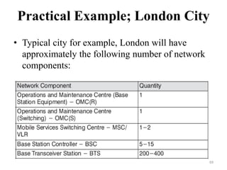
Practical Example; London City
• Typical city for example, London will have
approximately the following number of network
components:
69
• A typical network (for example, UK) will have
approximately the following number of network
components.
Mobile Network in U.K
70
Ad

Recommended

PDF
IIJmio meeting 31 MVNOの音声通話を巡る最新状況
techlog (Internet Initiative Japan Inc.)
 
PPTX
Home enodeb with tr069
Sasi Reddy
 
PPT
Lte most used command rev1
Christofer Dinamiko
 
PPTX
インターネッツの繋がるしくみ(TCP/IP編) #sa_study
Shinichiro Yoshida
 
PDF
abc031
AtCoder Inc.
 
PDF
Advantages & disadvantages of 3g network
Muhib Zaman
 
PPTX
Rf planning doc
Bhumika Katyal
 
KEY
OpenvswitchでVPS
Daisuke Nakajima
 
PDF
config_mini link
Amir Moradi
 
PDF
Hsdpa principles
Abdulqader Al-kaboudei
 
PDF
Indeedなう B日程 解説
AtCoder Inc.
 
PPTX
NSN NOKIA 3G KPI for Network planning and optimization
Yogender Singh Rana
 
PPTX
ZDD基礎
reew2n
 
PPTX
LTE DownLink Frame Structure - Copy.pptx
mani723
 
PPT
370410176 moshell-commands
nanker phelge
 
PDF
AtCoder Beginner Contest 019 解説
AtCoder Inc.
 
PDF
Openstack kolla 20171025 josug v3
Takehiro Kudou
 
PDF
Ericsson LTE Commands.pdf
MbBot
 
PPSX
146661638 configuring-rbs-6201-gsm-with-rus
Syed Ahmad
 
PPTX
The five stages of grief
SD Shyu
 
PDF
Minilink TN Ethernet Config.pdf
FahruddinThaha
 
DOCX
Tele Communications - IEEE 802.11
Shefa Idrees
 
PDF
Chap 2 - Etudiant.pdf
kohay75604
 
PPTX
Sdcch drop rate
Terra Sacrifice
 
PDF
coverage_enhancement
mohammad ali amini
 
PDF
平行運算介紹
Affiliate marketing
 
PPTX
Nmap 9つの真実
abend_cve_9999_0001
 
PDF
Wireless module 2 notes vtu 18ec81 GSM Module
Chetan Naik
 
PPTX
GSM.pptx full gsm solution of final exam
PranitVichare2
 

More Related Content

What's hot (20)

PDF
config_mini link
Amir Moradi
 
PDF
Hsdpa principles
Abdulqader Al-kaboudei
 
PDF
Indeedなう B日程 解説
AtCoder Inc.
 
PPTX
NSN NOKIA 3G KPI for Network planning and optimization
Yogender Singh Rana
 
PPTX
ZDD基礎
reew2n
 
PPTX
LTE DownLink Frame Structure - Copy.pptx
mani723
 
PPT
370410176 moshell-commands
nanker phelge
 
PDF
AtCoder Beginner Contest 019 解説
AtCoder Inc.
 
PDF
Openstack kolla 20171025 josug v3
Takehiro Kudou
 
PDF
Ericsson LTE Commands.pdf
MbBot
 
PPSX
146661638 configuring-rbs-6201-gsm-with-rus
Syed Ahmad
 
PPTX
The five stages of grief
SD Shyu
 
PDF
Minilink TN Ethernet Config.pdf
FahruddinThaha
 
DOCX
Tele Communications - IEEE 802.11
Shefa Idrees
 
PDF
Chap 2 - Etudiant.pdf
kohay75604
 
PPTX
Sdcch drop rate
Terra Sacrifice
 
PDF
coverage_enhancement
mohammad ali amini
 
PDF
平行運算介紹
Affiliate marketing
 
PPTX
Nmap 9つの真実
abend_cve_9999_0001
 
config_mini link
Amir Moradi
 
Hsdpa principles
Abdulqader Al-kaboudei
 
Indeedなう B日程 解説
AtCoder Inc.
 
NSN NOKIA 3G KPI for Network planning and optimization
Yogender Singh Rana
 
ZDD基礎
reew2n
 
LTE DownLink Frame Structure - Copy.pptx
mani723
 
370410176 moshell-commands
nanker phelge
 
AtCoder Beginner Contest 019 解説
AtCoder Inc.
 
Openstack kolla 20171025 josug v3
Takehiro Kudou
 
Ericsson LTE Commands.pdf
MbBot
 
146661638 configuring-rbs-6201-gsm-with-rus
Syed Ahmad
 
The five stages of grief
SD Shyu
 
Minilink TN Ethernet Config.pdf
FahruddinThaha
 
Tele Communications - IEEE 802.11
Shefa Idrees
 
Chap 2 - Etudiant.pdf
kohay75604
 
Sdcch drop rate
Terra Sacrifice
 
coverage_enhancement
mohammad ali amini
 
平行運算介紹
Affiliate marketing
 
Nmap 9つの真実
abend_cve_9999_0001
 

Similar to gsm-archtecture.ppt mobile computing ppt (20)

PDF
Wireless module 2 notes vtu 18ec81 GSM Module
Chetan Naik
 
PPTX
GSM.pptx full gsm solution of final exam
PranitVichare2
 
PDF
GSM Fundamentals
Taiz Telecom
 
PPT
2-1.pptggggggggggggggggggggggggggggggggtt
goon61927
 
DOCX
Global system for mobile
Partha Bhunia
 
PPTX
Global system for mobile communication
bhartis3
 
PPT
gsm-1.ppt
mohammedalgmaty
 
PPT
module2_cie1.ppt
Santhosh Krishna
 
PPT
Gsm architecture
Ashish Kushwah
 
PPT
Cdma presentation
bsnlpandian
 
PPT
Cdma presentation
bsnlpandian
 
PPT
Cdma presentation
bsnlpandian
 
PDF
GSM, GPRS and UMTS: easy handbook
Luca Matteo Ruberto
 
PPTX
GSM System Overview.pptx
KannanAlagumuthiah1
 
PDF
Digital cellular networks GSM
RAVIKIRAN ANANDE
 
PDF
Module1 part2
raksharao
 
PDF
Gsm presntation
TECOS
 
PDF
Gsm presntation
TECOS
 
PPTX
Mfgsgshsbhddhdhdhdhdhdbdbdbddbdbdbbdbdbdbdbdhdhfhfd
shreyasgowda8707
 
PPTX
GSM Network Architecture
Ahmed Khaled
 
Wireless module 2 notes vtu 18ec81 GSM Module
Chetan Naik
 
GSM.pptx full gsm solution of final exam
PranitVichare2
 
GSM Fundamentals
Taiz Telecom
 
2-1.pptggggggggggggggggggggggggggggggggtt
goon61927
 
Global system for mobile
Partha Bhunia
 
Global system for mobile communication
bhartis3
 
gsm-1.ppt
mohammedalgmaty
 
module2_cie1.ppt
Santhosh Krishna
 
Gsm architecture
Ashish Kushwah
 
Cdma presentation
bsnlpandian
 
Cdma presentation
bsnlpandian
 
Cdma presentation
bsnlpandian
 
GSM, GPRS and UMTS: easy handbook
Luca Matteo Ruberto
 
GSM System Overview.pptx
KannanAlagumuthiah1
 
Digital cellular networks GSM
RAVIKIRAN ANANDE
 
Module1 part2
raksharao
 
Gsm presntation
TECOS
 
Gsm presntation
TECOS
 
Mfgsgshsbhddhdhdhdhdhdbdbdbddbdbdbbdbdbdbdbdhdhfhfd
shreyasgowda8707
 
GSM Network Architecture
Ahmed Khaled
 
Ad

More from kavitamittal18 (20)

PPT
11MappingDesigntoCode.ppt Software engineering
kavitamittal18
 
PPT
UseCase.ppt software engineering use3 cases
kavitamittal18
 
PPT
11MappingDesigntoCode.ppt ooad software software
kavitamittal18
 
PPT
Introduction.ppt wireless
kavitamittal18
 
PPT
CellularNetworks.ppt ppt
kavitamittal18
 
PPTX
Dr.C S Prasanth-Physics ppt.pptx computer
kavitamittal18
 
PPT
CSL101_Ch1.ppt Computer Science
kavitamittal18
 
PPT
maincse-150510153437-lva1-app68Computer Science92.ppt
kavitamittal18
 
PPT
Programming language basics.ppt Computer Science
kavitamittal18
 
PPT
02-chapter-1.ppt programming languages 10
kavitamittal18
 
PPT
CS553_ST7_Ch14-CellularWirelessNetworks.ppt
kavitamittal18
 
PPT
Lec7!JavaThreads.ppt java multithreading
kavitamittal18
 
PPT
JDBC.ppt database connectivity in java ppt
kavitamittal18
 
PPT
chapter7.ppt java programming lecture notes
kavitamittal18
 
PPT
09slide.ppt oops classes and objects concept
kavitamittal18
 
PPT
480 GPS Tech mobile computing presentation
kavitamittal18
 
PPT
AdHocTutorial.ppt
kavitamittal18
 
PPTX
ELECTORAL POLITICS KAMAL PPT.pptx
kavitamittal18
 
PPT
java_lect_03-2.ppt
kavitamittal18
 
PPTX
Input and Output.pptx
kavitamittal18
 
11MappingDesigntoCode.ppt Software engineering
kavitamittal18
 
UseCase.ppt software engineering use3 cases
kavitamittal18
 
11MappingDesigntoCode.ppt ooad software software
kavitamittal18
 
Introduction.ppt wireless
kavitamittal18
 
CellularNetworks.ppt ppt
kavitamittal18
 
Dr.C S Prasanth-Physics ppt.pptx computer
kavitamittal18
 
CSL101_Ch1.ppt Computer Science
kavitamittal18
 
maincse-150510153437-lva1-app68Computer Science92.ppt
kavitamittal18
 
Programming language basics.ppt Computer Science
kavitamittal18
 
02-chapter-1.ppt programming languages 10
kavitamittal18
 
CS553_ST7_Ch14-CellularWirelessNetworks.ppt
kavitamittal18
 
Lec7!JavaThreads.ppt java multithreading
kavitamittal18
 
JDBC.ppt database connectivity in java ppt
kavitamittal18
 
chapter7.ppt java programming lecture notes
kavitamittal18
 
09slide.ppt oops classes and objects concept
kavitamittal18
 
480 GPS Tech mobile computing presentation
kavitamittal18
 
AdHocTutorial.ppt
kavitamittal18
 
ELECTORAL POLITICS KAMAL PPT.pptx
kavitamittal18
 
java_lect_03-2.ppt
kavitamittal18
 
Input and Output.pptx
kavitamittal18
 
Ad

Recently uploaded (20)

PDF
Abraham Silberschatz-Operating System Concepts (9th,2012.12).pdf
Shabista Imam
 
PPTX
Introduction to Python Programming Language
merlinjohnsy
 
PPTX
MATERIAL SCIENCE LECTURE NOTES FOR DIPLOMA STUDENTS
SAMEER VISHWAKARMA
 
PDF
Complete University of Calculus :: 2nd edition
Shabista Imam
 
PPTX
FSE_LLM4SE1_A Tool for In-depth Analysis of Code Execution Reasoning of Large...
cl144
 
PDF
Generative AI & Scientific Research : Catalyst for Innovation, Ethics & Impact
AlqualsaDIResearchGr
 
PDF
International Journal of Advanced Information Technology (IJAIT)
ijait
 
PPTX
Data Structures Module 3 Binary Trees Binary Search Trees Tree Traversals AVL...
resming1
 
PPTX
Deep Learning for Natural Language Processing_FDP on 16 June 2025 MITS.pptx
resming1
 
PDF
Modern multi-proposer consensus implementations
François Garillot
 
PPTX
Introduction to sensing and Week-1.pptx
KNaveenKumarECE
 
PDF
May 2025: Top 10 Read Articles in Data Mining & Knowledge Management Process
IJDKP
 
PPT
دراسة حاله لقرية تقع في جنوب غرب السودان
محمد قصص فتوتة
 
PPTX
How to Un-Obsolete Your Legacy Keypad Design
Epec Engineered Technologies
 
PPTX
Deep Learning for Image Processing on 16 June 2025 MITS.pptx
resming1
 
PDF
Proposal for folders structure division in projects.pdf
Mohamed Ahmed
 
PDF
تقرير عن التحليل الديناميكي لتدفق الهواء حول جناح.pdf
محمد قصص فتوتة
 
PDF
輪読会資料_Miipher and Miipher2 .
NABLAS株式会社
 
PPTX
LECTURE 7 COMPUTATIONS OF LEVELING DATA APRIL 2025.pptx
rr22001247
 
PPTX
Mobile database systems 20254545645.pptx
herosh1968
 
Abraham Silberschatz-Operating System Concepts (9th,2012.12).pdf
Shabista Imam
 
Introduction to Python Programming Language
merlinjohnsy
 
MATERIAL SCIENCE LECTURE NOTES FOR DIPLOMA STUDENTS
SAMEER VISHWAKARMA
 
Complete University of Calculus :: 2nd edition
Shabista Imam
 
FSE_LLM4SE1_A Tool for In-depth Analysis of Code Execution Reasoning of Large...
cl144
 
Generative AI & Scientific Research : Catalyst for Innovation, Ethics & Impact
AlqualsaDIResearchGr
 
International Journal of Advanced Information Technology (IJAIT)
ijait
 
Data Structures Module 3 Binary Trees Binary Search Trees Tree Traversals AVL...
resming1
 
Deep Learning for Natural Language Processing_FDP on 16 June 2025 MITS.pptx
resming1
 
Modern multi-proposer consensus implementations
François Garillot
 
Introduction to sensing and Week-1.pptx
KNaveenKumarECE
 
May 2025: Top 10 Read Articles in Data Mining & Knowledge Management Process
IJDKP
 
دراسة حاله لقرية تقع في جنوب غرب السودان
محمد قصص فتوتة
 
How to Un-Obsolete Your Legacy Keypad Design
Epec Engineered Technologies
 
Deep Learning for Image Processing on 16 June 2025 MITS.pptx
resming1
 
Proposal for folders structure division in projects.pdf
Mohamed Ahmed
 
تقرير عن التحليل الديناميكي لتدفق الهواء حول جناح.pdf
محمد قصص فتوتة
 
輪読会資料_Miipher and Miipher2 .
NABLAS株式会社
 
LECTURE 7 COMPUTATIONS OF LEVELING DATA APRIL 2025.pptx
rr22001247
 
Mobile database systems 20254545645.pptx
herosh1968
 

gsm-archtecture.ppt mobile computing ppt

  • 2. GSM SubSystems GSM architecture is mainly divided into three Subsystems 1. Base Station Subsystem (BSS) 2. Network & Switching Subsystem (NSS) 3. Operations & Support Subsystem (OSS) Mobile Station sometimes included in BSS 2
  • 4. 4
  • 5. Um I/ F MS BTS B S C T C MSC PSTN VLR HLR AUC EIR A-bis I/F A-ter I/F A I / F Simplified GSM Architecture 5
  • 6. 6
  • 7. 7
  • 8. Mobile Station (MS) The MS consists of two parts 1. Mobile Equipment (ME) 2. Subscriber Identity module (SIM) 8
  • 9. + G S M Global GSM Mobility Card The Smart Card to use SIM Card + Battery Handset battery 2W jmhfod kgdjipj f153454 Mobile Station = Mobile Station
  • 10. G S M Global GSM Mobility Card The Smart Card to use + SIM-Card Handset Subscriber knows - Called party number = MS-ISDN - PIN Contains: - IMSI = Calling line 0609225831 SIM-Card and GSM Mobile Equipment
  • 11. 25 mm 15 mm Microchip with stored user information Credit Card Size Permanent data: - Unique mobile subscriber identity through IMSI number, - Authentication parameter Ki, - Authentication algorithm A3, - Generating encryption key Kc algorithm A8. Removable data: - Temporary Mobile Subscriber Number, - Location Area Identification. µ SIM-Card G S M Global GSM Mobility Card The Smart Card to use The SIM-Card Functions
  • 12. Nature International Mobile Subscriber Identity Conformity with E212 Mobile Station - Integrated Services Digital Network Nb Similar to ISDN, Conformity with E164/E213 Nb. digits 3 2 max 10 1 to 3 2 to 4 total max 15 * This code does not identify a geographical area but an operator MS - ISDN Format MCC MNC MSIN H1 H2 x x x ......... x x x CC NDC SN M1 M2 x x x x x x x x Meaning Mobile Country Code Mobile Network Code Mobile Subscriber Ident. Nb H1 H2 = Identity of HLR within the home PLMN Country Code (where subscription has been made) National Destination Code * Mobile Subscriber (national definition) M1 M2 = nbr of logical HLR IMSI National Significant Mobile Number Identify a PLMN worldwide Identify the subscriber of a PLMN Subscriber Identification
  • 13. Type Approval Code TAC FAC SNR SP Final Assembly Code Serial number (SPare) Mobile Identification
  • 14. Pocket Hands-free Data Booster 2 W 5 W 2 W 8 W Fax Organizer PC Dual-band 900-1800 900-1900 Java Trends in Mobile Station
  • 15. Mobile Equipment (ME) • The ME is the only part of the GSM network which the subscriber will really see. • There are three main types of ME, these are listed below: 1. Vehicle Mounted 2. Portable Mobile Unit 3. Hand portable Unit 15
  • 16.  The SIM is a card which plugs into the ME.  This card identifies the MS subscriber and also provides other information regarding the services that subscriber should receive.  The SIM card, and the high degree of inbuilt system security, provides protection of the subscriber’s information and protection of networks against fraudulent access.  The SIM can be protected by use of Personal Identity Number (PIN) password, similar to bank/credit charge cards, to prevent unauthorized use of the card.  SIM cards are designed to be difficult to duplicate.  By making a distinction between the subscriber identity and the ME identity, GSM can route calls and perform billing based on the identity of the ‘subscriber’ rather than the equipment or its location. Subscriber Identity module (SIM) 16
  • 17. The SIM contains several pieces of information: 1. International Mobile Subscriber Identity (IMSI) 2. Temporary Mobile Subscriber Identity (TMSI) 3. Location Area Identity (LAI) 4. Subscriber Authentication Key (Ki) 5. Mobile Station Integrated Services Digital Network (MSISDN) The SIM is capable of storing additional information such as accumulated call charges. The SIM also executes the Authentication Algorithm. Subscriber Identity module Cntd…. 17
  • 20. TCU BSC OMC-R MSC Radio Interface A Interface Ater Interface Abis Interface NSS BSS OMN Interface Public Telephone Network MS MS S2000H&L BTS S8000 Indoor BTS S8000 Outdoor BTS Sun StorEdge A5000 Radio Interface BSS Architecture
  • 21. Base Station Controller (BSC) the BSC provides the control for the BSS. Any operational information required by the BTS will be received via the BSC. Likewise any information required about the BTS (by the OMC for example) will be obtained by the BSC. The BSC incorporates a digital switching matrix, which it uses to connect the radio channels on the air interface with the terrestrial circuits from the MSC. The BSC switching matrix also allows the BSC to perform “handovers” between radio channels on BTSs, under its control, without involving the MSC. 21
  • 22. 22
  • 23. BTS Abis interface A interface - Radio Resource management for its BTSs - Intercell hand-over - Allocation of channels for communication - Reallocation of frequencies among BTSs - Time and frequency synchronization to BTSs - Controls frequency hopping O&M To Network SubSystem PCM controller PCM controller Processing Unit Switching matrix BSC X.25 controller BSC General Architecture and Functions
  • 24. Base Transceiver Station – BTS • The BTS provides the air interface connection with the MS. • It also has a limited amount of Control functionality which reduces the amount of traffic passing between the BTS and BSC. • Where the BSC and BTS are both shown to control a function, the control is divided between the two, or may be located wholly at one. 24
  • 25. 25
  • 26. Transmission coupler Reception coupler Antenna COUPLING SYSTEM BCF (Base Common Functions) BSC TRX (Transceiver-Receiver) Abis interface - Encodes, encrypts, modulates, feeds the RF signal to the antenna - Decrypts and equalizes the signal then demodulates - Mobile call detection - Uplink channel measurements - Timing advance - Frequency hopping - Multiplexes speech and user's data channels to BSC. - Multiplexes signaling channels to BSC. Duplexer - Interface between Antennas and TRXs of each cell BTS BTS General Architecture and Functions
  • 27. 27
  • 28. BSS Configurations • The maximum number of BTSs which may be controlled by one BSC is not specified by GSM. •The BTSs and BSC may either be located at the same cell site “co- located”, or located at different sites “Remote”. •Another BSS configuration is the daisy chain. •Problem- transmission delay through the chain. 28
  • 29. External PCM Interface BSC MSC Transcoder Transcoder Controller Ater interface A interface E1 trunk up to 120 user's channels T1 trunk up to 92 user's and control channels Converts the 13 kbps GSM speech frame either into a 64 kbps T1 PCM µ-law or into an E1 PCM A-law E1 trunk = up to 31 user's channels T1 trunk = up to 24 user's channels Routes the users' data stream to suitable Inter-working function TRAU TRAU Architecture and Functions
  • 30. Transcoder (XCDR) • The 64 kbit/s PCM circuits from the MSC, if transmitted on the air interface without modification, would occupy an excessive amount of radio bandwidth. • The Transcoder is to convert the speech or data output from the MSC into the form suitable for transmission over the air interface. • The required bandwidth is therefore reduced by processing the 64 kbit/s circuits so that the amount of information required to transmit digitized voice falls to a gross rate of 16 kbit/s. 30
  • 31. • The transcoding function may be located at the MSC, BSC, or BTS. • The content of the 16 kbit/s data depends on the coding algorithm used. • There are two speech coding algorithms available. • The Full Rate speech algorithm is supported by all mobiles and networks. • It produces 13 kbit/s of coded speech data plus 3 kbit/s of control data known as TRAU data (Transcoder Rate Adaptation Unit). • TRAU only used by BTS and discarded (not transmitted on air interface) Transcoder (XCDR) Cntd…. 31
  • 32. • the 13 kbit/s of speech data is processed at the BTS to form a gross rate of 22.8 kbit/s on the air interface which includes forward error correction. • In the uplink direction the BTS adds in TRAU data which will be used by the transcoder. • Enhanced Full Rate is an improved speech coding algorithm and is only supported by Phase 2+ mobiles. • It produces 12.2 kbit/s from each 64 kbit/s PCM channel and TRAU data of 3.8 kbits/s Transcoder (XCDR) Cntd…. 32
  • 33. 33
  • 35. MSC AUC GMSC BSS Other GSM, PSTN, ISDN G-interface IWF IWF Site 2 C-interface A-interface A-interface B-interface B-interface E F E F H D D BSS Other GSM, PSTN, ISDN E-interface Site 1 NSS Architecture VLR HLR VLR EIR SMS-SC Billing Server Billing Server
  • 36. Network Switching System (NSS) • The Network Switching System includes the main switching functions of the GSM network. • It also contains the databases required for subscriber data and mobility management. • The components of the Network Switching System are listed below: 1. Mobile Services Switching Centre – MSC 2. Home Location Register – HLR 3. Visitor Location Register – VLR 4. Equipment Identity Register – EIR 5. Authentication Centre – AUC 6. Interworking Function – IWF 7. Echo Canceller – EC 36
  • 37. 37
  • 38. Mobile Switching Centre (MSC)  MSC is the heart of the system, controlling the Switching & Billing.  The MSC can carry out different functions depending upon its position in the network.  When provides interface between PSTN & BSS in GSM network then known as a Gateway MSC  provides service to MSs located within a defined geographic coverage area.  The network typically contains more than one MSC.  One MSC is capable of supporting a regional capital with approximately one million inhabitants. 38
  • 39. • Call Processing 1. control of data/voice call setup 2. inter-BSS and inter-MSC handovers 3. control of mobility management (subscriber validation and location). • Operations and Maintenance Support 1. database management 2. traffic metering and measurement 3. A Man–machine interface. • Internetwork Interworking 1. Interface between the GSM network and the PSTN. • Billing 1. Collects call billing data. MSC’s Functionalities 39
  • 40. Subscriber Management Center HLR Permanent records - MSISDN - IMSI - Subscriber's service provision Temporary records - VLR address - Ciphering items (Kc, Sres, Rand) Home Location Register
  • 41. Home Location Register (HLR)  The HLR is the master database which contains each user’s service profile.  Various identification numbers and addresses are stored, as well as authentication parameters.  The data it contains is remotely accessed by all the MSCs and the VLRs in the network.  Although the network may contain more than one HLR, there is only one database record per subscriber .  The subscriber data may be accessed by either the IMSI or the MSISDN number. 41
  • 42. VLR Permanent records - IMSI - Subscriber’s service provision Temporary records - Ciphering items (Kc, Sres, Rand) - LAI - TMSI LA1 LA4 LA2 LA3 Visitor Location Register
  • 43.  VLR is a temporary database for all user currently located in the system including roamers & non-roamers.  The data exists for only as long as the subscriber is “active” in the particular area covered by the VLR.  The VLR database will therefore contain some duplicate data as well as more precise data relevant to the subscriber.  This function eliminates the need for excessive and time-consuming references to the “home” HLR database. Visitor Location Register (VLR) 43
  • 44. The additional data stored in the VLR is listed below: 1. Mobile status (busy/free/no answer etc.). 2. Location Area Identity (LAI). 3. Temporary Mobile Subscriber Identity (TMSI). 4. Mobile Station Roaming Number (MSRN). • MSC updates VLR with HLR information. • Each MSC has VLR which resides with the MSC & each G-MSC has a HLR which usually resides with the G-MSC Visitor Location Register Cntd…. 44
  • 45. EIR Black list (barred ME) Gray list (faulty ME) White list (valid ME) Mobile Equipment IMEI Equipment Identity Register
  • 46. • The EIR contains a centralized database for validating the IMEI. • This database is concerned solely with MS equipment and not with the subscriber who is using it to make or receive a call. • The EIR database consists of lists of IMEIs (or ranges of IMEIs) organized as follows: 1. White List 2. Black List 3. Grey List Equipment Identity Register (EIR) 46
  • 48. AUC Security A3, A8 algorithms Ki 5 SRES, Kc, RAND RAND AUC provides Ciphering Triplets IMSI HLR Request Authentication Center
  • 49. Authentication Centre (AuC) • The AuC is a processor system that performs the “authentication” function. • It is normally co-located with the HLR as it will be required to continuously access and update, as necessary, the system subscriber records. • The authentication process will usually take place each time the subscriber “initializes” on. 49
  • 51. Interworking Function (IWF) • IWF provides the function to enable the GSM system to interface with the various forms of public and private data networks. • The basic features of the IWF are 1. Data rate adaptation. 2. Protocol conversion. • Some systems require more IWF capability than others, this depends upon the network to which it is being connected. 51
  • 52. Interworking Function (IWF) Cntd… • The IWF also incorporates a ‘‘modem bank”, which may be used when • for example, the GSM Data Terminal Equipment (DTE) exchanges data with a land DTE connected via an analogue modem. 52
  • 53. Echo Canceler Mobile Switching Center Base Station SubSystem Echo Canceler Switch Land telephone 4w to 2w transformer GSM network 4 wire circuit PSTN Local loop Talker Echo Two wire circuit 4 wire circuit Talker Echo 4 wire circuit (PCM)
  • 54. Echo Canceller (EC) • An EC is used on the PSTN side of the MSC for all voice circuits. • Echo control is required at the switch because the inherent GSM system delay(180 ms approx) can cause an unacceptable echo condition. • This would not be apparent to the MS subscriber, but for the inclusion of a 2-wire to 4-wire hybrid transformer in the circuit. • The transformer causes the echo. This does not affect the land subscriber. 54
  • 55. Echo Canceller (EC) cntd…. 55
  • 56. • During a normal PSTN land to land call, no echo is apparent because the delay is too short. • without the EC, the effect would be very irritating to the MS subscriber. • disrupting speech and concentration. • EC provides cancellation of up to 68 ms on the “tail circuit”. • the tail circuit is the connection between the output of the EC and the land telephone. Echo Canceller (EC) cntd…. 56
  • 57. 57
  • 58. Operations & Support System (OSS) 58
  • 59. Operations & Support System (OSS) • The OSS provides the capability to manage the GSM network remotely. • This area of the GSM network is not currently tightly specified by the GSM specifications. • It is left to the network provider to decide what capabilities they wish it to have. • The Operations and Maintenance System comprises of two parts: 1. Network Management Centre (NMC) 2. Operations and Maintenance Centre (OMC) 59
  • 60. Operations & Support System Cntd.... 60
  • 61. Operations & Support System Cntd.... 61
  • 63. Operations and Maintenance Centre (OMC)  The OMC provides a central point from which to control and monitor the other network entities (i.e. base stations, switches, database, etc).  It also monitors the quality of service being provided by the network.  There are two types of OMC these are: 1. OMC-R OMC controls specifically the Base Station System. 2. OMC-S OMC controls specifically the Network Switching System. 63
  • 64. The OMC should support the following functions as per ITS–TS recommendations: 1. Event/Alarm Management. 2. Fault Management. 3. Performance Management. 4. Configuration Management. 5. Security Management. Operations and Maintenance Centre Cntd…. 64
  • 65. Operations and Maintenance Centre Cntd…. 65
  • 66. 66
  • 67. Network in Reality • In reality a GSM network is much more complicated than we have seen. • The diagram in the next slide illustrates how multiple BSS and Network Switching System components will be connected within a network 67
  • 68. 68
  • 69. Practical Example; London City • Typical city for example, London will have approximately the following number of network components: 69
  • 70. • A typical network (for example, UK) will have approximately the following number of network components. Mobile Network in U.K 70