


![Execution Unit [EU]:
• The execution unit of Internal Architecture of 8086 tells the BIU from where
to fetch instructions or data, decodes instructions and executes instructions.
It contains
• Control Circuitry
• Instruction Decoder
• Arithmetic Logic Unit (ALU)
• Flag Register
• General Purpose Registers
• Pointers and Index Registers](https://image.slidesharecdn.com/internalarchitectureof8086-240529142429-ec444c26/85/Internal-Architecture-of-8086-msbte-sem-4-microprocessor-7-320.jpg)
![Execution Unit [EU]:
• The control circuitry in the EU directs the internal operations.
• A decoder in the EU translates the instructions fetched from memory into a series of
actions wlifeh the EU performs.
• ALU is 16-bit. It can add, subtract, AND, OR, XOR, increment, decrements, complement
and shift binary numbers.
• AX register: (Combination of AL and AH Registers)
It holds operands and results during multiplication and division operations. Also an
accumulator during String operations.
• BX register: (Combination of BL and BH Registers)
It holds the memory address (offset address) in indirect addressing modes.
• CX register: (Combination of CL and CH Registers)
It holds the count for instructions like a loop, rotates, shifts and string operations.
• DX register: (Combination of DL and DH Registers)
It is used with AX to hold 32-bit values during multiplication and division.](https://image.slidesharecdn.com/internalarchitectureof8086-240529142429-ec444c26/85/Internal-Architecture-of-8086-msbte-sem-4-microprocessor-8-320.jpg)


Internal Architecture of 8086| msbte sem 4 microprocessor
- 1. Internal Architecture of 8086 • It is internally divided into two separate functional units. • These are the Bus Interface Unit (BIU) and the Execution Unit (EU). • These two functional units can work simultaneously to increase system speed and hence the throughput. • Throughput is a measure of number of instructions executed per unit time • It is a 16-bit μp. • 8086 has a 20 bit address bus can access up to 220 memory locations (1 MB). • It can support up to 64K I/O ports. • It provides 14, 16 -bit registers. • Word size is 16 bits and double word size is 4 bytes. • It has multiplexed address and data bus AD0- AD15 and A16 – A19.
- 3. Bus Interface Unit: • The bus interface unit is the Internal Architecture of 8086 to the outside world. It provides a full 16-bit bi-directional data bus and 20-bit address bus. The bus interface unit is responsible for performing all external bus operations. • Functions of Bus Interface Unit 1.It sends address of the memory or I/O. 2.It fetches instruction from memory. 3.It reads data from port/memory. 4.It Writes data into port/memory. 5.It supports instruction queuing. 6.It provides the address relocation facility.
- 4. Instruction Queue • To speed up program execution, the BIU fetches six instruction bytes ahead of time from the memory. • These prefetched instruction bytes are held for the execution unit in a group of registers called Queue. • With the help of queue it is possible to fetch next instruction when current instruction is in execution. • For example, current instruction in execution is a multiplication instruction. • In Internal Architecture of 8086, operands for multiplication operations are within registers. • Still it requires 100 clock cycles to execute multiply instruction.
- 5. Segment Registers • The physical address of the Internal Architecture of 8086 is 20-bits wide to access 1 Mbyte memory locations. • However, its registers and memory locations which contain logical addresses are just 16-bits wide. • Hence 8086 uses memory segmentation. • It treats the 1 Mbyte of memory as divided into segments, with a maximum size of a segment as 64 Kbytes. • Thus any location within the segment can be accessed using 16 bits. • The Internal Architecture of 8086 allows only four active segments at a time,For the selection of the four active segments the 16-bit segment registers are provided within the BIU of the 8086.
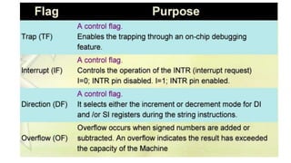
- 6. Functions of Segment Registers 1.Code segment (CS) register= The CS register holds the upper 16-bits of the starting address of the segment from which the BIU is currently fetching the instruction code byte. 2.stack segment (SS) register=The SS register is used for the upper 16-bits of the starting address for the program stack (all stack related instructions will operate on stack) 3.extra segment (ES) register= ES register and DS register are used to hold the upper 16-bits of the starting address of the two memory segments Which are used for data.
- 7. Execution Unit [EU]: • The execution unit of Internal Architecture of 8086 tells the BIU from where to fetch instructions or data, decodes instructions and executes instructions. It contains • Control Circuitry • Instruction Decoder • Arithmetic Logic Unit (ALU) • Flag Register • General Purpose Registers • Pointers and Index Registers
- 8. Execution Unit [EU]: • The control circuitry in the EU directs the internal operations. • A decoder in the EU translates the instructions fetched from memory into a series of actions wlifeh the EU performs. • ALU is 16-bit. It can add, subtract, AND, OR, XOR, increment, decrements, complement and shift binary numbers. • AX register: (Combination of AL and AH Registers) It holds operands and results during multiplication and division operations. Also an accumulator during String operations. • BX register: (Combination of BL and BH Registers) It holds the memory address (offset address) in indirect addressing modes. • CX register: (Combination of CL and CH Registers) It holds the count for instructions like a loop, rotates, shifts and string operations. • DX register: (Combination of DL and DH Registers) It is used with AX to hold 32-bit values during multiplication and division.
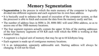
- 13. Memory Segmentation • Segmentation is the process in which the main memory of the computer is logically divided into different segments and each segment has its own base address. • It is basically used to enhance the speed of execution of the computer system, so that the processor is able to fetch and execute the data from the memory easily and fast. • The number of address lines in 8086 is 20, 8086 BIU will send 20bit address, so as to access one of the 1MB memory locations. • The four segment registers actually contain the upper 16 bits of the starting addresses of the four memory segments of 64 KB each with which the 8086 is working at that instant of time. • A segment is a logical unit of memory that may be up to 64 kilobytes long. • Each segment is made up of contiguous memory locations. • It is an independent, separately addressable unit. Starting address will always be changing. It will not be fixed.
- 14. Need for Segmentation • Code segment register (CS): is used for addressing memory location in the code segment of the memory, where the executable program is stored. • Data segment register (DS): points to the data segment of the memory where the data is stored. • Extra Segment Register (ES): also refers to a segment in the memory which is another data segment in the memory. • Stack Segment Register (SS): is used for addressing stack segment of the memory. The stack segment is that segment of memory which is used to store stack data.
- 16. Advantages of the Segmentation • It provides a powerful memory management mechanism. • Data related or stack related operations can be performed in different segments. • Code related operation can be done in separate code segments. • It allows to processes to easily share data. • It allows to extend the address ability of the processor, i.e. segmentation allows the use of 16 bit registers to give an addressing capability of 1 Megabytes. Without segmentation, it would require 20 bit registers. • It is possible to enhance the memory size of code data or stack segments beyond 64 KB by allotting more than one segment for each area.
- 17. Physical Memory Address Generation • One Mbyte (1024 Kbyte) of physical memory can be interface with the 8086 microprocessor because 8086 has 20 address lines i.e. 220 1024 Kbyte or 1 Mbyte • The segment registers are used to hold 16-bit of the starting address of four memory segments. • But 8086 has 20-bit address bus, so it can address any of 20= 1 Mbytes in memory • The address associated with any instruction or data byte is only 16-bit called as effective address or offset or displacement or logical address. • The logical addresses are used to calculate physical address.
- 18. stack pointer (SP) • The stack pointer (SP) register contains the 16-bit offset from the start of the segment to the top of stack. • For stack operation, physical address is produced by adding the contents of stack pointer register to the segment base address in SS. • To do this the contents of the stack segment register are shifted four bits left and the contents of SP are added to the shifted result. • If the contents of SP are 9F20H and SS are 4000H then the physical address is calculated as follows. • SS = 4000H after shifting four bits left SS = 40000H
- 19. Instruction Pointer IP • IP contains the offset address. • The result 20-bit address is the physical address since it is put on external physical address bus pins to be decoded by the memory decoding circuitry. • The offset address is contained in IP = 95F3 H. • the CS contained 2500 H. • The logical address is CS:IP or 2500:95F3. • The physical address will be 25000+ 95F3= 2E5F3 H
- 21. CONCEPTS OF THE PIPELINING • The technique used to enable an instruction to complete with each clock cycle is called as pipelining. • Normally, on a non-pipelined processor, nine clock cycles are required for fetch, decode and execute cycles for the three instructions • But, on a pipelined processor, the fetch, decode and execute operation are performed in parallel, only five clock cycles are required to execute the same three instructions • First instruction requires three cycles to complete the execution. • Next instructions then complete at a rate of one instruction per cycle. • During the clock cycle 5 we have I, completing, I, being decoded and Is being fetched • Stack is a reserved area of the memory in the RAM, where temporary information may be stored. • Stack operates on the principle of Last In First Out (LIFO).
- 22. • The queue operates on the principle of first in first out (FIFO). • So that the execution unit gets the instruction for execution in the order they fetched. • Feature of fetching the next instruction while the current instruction is executing is called pipelining which will reduce the execution time. • So. pipelining improve the execution speed of the processor. • In 8086, pipelining is implemented by providing 6 byte queue where as long as 6 one byte instructions can be stored well in a advance and then one by one instruction goes for decoding and execution. • So, while executing first instruction in a queue, processor decodes second instruction and fetches 8th instruction from the memory. • In this way, 8086 perform fetch, decode and execute operation in parallel i.e. in single clock cycle CONCEPTS OF THE PIPELINING
- 23. Advantages of Pipelining • Pipelining enables many instructions to be executed at the same time.It allows execution to be done in fewer cycles. • Speed up the execution speed of the processor. • More efficient use of processor.