INTRODUCTION TO ARDUINO and sensors for arduino.pptx
Download as PPTX, PDF0 likes61 views

The document provides an introduction to Arduino, describing it as an open-source prototype platform composed of hardware (a circuit board) and software (Arduino IDE) for programming. It explains key functions such as setup(), loop(), digitalwrite(), digitalread(), and analogread(), along with examples of sketch codes for various applications, including sensor usage. Additionally, it discusses the role of sensors in the physical environment and presents specific applications for soil moisture and water level sensors.


INTRODUCTION TO ARDUINO and sensors for arduino.pptx
- 1. INTRO TO ARDUINO Lorlie B. Andres, MECOE
- 2. ARDUINO Arduino is a prototype platform (open-source) based on an easy- to-use hardware and software. It consists of a circuit board, which can be programed (referred to as a microcontroller) and a ready-made software called Arduino IDE (Integrated Development Environment), which is used to write and upload the computer code to the physical board.
- 4. BOARD TYPES Arduino boards have one thing in common: they are programed through the Arduino IDE. The differences are based on the number of inputs and outputs (the number of sensors, LEDs, and buttons you can use on a single board), speed, operating voltage, form factor etc. Some boards are designed to be embedded and have no programming interface (hardware), which you would need to buy separately. Some can run directly from a 3.7V battery, others need at least 5V.
- 5. DIFFERENT COMPONENTS ON THE ARDUINO BOARD.
- 12. 3 MAIN PARTS OF ARDUINO PROGRAM Structure Values (variables and constants) Functions
- 13. TWO MAIN FUNCTIONS OF SOFTWARE STRUCTURE Setup( ) function The setup() function is called when a sketch starts. Use it to initialize the variables, pin modes, start using libraries, etc. The setup function will only run once, after each power up or reset of the Arduino board. Loop( ) function loop() function does precisely what its name suggests, and loops consecutively, allowing your program to change and respond. Use it to actively control the Arduino board.
- 14. Structure • Software structure consist of two main functions: • Setup( ) function • Loop( ) function
- 17. pinMode() function The pinMode() function is used to configure a specific pin to behave either as an input or an output. pinMode() Function Syntax pinMode (pin , mode); pin − the number of the pin whose mode you wish to set mode − INPUT, OUTPUT.
- 18. SAMPLE SKETCH int button = 5 ; // button connected to pin 5 int LED = 6; // LED connected to pin 6 void setup () { pinMode(button , INPUT); // set the digital pin as input pinMode(LED , OUTPUT); // set the digital pin as output }
- 19. digitalWrite() function the digitalWrite() function is used to write a HIGH or a LOW value to a digital pin. If the pin has been configured as an OUTPUT with pinMode(), its voltage will be set to the corresponding value: 5V (or 3.3V on 3.3V boards) for HIGH, 0V (ground) for LOW. If the pin is configured as an INPUT, digitalWrite() will enable (HIGH) or disable (LOW) the internal pullup on the input pin.
- 20. digitalWrite() function syntax Syntax: digitalWrite (pin ,value); Parameters: pin − the number of the pin whose mode you wish to set value − HIGH, or LOW.
- 21. SAMPLE SKETCH void loop () { If (digitalRead(button ) == LOW) // if button pressed { digitalWrite(LED,HIGH); // turn on led delay(500); // delay for 500 ms digitalWrite(LED,LOW); // turn off led delay(500); // delay for 500 ms } }
- 22. digitalRead() function digitalRead is used to read the status of any digital Pin in Arduino. Syntax digitalRead(pin) Parameters pin: the Arduino pin number you want to read Returns HIGH or LOW
- 23. SAMPLE SKETCH int button = 5 ; // button connected to pin 5 int LED = 6; // LED connected to pin 6 void setup () { pinMode(button , INPUT); // set the digital pin as input pinMode(LED , OUTPUT); // set the digital pin as output } void loop () { X=digitalRead(7); If (digitalRead(button ) == LOW) // if button pressed { digitalWrite(LED,HIGH); // turn on led delay(500); // delay for 500 ms digitalWrite(LED,LOW); // turn off led delay(500); // delay for 500 ms } }
- 24. analogRead( ) function Arduino is able to detect whether there is a voltage applied to one of its pins and report it through the digitalRead() function. There is a difference between an on/off sensor (which detects the presence of an object) and an analog sensor, whose value continuously changes. In the lower-right part of the Arduino board, you will see six pins marked “Analog In”. These special pins not only tell whether there is a voltage applied to them, but also its value. By using the analogRead() function, we can read the voltage applied to one of the pins. This function returns a number between 0 and 1023, which represents voltages between 0 and 5 volts. For example, if there is a voltage of 2.5 V applied to pin number 0, analogRead(0) returns 512
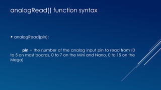
- 25. analogRead() function syntax analogRead(pin); pin − the number of the analog input pin to read from (0 to 5 on most boards, 0 to 7 on the Mini and Nano, 0 to 15 on the Mega)
- 26. SAMPLE SKETCH int analogPin = 3;//potentiometer wiper (middle terminal) // connected to analog pin 3 int val = 0; // variable to store the value read void setup() { Serial.begin(9600); // setup serial } void loop() { val = analogRead(analogPin); // read the input pin Serial.println(val); // debug value }
- 27. BLINKING LED It is as simple as turning a light on and off. Pin Configuration of LED
- 28. BLINKING LED CIRCUIT CONNECTION
- 29. SOURCE CODE int LED_OUTPUT_PIN = 3; void setup() { pinMode(LED_OUTPUT_PIN, OUTPUT); } void loop() { digitalWrite(LED_OUTPUT_PIN, HIGH); // turn LED on (output 5V) delay(1000); // wait one second digitalWrite(LED_OUTPUT_PIN, LOW); // turn LED off (output 0V) delay(1000); // wait another second }
- 31. WHAT IS A SENSOR? A sensor is a device that detects and responds to some type of input from the physical environment. The input can be light, heat, motion, moisture, pressure or any number of other environmental phenomena. The output is generally a signal that is converted to a human-readable display at the sensor location or transmitted electronically over a network for reading or further processing.
- 32. REAL TIME APPLICATION OF SENSORS (Autopilot System In Aircrafts)
- 34. CLASSIFICATION OF SENSOR Analog Sensors produce an analog output i.e., a continuous output signal (usually voltage but sometimes other quantities like Resistance etc.) with respect to the quantity being measured. Digital Sensors work with discrete or digital data. The data in digital sensors, which are used for conversion and transmission, is digital in nature.
- 35. SOIL MOISTURE SENSOR The Soil Moisture Sensor measures soil moisture grace to the changes in electrical conductivity of the earth ( soil resistance increases with drought ). The electrical resistance is measured between the two electrodes of the sensor. A comparator activates a digital output when a adjustable threshold is exceeded.
- 36. SOIL MOISTURE SENSOR CIRCUIT CONNECTION
- 37. ARDUINO SKETCH FOR SOIL MOISTURE SENSOR void setup() { Serial.begin(9600); pinMode(A0, INPUT); } void loop() { sensorValue = analogRead(A0); Serial.println("Analog Value : "); Serial.println(sensorValue);
- 38. WATER LEVEL SENSOR This sensor can be used to measure the water level, monitor a sump pit, detect rainfall or detect leakage. The series of exposed parallel conductors, together act as a variable resistor (just like a potentiometer) whose resistance varies according to the water level. The change in resistance corresponds to the distance from the top of the sensor to the surface of the water.
- 39. WATER LEVEL SENSOR CIRCUIT CONNECTION
- 40. ARDUINO SKETCH FOR WATER LEVEL SENSOR void setup() { pinMode(sensorPower, OUTPUT); digitalWrite(sensorPower, LOW); Serial.begin(9600); } void loop() { int level = readSensor(); Serial.print("Water level: "); Serial.println(level); }
- 41. FINAL ACTIVITY Develop an Arduino program that monitors the soil moisture level using a sensor. If the measured soil moisture falls below the threshold value of 25, the program should activate a LED and make it blink five times. Conversely, if the soil moisture reading is equal to or above 25, the LED should remain off.
- 42. THANK YOU AND GOD BLESS