SlideShare a Scribd company logo
IoT Programming on the
Raspberry Pi
Damien Magoni – University of Bordeaux
& Philip Perry – University College Dublin
2017/09/28
Version 4
Attribution
• The material contained inside is intended for teaching.
• This document is licensed under the CC BY-NC-SA license.
• All figures and text borrowed from external sources retain the rights
of their respective owners.
2
Table of Contents
1. IoT definition, facts and perspectives
• Sensors
• Edge nodes
2. Raspberry Pi operation
3. Raspberry Pi interfaces
• GPIO ports
4. DHT11 operation
5. Retrieving data from the DHT11 to the Raspberry Pi in Python
3
Internet of Things
Part 1
What is IoT?
• Internet of Things (IoT) is the networked connection of “things”
• Things are not humans – they are machines
• Usually sensors at the edge of the network measure real-world values
• These values may be shared with other edge nodes or, more often,
passed up through the network to some “intelligent” node
• This intelligent node may pass commands back down to the edges
5
6
Importance of IoT
• Health care - cost reduction and service quality improvement
• Energy – more efficient usage (management) and cost reduction
• City infrastructure – efficiency, costs, quality of life
• Security – automated, accessible from anywhere
• Industry – automated factories
• Agriculture – livestock and crop monitoring
7
8
IoT Perspectives – end users
• End users may only see a “service” that tells them something that
they want to know
• Is my home secure?
• Is the basement flooded?
• Is there parking available at work now? Where?
• What is the traffic like? What route should I take?
• Smart cities and infrastructure
• Monitoring electricity distribution system
• Heating control in buildings
• Emergency services management
9
IoT Perspectives – equipment providers
• Hardware manufacturers may provide sensors, actuators, low power
edge nodes, networking equipment, servers
• Edge nodes can be simple or complex
• Raspberry Pi – multi-core processor with dedicated Input/Output (I/O) pins
• Arduino – microcontroller with dedicated peripherals
• Dedicated chips that simply sample data and pass them up the network
• The edge network is often wireless – WiFi, Bluetooth etc
• As we move closer to the core of the network, routers need to carry
more traffic – along with regular Internet traffic
10
IoT Perspectives - service providers
• Services may be deployed locally or in the cloud
• Smart watch sending heartrate to a smart phone. Timestamped and
geo-tagged data sent to cloud for well-being monitoring.
• Health monitoring for diabetes or heart conditions
• Smart cities monitoring services
• Or maybe a platform that you can build your own service – IBM
Watson or Microsoft Azure
• Some services provide the edge nodes and the central intelligence
11
IoT Growth
12
IoT Market Size
13
What is a Sensor?
• A device that measures a physical quantity
• The values measured by a sensor may be
• Analogue – a continuous variable such as temperature
• Binary – yes/no, on/off, high/low, wet/dry, hot/cold
• Quantised – usually a version of a continuous variable with a finite number of
discrete possible values, eg 0.0, 0.1, 0.2, 0.3 etc, or Cold/Warm/Hot
• Digital – a quantised value that is captured at some point in time (depending
on the sampling frequency)
• Internet can only send/receive digital data
14
Types of Sensors
• Voltage, current, phase, power
• Temperature, humidity,
atmospheric pressure, wind
speed
• Heart rate, respiratory rate,
blood pressure, body
temperature
• Volume of traffic (cars), speed,
parking spaces
15
What is an Edge Node?
• The edge node is the last node that can communicate using the
Internet Protocol (IP)
• It is connected to a network by using a layer 2 technology such as
• Ethernet (wired, needs a switch)
• WiFi (wireless, needs an access point)
• Bluetooth
• Cellular (needs a SIM card slot)
16
Types of Edge Nodes
• Microcontroller-based (e.g.
Arduino, Galileo, etc.)
• Simple processor on a board with
I/O pins
• Single thread
• Microprocessor-based (e.g. Pi,
Odroid, Beagle, etc.)
• Often based on low power
consumption processors (eg. ARM)
• Linux OS
• Multi-threading introduces non-
real-time OS issues
17
Central Processing Unit (CPU)
• A CPU is the electronic circuitry within a computer that carries out
the instructions of a computer program by performing the basic
arithmetic, logical, control and input/output (I/O) operations
specified by the instructions
• The term CPU refers to a processor (more specifically to its processing
unit (ALU) and control unit), distinguishing it from external
components such as main memory and I/O circuitry
• Most modern CPUs are microprocessors, meaning they are contained
on a single integrated circuit chip
18
Microprocessors
• A microprocessor is a computer processor which incorporates the
functions of a computer's CPU on a single integrated circuit (IC)
• The microprocessor is a multipurpose, clock driven, register based,
digital IC which accepts binary data as input, processes it according to
instructions stored in its memory, and provides results as output
• They are used in personal computers or other general purpose
applications consisting of various discrete chips (CPU, memory, I/O
bridge, DSP, etc.)
19
Microcontrollers
• A microcontroller is a small computer on a single integrated circuit
• A microcontroller contains one or more CPUs along with memory and
programmable I/O peripherals
• Program (non-volatile) memory and some RAM is often included on chip
• Designed for embedded applications
• Must provide real-time (predictable) response to events in the embedded
system they are controlling
• When certain events occur, an interrupt system can signal the processor to
suspend processing the current instruction sequence and to begin an
interrupt service routine
20
Single Board Microcontroller
• A single-board microcontroller is a microcontroller built onto a single
printed circuit board (e.g., Arduino)
• This board provides all of the circuitry necessary for a useful control task
• Microprocessor, I/O circuits, clock generator, RAM, stored program memory, etc.
• A single-board microcontroller differs from a single-board computer (e.g.,
Raspberry Pi) in that it lacks the general-purpose user interface and mass
storage interfaces that a more general-purpose computer would have
• Compared to a microprocessor development board, a microcontroller
board would emphasize digital and analog control interconnections to
some controlled system, whereas a development board might by have only
a few digital or analog input/output devices
21
System-on-Chip (SoC)
• A SoC is an integrated circuit that integrates all components of a
computer or other electronic systems (e.g. Broadcom 283x)
• It integrates a microcontroller (or microprocessor) with advanced
peripherals like graphics processing unit (GPU), Wi-Fi module, or
coprocessor
• It may contain digital, analog, mixed-signal, and often radio-frequency
functions—all on a single substrate
• A typical application is in the area of embedded systems
22
Raspberry Pi Operation
Part 2
Raspberry Pi Model B Version 3
• Broadcom BCM2837 SoC -
Architecture ARMv8-A (64/32-bit)
• Quad core CPU ARM Cortex-A53 64-
bit running at 1.2GHz
• 1GB RAM (900MHz) + Micro SDHC
card slot (up to 32GB)
• Built in 10/100 Mbps Ethernet, 4x USB
ports, WiFi 802.11n and Bluetooth 4.1
• General Purpose Input/Output (GPIO)
pins, serial UART, I2C bus, SPI bus
• Power rating 300 mA (1.5 W) average
when idle, 1.34 A (6.7 W) maximum
24
Powering the Pi
• Many problems with the Raspberry Pi can be traced to an inadequate
power supply
• Model A draws up to 500 mA, RPi 3 can draw up to 1.3 A
• Not all USB power adapters are designed to offer this much power
• The USB standard states that devices should draw no more than 500 mA
• with even that level of power available only to the device following a process called
negotiation
• The Pi doesn’t negotiate for power, which can cause problems when trying
to power the Pi from a PC’s USB port
• While lower-power models such as the Pi Zero may work, higher-power
models like the Pi 2 and 3 should never be powered from a PC’s USB port
25
Checking the Power
• The power LED of the Pi acts as an in-built voltage test
• If the power LED is flashing or unlit, the power supply is providing less
than 4.65 V (below the 5 V USB standard) and should be replaced
• To check the power your Pi is receiving, use a USB power meter (a
form of multimeter) designed to sit in-between the USB power supply
and the Pi and measure the voltage and amperage
• The voltage reading on the USB power meter should be between 4.65
V and 5.2 V
26
Raspberry Pi Operating System
• Raspbian is the official OS, based on the Debian Linux distribution
• Also available: Ubuntu, Windows 10 IoT, OSMC, etc.
• Choose and download from here
www.raspberrypi.org/downloads
• Unzip the file and make a block copy on a FAT32 SD card
sudo dd bs=4m if=/home/user/2017-09-07-raspbian-stretch.img of=/dev/sd[x]
(or /dev/mmcblk[x])
27
RPi Boot Process
• No BIOS or battery backed
memory by default
• Uses specific, efficient but closed
source bootloaders developed
by Broadcom
• Bootloaders and configuration
files are located in the /boot
directory of the RPi image
28
Boot Diagnostics
• Common cause for a Pi to fail to boot is a problem with the SD card
• The Pi relies on files stored on the SD card for everything
• If the Pi can’t talk to the card, it won’t display anything on the screen or
show any signs of life at all
• If the Pi’s PWR light glows when you connect the power supply but nothing
else happens and the ACT (activity) light isn’t flickering to indicate data
access, there is an SD card problem
• Ensure that the card works when connected to a PC and that it shows the
partitions and files expected of a well-flashed card
• If the card works on a PC but not on the Pi, it may be a compatibility
problem
29
User Accounts
• By default, Raspbian is configured with two user accounts
• pi: normal user account (password raspberry)
• root: superuser / administrator account with additional permissions
• Raspbian by default is configured so that the root account can't be
logged into using a password
• Use sudo command instead
30
RPi Configuration
• The primary configuration file for the RPi is /boot/config.txt
• Configure Raspbian with
sudo raspi-config
• Changes made using the raspi-config tool are reflected in this file
• You can manually edit this file to enable/disable bus hardware, overclock
the processors, etc.
sudo nano /boot/config.txt
• Another file /boot/cmdline.txt is for passing arguments (e.g., tty
params, rootfs type, etc.) to the Linux kernel on boot
sudo nano /boot/cmdline.txt
31
Useful Raspbian Linux Commands
• Start the GUI desktop
startx
• Update the system
sudo apt-get update
sudo apt-get upgrade
sudo apt-get install <package-name>
• Shutdown the system
sudo shutdown –h now
32
Configure the Wired Network
• Check with ifconfig
• Disable and re-enable network
interface
• sudo ifdown eth0
• sudo ifup eth0
• Configure a connection by
editing /etc/dhcpcd.conf
• Add lines
interface eth0
static ip_address=192.168.0.13
static routers=192.168.0.254
static domain_name_servers=8.8.8.8
8.8.4.4
static domain_search=local
• Restart the network stack
sudo service networking restart
33
Configure the Wireless Network
• scan for nearby wireless access
points
sudo iwlist scan | less
• Check network interface
iwconfig wlan0
• Use wpasupplicant to connect
the Pi to almost any wireless
network (WPA, WPA2)
• Edit the configuration file
sudo nano
/etc/wpa_supplicant/wpa_supplicant.conf
• Add lines
network={
[Tab] ssid="Your_SSID"
[Tab] key_mgmt=WPA-PSK
[Tab] psk="Your_WPA_Key"
}
• Restart interface
ifup wlan0
34
Connecting to the RPi using the Network
• Show IP address
ip addr
• Connect using a CLI with SSH
ssh pi@192.168.0.111
• Connect using a GUI with VNC
sudo apt-get install tightvncserver
• When the server starts, it will tell you which virtual desktop has
been started. This will normally be session 1
New 'X' desktop is raspberrypi:1
• On the client, indicate the remote host as
192.168.0.111:1
35
Zeroconf Networking
• Avahi is a free zero-configuration
networking (zeroconf)
implementation, including a system
for multicast DNS/DNS-SD service
discovery
• Avahi enables programs to publish
and discover services and hosts
running on a local network
• A user can plug a computer into a
network and have Avahi
automatically advertise the
network services running on the
machine which could enable access
to files and printers
• On the RPi
sudo apt-get install avahi-daemon
• On the remote machine
ssh pi@raspberrypi.local
36
Bluetooth Connection
• Switch your Bluetooth device on and activate pairing mode
• Typically involves holding down a button or key, see device’s documentation
• With the device in pairing mode, click the Bluetooth icon on the
Raspbian taskbar (near the clock at the right edge of the screen)
• Click on Add Device to launch the Add New Device menu
• Find your chosen device in the list, and then click Pair
• The Pi will launch the pairing procedure (differs from device to
device), follow onscreen instructions to pair the two devices together
37
Raspberry Pi Interfaces
Part 3
Raspberry Pi GPIO Ports
• GPIO stands for General Purpose Input Output
• It is a term used to refer to ports that can be used either as inputs or
outputs
• The GPIO pins on the Raspberry Pi are connected directly to the GPIO
ports on the processor
• The processor runs at 3.3V and as such the GPIO ports are designed
for 3.3V
• The GPIO ports do not include any built-in protection!!
• Giving an input that is above 3.3V, or drawing too much current from
an output, can permanently damage the Raspberry Pi!!
39
Raspberry Pi 3 Pinout
40
+5V from the Raspberry Pi GPIO
• The 5V connection on the GPIO connector is a fixed 5V power supply
that can be used to power a low-power circuit from the Raspberry Pi
• It is possible to connect an external 5V supply to that pin and use that
to power the Raspberry Pi
• The amount of current that can be taken from this supply is limited
but it could be used to power low-power electronic circuits
• Do not shorten accidentally one of those 5V pins 2 and 4 with any
other GPIO pins or you will damage the SoC!!
41
Default GPIO Pins
• The GPIO port provides at least eight pins for general-purpose use by
default: Pin 7, Pin 11, Pin 12, Pin 13, Pin 15, Pin 16, Pin 18, and Pin 22
• These pins can be toggled between three states: high, where they are
providing a positive voltage of 3.3 V; low, where they are equal to ground
or 0 V; and input
• The two outputs equate to the 1 and 0 of binary logic and can be used to
turn other components on or off
• The GPIO port has pins dedicated to particular buses
• Pi’s internal logic operates at 3.3 V, in contrast to many microcontroller
devices (e.g., Arduino), which typically operate at 5 V!!
• Devices designed for the Arduino may not work with the Pi unless a level
translator or optical isolator is used between the two
42
Universal Asynchronous Receiver/Transmitter
(UART) Serial Bus
• UART serial bus provides a simple two-wire serial interface
• When a serial port is configured in the cmdline.txt file, this serial bus is
used as the port for the messages
• Connecting the Pi’s UART serial bus to a device capable of displaying the data
reveals messages from the Linux kernel
• The UART serial bus can be accessed on Pins 8 and 10, with Pin 8
carrying the transmit signal and Pin 10 carrying the receive signal
(speed is set in cmdline.txt at 115,200 bps)
43
Inter-Integrated Circuit (I2C) Bus
• I2C bus is designed to provide communications between multiple
integrated circuits (ICs)
• In the Pi, this bus connects to the Broadcom BCM2835 SoC processor
• These pins are connected to pull-up resistors located on the Pi, meaning no external
resistors are required to access the I2C functionality
• The I2C bus can be accessed on Pins 3 and 5, with Pin 3 providing the Serial
Data Line (SDA) signal and Pin 5 providing the Serial Clock Line (SCL) signal
• The I2C bus available on these pins is actually only one of two provided by
the BCM2835 chip (bus 1 on RPi 3)
• The second I2C bus is reserved for use by the Pi Camera Module and Touchscreen
Display
44
Serial Peripheral Interface (SPI) Bus
• SPI is a synchronous serial bus that offers improved performance compared
with I2C
• SPI is a four-wire bus with multiple Chip Select lines, which allow it to
communicate with more than one target device
• The Pi’s SPI bus is available on Pins 19, 21, and 23, with a pair of Chip Select
lines on Pin 24 and Pin 26
• Pin 19 provides the SPI Master Output, Slave Input (MOSI) signal
• Pin 21 provides the SPI Master Input, Slave Output (MISO) signal
• Pin 23 provides the Serial Clock (SLCK) used to synchronise communication
• Pins 24 and 26 provide the Chip Select signals for up to two independent
slave devices
45
1-Wire
• The 1-Wire interface is another alternative to I2C and SPI, offering
connectivity to and communication with sensors and other external
hardware
• Typically, 1-Wire is used to connect simple sensors—such as devices
for reading the temperature or humidity of the environment—to the
Raspberry Pi, and is rarely used by add-on boards
46
Add-On Hardware
• 100s of compatible add-on devices which connect through the
multifunction GPIO header
• Add-on boards for RPis are called Hardware Attached on Top (HAT) and
should follow the HAT standard to ensure compatibility
• The standard covers both the physical and electrical design of the add-on
board
• The board must attach to the 40-pin GPIO header and include mounting holes that
line up with those on the Pi Model B+ and newer. It must also be rectangular,
measuring 65 mm by 56 mm
• EEPROM module on the board which contains information about how the board
works, how the Pi’s GPIO pins are used, and a device tree for setting the board up
within the operating system
47
Sense HAT
• Multifunction I/O board designed
for use in the Astro Pi programme
(orbiting the Earth as part of a
science bundle sent up to the ISS)
• Onboard sensors provide board’s
orientation and position via a
gyroscope, accelerometer,
magnetometer, ambient air
pressure, temperature, and
humidity levels
• Onboard 8x8 matrix of LEDs
provides an output, and interaction
is possible through the use of the
Sense HAT’s five-way joystick
48
Pi Camera Module v2
• Connect to the Camera Serial
Interface (CSI)
• Measures 25 mm on its longest
edge and weighs 3 g
• 8Mpx sensor, fixed-focus lens
• Full HD video capture, 30 fps
• NoIR version without IP filter
(needs external IR LEDs)
• H.264 hardware acceleration
49
Using the Camera
• Install the frame buffer image viewer
sudo apt-get install fbi
• View images using the tool
fbi -a imagename.jpg
• Still image capture with raspistill as JPEG (-e for other formats)
• raspistill -o testcapture.jpg
• Video capture (size in px, duration in ms) with raspivid as H.264
raspivid –t 60000 -w 1280 -h 720 -o hdvideo.h264
50
Digital Humidity & Temperature
Sensor/Module
Part 4
DHT11 Temperature and Humidity Sensor
• Measure humidity and temperature of the surrounding environment
• Humidity measurement range : 20% ~95%
• Humidity measurement error : ±5%
• Temperature measurement range : 0℃~50℃
• Temperature measurement error : ±2 ℃
• Operating voltage : 3.3 V~5 V
• Digital output form
• PCB Dimension: 32 mm x 14 mm
52
DHT11 Sensor Pinout
• Left-to-right
• Pin 1: VCC
• Pin 2: DATA
• Pin 3: null
• Pin 4: GND
53
Power and Interconnection
• DHT11’s power supply is 3 to
5.5V DC
• When power is supplied to the
sensor, do not send any
instruction to the sensor in
within 1 second in order to pass
the unstable status
• MCU = µcontroller unit
54
DHT11 Module Pinout
• Sensor soldered on PCB
• Left-to-right
• Pin 1: VCC (V)
• Pin 2: DATA (S)
• Pin 3: GND (G)
55
Jumper Wires
• Dupont Cable
• 10cm length
• 2.54mm pin width
• 1 pin female to female for
arduino/raspberry pi
56
Communication Process
• Serial Interface (Single-Wire Two-Way)
• Single-bus data format is used for communication and
synchronization between MCU and DHT11 sensor
• One communication process is about 4ms
• Data consists of decimal and integral parts
• A complete data transmission is 40bit, and the sensor sends higher
data bit first
• The sensor can be queried once per second maxi
57
Data Format and Checksum
• The data is transmitted in this format: 8bit integral RH data + 8bit
decimal RH data + 8bit integral T data + 8bit decimal T data + 8bit
check sum
• If the data transmission is correct, the check sum should be equal to
the lower 8bit of the result of (8bit integral RH data + 8bit decimal RH
data + 8bit integral T data + 8bit decimal T data)
58
Overall Communication Process
• When MCU (black) sends a start signal, DHT11 (green) changes from the
low-power-consumption mode to the running-mode, waiting for MCU
completing the start signal
• Once it is completed, DHT11 sends a response signal of 40-bit data to MCU
• Without the start signal from MCU, DHT11 will not reply
• Once data is collected, DHT11 will change to the low-power-consumption
mode until it receives a start signal from MCU again
59
MCU Sends out Start Signal to DHT
• The default status of the DATA pin is high-voltage level
• When the communication between MCU (black) and DHT11 (green) starts,
MCU will pull down the DATA pin for 18ms, this is called Start Signal, to
ensure DHT11 has detected the signal
• Then MCU will pull up DATA pin for 20-40µs to wait for DHT11’s response
60
DHT Response Signal to MCU
• Once the DHT detects the start signal, it will send out a low-voltage
level response signal, which lasts 80µs
• Then the DHT sets the voltage level from low to high and keeps it for
80µs, and prepares for data transmission
61
Data « 0 » Indication
• When DHT is sending data to MCU, every bit of data begins with the
50µs low-voltage-level and the length of the following high-voltage-
level signal determines whether data bit is "0" or "1“
• Data bit “0” has 26-28µs high-voltage length
62
Data « 1 » Indication
• Data bit “1” has 70µs high-voltage length
• When the last bit data is transmitted, DHT11 pulls down the voltage level and
keeps it for 50µs
• Then the voltage will be pulled up by the resistor to set it back to the free status
• If the response signal from DHT is always at high-voltage-level, the DHT is not
responding properly, check the connection
63
Retrieving Data from the DHT11
to the Raspberry Pi
Part 5
The Design Process in a Nutshell
• Designing a circuit is a multi-step process
1. Start with the idea
2. Research the available components,
3. Design it into a circuit showing how components will be connected
4. Prototype the circuit by making a temporary circuit before creating the final
finished one
• The final circuit could be built on an off-the-shelf board such as
stripboard or made into a complete printed circuit board, depending
on your budget and the complexity of the circuit
65
An Iterative Process
• Each of these stages can be repeated as necessary until you come to
the final design
• As you move through the stages, the potential cost increases both in
terms of money and the time
• The earlier you identify any potential problems the less it will cost
• Don’t be afraid to go back to the start rather than trying to continue
with a design that isn’t working
66
Electronic Equipment
• An electronic breadboard provides a grid of holes spaced at 2.54 mm
intervals into which components can be inserted and removed
• Below each grid is a series of electrical contacts which allow
components in the same row to be connected together without wires
• Jumper wires are used to connect one row to another, or to connect
the breadboard to the Pi’s GPIO port (use solid-core wire rather than
stranded-core wire)
• Stripboard is a single-use breadboard where components need to be
soldered into place making a permanent electronic circuit
67
Resistors
• A resistor is a passive two-
terminal electrical component
that implements electrical
resistance as a circuit element
• Resistors are measured in ohms,
written as the symbol Ω
• Resistance value in ohms is
calculated from the color bands
that adorn the resistor’s surface
68
Raspberry Pi 2/3 40-pin I/Os
• Hardware interfaces for the Raspberry Pi 3 are exposed through the
40-pin header J8 on the board
• 24x - GPIO pins
• 1x - Serial UARTs (RPi3 only includes mini UART) + 2x - SPI bus + 1x - I2C bus
• 2x - 5V power pins + 2x - 3.3V power pins + 8x - Ground pins
69
Connections with GPIOs on RPi3
Raspberry Pi DHT11 Module
3.3v P1 P1 VCC (V)
GND P6 P3 GND (G)
GPIO4 (GPCLK0) P7 P2 DATA (S)
70
RPi.GPIO Python Library
• This package provides a python class to control the GPIO pins on a RPi
• This module is unsuitable for real-time or timing critical applications
• It can not be predicted when Python will be busy garbage collecting
• It also runs under the Linux kernel which is not suitable for real time applications as it is
multitasking O/S and another process may be given priority over the CPU, causing jitter
in your program
• For true real-time performance and predictability, use a µcontroller (e.g., Arduino)
https://pypi.python.org/pypi/RPi.GPIO
• The package’s documentation is here
https://sourceforge.net/p/raspberry-gpio-python/wiki/Examples/
71
RPIO Python Library
• RPIO.py extends RPi.GPIO and uses the BCM GPIO numbering scheme by
default
• https://pythonhosted.org/RPIO/
• GPIO interrupts with debouncing
• Interrupts are used to receive notifications from the kernel when GPIO state changes
occur
• If debounce_timeout_ms is set, interrupt callbacks will not be started until the
specified milliseconds have passed since the last interrupt
• Minimized cpu consumption, fast notification times, ability to trigger on specific edge
transitions (rising, falling or both)
• TCP socket interrupts
• GPIO input & output
• Hardware PWM
72
Initialisation and Data Collecting Code
import RPi.GPIO as GPIO
import time
def bin2dec(string_num):
return str(int(string_num, 2))
data = []
# BCM numbering system
GPIO.setmode(GPIO.BCM)
GPIO.setup(4,GPIO.OUT)
GPIO.output(4,GPIO.HIGH)
time.sleep(0.025) #25ms
# 20ms start signal
GPIO.output(4,GPIO.LOW)
time.sleep(0.02)
# set input pin to high level
GPIO.setup(4, GPIO.IN,
pull_up_down=GPIO.PUD_UP)
# polling DHT 500x
for i in range(0,500):
# read binary data from DHT
data.append(GPIO.input(4))
# variables initialisation
count = 0
bit_count = 0
HumidityBits = ""
TemperatureBits = ""
crc = ""
73
Reading the Values from the Data
try:
..# skip all first 1’s (DHT response)
while data[count] == 1:
....count = count + 1
# read first 32 bits
for i in range(0, 32):
bit_count = 0
# skip 0’s
while data[count] == 0:
......count = count + 1
....# read 1’s
while data[count] == 1:
......bit_count = bit_count + 1
count = count + 1
if bit_count>3: #if 1’s length is>3(70µs)
if i>=0 and i<8: #read integral H part
........HumidityBits = HumidityBits + "1"
if i>=16 and i<24: #read integral T part
TemperatureBits = TemperatureBits + "1"
else: #if 1’s length is<4(27µs)
if i>=0 and i<8:
HumidityBits = HumidityBits + "0"
if i>=16 and i<24:
TemperatureBits = TemperatureBits + "0“
except:
print "ERR_DATA_READ"
exit(0)
74
Checking CRC and Printing Results
# read last 8 bits for the CRC
try:
..for i in range(0, 8):
....bit_count = 0
while data[count] == 0:
......count = count + 1
while data[count] == 1:
bit_count = bit_count + 1
count = count + 1
if bit_count > 3:
crc = crc + "1"
else:
crc = crc + "0"
except:
print "ERR_CRC_READ"
exit(0)
# convert binary strings to decimal
Humidity = bin2dec(HumidityBits)
Temperature = bin2dec(TemperatureBits)
# check CRC and print
if (int(Humidity) + int(Temperature) –
int(bin2dec(crc)) == 0):
print "Humidity:"+ Humidity +"%"
print "Temperature:"+ Temperature +"C"
else:
print "ERR_CRC_CALC"
exit(0)
75
Comments
• Reading 500 samples is arbitrary
• Reading up to three 1’s for defining
a 0 and more for defining a 1 is
arbitrary
• Your mileage may vary -> see post on
the right
• Print the data[ ] array to see the
signals
• Should we skip the first 0’s?
• The CRC computation is wrong
• Why? Correct it
• Use interruptions instead of polling
• “I discovered the following:
• - a "0" data/crc bit is a row of 7-8
consecutive '1' samples
• - a "1" data/crc bit is a row of 21-22
consecutive '1' samples
• I changed the trigger to 13
consecutive samples : below, it's a
0 and above, it's a 1
• Obviously, I need far more samples
(avg 1050-1150) so I take 1300, just
to make sure”
76
References
• Original source code
• Provides also (much better) C code (with correct checksum  )
http://www.uugear.com/portfolio/dht11-humidity-
temperature-sensor-module/
• Advanced code for the DHT22
• Uses another library (pigpio) with callbacks
https://www.raspberrypi.org/forums/viewtopic.php?p=51557
5#p515575
77
Using AdaFruit API
import Adafruit_DHT
sensor = 11
pin = 27
while True:
humidity, temperature = Adafruit_DHT.read_retry(sensor, pin)
# GPIO27 (BCM notation)
print("Humidity={}%; Temperature={}C".format(humidity, temperature))
• Adafruit tutorial
https://learn.adafruit.com/dht-humidity-sensing-on-raspberry-pi-with-gdocs-
logging/wiring
• Daskal Tutorial
http://invent.module143.com/daskal_tutorial/raspberry-pi-3-gpio-dht11-
digital-temperature-humidity-sensor/
78
WiringPi C Library
• WiringPi is a PIN based GPIO access library written in C for the
BCM2835 used in the Raspberry Pi
• Released under the GNU LGPLv3 license
• Usable from C, C++ and RTB (BASIC), the documentation is here
http://wiringpi.com/
• The C library is here
https://git.drogon.net/
• Python wrappers are here
https://github.com/WiringPi/WiringPi-Python
79
Running a Program as a Service
• On Raspbian, the startup and running processes are controlled using
systemd
• To register the program as a service, you need a special service file stored
in the /etc/systemd/system/ directory; it must end with the suffix
.service and needs to be created as the root user using sudo
sudo vi /etc/systemd/system/dht11.service
• To start the service
sudo systemctl start dht11
• To stop the service
sudo systemctl stop dht11
80
Service File Content
[Unit]
Description=DHT11 control program
[Service]
Type=simple
ExecStart=/usr/bin/python3 /home/pi/dht11/dht11.py
User=pi
[Install]
WantedBy=default.target
81
Ad

More Related Content

What's hot (20)

Ins and Outs of GPIO Programming
Ins and Outs of GPIO ProgrammingIns and Outs of GPIO Programming
Ins and Outs of GPIO Programming
ICS
 
ARDUINO AND ITS PIN CONFIGURATION
 ARDUINO AND ITS PIN  CONFIGURATION ARDUINO AND ITS PIN  CONFIGURATION
ARDUINO AND ITS PIN CONFIGURATION
soma saikiran
 
ARM Processor
ARM ProcessorARM Processor
ARM Processor
Aniket Thakur
 
8085 microprocessor ramesh gaonkar
8085 microprocessor   ramesh gaonkar8085 microprocessor   ramesh gaonkar
8085 microprocessor ramesh gaonkar
Manzoor ALam
 
6lowpan
6lowpan6lowpan
6lowpan
Dwarakanath Tulasi
 
IoT Arduino UNO, RaspberryPi with Python, RaspberryPi Programming using Pytho...
IoT Arduino UNO, RaspberryPi with Python, RaspberryPi Programming using Pytho...IoT Arduino UNO, RaspberryPi with Python, RaspberryPi Programming using Pytho...
IoT Arduino UNO, RaspberryPi with Python, RaspberryPi Programming using Pytho...
Jayanthi Kannan MK
 
Instruction Set Architecture (ISA)
Instruction Set Architecture (ISA)Instruction Set Architecture (ISA)
Instruction Set Architecture (ISA)
Gaditek
 
Complex Programmable Logic Device (CPLD) Architecture and Its Applications
Complex Programmable Logic Device (CPLD) Architecture and Its ApplicationsComplex Programmable Logic Device (CPLD) Architecture and Its Applications
Complex Programmable Logic Device (CPLD) Architecture and Its Applications
elprocus
 
I2C Protocol
I2C ProtocolI2C Protocol
I2C Protocol
Sudhanshu Janwadkar
 
Embedded Systems
Embedded SystemsEmbedded Systems
Embedded Systems
Navin Kumar
 
Embedded Systems - Training ppt
Embedded Systems - Training pptEmbedded Systems - Training ppt
Embedded Systems - Training ppt
Nishant Kayal
 
TCP and UDP
TCP and UDP TCP and UDP
TCP and UDP
Ramesh Giri
 
Ppt on embedded systems
Ppt on embedded systemsPpt on embedded systems
Ppt on embedded systems
Vaibhava Mishra
 
Fpga architectures and applications
Fpga architectures and applicationsFpga architectures and applications
Fpga architectures and applications
Sudhanshu Janwadkar
 
Analog to Digital converter in ARM
Analog to Digital converter in ARMAnalog to Digital converter in ARM
Analog to Digital converter in ARM
Aarav Soni
 
Embedded System Basics
Embedded System BasicsEmbedded System Basics
Embedded System Basics
Dr M Muruganandam Masilamani
 
Computer system organization
Computer system organizationComputer system organization
Computer system organization
Syed Zaid Irshad
 
Unit II Arm 7 Introduction
Unit II Arm 7 IntroductionUnit II Arm 7 Introduction
Unit II Arm 7 Introduction
Dr. Pankaj Zope
 
ESP32 IoT presentation @ dev.bg
ESP32 IoT presentation @ dev.bgESP32 IoT presentation @ dev.bg
ESP32 IoT presentation @ dev.bg
Martin Harizanov
 
Embedded system and its platforms
Embedded system and its platformsEmbedded system and its platforms
Embedded system and its platforms
Mrunal Deshkar
 
Ins and Outs of GPIO Programming
Ins and Outs of GPIO ProgrammingIns and Outs of GPIO Programming
Ins and Outs of GPIO Programming
ICS
 
ARDUINO AND ITS PIN CONFIGURATION
 ARDUINO AND ITS PIN  CONFIGURATION ARDUINO AND ITS PIN  CONFIGURATION
ARDUINO AND ITS PIN CONFIGURATION
soma saikiran
 
8085 microprocessor ramesh gaonkar
8085 microprocessor   ramesh gaonkar8085 microprocessor   ramesh gaonkar
8085 microprocessor ramesh gaonkar
Manzoor ALam
 
IoT Arduino UNO, RaspberryPi with Python, RaspberryPi Programming using Pytho...
IoT Arduino UNO, RaspberryPi with Python, RaspberryPi Programming using Pytho...IoT Arduino UNO, RaspberryPi with Python, RaspberryPi Programming using Pytho...
IoT Arduino UNO, RaspberryPi with Python, RaspberryPi Programming using Pytho...
Jayanthi Kannan MK
 
Instruction Set Architecture (ISA)
Instruction Set Architecture (ISA)Instruction Set Architecture (ISA)
Instruction Set Architecture (ISA)
Gaditek
 
Complex Programmable Logic Device (CPLD) Architecture and Its Applications
Complex Programmable Logic Device (CPLD) Architecture and Its ApplicationsComplex Programmable Logic Device (CPLD) Architecture and Its Applications
Complex Programmable Logic Device (CPLD) Architecture and Its Applications
elprocus
 
Embedded Systems
Embedded SystemsEmbedded Systems
Embedded Systems
Navin Kumar
 
Embedded Systems - Training ppt
Embedded Systems - Training pptEmbedded Systems - Training ppt
Embedded Systems - Training ppt
Nishant Kayal
 
Fpga architectures and applications
Fpga architectures and applicationsFpga architectures and applications
Fpga architectures and applications
Sudhanshu Janwadkar
 
Analog to Digital converter in ARM
Analog to Digital converter in ARMAnalog to Digital converter in ARM
Analog to Digital converter in ARM
Aarav Soni
 
Computer system organization
Computer system organizationComputer system organization
Computer system organization
Syed Zaid Irshad
 
Unit II Arm 7 Introduction
Unit II Arm 7 IntroductionUnit II Arm 7 Introduction
Unit II Arm 7 Introduction
Dr. Pankaj Zope
 
ESP32 IoT presentation @ dev.bg
ESP32 IoT presentation @ dev.bgESP32 IoT presentation @ dev.bg
ESP32 IoT presentation @ dev.bg
Martin Harizanov
 
Embedded system and its platforms
Embedded system and its platformsEmbedded system and its platforms
Embedded system and its platforms
Mrunal Deshkar
 

Similar to IoT Programming on the Raspberry Pi (20)

System unit and ip cycle
System unit and ip cycleSystem unit and ip cycle
System unit and ip cycle
Atif Nauman
 
Embedded systems الانظمة المدمجة
Embedded systems  الانظمة المدمجة Embedded systems  الانظمة المدمجة
Embedded systems الانظمة المدمجة
salih mahmod
 
IoT Unit-gsgsgsgasgGwaczxvxbxbbhhhh2.pptx
IoT Unit-gsgsgsgasgGwaczxvxbxbbhhhh2.pptxIoT Unit-gsgsgsgasgGwaczxvxbxbbhhhh2.pptx
IoT Unit-gsgsgsgasgGwaczxvxbxbbhhhh2.pptx
rajukolluri
 
Null mumbai-iot-workshop
Null mumbai-iot-workshopNull mumbai-iot-workshop
Null mumbai-iot-workshop
Nitesh Malviya
 
Internet of things
Internet of thingsInternet of things
Internet of things
Brockanurag
 
Rasberry pie--- power point presentation
Rasberry pie--- power point presentationRasberry pie--- power point presentation
Rasberry pie--- power point presentation
trangasaivarun
 
21PSP13
21PSP1321PSP13
21PSP13
sweetheartshridevi
 
M.Tech Internet of Things Unit - III.pptx
M.Tech Internet of Things Unit - III.pptxM.Tech Internet of Things Unit - III.pptx
M.Tech Internet of Things Unit - III.pptx
AvinashAvuthu2
 
Embedded Systems and Arduino Architecture
Embedded Systems and Arduino ArchitectureEmbedded Systems and Arduino Architecture
Embedded Systems and Arduino Architecture
ATHIRAMENONMS
 
Embedded Systems and Arduino Architecture
Embedded Systems and Arduino ArchitectureEmbedded Systems and Arduino Architecture
Embedded Systems and Arduino Architecture
ATHIRAMENONMS
 
Hardware and networking detailed ppt
Hardware and networking detailed pptHardware and networking detailed ppt
Hardware and networking detailed ppt
IICT Chromepet
 
ISBB_Chapter2.pptx
ISBB_Chapter2.pptxISBB_Chapter2.pptx
ISBB_Chapter2.pptx
MohamadAliSagandinga
 
ISBB_Chapter2 (1).pptx
ISBB_Chapter2 (1).pptxISBB_Chapter2 (1).pptx
ISBB_Chapter2 (1).pptx
MonalizaBulayang2
 
ISBB_Chapter2 (2).pptx
ISBB_Chapter2 (2).pptxISBB_Chapter2 (2).pptx
ISBB_Chapter2 (2).pptx
MonalizaBulayang2
 
Processors
ProcessorsProcessors
Processors
HIMANSHU JAIN
 
03 - Lecture Systme Unit Components.pptx
03 - Lecture Systme Unit Components.pptx03 - Lecture Systme Unit Components.pptx
03 - Lecture Systme Unit Components.pptx
momandayaz306
 
Microprocessor
MicroprocessorMicroprocessor
Microprocessor
Embeddedbvp
 
dasar-dasar konfigurasi jaringan komputer
dasar-dasar konfigurasi jaringan komputerdasar-dasar konfigurasi jaringan komputer
dasar-dasar konfigurasi jaringan komputer
nurkholis03
 
Internal components storage devices
Internal components storage devicesInternal components storage devices
Internal components storage devices
Edz Gapuz
 
Introduction to embedded System.pptx
Introduction to embedded System.pptxIntroduction to embedded System.pptx
Introduction to embedded System.pptx
Pratik Gohel
 
System unit and ip cycle
System unit and ip cycleSystem unit and ip cycle
System unit and ip cycle
Atif Nauman
 
Embedded systems الانظمة المدمجة
Embedded systems  الانظمة المدمجة Embedded systems  الانظمة المدمجة
Embedded systems الانظمة المدمجة
salih mahmod
 
IoT Unit-gsgsgsgasgGwaczxvxbxbbhhhh2.pptx
IoT Unit-gsgsgsgasgGwaczxvxbxbbhhhh2.pptxIoT Unit-gsgsgsgasgGwaczxvxbxbbhhhh2.pptx
IoT Unit-gsgsgsgasgGwaczxvxbxbbhhhh2.pptx
rajukolluri
 
Null mumbai-iot-workshop
Null mumbai-iot-workshopNull mumbai-iot-workshop
Null mumbai-iot-workshop
Nitesh Malviya
 
Internet of things
Internet of thingsInternet of things
Internet of things
Brockanurag
 
Rasberry pie--- power point presentation
Rasberry pie--- power point presentationRasberry pie--- power point presentation
Rasberry pie--- power point presentation
trangasaivarun
 
M.Tech Internet of Things Unit - III.pptx
M.Tech Internet of Things Unit - III.pptxM.Tech Internet of Things Unit - III.pptx
M.Tech Internet of Things Unit - III.pptx
AvinashAvuthu2
 
Embedded Systems and Arduino Architecture
Embedded Systems and Arduino ArchitectureEmbedded Systems and Arduino Architecture
Embedded Systems and Arduino Architecture
ATHIRAMENONMS
 
Embedded Systems and Arduino Architecture
Embedded Systems and Arduino ArchitectureEmbedded Systems and Arduino Architecture
Embedded Systems and Arduino Architecture
ATHIRAMENONMS
 
Hardware and networking detailed ppt
Hardware and networking detailed pptHardware and networking detailed ppt
Hardware and networking detailed ppt
IICT Chromepet
 
03 - Lecture Systme Unit Components.pptx
03 - Lecture Systme Unit Components.pptx03 - Lecture Systme Unit Components.pptx
03 - Lecture Systme Unit Components.pptx
momandayaz306
 
dasar-dasar konfigurasi jaringan komputer
dasar-dasar konfigurasi jaringan komputerdasar-dasar konfigurasi jaringan komputer
dasar-dasar konfigurasi jaringan komputer
nurkholis03
 
Internal components storage devices
Internal components storage devicesInternal components storage devices
Internal components storage devices
Edz Gapuz
 
Introduction to embedded System.pptx
Introduction to embedded System.pptxIntroduction to embedded System.pptx
Introduction to embedded System.pptx
Pratik Gohel
 
Ad

More from Damien Magoni (8)

The Meteor Framework
The Meteor FrameworkThe Meteor Framework
The Meteor Framework
Damien Magoni
 
WiFi - IEEE 802.11
WiFi - IEEE 802.11WiFi - IEEE 802.11
WiFi - IEEE 802.11
Damien Magoni
 
Introduction to Arduino
Introduction to ArduinoIntroduction to Arduino
Introduction to Arduino
Damien Magoni
 
Application Layer Protocols for the IoT
Application Layer Protocols for the IoTApplication Layer Protocols for the IoT
Application Layer Protocols for the IoT
Damien Magoni
 
Bluetooth and Raspberry Pi
Bluetooth and Raspberry PiBluetooth and Raspberry Pi
Bluetooth and Raspberry Pi
Damien Magoni
 
Network Security Fundamentals
Network Security FundamentalsNetwork Security Fundamentals
Network Security Fundamentals
Damien Magoni
 
Network Functions Virtualization Fundamentals
Network Functions Virtualization FundamentalsNetwork Functions Virtualization Fundamentals
Network Functions Virtualization Fundamentals
Damien Magoni
 
5G Fundamentals
5G Fundamentals5G Fundamentals
5G Fundamentals
Damien Magoni
 
The Meteor Framework
The Meteor FrameworkThe Meteor Framework
The Meteor Framework
Damien Magoni
 
Introduction to Arduino
Introduction to ArduinoIntroduction to Arduino
Introduction to Arduino
Damien Magoni
 
Application Layer Protocols for the IoT
Application Layer Protocols for the IoTApplication Layer Protocols for the IoT
Application Layer Protocols for the IoT
Damien Magoni
 
Bluetooth and Raspberry Pi
Bluetooth and Raspberry PiBluetooth and Raspberry Pi
Bluetooth and Raspberry Pi
Damien Magoni
 
Network Security Fundamentals
Network Security FundamentalsNetwork Security Fundamentals
Network Security Fundamentals
Damien Magoni
 
Network Functions Virtualization Fundamentals
Network Functions Virtualization FundamentalsNetwork Functions Virtualization Fundamentals
Network Functions Virtualization Fundamentals
Damien Magoni
 
Ad

Recently uploaded (20)

ML_Unit_VI_DEEP LEARNING_Introduction to ANN.pdf
ML_Unit_VI_DEEP LEARNING_Introduction to ANN.pdfML_Unit_VI_DEEP LEARNING_Introduction to ANN.pdf
ML_Unit_VI_DEEP LEARNING_Introduction to ANN.pdf
rameshwarchintamani
 
Surveying through global positioning system
Surveying through global positioning systemSurveying through global positioning system
Surveying through global positioning system
opneptune5
 
Understanding Structural Loads and Load Paths
Understanding Structural Loads and Load PathsUnderstanding Structural Loads and Load Paths
Understanding Structural Loads and Load Paths
University of Kirkuk
 
twin tower attack 2001 new york city
twin  tower  attack  2001 new  york citytwin  tower  attack  2001 new  york city
twin tower attack 2001 new york city
harishreemavs
 
Nanometer Metal-Organic-Framework Literature Comparison
Nanometer Metal-Organic-Framework  Literature ComparisonNanometer Metal-Organic-Framework  Literature Comparison
Nanometer Metal-Organic-Framework Literature Comparison
Chris Harding
 
Resistance measurement and cfd test on darpa subboff model
Resistance measurement and cfd test on darpa subboff modelResistance measurement and cfd test on darpa subboff model
Resistance measurement and cfd test on darpa subboff model
INDIAN INSTITUTE OF TECHNOLOGY KHARAGPUR
 
Evonik Overview Visiomer Specialty Methacrylates.pdf
Evonik Overview Visiomer Specialty Methacrylates.pdfEvonik Overview Visiomer Specialty Methacrylates.pdf
Evonik Overview Visiomer Specialty Methacrylates.pdf
szhang13
 
MODULE 03 - CLOUD COMPUTING- [BIS 613D] 2022 scheme.pptx
MODULE 03 - CLOUD COMPUTING-  [BIS 613D] 2022 scheme.pptxMODULE 03 - CLOUD COMPUTING-  [BIS 613D] 2022 scheme.pptx
MODULE 03 - CLOUD COMPUTING- [BIS 613D] 2022 scheme.pptx
Alvas Institute of Engineering and technology, Moodabidri
 
Computer Security Fundamentals Chapter 1
Computer Security Fundamentals Chapter 1Computer Security Fundamentals Chapter 1
Computer Security Fundamentals Chapter 1
remoteaimms
 
COMPUTER GRAPHICS AND VISUALIZATION :MODULE-1 notes [BCG402-CG&V].pdf
COMPUTER GRAPHICS AND VISUALIZATION :MODULE-1 notes [BCG402-CG&V].pdfCOMPUTER GRAPHICS AND VISUALIZATION :MODULE-1 notes [BCG402-CG&V].pdf
COMPUTER GRAPHICS AND VISUALIZATION :MODULE-1 notes [BCG402-CG&V].pdf
Alvas Institute of Engineering and technology, Moodabidri
 
Slide share PPT of NOx control technologies.pptx
Slide share PPT of  NOx control technologies.pptxSlide share PPT of  NOx control technologies.pptx
Slide share PPT of NOx control technologies.pptx
vvsasane
 
Slide share PPT of SOx control technologies.pptx
Slide share PPT of SOx control technologies.pptxSlide share PPT of SOx control technologies.pptx
Slide share PPT of SOx control technologies.pptx
vvsasane
 
SICPA: Fabien Keller - background introduction
SICPA: Fabien Keller - background introductionSICPA: Fabien Keller - background introduction
SICPA: Fabien Keller - background introduction
fabienklr
 
Reese McCrary_ The Role of Perseverance in Engineering Success.pdf
Reese McCrary_ The Role of Perseverance in Engineering Success.pdfReese McCrary_ The Role of Perseverance in Engineering Success.pdf
Reese McCrary_ The Role of Perseverance in Engineering Success.pdf
Reese McCrary
 
sss1.pptxsss1.pptxsss1.pptxsss1.pptxsss1.pptx
sss1.pptxsss1.pptxsss1.pptxsss1.pptxsss1.pptxsss1.pptxsss1.pptxsss1.pptxsss1.pptxsss1.pptx
sss1.pptxsss1.pptxsss1.pptxsss1.pptxsss1.pptx
ajayrm685
 
6th International Conference on Big Data, Machine Learning and IoT (BMLI 2025)
6th International Conference on Big Data, Machine Learning and IoT (BMLI 2025)6th International Conference on Big Data, Machine Learning and IoT (BMLI 2025)
6th International Conference on Big Data, Machine Learning and IoT (BMLI 2025)
ijflsjournal087
 
ZJIT: Building a Next Generation Ruby JIT
ZJIT: Building a Next Generation Ruby JITZJIT: Building a Next Generation Ruby JIT
ZJIT: Building a Next Generation Ruby JIT
maximechevalierboisv1
 
Novel Plug Flow Reactor with Recycle For Growth Control
Novel Plug Flow Reactor with Recycle For Growth ControlNovel Plug Flow Reactor with Recycle For Growth Control
Novel Plug Flow Reactor with Recycle For Growth Control
Chris Harding
 
Jacob Murphy Australia - Excels In Optimizing Software Applications
Jacob Murphy Australia - Excels In Optimizing Software ApplicationsJacob Murphy Australia - Excels In Optimizing Software Applications
Jacob Murphy Australia - Excels In Optimizing Software Applications
Jacob Murphy Australia
 
seninarppt.pptx1bhjiikjhggghjykoirgjuyhhhjj
seninarppt.pptx1bhjiikjhggghjykoirgjuyhhhjjseninarppt.pptx1bhjiikjhggghjykoirgjuyhhhjj
seninarppt.pptx1bhjiikjhggghjykoirgjuyhhhjj
AjijahamadKhaji
 
ML_Unit_VI_DEEP LEARNING_Introduction to ANN.pdf
ML_Unit_VI_DEEP LEARNING_Introduction to ANN.pdfML_Unit_VI_DEEP LEARNING_Introduction to ANN.pdf
ML_Unit_VI_DEEP LEARNING_Introduction to ANN.pdf
rameshwarchintamani
 
Surveying through global positioning system
Surveying through global positioning systemSurveying through global positioning system
Surveying through global positioning system
opneptune5
 
Understanding Structural Loads and Load Paths
Understanding Structural Loads and Load PathsUnderstanding Structural Loads and Load Paths
Understanding Structural Loads and Load Paths
University of Kirkuk
 
twin tower attack 2001 new york city
twin  tower  attack  2001 new  york citytwin  tower  attack  2001 new  york city
twin tower attack 2001 new york city
harishreemavs
 
Nanometer Metal-Organic-Framework Literature Comparison
Nanometer Metal-Organic-Framework  Literature ComparisonNanometer Metal-Organic-Framework  Literature Comparison
Nanometer Metal-Organic-Framework Literature Comparison
Chris Harding
 
Evonik Overview Visiomer Specialty Methacrylates.pdf
Evonik Overview Visiomer Specialty Methacrylates.pdfEvonik Overview Visiomer Specialty Methacrylates.pdf
Evonik Overview Visiomer Specialty Methacrylates.pdf
szhang13
 
Computer Security Fundamentals Chapter 1
Computer Security Fundamentals Chapter 1Computer Security Fundamentals Chapter 1
Computer Security Fundamentals Chapter 1
remoteaimms
 
Slide share PPT of NOx control technologies.pptx
Slide share PPT of  NOx control technologies.pptxSlide share PPT of  NOx control technologies.pptx
Slide share PPT of NOx control technologies.pptx
vvsasane
 
Slide share PPT of SOx control technologies.pptx
Slide share PPT of SOx control technologies.pptxSlide share PPT of SOx control technologies.pptx
Slide share PPT of SOx control technologies.pptx
vvsasane
 
SICPA: Fabien Keller - background introduction
SICPA: Fabien Keller - background introductionSICPA: Fabien Keller - background introduction
SICPA: Fabien Keller - background introduction
fabienklr
 
Reese McCrary_ The Role of Perseverance in Engineering Success.pdf
Reese McCrary_ The Role of Perseverance in Engineering Success.pdfReese McCrary_ The Role of Perseverance in Engineering Success.pdf
Reese McCrary_ The Role of Perseverance in Engineering Success.pdf
Reese McCrary
 
sss1.pptxsss1.pptxsss1.pptxsss1.pptxsss1.pptx
sss1.pptxsss1.pptxsss1.pptxsss1.pptxsss1.pptxsss1.pptxsss1.pptxsss1.pptxsss1.pptxsss1.pptx
sss1.pptxsss1.pptxsss1.pptxsss1.pptxsss1.pptx
ajayrm685
 
6th International Conference on Big Data, Machine Learning and IoT (BMLI 2025)
6th International Conference on Big Data, Machine Learning and IoT (BMLI 2025)6th International Conference on Big Data, Machine Learning and IoT (BMLI 2025)
6th International Conference on Big Data, Machine Learning and IoT (BMLI 2025)
ijflsjournal087
 
ZJIT: Building a Next Generation Ruby JIT
ZJIT: Building a Next Generation Ruby JITZJIT: Building a Next Generation Ruby JIT
ZJIT: Building a Next Generation Ruby JIT
maximechevalierboisv1
 
Novel Plug Flow Reactor with Recycle For Growth Control
Novel Plug Flow Reactor with Recycle For Growth ControlNovel Plug Flow Reactor with Recycle For Growth Control
Novel Plug Flow Reactor with Recycle For Growth Control
Chris Harding
 
Jacob Murphy Australia - Excels In Optimizing Software Applications
Jacob Murphy Australia - Excels In Optimizing Software ApplicationsJacob Murphy Australia - Excels In Optimizing Software Applications
Jacob Murphy Australia - Excels In Optimizing Software Applications
Jacob Murphy Australia
 
seninarppt.pptx1bhjiikjhggghjykoirgjuyhhhjj
seninarppt.pptx1bhjiikjhggghjykoirgjuyhhhjjseninarppt.pptx1bhjiikjhggghjykoirgjuyhhhjj
seninarppt.pptx1bhjiikjhggghjykoirgjuyhhhjj
AjijahamadKhaji
 

IoT Programming on the Raspberry Pi

  • 1. IoT Programming on the Raspberry Pi Damien Magoni – University of Bordeaux & Philip Perry – University College Dublin 2017/09/28 Version 4
  • 2. Attribution • The material contained inside is intended for teaching. • This document is licensed under the CC BY-NC-SA license. • All figures and text borrowed from external sources retain the rights of their respective owners. 2
  • 3. Table of Contents 1. IoT definition, facts and perspectives • Sensors • Edge nodes 2. Raspberry Pi operation 3. Raspberry Pi interfaces • GPIO ports 4. DHT11 operation 5. Retrieving data from the DHT11 to the Raspberry Pi in Python 3
  • 5. What is IoT? • Internet of Things (IoT) is the networked connection of “things” • Things are not humans – they are machines • Usually sensors at the edge of the network measure real-world values • These values may be shared with other edge nodes or, more often, passed up through the network to some “intelligent” node • This intelligent node may pass commands back down to the edges 5
  • 6. 6
  • 7. Importance of IoT • Health care - cost reduction and service quality improvement • Energy – more efficient usage (management) and cost reduction • City infrastructure – efficiency, costs, quality of life • Security – automated, accessible from anywhere • Industry – automated factories • Agriculture – livestock and crop monitoring 7
  • 8. 8
  • 9. IoT Perspectives – end users • End users may only see a “service” that tells them something that they want to know • Is my home secure? • Is the basement flooded? • Is there parking available at work now? Where? • What is the traffic like? What route should I take? • Smart cities and infrastructure • Monitoring electricity distribution system • Heating control in buildings • Emergency services management 9
  • 10. IoT Perspectives – equipment providers • Hardware manufacturers may provide sensors, actuators, low power edge nodes, networking equipment, servers • Edge nodes can be simple or complex • Raspberry Pi – multi-core processor with dedicated Input/Output (I/O) pins • Arduino – microcontroller with dedicated peripherals • Dedicated chips that simply sample data and pass them up the network • The edge network is often wireless – WiFi, Bluetooth etc • As we move closer to the core of the network, routers need to carry more traffic – along with regular Internet traffic 10
  • 11. IoT Perspectives - service providers • Services may be deployed locally or in the cloud • Smart watch sending heartrate to a smart phone. Timestamped and geo-tagged data sent to cloud for well-being monitoring. • Health monitoring for diabetes or heart conditions • Smart cities monitoring services • Or maybe a platform that you can build your own service – IBM Watson or Microsoft Azure • Some services provide the edge nodes and the central intelligence 11
  • 14. What is a Sensor? • A device that measures a physical quantity • The values measured by a sensor may be • Analogue – a continuous variable such as temperature • Binary – yes/no, on/off, high/low, wet/dry, hot/cold • Quantised – usually a version of a continuous variable with a finite number of discrete possible values, eg 0.0, 0.1, 0.2, 0.3 etc, or Cold/Warm/Hot • Digital – a quantised value that is captured at some point in time (depending on the sampling frequency) • Internet can only send/receive digital data 14
  • 15. Types of Sensors • Voltage, current, phase, power • Temperature, humidity, atmospheric pressure, wind speed • Heart rate, respiratory rate, blood pressure, body temperature • Volume of traffic (cars), speed, parking spaces 15
  • 16. What is an Edge Node? • The edge node is the last node that can communicate using the Internet Protocol (IP) • It is connected to a network by using a layer 2 technology such as • Ethernet (wired, needs a switch) • WiFi (wireless, needs an access point) • Bluetooth • Cellular (needs a SIM card slot) 16
  • 17. Types of Edge Nodes • Microcontroller-based (e.g. Arduino, Galileo, etc.) • Simple processor on a board with I/O pins • Single thread • Microprocessor-based (e.g. Pi, Odroid, Beagle, etc.) • Often based on low power consumption processors (eg. ARM) • Linux OS • Multi-threading introduces non- real-time OS issues 17
  • 18. Central Processing Unit (CPU) • A CPU is the electronic circuitry within a computer that carries out the instructions of a computer program by performing the basic arithmetic, logical, control and input/output (I/O) operations specified by the instructions • The term CPU refers to a processor (more specifically to its processing unit (ALU) and control unit), distinguishing it from external components such as main memory and I/O circuitry • Most modern CPUs are microprocessors, meaning they are contained on a single integrated circuit chip 18
  • 19. Microprocessors • A microprocessor is a computer processor which incorporates the functions of a computer's CPU on a single integrated circuit (IC) • The microprocessor is a multipurpose, clock driven, register based, digital IC which accepts binary data as input, processes it according to instructions stored in its memory, and provides results as output • They are used in personal computers or other general purpose applications consisting of various discrete chips (CPU, memory, I/O bridge, DSP, etc.) 19
  • 20. Microcontrollers • A microcontroller is a small computer on a single integrated circuit • A microcontroller contains one or more CPUs along with memory and programmable I/O peripherals • Program (non-volatile) memory and some RAM is often included on chip • Designed for embedded applications • Must provide real-time (predictable) response to events in the embedded system they are controlling • When certain events occur, an interrupt system can signal the processor to suspend processing the current instruction sequence and to begin an interrupt service routine 20
  • 21. Single Board Microcontroller • A single-board microcontroller is a microcontroller built onto a single printed circuit board (e.g., Arduino) • This board provides all of the circuitry necessary for a useful control task • Microprocessor, I/O circuits, clock generator, RAM, stored program memory, etc. • A single-board microcontroller differs from a single-board computer (e.g., Raspberry Pi) in that it lacks the general-purpose user interface and mass storage interfaces that a more general-purpose computer would have • Compared to a microprocessor development board, a microcontroller board would emphasize digital and analog control interconnections to some controlled system, whereas a development board might by have only a few digital or analog input/output devices 21
  • 22. System-on-Chip (SoC) • A SoC is an integrated circuit that integrates all components of a computer or other electronic systems (e.g. Broadcom 283x) • It integrates a microcontroller (or microprocessor) with advanced peripherals like graphics processing unit (GPU), Wi-Fi module, or coprocessor • It may contain digital, analog, mixed-signal, and often radio-frequency functions—all on a single substrate • A typical application is in the area of embedded systems 22
  • 24. Raspberry Pi Model B Version 3 • Broadcom BCM2837 SoC - Architecture ARMv8-A (64/32-bit) • Quad core CPU ARM Cortex-A53 64- bit running at 1.2GHz • 1GB RAM (900MHz) + Micro SDHC card slot (up to 32GB) • Built in 10/100 Mbps Ethernet, 4x USB ports, WiFi 802.11n and Bluetooth 4.1 • General Purpose Input/Output (GPIO) pins, serial UART, I2C bus, SPI bus • Power rating 300 mA (1.5 W) average when idle, 1.34 A (6.7 W) maximum 24
  • 25. Powering the Pi • Many problems with the Raspberry Pi can be traced to an inadequate power supply • Model A draws up to 500 mA, RPi 3 can draw up to 1.3 A • Not all USB power adapters are designed to offer this much power • The USB standard states that devices should draw no more than 500 mA • with even that level of power available only to the device following a process called negotiation • The Pi doesn’t negotiate for power, which can cause problems when trying to power the Pi from a PC’s USB port • While lower-power models such as the Pi Zero may work, higher-power models like the Pi 2 and 3 should never be powered from a PC’s USB port 25
  • 26. Checking the Power • The power LED of the Pi acts as an in-built voltage test • If the power LED is flashing or unlit, the power supply is providing less than 4.65 V (below the 5 V USB standard) and should be replaced • To check the power your Pi is receiving, use a USB power meter (a form of multimeter) designed to sit in-between the USB power supply and the Pi and measure the voltage and amperage • The voltage reading on the USB power meter should be between 4.65 V and 5.2 V 26
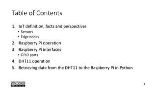
  • 27. Raspberry Pi Operating System • Raspbian is the official OS, based on the Debian Linux distribution • Also available: Ubuntu, Windows 10 IoT, OSMC, etc. • Choose and download from here www.raspberrypi.org/downloads • Unzip the file and make a block copy on a FAT32 SD card sudo dd bs=4m if=/home/user/2017-09-07-raspbian-stretch.img of=/dev/sd[x] (or /dev/mmcblk[x]) 27
  • 28. RPi Boot Process • No BIOS or battery backed memory by default • Uses specific, efficient but closed source bootloaders developed by Broadcom • Bootloaders and configuration files are located in the /boot directory of the RPi image 28
  • 29. Boot Diagnostics • Common cause for a Pi to fail to boot is a problem with the SD card • The Pi relies on files stored on the SD card for everything • If the Pi can’t talk to the card, it won’t display anything on the screen or show any signs of life at all • If the Pi’s PWR light glows when you connect the power supply but nothing else happens and the ACT (activity) light isn’t flickering to indicate data access, there is an SD card problem • Ensure that the card works when connected to a PC and that it shows the partitions and files expected of a well-flashed card • If the card works on a PC but not on the Pi, it may be a compatibility problem 29
  • 30. User Accounts • By default, Raspbian is configured with two user accounts • pi: normal user account (password raspberry) • root: superuser / administrator account with additional permissions • Raspbian by default is configured so that the root account can't be logged into using a password • Use sudo command instead 30
  • 31. RPi Configuration • The primary configuration file for the RPi is /boot/config.txt • Configure Raspbian with sudo raspi-config • Changes made using the raspi-config tool are reflected in this file • You can manually edit this file to enable/disable bus hardware, overclock the processors, etc. sudo nano /boot/config.txt • Another file /boot/cmdline.txt is for passing arguments (e.g., tty params, rootfs type, etc.) to the Linux kernel on boot sudo nano /boot/cmdline.txt 31
  • 32. Useful Raspbian Linux Commands • Start the GUI desktop startx • Update the system sudo apt-get update sudo apt-get upgrade sudo apt-get install <package-name> • Shutdown the system sudo shutdown –h now 32
  • 33. Configure the Wired Network • Check with ifconfig • Disable and re-enable network interface • sudo ifdown eth0 • sudo ifup eth0 • Configure a connection by editing /etc/dhcpcd.conf • Add lines interface eth0 static ip_address=192.168.0.13 static routers=192.168.0.254 static domain_name_servers=8.8.8.8 8.8.4.4 static domain_search=local • Restart the network stack sudo service networking restart 33
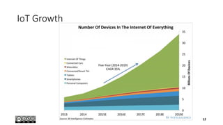
  • 34. Configure the Wireless Network • scan for nearby wireless access points sudo iwlist scan | less • Check network interface iwconfig wlan0 • Use wpasupplicant to connect the Pi to almost any wireless network (WPA, WPA2) • Edit the configuration file sudo nano /etc/wpa_supplicant/wpa_supplicant.conf • Add lines network={ [Tab] ssid="Your_SSID" [Tab] key_mgmt=WPA-PSK [Tab] psk="Your_WPA_Key" } • Restart interface ifup wlan0 34
  • 35. Connecting to the RPi using the Network • Show IP address ip addr • Connect using a CLI with SSH ssh [email protected] • Connect using a GUI with VNC sudo apt-get install tightvncserver • When the server starts, it will tell you which virtual desktop has been started. This will normally be session 1 New 'X' desktop is raspberrypi:1 • On the client, indicate the remote host as 192.168.0.111:1 35
  • 36. Zeroconf Networking • Avahi is a free zero-configuration networking (zeroconf) implementation, including a system for multicast DNS/DNS-SD service discovery • Avahi enables programs to publish and discover services and hosts running on a local network • A user can plug a computer into a network and have Avahi automatically advertise the network services running on the machine which could enable access to files and printers • On the RPi sudo apt-get install avahi-daemon • On the remote machine ssh [email protected] 36
  • 37. Bluetooth Connection • Switch your Bluetooth device on and activate pairing mode • Typically involves holding down a button or key, see device’s documentation • With the device in pairing mode, click the Bluetooth icon on the Raspbian taskbar (near the clock at the right edge of the screen) • Click on Add Device to launch the Add New Device menu • Find your chosen device in the list, and then click Pair • The Pi will launch the pairing procedure (differs from device to device), follow onscreen instructions to pair the two devices together 37
  • 39. Raspberry Pi GPIO Ports • GPIO stands for General Purpose Input Output • It is a term used to refer to ports that can be used either as inputs or outputs • The GPIO pins on the Raspberry Pi are connected directly to the GPIO ports on the processor • The processor runs at 3.3V and as such the GPIO ports are designed for 3.3V • The GPIO ports do not include any built-in protection!! • Giving an input that is above 3.3V, or drawing too much current from an output, can permanently damage the Raspberry Pi!! 39
  • 40. Raspberry Pi 3 Pinout 40
  • 41. +5V from the Raspberry Pi GPIO • The 5V connection on the GPIO connector is a fixed 5V power supply that can be used to power a low-power circuit from the Raspberry Pi • It is possible to connect an external 5V supply to that pin and use that to power the Raspberry Pi • The amount of current that can be taken from this supply is limited but it could be used to power low-power electronic circuits • Do not shorten accidentally one of those 5V pins 2 and 4 with any other GPIO pins or you will damage the SoC!! 41
  • 42. Default GPIO Pins • The GPIO port provides at least eight pins for general-purpose use by default: Pin 7, Pin 11, Pin 12, Pin 13, Pin 15, Pin 16, Pin 18, and Pin 22 • These pins can be toggled between three states: high, where they are providing a positive voltage of 3.3 V; low, where they are equal to ground or 0 V; and input • The two outputs equate to the 1 and 0 of binary logic and can be used to turn other components on or off • The GPIO port has pins dedicated to particular buses • Pi’s internal logic operates at 3.3 V, in contrast to many microcontroller devices (e.g., Arduino), which typically operate at 5 V!! • Devices designed for the Arduino may not work with the Pi unless a level translator or optical isolator is used between the two 42
  • 43. Universal Asynchronous Receiver/Transmitter (UART) Serial Bus • UART serial bus provides a simple two-wire serial interface • When a serial port is configured in the cmdline.txt file, this serial bus is used as the port for the messages • Connecting the Pi’s UART serial bus to a device capable of displaying the data reveals messages from the Linux kernel • The UART serial bus can be accessed on Pins 8 and 10, with Pin 8 carrying the transmit signal and Pin 10 carrying the receive signal (speed is set in cmdline.txt at 115,200 bps) 43
  • 44. Inter-Integrated Circuit (I2C) Bus • I2C bus is designed to provide communications between multiple integrated circuits (ICs) • In the Pi, this bus connects to the Broadcom BCM2835 SoC processor • These pins are connected to pull-up resistors located on the Pi, meaning no external resistors are required to access the I2C functionality • The I2C bus can be accessed on Pins 3 and 5, with Pin 3 providing the Serial Data Line (SDA) signal and Pin 5 providing the Serial Clock Line (SCL) signal • The I2C bus available on these pins is actually only one of two provided by the BCM2835 chip (bus 1 on RPi 3) • The second I2C bus is reserved for use by the Pi Camera Module and Touchscreen Display 44
  • 45. Serial Peripheral Interface (SPI) Bus • SPI is a synchronous serial bus that offers improved performance compared with I2C • SPI is a four-wire bus with multiple Chip Select lines, which allow it to communicate with more than one target device • The Pi’s SPI bus is available on Pins 19, 21, and 23, with a pair of Chip Select lines on Pin 24 and Pin 26 • Pin 19 provides the SPI Master Output, Slave Input (MOSI) signal • Pin 21 provides the SPI Master Input, Slave Output (MISO) signal • Pin 23 provides the Serial Clock (SLCK) used to synchronise communication • Pins 24 and 26 provide the Chip Select signals for up to two independent slave devices 45
  • 46. 1-Wire • The 1-Wire interface is another alternative to I2C and SPI, offering connectivity to and communication with sensors and other external hardware • Typically, 1-Wire is used to connect simple sensors—such as devices for reading the temperature or humidity of the environment—to the Raspberry Pi, and is rarely used by add-on boards 46
  • 47. Add-On Hardware • 100s of compatible add-on devices which connect through the multifunction GPIO header • Add-on boards for RPis are called Hardware Attached on Top (HAT) and should follow the HAT standard to ensure compatibility • The standard covers both the physical and electrical design of the add-on board • The board must attach to the 40-pin GPIO header and include mounting holes that line up with those on the Pi Model B+ and newer. It must also be rectangular, measuring 65 mm by 56 mm • EEPROM module on the board which contains information about how the board works, how the Pi’s GPIO pins are used, and a device tree for setting the board up within the operating system 47
  • 48. Sense HAT • Multifunction I/O board designed for use in the Astro Pi programme (orbiting the Earth as part of a science bundle sent up to the ISS) • Onboard sensors provide board’s orientation and position via a gyroscope, accelerometer, magnetometer, ambient air pressure, temperature, and humidity levels • Onboard 8x8 matrix of LEDs provides an output, and interaction is possible through the use of the Sense HAT’s five-way joystick 48
  • 49. Pi Camera Module v2 • Connect to the Camera Serial Interface (CSI) • Measures 25 mm on its longest edge and weighs 3 g • 8Mpx sensor, fixed-focus lens • Full HD video capture, 30 fps • NoIR version without IP filter (needs external IR LEDs) • H.264 hardware acceleration 49
  • 50. Using the Camera • Install the frame buffer image viewer sudo apt-get install fbi • View images using the tool fbi -a imagename.jpg • Still image capture with raspistill as JPEG (-e for other formats) • raspistill -o testcapture.jpg • Video capture (size in px, duration in ms) with raspivid as H.264 raspivid –t 60000 -w 1280 -h 720 -o hdvideo.h264 50
  • 51. Digital Humidity & Temperature Sensor/Module Part 4
  • 52. DHT11 Temperature and Humidity Sensor • Measure humidity and temperature of the surrounding environment • Humidity measurement range : 20% ~95% • Humidity measurement error : ±5% • Temperature measurement range : 0℃~50℃ • Temperature measurement error : ±2 ℃ • Operating voltage : 3.3 V~5 V • Digital output form • PCB Dimension: 32 mm x 14 mm 52
  • 53. DHT11 Sensor Pinout • Left-to-right • Pin 1: VCC • Pin 2: DATA • Pin 3: null • Pin 4: GND 53
  • 54. Power and Interconnection • DHT11’s power supply is 3 to 5.5V DC • When power is supplied to the sensor, do not send any instruction to the sensor in within 1 second in order to pass the unstable status • MCU = µcontroller unit 54
  • 55. DHT11 Module Pinout • Sensor soldered on PCB • Left-to-right • Pin 1: VCC (V) • Pin 2: DATA (S) • Pin 3: GND (G) 55
  • 56. Jumper Wires • Dupont Cable • 10cm length • 2.54mm pin width • 1 pin female to female for arduino/raspberry pi 56
  • 57. Communication Process • Serial Interface (Single-Wire Two-Way) • Single-bus data format is used for communication and synchronization between MCU and DHT11 sensor • One communication process is about 4ms • Data consists of decimal and integral parts • A complete data transmission is 40bit, and the sensor sends higher data bit first • The sensor can be queried once per second maxi 57
  • 58. Data Format and Checksum • The data is transmitted in this format: 8bit integral RH data + 8bit decimal RH data + 8bit integral T data + 8bit decimal T data + 8bit check sum • If the data transmission is correct, the check sum should be equal to the lower 8bit of the result of (8bit integral RH data + 8bit decimal RH data + 8bit integral T data + 8bit decimal T data) 58
  • 59. Overall Communication Process • When MCU (black) sends a start signal, DHT11 (green) changes from the low-power-consumption mode to the running-mode, waiting for MCU completing the start signal • Once it is completed, DHT11 sends a response signal of 40-bit data to MCU • Without the start signal from MCU, DHT11 will not reply • Once data is collected, DHT11 will change to the low-power-consumption mode until it receives a start signal from MCU again 59
  • 60. MCU Sends out Start Signal to DHT • The default status of the DATA pin is high-voltage level • When the communication between MCU (black) and DHT11 (green) starts, MCU will pull down the DATA pin for 18ms, this is called Start Signal, to ensure DHT11 has detected the signal • Then MCU will pull up DATA pin for 20-40µs to wait for DHT11’s response 60
  • 61. DHT Response Signal to MCU • Once the DHT detects the start signal, it will send out a low-voltage level response signal, which lasts 80µs • Then the DHT sets the voltage level from low to high and keeps it for 80µs, and prepares for data transmission 61
  • 62. Data « 0 » Indication • When DHT is sending data to MCU, every bit of data begins with the 50µs low-voltage-level and the length of the following high-voltage- level signal determines whether data bit is "0" or "1“ • Data bit “0” has 26-28µs high-voltage length 62
  • 63. Data « 1 » Indication • Data bit “1” has 70µs high-voltage length • When the last bit data is transmitted, DHT11 pulls down the voltage level and keeps it for 50µs • Then the voltage will be pulled up by the resistor to set it back to the free status • If the response signal from DHT is always at high-voltage-level, the DHT is not responding properly, check the connection 63
  • 64. Retrieving Data from the DHT11 to the Raspberry Pi Part 5
  • 65. The Design Process in a Nutshell • Designing a circuit is a multi-step process 1. Start with the idea 2. Research the available components, 3. Design it into a circuit showing how components will be connected 4. Prototype the circuit by making a temporary circuit before creating the final finished one • The final circuit could be built on an off-the-shelf board such as stripboard or made into a complete printed circuit board, depending on your budget and the complexity of the circuit 65
  • 66. An Iterative Process • Each of these stages can be repeated as necessary until you come to the final design • As you move through the stages, the potential cost increases both in terms of money and the time • The earlier you identify any potential problems the less it will cost • Don’t be afraid to go back to the start rather than trying to continue with a design that isn’t working 66
  • 67. Electronic Equipment • An electronic breadboard provides a grid of holes spaced at 2.54 mm intervals into which components can be inserted and removed • Below each grid is a series of electrical contacts which allow components in the same row to be connected together without wires • Jumper wires are used to connect one row to another, or to connect the breadboard to the Pi’s GPIO port (use solid-core wire rather than stranded-core wire) • Stripboard is a single-use breadboard where components need to be soldered into place making a permanent electronic circuit 67
  • 68. Resistors • A resistor is a passive two- terminal electrical component that implements electrical resistance as a circuit element • Resistors are measured in ohms, written as the symbol Ω • Resistance value in ohms is calculated from the color bands that adorn the resistor’s surface 68
  • 69. Raspberry Pi 2/3 40-pin I/Os • Hardware interfaces for the Raspberry Pi 3 are exposed through the 40-pin header J8 on the board • 24x - GPIO pins • 1x - Serial UARTs (RPi3 only includes mini UART) + 2x - SPI bus + 1x - I2C bus • 2x - 5V power pins + 2x - 3.3V power pins + 8x - Ground pins 69
  • 70. Connections with GPIOs on RPi3 Raspberry Pi DHT11 Module 3.3v P1 P1 VCC (V) GND P6 P3 GND (G) GPIO4 (GPCLK0) P7 P2 DATA (S) 70
  • 71. RPi.GPIO Python Library • This package provides a python class to control the GPIO pins on a RPi • This module is unsuitable for real-time or timing critical applications • It can not be predicted when Python will be busy garbage collecting • It also runs under the Linux kernel which is not suitable for real time applications as it is multitasking O/S and another process may be given priority over the CPU, causing jitter in your program • For true real-time performance and predictability, use a µcontroller (e.g., Arduino) https://pypi.python.org/pypi/RPi.GPIO • The package’s documentation is here https://sourceforge.net/p/raspberry-gpio-python/wiki/Examples/ 71
  • 72. RPIO Python Library • RPIO.py extends RPi.GPIO and uses the BCM GPIO numbering scheme by default • https://pythonhosted.org/RPIO/ • GPIO interrupts with debouncing • Interrupts are used to receive notifications from the kernel when GPIO state changes occur • If debounce_timeout_ms is set, interrupt callbacks will not be started until the specified milliseconds have passed since the last interrupt • Minimized cpu consumption, fast notification times, ability to trigger on specific edge transitions (rising, falling or both) • TCP socket interrupts • GPIO input & output • Hardware PWM 72
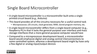
  • 73. Initialisation and Data Collecting Code import RPi.GPIO as GPIO import time def bin2dec(string_num): return str(int(string_num, 2)) data = [] # BCM numbering system GPIO.setmode(GPIO.BCM) GPIO.setup(4,GPIO.OUT) GPIO.output(4,GPIO.HIGH) time.sleep(0.025) #25ms # 20ms start signal GPIO.output(4,GPIO.LOW) time.sleep(0.02) # set input pin to high level GPIO.setup(4, GPIO.IN, pull_up_down=GPIO.PUD_UP) # polling DHT 500x for i in range(0,500): # read binary data from DHT data.append(GPIO.input(4)) # variables initialisation count = 0 bit_count = 0 HumidityBits = "" TemperatureBits = "" crc = "" 73
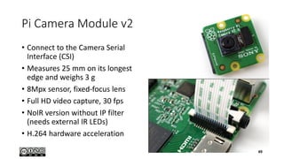
  • 74. Reading the Values from the Data try: ..# skip all first 1’s (DHT response) while data[count] == 1: ....count = count + 1 # read first 32 bits for i in range(0, 32): bit_count = 0 # skip 0’s while data[count] == 0: ......count = count + 1 ....# read 1’s while data[count] == 1: ......bit_count = bit_count + 1 count = count + 1 if bit_count>3: #if 1’s length is>3(70µs) if i>=0 and i<8: #read integral H part ........HumidityBits = HumidityBits + "1" if i>=16 and i<24: #read integral T part TemperatureBits = TemperatureBits + "1" else: #if 1’s length is<4(27µs) if i>=0 and i<8: HumidityBits = HumidityBits + "0" if i>=16 and i<24: TemperatureBits = TemperatureBits + "0“ except: print "ERR_DATA_READ" exit(0) 74
  • 75. Checking CRC and Printing Results # read last 8 bits for the CRC try: ..for i in range(0, 8): ....bit_count = 0 while data[count] == 0: ......count = count + 1 while data[count] == 1: bit_count = bit_count + 1 count = count + 1 if bit_count > 3: crc = crc + "1" else: crc = crc + "0" except: print "ERR_CRC_READ" exit(0) # convert binary strings to decimal Humidity = bin2dec(HumidityBits) Temperature = bin2dec(TemperatureBits) # check CRC and print if (int(Humidity) + int(Temperature) – int(bin2dec(crc)) == 0): print "Humidity:"+ Humidity +"%" print "Temperature:"+ Temperature +"C" else: print "ERR_CRC_CALC" exit(0) 75
  • 76. Comments • Reading 500 samples is arbitrary • Reading up to three 1’s for defining a 0 and more for defining a 1 is arbitrary • Your mileage may vary -> see post on the right • Print the data[ ] array to see the signals • Should we skip the first 0’s? • The CRC computation is wrong • Why? Correct it • Use interruptions instead of polling • “I discovered the following: • - a "0" data/crc bit is a row of 7-8 consecutive '1' samples • - a "1" data/crc bit is a row of 21-22 consecutive '1' samples • I changed the trigger to 13 consecutive samples : below, it's a 0 and above, it's a 1 • Obviously, I need far more samples (avg 1050-1150) so I take 1300, just to make sure” 76
  • 77. References • Original source code • Provides also (much better) C code (with correct checksum  ) http://www.uugear.com/portfolio/dht11-humidity- temperature-sensor-module/ • Advanced code for the DHT22 • Uses another library (pigpio) with callbacks https://www.raspberrypi.org/forums/viewtopic.php?p=51557 5#p515575 77
  • 78. Using AdaFruit API import Adafruit_DHT sensor = 11 pin = 27 while True: humidity, temperature = Adafruit_DHT.read_retry(sensor, pin) # GPIO27 (BCM notation) print("Humidity={}%; Temperature={}C".format(humidity, temperature)) • Adafruit tutorial https://learn.adafruit.com/dht-humidity-sensing-on-raspberry-pi-with-gdocs- logging/wiring • Daskal Tutorial http://invent.module143.com/daskal_tutorial/raspberry-pi-3-gpio-dht11- digital-temperature-humidity-sensor/ 78
  • 79. WiringPi C Library • WiringPi is a PIN based GPIO access library written in C for the BCM2835 used in the Raspberry Pi • Released under the GNU LGPLv3 license • Usable from C, C++ and RTB (BASIC), the documentation is here http://wiringpi.com/ • The C library is here https://git.drogon.net/ • Python wrappers are here https://github.com/WiringPi/WiringPi-Python 79
  • 80. Running a Program as a Service • On Raspbian, the startup and running processes are controlled using systemd • To register the program as a service, you need a special service file stored in the /etc/systemd/system/ directory; it must end with the suffix .service and needs to be created as the root user using sudo sudo vi /etc/systemd/system/dht11.service • To start the service sudo systemctl start dht11 • To stop the service sudo systemctl stop dht11 80
  • 81. Service File Content [Unit] Description=DHT11 control program [Service] Type=simple ExecStart=/usr/bin/python3 /home/pi/dht11/dht11.py User=pi [Install] WantedBy=default.target 81