SlideShare a Scribd company logo
Kubernetes Networking
Networking Models
IBM Client Developer / © 2020 IBM Corporation 2
TCP/IP Model (Internet Protocol Suit)
• Link Layer, corresponds to L2 in OSI model.
• Internet Layer (IP), networking interface or internetworking, addressing and routing for TCP/IP
• Transport Layer (UDP/TCP)
• Application Layer (HTTP, FTP, etc) corresponds to L5/L6/L7 in OSI model.
Open Systems Interconnection (OSI) Model
• L1 – Physical
• L2 – Data Link (Ethernet, PPP, VLAN, etc)
• L3 – Network (NAT, IP, IPSEC etc)
• L4 – Protocol Suites (NetBIOS, SCTP, TCP, UDP, etc)
• L5 – Session (RPC, SDP, SMB, SOCKS, etc)
• L6 – Presentation (TLS, SSL, FTP, IMAP, SSH, etc)
• L7 – Application (SOAP, DHCP, DNS, HTTP, HTTPS, NFS, POP3, SMTP, FTP, IRC, SSH, etc)
OSI Model for Kubernetes
IBM Client Developer / © 2020 IBM Corporation 3
source: https://coreos.com/blog/cluster-osi-model.html
L1: bare metal, VMs, cloud (CPU, RAM, disk, network)
L2: OS, Machine Application Binary Interface (ABI) (system calls, device
drivers, etc), kernel + [system, cgroups/namespaces, jails, zones) (RHEL,
CoreOS)
L3Cluster Consensus (etcd (consensus db built with Raft consensus
algorithm), Apache ZooKeeper, consul)
Etcd uses Raft, a consensus algorithm for distributing configuration, state and metadata information within a cluster and monitoring for any changes
to the data stack
L4: Cluster Resources (CNI, CSI)
L5: Container Orchestration (CO) (Kubernetes, OpenShift, CloudFoundry)
L6: Containers (Rocket, Docker, Podman, CRIO, containerd)
Etcd: The etcd project’s focus is safely storing critical data of a distributed system and it demonstrated its quality early on. etcd was created by the
CoreOS team in 2013, inspired by Chubby, a key-value store created for Google’s internal cluster infrastructure. Etcd was contributed to the CNCF
by Red Hat and CoreOS in December 2018. source: https://coreos.com/blog/history-etcd
Software Defined Networking (SDN)
IBM Client Developer / © 2020 IBM Corporation 4
Software Defined Networking (SDN) uses software-based controllers or APIs to create and control a virtual network or traditional hardware.
Network virtualization segments different virtual networks within a single physical network or connect devices on different physical networks to create a
single virtual network.
SDN is a software defined way to control the traffic or routing of data packets through a server.
• Using an open standard software-based controller, using a single protocol to communicate with different hardware devices.
• Configure network services and allocate virtual resources to change network infrastructure in real time, to optimize data flow.
• Visibility into the entire network and creation of separate zones for devices with different security levels.
Parts of SDN architecture:
• Applications,
• Controllers,
• Networking devices.
Network Functions Virtualization (NFV) abstracts network functions from hardware and supports SDN by providing the infrastructure on which SDN
software runs.
Network Service Chaining, also known as Service Function Chaining (SFC) uses SDN to create a chain of connected network services, such as L4-7
services like firewalls, network address translation (NAT), and intrusion protection.
Network Functions Virtualization (NFV)
IBM Client Developer / © 2020 IBM Corporation 5
Network Functions Virtualization (NFV) is a way to virtualize network services such as routers, firewalls, and load balancers.
The NFV architecture is proposed by the European Telecommunications Standards Institute (ETSI), NFV consists of
• Virtualized Network Functions (VNF),
• Network Functions Virtualization infrastructure (NFVi), such as Hypervisors, and
• Management, Automation and Network Orchestration (MANO).
Container Networking
IBM Client Developer / © 2020 IBM Corporation 6
Container Networking is based for a large part on Linux networking. Containers use Linux partitioning features as Cgroups and
Namespaces that allow container processes to map to network, storage and other namespaces. Container networking uses
network namespaces of the Linux kernel.
Network namespaces:
• A container isolated network uses its own virtual interfaces like routing tables, L2 isolation, sockets and IPTABLE rules.
• Containers use iproute2 to interact with network namespaces.
• Network namespaces are stored in /var/run/netns
• Two types of network namespaces:
– Root namespace (ip link)
– Non-root namespace (ip netns, ip link)
A container network interface belongs to only one network namespace. Multiple containers require multiple interfaces or using
pseudo-interfaces like:
• Virtual bridge, using Virtual Ethernet device (veth) pairs as a tunnel between container and root namespace, and a Linux
bridge or OpenvSwitch (OVS) for connectivity between containers and external (real) interfaces.
• Multiplexing, using a network device with multiple virtual interfaces and packet forwarding rules (MACVLAN, IPVLAN),
• Hardware networks like SR-IOV (supported by most Network Interface Controllers (NIC)).
Container Networking
IBM Client Developer / © 2020 IBM Corporation 7
Docker networking uses pluggable drivers. Several drivers exist by default and provide core networking functionality.
Bridge networks
Default Docker networking mode, a Link Layer device which forwards traffic between network segments, using a software bridge, which
allows containers on the same bridge network on the same host to communicate. The Docker bridge driver automatically installs rules in
the host machines.
Docker0: a Linux bridge created by docker daemon
• 1 interface to host namespace
• All containers on the host are attached to docker0 via veth-pair
• Container gets private IP address assignment, with random MAC generation to avoid MAC collissions and ARP problems.
docker run –d –P –net=bridge training/webapp python app.py
docker ps
docker exec <containerid> ip a
Host networks
Use host’s network and share the host’s networking namespace. Container does not get its own IP-address.
Basic port mapping on host network to reach services
ifconfig | grep –A 2 eth0
docker run –d –net=host training/webapp python app.py
docker ps
docker exec <containerid> ip a | grep –A 2 eth0
Container Networking
IBM Client Developer / © 2020 IBM Corporation 8
Overlay
Creates a distributed network across multiple hosts to connect multiple containers. When you initialize a container host, two
new networks are created:
• An overlay network called ingress
• A bridge network called docker_gwbridge
All pods on the host are attached to docker0 via veth-pair
Macvlan
Connect directly to physical network, assigning a MAC address to a container’s virtual network interface, making it appear as a
physical device on the network. You can also use ipvlan, which uses L3 and L2 mode, and use an L2 bridge.
No Networking
Disable all networking, usually in conjunction with a custom network driver.
Container Network Interface (CNI)
IBM Client Developer / © 2020 IBM Corporation 9
CNI is a vendor-neutral interface between container runtimes and networks, independent of the Container Orchestration (CO) platform, e.g. Kubernetes,
OpenShift, Docker, rkt, Mesos, CloudFoundry, podman, CRI-O, Kurma, Amazon ECS. CNI (Container Network Interface) originates at CoreOS as part of
rkt. Now a CNCF project.
CNI is responsible for network connectivity of containers and removing allocated resources when the container is deleted. It consists of a specification
and libraries for writing plugins to configure network interfaces. CNI defines a basic execution flow and JSON-based configuration format for network
operations. Plugins are executables in the host, and Kubelet is the runtime on the node.
The container runtime creates the Network Namespace, identifies the network to attach containers, and invokes the plugin.
The CNI plugin or bridge program implements:
1. Create veth Pairs
2. Create Bridge Network/Interface
3. Attach vEth to Namespace
4. Attach other vEth to Bridge
5. Assign IP address
6. Bring up interfaces
7. Enable NAT
Basic plugin commands:
• ADD
• DEL
• CHECK
• VERSION
E.g. the container runtime invokes `bridge add <cid> <namespace>` to add a container to a network.
Container Network Interface (CNI)
IBM Client Developer / © 2020 IBM Corporation 10
Container Networking is based for a large part on Linux networking.
Multi-networking
CNI supports multi-networking, but Kubernetes by default does not: a Kubernetes pod is exposed only to 1 interface (and
loopback). Multus by Intel supports multi-networking using CRD-based network objects.
Reference plugins: bridge, loopback, vlan, macvlan, ipvlan, host-device, ptp (point-to-point), Windows bridge, Windows
overlay.
IPAM (IP Address Management): host-local, DHCP, static
Meta (chained) plugins: bandwidth, firewall, flannel, portmap, source-based routing, tuning
3rd
Party plugins: Calico, Weave, Cilium, Multus, Romana, SR-IOV (Single Root I/O Virtualization), Nuage, Amazon ECS, Linen,
Silk (CF)
* IBM Cloud Kubernetes implements Calico
* OpenShift supports using SR-IOV hardware on nodes
Container Network Model (CNM)
IBM Client Developer / © 2020 IBM Corporation 11
Aka Libnetwork supported by Docker
https://github.com/docker/libnetwork
Kubernetes Architecture
IBM Client Developer / © 2020 IBM Corporation 12
• At its core, Kubernetes is a database (etcd) with "watchers" and "controllers" that react to changes in etcd, etcd is a consensus database using Raft
• The kube-api-server is an API server that exposes the Kubernetes API, all traffic goes through the API Server
• The kube-scheduler watches for new Pods not assigned to a node and selects a node to run the Pod on,
• The kube-controller-manager runs the controller loops that make Kubernetes,
• The cloud-controller-manager interacts with the underlying cloud provider,
• The etcd key-value store represents the user defined desired state of the objects,
• The kubelet makes sure that containers are running in a Pod,
• The kube-proxy is a network proxy that maintains network rules on nodes,
API Server
IBM Client Developer / © 2020 IBM Corporation 13
The control plane on the master node(s) consists of the API
Server, the Controller Manager and Schedulers. The API Server
is the only component that talks directly to etcd and is a
gateway to etcd, which is the consensus database for the state
of your application cluster.
The API Server:
• Serves the Kubernetes API,
• Proxies cluster components such as the Kubernetes UI,
• Allows manipulation of the state of objects,
• Persists the state of objects in etcd.
https://www.openshift.com/blog/kubernetes-deep-dive-api-server-part-1
API Server
IBM Client Developer / © 2020 IBM Corporation 14
Workflow:
1. Transport security: API Server is accessed via port 443 protected by TLS and it presents a certificate.
2. Authentication: running 1 or more authentication modules (client certificates, password, plain tokens, bootstrap tokens,
JSON web tokens)
3. Authorization: request must include username, action and target object, and is verified against a policy. Multiple
authorization modules are supported: ABAC, RBAC, Webhook.
4. Admission Controller: modify or reject requests, does not effect reads.
source: https://kubernetes.io/docs/concepts/security/controlling-access/
Request Flow
IBM Client Developer / © 2020 IBM Corporation 15
The API Server handles requests from within and to outside the
cluster. When an HTTP request hits the Kubernetes API:
• HTTP request is processed by a chain of Filters registered
in DefaultBuildHandlerChain(). Either the filter passes and
attaches respective info to ctx.RequestInfo, such as
authenticated user or returns an appropriate HTTP response
code.
• Next, the Multiplexer or MUX routes the HTTP request to
the respective handler, depending on the HTTP path.
• The Routes (as defined in routes/*) connect handlers with
HTTP paths.
• The handler takes the HTTP Request and Context (like user,
rights, etc.) and delivers the requested object from storage.
https://www.openshift.com/blog/kubernetes-deep-dive-api-server-part-1
Admission Controller
IBM Client Developer / © 2020 IBM Corporation 16
An admission controller is a piece of code that intercepts requests to the Kubernetes API server prior to persistence of the object, but after the request
is authenticated and authorized. The admission control process has two phases: a mutating phase and validating phase. The controllers are compiled
into the kube-apiserver binary.
Examples of default admission controllers: AlwaysAdmit, AlwaysPullImages, AlwaysDeny, CertificateApproval, CertificateSigning, DefaultStorageClass,
EventRateLimit, NameSpaceLifecycle, NodeRestriction, PodNodeSelector, PersistentVolumeClaimResize, PodSecurityPolicy, ResourceQuota,
ServiceAccount among more than 30, and 2 webhooks with a special role: MutatingAdmissionWebhook and ValidatingAdmissionWebhook.
The webhooks do not implement any policy logic themselves, but is obtained from a REST endpoint. This approach decouples the admission controller
logic from the Kubernetes API server, allowing custom logic to be executed whenever resources are created, updated, or deleted in a Kubernetes
cluster. The webhook handles an AdmissionReview request sent by the API Server and sends back a decision in the same AdmissionReview it received.
OpenShift Container Platform (OCP) has a default set of admission plug-ins enabled for each resource type.
Kubernetes Networking
IBM Client Developer / © 2020 IBM Corporation 17
• All pods can communicate with all pods without NAT
• All nodes can communicate with all pods without NAT
• The IP of the pod is the same for itself as it is for others
4 networking problems remain:
• Container to container
• Pod to pod
• Pod to service
• Internet to service
VM
Typically, network communication on a VM interacts with an Ethernet device. In Linux,
that network communication runs within a network namespace with its own logical
networking stack with its own routes, firewall rules, and network devices.
Container to container
A pod is a group of containers that share a network namespace, they all have the same IP
address and port space assigned and can find each other via localhost. Containers join
the network namespace with the --net=container: function. Containers within a pod also
can access shared volumes, which are part of the pod and available to be mounted into
the applications filesystem. A pod exists in its own Ethernet namespace.
VM
root network
namespace
eth0
VM
root network
namespace
eth0
Pod 1 ns Pod 2 ns
ctr1 ctr2 ctr1 ctr2
Kubernetes Networking
IBM Client Developer / © 2020 IBM Corporation 18
Pod to pod
A pod exists in its own Ethernet namespace that needs to communicate with other network namespaces
on the same node. Pods or Namespaces can be connected using a Linux Virtual Ethernet Device or veth
pair, consisting of two virtual interfaces across multiple namespaces. One side of the veth pair is
connected to the root network namespace, and the other side to the Pod’s network namespace. This setup
can be replicated for all pods on the VM. The veth connects a pod namespace to the root namespace.
A bridge connects pod namespaces. A Linux Ethernet bridge is a virtual Layer 2 (L2) networking device to
connect two networks by maintaining a forwarding table between sources and destinations by examining
the destination of the data packets and looking at the MAC-address of each Ethernet device in the network.
Bridges implement the ARP protocol to discover the link-layer MAC address associated with an IP address.
The bridge broadcasts the data frame out to connected devices except the sender and the device that
responds to the frame is stored in a lookup table. But the Kubernetes networking model dictates that pods
can reach pods by their IP address across nodes.
Generally, every Node in your cluster is assigned a CIDR block specifying the IP addresses available to
Pods running on that Node. Once traffic destined for the CIDR block reaches the Node it is the Node’s
responsibility to forward traffic to the correct Pod. On failure to find the correct MAC address, the bridge
sends the packet out the default route — the root namespace’s eth0 device. At this point the route leaves
the Node and enters the network. The network routes the packet to the correct Node based on the CIDR
block assigned to the Node. How this is done is network specific.
The Container Networking Interface (CNI) provides a common API for connecting containers to the
outside network.
VM
root netns
eth0
Pod 1 ns Pod 2 ns
veth0 veth1
eth0 eth0
VM
eth0
Pod 1 ns Pod 2 ns
veth0 veth1
eth0 eth0
root netns
cbr0
Service
IBM Client Developer / © 2020 IBM Corporation 19
The connection for Pod to service and Internet to service is handled by Kubernetes Service types.
The Service object is an abstraction of a logical set of Pods exposed through Endpoints that are updated whenever the set of
Pods in a Service change. Every Service defined in the cluster is assigned a DNS name that maps to the ClusterIP of the
Service. Kubelets on nodes in the cluster are configured to use the IP of the DNS Service to resolve DNS names for Service
Discovery. The Endpoints for a set of pods are determined using a Selector. Labels are key/value pairs that are attached to
objects can be used to organize and select subsets of objects. The label selector is the core grouping primitive in Kubernetes.
Service types:
• ClusterIP, default Service type that exposes the service on a cluster-internal IP only.
• NodePort, exposes the service on each Node’s IP at a static port (the NodePort). A ClusterIP service, to which the NodePort
service will route, is automatically created.
• LoadBalancer, on top of a NodePort and ClusterIP, exposes the service externally using a cloud provider’s load balancer.
• ExternalName, maps the service to the externalName field (e.g. foo.bar.example.com) by returning a CNAME record with its
value.
• Ingress
• Route
Ingress
IBM Client Developer / © 2020 IBM Corporation 20
An Ingress resource manages external access to the services in a cluster, typically HTTP/HTTPS. Ingress can also provide load balancing,
TLS termination and name-based virtual hosting. Ingress consists of an Ingress API object and the Ingress Controller. The Ingress
Controller implements the Ingress API. The Ingress Controller is usually a load balancer for routing external traffic to your Kubernetes
cluster and is responsible for L4-L7 Network Services.
Ingress consists of three components:
• Ingress resources,
• L7 Application Load Balancer (ALB),
• An external L4 load balancer to handle incoming requests across zones, depending on the provider.
To expose an app by using Ingress, you must create a Kubernetes service for your app and register this service with Ingress by defining an
Ingress resource. The Ingress resource is a Kubernetes resource that defines the rules for how to route incoming requests for apps.
source: https://cloud.ibm.com/docs/containers?topic=containers-ingress-about
apiVersion: networking.k8s.io/v1beta1
kind: Ingress
spec:
backend:
serviceName: helloworld
servicePort: 8080
Service
IBM Client Developer / © 2020 IBM Corporation 21
Ingress Application Load Balancer (ALB)
IBM Client Developer / © 2020 IBM Corporation 22
The Ingress Application Load Balancer (ALB) is a layer 7 (L7) load balancer which implements the NGINX Ingress controller. A layer 4 (L4)
LoadBalancer service exposes the ALB so that the ALB can receive external requests that come into your cluster.
The Application Load Balancer (ALB) is an external load balancer that listens for incoming HTTP, HTTPS, or TCP service requests. The ALB
then forwards requests to the appropriate app according to the rules defined in the Ingress resource.
When you create a standard cluster, IBM Cloud Kubernetes Service automatically creates a highly available ALB in each zone where you
have worker nodes. In classic clusters, the Ingress subdomain for your cluster is linked to the public ALB IP addresses. For classic clusters,
the ALB is a Multi-Zone Load Balancer (MZLB) that IBM Cloud Kubernetes Service creates for you.
In a VPC cluster, one public VPC load balancer is automatically created outside of your cluster in your VPC. The public VPC load balancer
puts the public IP addresses of your public ALBs behind one hostname. In VPC clusters, a hostname is assigned to the ALBs because the
ALB IP addresses are not static. This ALB hostname is different than the Ingress subdomain. The services that expose your ALBs on public
or private IP addresses are formatted as public-abc12 in the kube-system namespace.
The Kubernetes Ingress image is built on the community Kubernetes project's implementation of the NGINX Ingress controller. The
Kubernetes Ingress controller image is now supported for Ingress ALBs, and all new ALBs run the Kubernetes Ingress image by default.
source: https://cloud.ibm.com/docs/containers?topic=containers-ingress-about
Ingress Application Load Balancer (ALB)
IBM Client Developer / © 2020 IBM Corporation 23
ibmcloud ks ingress secret create --cluster <cluster_name> --cert-crn <CRN> --name <secret_name> --
namespace <namespace>
apiVersion: networking.k8s.io/v1beta1 # For Kubernetes version 1.19, use networking.k8s.io/v1 instead
kind: Ingress
metadata:
name: community-ingress-resource
annotations:
kubernetes.io/ingress.class: "<public|private>-iks-k8s-nginx"
spec:
tls:
- hosts:
- <domain>
secretName: <tls_secret_name>
rules:
- host: <domain>
http:
paths:
- path: /<app1_path>
backend:
serviceName: <app1_service>
servicePort: 80
- path: /<app2_path>
backend:
serviceName: <app2_service>
servicePort: 80
kubectl apply -f ingress-resource.yaml -n <namespace>
Route
IBM Client Developer / © 2020 IBM Corporation 24
The Route is an OpenShift resource that was created before
the Ingress was added to Kubernetes. Route also enables
external access to services with additional capabilities like
splitting traffic between multiple backends, sticky sessions.
Route principles heavily influenced the Ingress design.
When a Route object is created on OpenShift the built-in
HAProxy load balancer exposes the requested service and
makes it externally available.
Routes are assigned a hostname from the router subdomain
that external clients can use to send requests to your app.
OpenShift offers 4 types of routes:
• Simple, to handle non-encrypted HTTP traffic,
• Passthrough, to pass TLS connections without
interruption to the pod, no TLS termination,
• Edge, to handle encrypted HTTPS traffic for non-
encrypted HTTP endpoints,
• Re-encrypt, uses TLS termination and new TLS
connection between router and pod.
source: https://cloud.ibm.com/docs/openshift?topic=openshift-openshift_routes
DNS Server
IBM Client Developer / © 2020 IBM Corporation 25
The Kubernetes DNS server watches the Kubernetes API for new Services and changes. It creates a set of DNS records for
each service. Kubernetes DNS schedules a DNS Pod and Service on the cluster, and configures the kubelets to tell individual
containers to use the DNS Service's IP to resolve DNS names. Pods can resolve Services by their DNS name.
In Kubernetes version 1.11 and later, CoreDNS is recommended and installed by default with kubeadm. CoreDNS is a DNS
server written in Go. There are currently about 30 plugins included in the default CoreDNS install, as well as external plugins.
When a query is processed by CoreDNS, the following steps are performed with the request:
- Route request to the closest zone and port,
- Route request through the static plugin chain,
- Each plugin inspects the request and determines if it should process the request, processing means responding to client.
Kubernetes also supports DNS SRV (DNS Service) records for named ports. If the `my-service.my-ns` Service has a port named
"http" with the protocol set to TCP, you can do a DNS SRV query for `_http._tcp.my-service.my-ns` to discover the port number
for `http` as well as the IP address.
The Kubernetes DNS server is the only way to access ExternalName Services.
DNS policies can be set per pod via the `dnsPolicy` field: Default (inherit from node), ClusterFirst (default, forward to
upstream nameserver), ClusterFirstWithHostNet, None. The `dnsConfig` field on a Pod, allows you control on DNS settings for
a Pod: nameservers, searches, options.
Network Policy
IBM Client Developer / © 2020 IBM Corporation 26
By default, pods are non-isolated and accept traffic from any source. Network isolation and traffic control at the IP address or
port level, OSI layer 3 or 4 (L3 or L4), in a cluster is implemented by using a Container Network Interface (CNI) plug-in that
supports Kubernetes network policy. A NetworkPolicy is a set of rules applied to a collection of endpoints that match a label
selector within a namespace. For non-namespaced network policies, use a GlobalNetworkPolicy.
There are four kinds of selectors in an ingress from section or egress to section:
• podSelector,
• namespaceSelector,
• podSelector and namespaceSelector,
• ipBlock for IP CIDR ranges.
Every IBM Cloud Kubernetes Service cluster is set up with a network plug-in called Calico. When a Kubernetes network policy
is applied, it is automatically converted into a Calico network policy.
Network Policy
IBM Client Developer / © 2020 IBM Corporation 27
apiVersion: networking.k8s.io/v1
kind: NetworkPolicy
metadata:
name: helloworld-deny-all
spec:
podSelector: {}
policyTypes:
- Ingress
- Egress
apiVersion: networking.k8s.io/v1
kind: NetworkPolicy
metadata:
name: allow-helloworld
spec:
policyTypes:
- Ingress
podSelector:
matchLabels:
app: helloworld
ingress:
- {}
Security Context
IBM Client Developer / © 2020 IBM Corporation 28
A security context defines privilege and access control settings for a Pod or Container. Security context settings include, but
are not limited to:
• Discretionary Access Control (DAC),
• Security Enhanced Linux (SELinux),
• Linux Capabilities,
• Seccomp,
• SecurityContextConstraint (SCC), ServiceAccount (SA), and Role Based Access Control (RBAC),
Pod Security Policy
IBM Client Developer / © 2020 IBM Corporation 29
Pod Security Policies enable fine-grained authorization of pod creation and updates. A Pod Security Policy is a cluster-level
resource that controls security of the pod specification. The PodSecurityPolicy object defines a set of conditions that a pod
must run. PodSecurityPolicies are implemented as an admission controller.
Group Name / DOC ID / Month XX, 2018 / © 2018 IBM Corporation 30

More Related Content

Similar to KubernetesNetworkingAndImplementation-Lecture.pdf (20)

PDF
Simplify Networking for Containers
LinuxCon ContainerCon CloudOpen China
 
PDF
An Introduce of OPNFV (Open Platform for NFV)
Mario Cho
 
PPTX
Openstack Quantum yahoo meetup 1 23-13
Dan Wendlandt
 
PDF
Openstack Workshop (Networking/Storage)
Affan Syed
 
PPTX
OpenStack Networking and Automation
Adam Johnson
 
PDF
IBM Bluemix Nice meetup #5 - 20170504 - Orchestrer Docker avec Kubernetes
IBM France Lab
 
PPTX
Secure Your Containers: What Network Admins Should Know When Moving Into Prod...
Cynthia Thomas
 
PDF
End-to-end IoT solutions with Java and Eclipse IoT
Benjamin Cabé
 
PPTX
Microservices and containers networking: Contiv, an industry leading open sou...
Codemotion
 
PPTX
Edge Computing: A Unified Infrastructure for all the Different Pieces
Cloudify Community
 
PPTX
Comparison of existing cni plugins for kubernetes
Adam Hamsik
 
PPTX
Open stackaustinmeetupsept21
Brent Doncaster
 
PDF
4. CNCF kubernetes Comparison of-existing-cni-plugins-for-kubernetes
Juraj Hantak
 
PDF
State of the OpenDaylight Union
Open Networking Summit
 
PDF
Developers’ mDay u Banjoj Luci - Janko Isidorović, Mainflux – Unified IoT Pl...
mCloud
 
PDF
Edge Computing Platforms and Protocols - Ph.D. thesis
Nitinder Mohan
 
PPTX
Quantum grizzly summit
Dan Wendlandt
 
PPTX
Quantum PTL Update - Grizzly Summit.pptx
OpenStack Foundation
 
PDF
08 sdn system intelligence short public beijing sdn conference - 130828
Mason Mei
 
PDF
NFV Linaro Connect Keynote
Linaro
 
Simplify Networking for Containers
LinuxCon ContainerCon CloudOpen China
 
An Introduce of OPNFV (Open Platform for NFV)
Mario Cho
 
Openstack Quantum yahoo meetup 1 23-13
Dan Wendlandt
 
Openstack Workshop (Networking/Storage)
Affan Syed
 
OpenStack Networking and Automation
Adam Johnson
 
IBM Bluemix Nice meetup #5 - 20170504 - Orchestrer Docker avec Kubernetes
IBM France Lab
 
Secure Your Containers: What Network Admins Should Know When Moving Into Prod...
Cynthia Thomas
 
End-to-end IoT solutions with Java and Eclipse IoT
Benjamin Cabé
 
Microservices and containers networking: Contiv, an industry leading open sou...
Codemotion
 
Edge Computing: A Unified Infrastructure for all the Different Pieces
Cloudify Community
 
Comparison of existing cni plugins for kubernetes
Adam Hamsik
 
Open stackaustinmeetupsept21
Brent Doncaster
 
4. CNCF kubernetes Comparison of-existing-cni-plugins-for-kubernetes
Juraj Hantak
 
State of the OpenDaylight Union
Open Networking Summit
 
Developers’ mDay u Banjoj Luci - Janko Isidorović, Mainflux – Unified IoT Pl...
mCloud
 
Edge Computing Platforms and Protocols - Ph.D. thesis
Nitinder Mohan
 
Quantum grizzly summit
Dan Wendlandt
 
Quantum PTL Update - Grizzly Summit.pptx
OpenStack Foundation
 
08 sdn system intelligence short public beijing sdn conference - 130828
Mason Mei
 
NFV Linaro Connect Keynote
Linaro
 

Recently uploaded (20)

PDF
Capcut Pro Crack For PC Latest Version {Fully Unlocked} 2025
hashhshs786
 
PPTX
Human Resources Information System (HRIS)
Amity University, Patna
 
PDF
Powering GIS with FME and VertiGIS - Peak of Data & AI 2025
Safe Software
 
PPTX
An Introduction to ZAP by Checkmarx - Official Version
Simon Bennetts
 
PPTX
Migrating Millions of Users with Debezium, Apache Kafka, and an Acyclic Synch...
MD Sayem Ahmed
 
PPTX
A Complete Guide to Salesforce SMS Integrations Build Scalable Messaging With...
360 SMS APP
 
PDF
GetOnCRM Speeds Up Agentforce 3 Deployment for Enterprise AI Wins.pdf
GetOnCRM Solutions
 
PPTX
Writing Better Code - Helping Developers make Decisions.pptx
Lorraine Steyn
 
PDF
Understanding the Need for Systemic Change in Open Source Through Intersectio...
Imma Valls Bernaus
 
PPTX
Feb 2021 Cohesity first pitch presentation.pptx
enginsayin1
 
PPTX
The Role of a PHP Development Company in Modern Web Development
SEO Company for School in Delhi NCR
 
PPTX
Revolutionizing Code Modernization with AI
KrzysztofKkol1
 
PPTX
3uTools Full Crack Free Version Download [Latest] 2025
muhammadgurbazkhan
 
PDF
Alexander Marshalov - How to use AI Assistants with your Monitoring system Q2...
VictoriaMetrics
 
PDF
Efficient, Automated Claims Processing Software for Insurers
Insurance Tech Services
 
PDF
Mobile CMMS Solutions Empowering the Frontline Workforce
CryotosCMMSSoftware
 
PDF
HiHelloHR – Simplify HR Operations for Modern Workplaces
HiHelloHR
 
PDF
Odoo CRM vs Zoho CRM: Honest Comparison 2025
Odiware Technologies Private Limited
 
PPTX
Fundamentals_of_Microservices_Architecture.pptx
MuhammadUzair504018
 
PPTX
Java Native Memory Leaks: The Hidden Villain Behind JVM Performance Issues
Tier1 app
 
Capcut Pro Crack For PC Latest Version {Fully Unlocked} 2025
hashhshs786
 
Human Resources Information System (HRIS)
Amity University, Patna
 
Powering GIS with FME and VertiGIS - Peak of Data & AI 2025
Safe Software
 
An Introduction to ZAP by Checkmarx - Official Version
Simon Bennetts
 
Migrating Millions of Users with Debezium, Apache Kafka, and an Acyclic Synch...
MD Sayem Ahmed
 
A Complete Guide to Salesforce SMS Integrations Build Scalable Messaging With...
360 SMS APP
 
GetOnCRM Speeds Up Agentforce 3 Deployment for Enterprise AI Wins.pdf
GetOnCRM Solutions
 
Writing Better Code - Helping Developers make Decisions.pptx
Lorraine Steyn
 
Understanding the Need for Systemic Change in Open Source Through Intersectio...
Imma Valls Bernaus
 
Feb 2021 Cohesity first pitch presentation.pptx
enginsayin1
 
The Role of a PHP Development Company in Modern Web Development
SEO Company for School in Delhi NCR
 
Revolutionizing Code Modernization with AI
KrzysztofKkol1
 
3uTools Full Crack Free Version Download [Latest] 2025
muhammadgurbazkhan
 
Alexander Marshalov - How to use AI Assistants with your Monitoring system Q2...
VictoriaMetrics
 
Efficient, Automated Claims Processing Software for Insurers
Insurance Tech Services
 
Mobile CMMS Solutions Empowering the Frontline Workforce
CryotosCMMSSoftware
 
HiHelloHR – Simplify HR Operations for Modern Workplaces
HiHelloHR
 
Odoo CRM vs Zoho CRM: Honest Comparison 2025
Odiware Technologies Private Limited
 
Fundamentals_of_Microservices_Architecture.pptx
MuhammadUzair504018
 
Java Native Memory Leaks: The Hidden Villain Behind JVM Performance Issues
Tier1 app
 
Ad

KubernetesNetworkingAndImplementation-Lecture.pdf

  • 2. Networking Models IBM Client Developer / © 2020 IBM Corporation 2 TCP/IP Model (Internet Protocol Suit) • Link Layer, corresponds to L2 in OSI model. • Internet Layer (IP), networking interface or internetworking, addressing and routing for TCP/IP • Transport Layer (UDP/TCP) • Application Layer (HTTP, FTP, etc) corresponds to L5/L6/L7 in OSI model. Open Systems Interconnection (OSI) Model • L1 – Physical • L2 – Data Link (Ethernet, PPP, VLAN, etc) • L3 – Network (NAT, IP, IPSEC etc) • L4 – Protocol Suites (NetBIOS, SCTP, TCP, UDP, etc) • L5 – Session (RPC, SDP, SMB, SOCKS, etc) • L6 – Presentation (TLS, SSL, FTP, IMAP, SSH, etc) • L7 – Application (SOAP, DHCP, DNS, HTTP, HTTPS, NFS, POP3, SMTP, FTP, IRC, SSH, etc)
  • 3. OSI Model for Kubernetes IBM Client Developer / © 2020 IBM Corporation 3 source: https://coreos.com/blog/cluster-osi-model.html L1: bare metal, VMs, cloud (CPU, RAM, disk, network) L2: OS, Machine Application Binary Interface (ABI) (system calls, device drivers, etc), kernel + [system, cgroups/namespaces, jails, zones) (RHEL, CoreOS) L3Cluster Consensus (etcd (consensus db built with Raft consensus algorithm), Apache ZooKeeper, consul) Etcd uses Raft, a consensus algorithm for distributing configuration, state and metadata information within a cluster and monitoring for any changes to the data stack L4: Cluster Resources (CNI, CSI) L5: Container Orchestration (CO) (Kubernetes, OpenShift, CloudFoundry) L6: Containers (Rocket, Docker, Podman, CRIO, containerd) Etcd: The etcd project’s focus is safely storing critical data of a distributed system and it demonstrated its quality early on. etcd was created by the CoreOS team in 2013, inspired by Chubby, a key-value store created for Google’s internal cluster infrastructure. Etcd was contributed to the CNCF by Red Hat and CoreOS in December 2018. source: https://coreos.com/blog/history-etcd
  • 4. Software Defined Networking (SDN) IBM Client Developer / © 2020 IBM Corporation 4 Software Defined Networking (SDN) uses software-based controllers or APIs to create and control a virtual network or traditional hardware. Network virtualization segments different virtual networks within a single physical network or connect devices on different physical networks to create a single virtual network. SDN is a software defined way to control the traffic or routing of data packets through a server. • Using an open standard software-based controller, using a single protocol to communicate with different hardware devices. • Configure network services and allocate virtual resources to change network infrastructure in real time, to optimize data flow. • Visibility into the entire network and creation of separate zones for devices with different security levels. Parts of SDN architecture: • Applications, • Controllers, • Networking devices. Network Functions Virtualization (NFV) abstracts network functions from hardware and supports SDN by providing the infrastructure on which SDN software runs. Network Service Chaining, also known as Service Function Chaining (SFC) uses SDN to create a chain of connected network services, such as L4-7 services like firewalls, network address translation (NAT), and intrusion protection.
  • 5. Network Functions Virtualization (NFV) IBM Client Developer / © 2020 IBM Corporation 5 Network Functions Virtualization (NFV) is a way to virtualize network services such as routers, firewalls, and load balancers. The NFV architecture is proposed by the European Telecommunications Standards Institute (ETSI), NFV consists of • Virtualized Network Functions (VNF), • Network Functions Virtualization infrastructure (NFVi), such as Hypervisors, and • Management, Automation and Network Orchestration (MANO).
  • 6. Container Networking IBM Client Developer / © 2020 IBM Corporation 6 Container Networking is based for a large part on Linux networking. Containers use Linux partitioning features as Cgroups and Namespaces that allow container processes to map to network, storage and other namespaces. Container networking uses network namespaces of the Linux kernel. Network namespaces: • A container isolated network uses its own virtual interfaces like routing tables, L2 isolation, sockets and IPTABLE rules. • Containers use iproute2 to interact with network namespaces. • Network namespaces are stored in /var/run/netns • Two types of network namespaces: – Root namespace (ip link) – Non-root namespace (ip netns, ip link) A container network interface belongs to only one network namespace. Multiple containers require multiple interfaces or using pseudo-interfaces like: • Virtual bridge, using Virtual Ethernet device (veth) pairs as a tunnel between container and root namespace, and a Linux bridge or OpenvSwitch (OVS) for connectivity between containers and external (real) interfaces. • Multiplexing, using a network device with multiple virtual interfaces and packet forwarding rules (MACVLAN, IPVLAN), • Hardware networks like SR-IOV (supported by most Network Interface Controllers (NIC)).
  • 7. Container Networking IBM Client Developer / © 2020 IBM Corporation 7 Docker networking uses pluggable drivers. Several drivers exist by default and provide core networking functionality. Bridge networks Default Docker networking mode, a Link Layer device which forwards traffic between network segments, using a software bridge, which allows containers on the same bridge network on the same host to communicate. The Docker bridge driver automatically installs rules in the host machines. Docker0: a Linux bridge created by docker daemon • 1 interface to host namespace • All containers on the host are attached to docker0 via veth-pair • Container gets private IP address assignment, with random MAC generation to avoid MAC collissions and ARP problems. docker run –d –P –net=bridge training/webapp python app.py docker ps docker exec <containerid> ip a Host networks Use host’s network and share the host’s networking namespace. Container does not get its own IP-address. Basic port mapping on host network to reach services ifconfig | grep –A 2 eth0 docker run –d –net=host training/webapp python app.py docker ps docker exec <containerid> ip a | grep –A 2 eth0
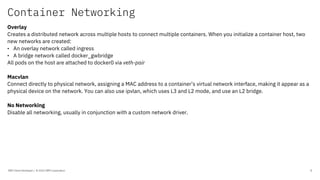
  • 8. Container Networking IBM Client Developer / © 2020 IBM Corporation 8 Overlay Creates a distributed network across multiple hosts to connect multiple containers. When you initialize a container host, two new networks are created: • An overlay network called ingress • A bridge network called docker_gwbridge All pods on the host are attached to docker0 via veth-pair Macvlan Connect directly to physical network, assigning a MAC address to a container’s virtual network interface, making it appear as a physical device on the network. You can also use ipvlan, which uses L3 and L2 mode, and use an L2 bridge. No Networking Disable all networking, usually in conjunction with a custom network driver.
  • 9. Container Network Interface (CNI) IBM Client Developer / © 2020 IBM Corporation 9 CNI is a vendor-neutral interface between container runtimes and networks, independent of the Container Orchestration (CO) platform, e.g. Kubernetes, OpenShift, Docker, rkt, Mesos, CloudFoundry, podman, CRI-O, Kurma, Amazon ECS. CNI (Container Network Interface) originates at CoreOS as part of rkt. Now a CNCF project. CNI is responsible for network connectivity of containers and removing allocated resources when the container is deleted. It consists of a specification and libraries for writing plugins to configure network interfaces. CNI defines a basic execution flow and JSON-based configuration format for network operations. Plugins are executables in the host, and Kubelet is the runtime on the node. The container runtime creates the Network Namespace, identifies the network to attach containers, and invokes the plugin. The CNI plugin or bridge program implements: 1. Create veth Pairs 2. Create Bridge Network/Interface 3. Attach vEth to Namespace 4. Attach other vEth to Bridge 5. Assign IP address 6. Bring up interfaces 7. Enable NAT Basic plugin commands: • ADD • DEL • CHECK • VERSION E.g. the container runtime invokes `bridge add <cid> <namespace>` to add a container to a network.
  • 10. Container Network Interface (CNI) IBM Client Developer / © 2020 IBM Corporation 10 Container Networking is based for a large part on Linux networking. Multi-networking CNI supports multi-networking, but Kubernetes by default does not: a Kubernetes pod is exposed only to 1 interface (and loopback). Multus by Intel supports multi-networking using CRD-based network objects. Reference plugins: bridge, loopback, vlan, macvlan, ipvlan, host-device, ptp (point-to-point), Windows bridge, Windows overlay. IPAM (IP Address Management): host-local, DHCP, static Meta (chained) plugins: bandwidth, firewall, flannel, portmap, source-based routing, tuning 3rd Party plugins: Calico, Weave, Cilium, Multus, Romana, SR-IOV (Single Root I/O Virtualization), Nuage, Amazon ECS, Linen, Silk (CF) * IBM Cloud Kubernetes implements Calico * OpenShift supports using SR-IOV hardware on nodes
  • 11. Container Network Model (CNM) IBM Client Developer / © 2020 IBM Corporation 11 Aka Libnetwork supported by Docker https://github.com/docker/libnetwork
  • 12. Kubernetes Architecture IBM Client Developer / © 2020 IBM Corporation 12 • At its core, Kubernetes is a database (etcd) with "watchers" and "controllers" that react to changes in etcd, etcd is a consensus database using Raft • The kube-api-server is an API server that exposes the Kubernetes API, all traffic goes through the API Server • The kube-scheduler watches for new Pods not assigned to a node and selects a node to run the Pod on, • The kube-controller-manager runs the controller loops that make Kubernetes, • The cloud-controller-manager interacts with the underlying cloud provider, • The etcd key-value store represents the user defined desired state of the objects, • The kubelet makes sure that containers are running in a Pod, • The kube-proxy is a network proxy that maintains network rules on nodes,
  • 13. API Server IBM Client Developer / © 2020 IBM Corporation 13 The control plane on the master node(s) consists of the API Server, the Controller Manager and Schedulers. The API Server is the only component that talks directly to etcd and is a gateway to etcd, which is the consensus database for the state of your application cluster. The API Server: • Serves the Kubernetes API, • Proxies cluster components such as the Kubernetes UI, • Allows manipulation of the state of objects, • Persists the state of objects in etcd. https://www.openshift.com/blog/kubernetes-deep-dive-api-server-part-1
  • 14. API Server IBM Client Developer / © 2020 IBM Corporation 14 Workflow: 1. Transport security: API Server is accessed via port 443 protected by TLS and it presents a certificate. 2. Authentication: running 1 or more authentication modules (client certificates, password, plain tokens, bootstrap tokens, JSON web tokens) 3. Authorization: request must include username, action and target object, and is verified against a policy. Multiple authorization modules are supported: ABAC, RBAC, Webhook. 4. Admission Controller: modify or reject requests, does not effect reads. source: https://kubernetes.io/docs/concepts/security/controlling-access/
  • 15. Request Flow IBM Client Developer / © 2020 IBM Corporation 15 The API Server handles requests from within and to outside the cluster. When an HTTP request hits the Kubernetes API: • HTTP request is processed by a chain of Filters registered in DefaultBuildHandlerChain(). Either the filter passes and attaches respective info to ctx.RequestInfo, such as authenticated user or returns an appropriate HTTP response code. • Next, the Multiplexer or MUX routes the HTTP request to the respective handler, depending on the HTTP path. • The Routes (as defined in routes/*) connect handlers with HTTP paths. • The handler takes the HTTP Request and Context (like user, rights, etc.) and delivers the requested object from storage. https://www.openshift.com/blog/kubernetes-deep-dive-api-server-part-1
  • 16. Admission Controller IBM Client Developer / © 2020 IBM Corporation 16 An admission controller is a piece of code that intercepts requests to the Kubernetes API server prior to persistence of the object, but after the request is authenticated and authorized. The admission control process has two phases: a mutating phase and validating phase. The controllers are compiled into the kube-apiserver binary. Examples of default admission controllers: AlwaysAdmit, AlwaysPullImages, AlwaysDeny, CertificateApproval, CertificateSigning, DefaultStorageClass, EventRateLimit, NameSpaceLifecycle, NodeRestriction, PodNodeSelector, PersistentVolumeClaimResize, PodSecurityPolicy, ResourceQuota, ServiceAccount among more than 30, and 2 webhooks with a special role: MutatingAdmissionWebhook and ValidatingAdmissionWebhook. The webhooks do not implement any policy logic themselves, but is obtained from a REST endpoint. This approach decouples the admission controller logic from the Kubernetes API server, allowing custom logic to be executed whenever resources are created, updated, or deleted in a Kubernetes cluster. The webhook handles an AdmissionReview request sent by the API Server and sends back a decision in the same AdmissionReview it received. OpenShift Container Platform (OCP) has a default set of admission plug-ins enabled for each resource type.
  • 17. Kubernetes Networking IBM Client Developer / © 2020 IBM Corporation 17 • All pods can communicate with all pods without NAT • All nodes can communicate with all pods without NAT • The IP of the pod is the same for itself as it is for others 4 networking problems remain: • Container to container • Pod to pod • Pod to service • Internet to service VM Typically, network communication on a VM interacts with an Ethernet device. In Linux, that network communication runs within a network namespace with its own logical networking stack with its own routes, firewall rules, and network devices. Container to container A pod is a group of containers that share a network namespace, they all have the same IP address and port space assigned and can find each other via localhost. Containers join the network namespace with the --net=container: function. Containers within a pod also can access shared volumes, which are part of the pod and available to be mounted into the applications filesystem. A pod exists in its own Ethernet namespace. VM root network namespace eth0 VM root network namespace eth0 Pod 1 ns Pod 2 ns ctr1 ctr2 ctr1 ctr2
  • 18. Kubernetes Networking IBM Client Developer / © 2020 IBM Corporation 18 Pod to pod A pod exists in its own Ethernet namespace that needs to communicate with other network namespaces on the same node. Pods or Namespaces can be connected using a Linux Virtual Ethernet Device or veth pair, consisting of two virtual interfaces across multiple namespaces. One side of the veth pair is connected to the root network namespace, and the other side to the Pod’s network namespace. This setup can be replicated for all pods on the VM. The veth connects a pod namespace to the root namespace. A bridge connects pod namespaces. A Linux Ethernet bridge is a virtual Layer 2 (L2) networking device to connect two networks by maintaining a forwarding table between sources and destinations by examining the destination of the data packets and looking at the MAC-address of each Ethernet device in the network. Bridges implement the ARP protocol to discover the link-layer MAC address associated with an IP address. The bridge broadcasts the data frame out to connected devices except the sender and the device that responds to the frame is stored in a lookup table. But the Kubernetes networking model dictates that pods can reach pods by their IP address across nodes. Generally, every Node in your cluster is assigned a CIDR block specifying the IP addresses available to Pods running on that Node. Once traffic destined for the CIDR block reaches the Node it is the Node’s responsibility to forward traffic to the correct Pod. On failure to find the correct MAC address, the bridge sends the packet out the default route — the root namespace’s eth0 device. At this point the route leaves the Node and enters the network. The network routes the packet to the correct Node based on the CIDR block assigned to the Node. How this is done is network specific. The Container Networking Interface (CNI) provides a common API for connecting containers to the outside network. VM root netns eth0 Pod 1 ns Pod 2 ns veth0 veth1 eth0 eth0 VM eth0 Pod 1 ns Pod 2 ns veth0 veth1 eth0 eth0 root netns cbr0
  • 19. Service IBM Client Developer / © 2020 IBM Corporation 19 The connection for Pod to service and Internet to service is handled by Kubernetes Service types. The Service object is an abstraction of a logical set of Pods exposed through Endpoints that are updated whenever the set of Pods in a Service change. Every Service defined in the cluster is assigned a DNS name that maps to the ClusterIP of the Service. Kubelets on nodes in the cluster are configured to use the IP of the DNS Service to resolve DNS names for Service Discovery. The Endpoints for a set of pods are determined using a Selector. Labels are key/value pairs that are attached to objects can be used to organize and select subsets of objects. The label selector is the core grouping primitive in Kubernetes. Service types: • ClusterIP, default Service type that exposes the service on a cluster-internal IP only. • NodePort, exposes the service on each Node’s IP at a static port (the NodePort). A ClusterIP service, to which the NodePort service will route, is automatically created. • LoadBalancer, on top of a NodePort and ClusterIP, exposes the service externally using a cloud provider’s load balancer. • ExternalName, maps the service to the externalName field (e.g. foo.bar.example.com) by returning a CNAME record with its value. • Ingress • Route
  • 20. Ingress IBM Client Developer / © 2020 IBM Corporation 20 An Ingress resource manages external access to the services in a cluster, typically HTTP/HTTPS. Ingress can also provide load balancing, TLS termination and name-based virtual hosting. Ingress consists of an Ingress API object and the Ingress Controller. The Ingress Controller implements the Ingress API. The Ingress Controller is usually a load balancer for routing external traffic to your Kubernetes cluster and is responsible for L4-L7 Network Services. Ingress consists of three components: • Ingress resources, • L7 Application Load Balancer (ALB), • An external L4 load balancer to handle incoming requests across zones, depending on the provider. To expose an app by using Ingress, you must create a Kubernetes service for your app and register this service with Ingress by defining an Ingress resource. The Ingress resource is a Kubernetes resource that defines the rules for how to route incoming requests for apps. source: https://cloud.ibm.com/docs/containers?topic=containers-ingress-about apiVersion: networking.k8s.io/v1beta1 kind: Ingress spec: backend: serviceName: helloworld servicePort: 8080
  • 21. Service IBM Client Developer / © 2020 IBM Corporation 21
  • 22. Ingress Application Load Balancer (ALB) IBM Client Developer / © 2020 IBM Corporation 22 The Ingress Application Load Balancer (ALB) is a layer 7 (L7) load balancer which implements the NGINX Ingress controller. A layer 4 (L4) LoadBalancer service exposes the ALB so that the ALB can receive external requests that come into your cluster. The Application Load Balancer (ALB) is an external load balancer that listens for incoming HTTP, HTTPS, or TCP service requests. The ALB then forwards requests to the appropriate app according to the rules defined in the Ingress resource. When you create a standard cluster, IBM Cloud Kubernetes Service automatically creates a highly available ALB in each zone where you have worker nodes. In classic clusters, the Ingress subdomain for your cluster is linked to the public ALB IP addresses. For classic clusters, the ALB is a Multi-Zone Load Balancer (MZLB) that IBM Cloud Kubernetes Service creates for you. In a VPC cluster, one public VPC load balancer is automatically created outside of your cluster in your VPC. The public VPC load balancer puts the public IP addresses of your public ALBs behind one hostname. In VPC clusters, a hostname is assigned to the ALBs because the ALB IP addresses are not static. This ALB hostname is different than the Ingress subdomain. The services that expose your ALBs on public or private IP addresses are formatted as public-abc12 in the kube-system namespace. The Kubernetes Ingress image is built on the community Kubernetes project's implementation of the NGINX Ingress controller. The Kubernetes Ingress controller image is now supported for Ingress ALBs, and all new ALBs run the Kubernetes Ingress image by default. source: https://cloud.ibm.com/docs/containers?topic=containers-ingress-about
  • 23. Ingress Application Load Balancer (ALB) IBM Client Developer / © 2020 IBM Corporation 23 ibmcloud ks ingress secret create --cluster <cluster_name> --cert-crn <CRN> --name <secret_name> -- namespace <namespace> apiVersion: networking.k8s.io/v1beta1 # For Kubernetes version 1.19, use networking.k8s.io/v1 instead kind: Ingress metadata: name: community-ingress-resource annotations: kubernetes.io/ingress.class: "<public|private>-iks-k8s-nginx" spec: tls: - hosts: - <domain> secretName: <tls_secret_name> rules: - host: <domain> http: paths: - path: /<app1_path> backend: serviceName: <app1_service> servicePort: 80 - path: /<app2_path> backend: serviceName: <app2_service> servicePort: 80 kubectl apply -f ingress-resource.yaml -n <namespace>
  • 24. Route IBM Client Developer / © 2020 IBM Corporation 24 The Route is an OpenShift resource that was created before the Ingress was added to Kubernetes. Route also enables external access to services with additional capabilities like splitting traffic between multiple backends, sticky sessions. Route principles heavily influenced the Ingress design. When a Route object is created on OpenShift the built-in HAProxy load balancer exposes the requested service and makes it externally available. Routes are assigned a hostname from the router subdomain that external clients can use to send requests to your app. OpenShift offers 4 types of routes: • Simple, to handle non-encrypted HTTP traffic, • Passthrough, to pass TLS connections without interruption to the pod, no TLS termination, • Edge, to handle encrypted HTTPS traffic for non- encrypted HTTP endpoints, • Re-encrypt, uses TLS termination and new TLS connection between router and pod. source: https://cloud.ibm.com/docs/openshift?topic=openshift-openshift_routes
  • 25. DNS Server IBM Client Developer / © 2020 IBM Corporation 25 The Kubernetes DNS server watches the Kubernetes API for new Services and changes. It creates a set of DNS records for each service. Kubernetes DNS schedules a DNS Pod and Service on the cluster, and configures the kubelets to tell individual containers to use the DNS Service's IP to resolve DNS names. Pods can resolve Services by their DNS name. In Kubernetes version 1.11 and later, CoreDNS is recommended and installed by default with kubeadm. CoreDNS is a DNS server written in Go. There are currently about 30 plugins included in the default CoreDNS install, as well as external plugins. When a query is processed by CoreDNS, the following steps are performed with the request: - Route request to the closest zone and port, - Route request through the static plugin chain, - Each plugin inspects the request and determines if it should process the request, processing means responding to client. Kubernetes also supports DNS SRV (DNS Service) records for named ports. If the `my-service.my-ns` Service has a port named "http" with the protocol set to TCP, you can do a DNS SRV query for `_http._tcp.my-service.my-ns` to discover the port number for `http` as well as the IP address. The Kubernetes DNS server is the only way to access ExternalName Services. DNS policies can be set per pod via the `dnsPolicy` field: Default (inherit from node), ClusterFirst (default, forward to upstream nameserver), ClusterFirstWithHostNet, None. The `dnsConfig` field on a Pod, allows you control on DNS settings for a Pod: nameservers, searches, options.
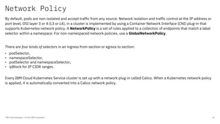
  • 26. Network Policy IBM Client Developer / © 2020 IBM Corporation 26 By default, pods are non-isolated and accept traffic from any source. Network isolation and traffic control at the IP address or port level, OSI layer 3 or 4 (L3 or L4), in a cluster is implemented by using a Container Network Interface (CNI) plug-in that supports Kubernetes network policy. A NetworkPolicy is a set of rules applied to a collection of endpoints that match a label selector within a namespace. For non-namespaced network policies, use a GlobalNetworkPolicy. There are four kinds of selectors in an ingress from section or egress to section: • podSelector, • namespaceSelector, • podSelector and namespaceSelector, • ipBlock for IP CIDR ranges. Every IBM Cloud Kubernetes Service cluster is set up with a network plug-in called Calico. When a Kubernetes network policy is applied, it is automatically converted into a Calico network policy.
  • 27. Network Policy IBM Client Developer / © 2020 IBM Corporation 27 apiVersion: networking.k8s.io/v1 kind: NetworkPolicy metadata: name: helloworld-deny-all spec: podSelector: {} policyTypes: - Ingress - Egress apiVersion: networking.k8s.io/v1 kind: NetworkPolicy metadata: name: allow-helloworld spec: policyTypes: - Ingress podSelector: matchLabels: app: helloworld ingress: - {}
  • 28. Security Context IBM Client Developer / © 2020 IBM Corporation 28 A security context defines privilege and access control settings for a Pod or Container. Security context settings include, but are not limited to: • Discretionary Access Control (DAC), • Security Enhanced Linux (SELinux), • Linux Capabilities, • Seccomp, • SecurityContextConstraint (SCC), ServiceAccount (SA), and Role Based Access Control (RBAC),
  • 29. Pod Security Policy IBM Client Developer / © 2020 IBM Corporation 29 Pod Security Policies enable fine-grained authorization of pod creation and updates. A Pod Security Policy is a cluster-level resource that controls security of the pod specification. The PodSecurityPolicy object defines a set of conditions that a pod must run. PodSecurityPolicies are implemented as an admission controller.
  • 30. Group Name / DOC ID / Month XX, 2018 / © 2018 IBM Corporation 30