SlideShare a Scribd company logo
A Seminar On:

Line Coding


 Presented by:
Miss Rina Ahire
  ME(ETC)


                  1
Objectives:
•Need of Line Coding
•Introduction of Line Coding
•Properties of Line Coding
•Types of Line Coding
•Advantages and Disadvantages
•Power Spectral Density
• PSD of Line Coding
•Comparison of Line Coding


                                2
Need Of Line Coding:

•Various Techniques

•Other Way: From Computers

•Information: Inherently discrete in nature

•Transmitted over band-limited channel: Signal gets Dispersed

•Causes: Overlap and Distortion

•Distortion: Intersymbol Interference(ISI)                3
To avoid all these problems we are going for


             Line Coding


                                               4
Introduction:
•Binary Data: Pulses

•Line Coding: A pair of pulses to represent symbols 1 and 0


                                                              5
Properties of Line Coding:

•Transmission Bandwidth: as small as possible

• Power Efficiency: As small as possible for given BW and
  probability of error

• Error Detection and Correction capability: Ex: Bipolar

• Favorable power spectral density: dc=0

• Adequate timing content: Extract timing from pulses

• Transparency: Prevent long strings of 0s or 1s            6
Types of Line Coding:


                        7
Unipolar Signaling:

•On-Off keying ie OOK

•Pulse 0: Absence of pulse

•Pulse1 : Presence of pulse

There are two common variations of unipolar signalling:
1. Non-Return to Zero (NRZ)
2. Return to Zero (RZ)

                                                          8
Unipolar Non-Return to Zero (NRZ):

•Duration of the MARK pulse (Ƭ ) is equal to the duration (To) of
the symbol slot.


                                                               9
Advantages:
•Simplicity in implementation
• Doesn‟t require a lot of bandwidth for transmission.

Disadvantages:
•Presence of DC level (indicated by spectral line at 0 Hz).
•Contains low frequency components. Causes “Signal Droop”
•Does not have any error correction capability.
•Does not posses any clocking component for ease of
synchronisation.
•Is not Transparent. Long string of zeros causes loss of
synchronisation.

                                                         10
Unipolar Return to Zero (RZ):

•MARK pulse (Ƭ ) is less than the duration (To) of the symbol slot.
•Fills only the first half of the time slot, returning to zero for the
second half.


                                                                  11
Advantages:
•Simplicity in implementation.
•Presence of a spectral line at symbol rate which can be used as
symbol timing clock signal.

Disadvantages:
•Presence of DC level (indicated by spectral line at 0 Hz).
•Continuous part is non-zero at 0 Hz. Causes “Signal Droop”.
•Does not have any error correction capability.
•Occupies twice as much bandwidth as Unipolar NRZ.
•Is not Transparent


                                                               12
Polar Signalling:
•Polar RZ
•Polar NRZ

Polar NRZ:
•A binary 1 is represented by a pulse g1(t)
•A binary 0 by the opposite (or antipodal) pulse g0(t) = -g1(t).


                                                                   13
Advantages:
•Simplicity in implementation.
•No DC component.

Disadvantages:
•Continuous part is non-zero at 0 Hz. Causes “Signal Droop”.
•Does not have any error correction capability.
•Does not posses any clocking component for ease of
synchronisation.
•Is not transparent.


                                                        14
Polar RZ:
•A binary 1: A pulse g1(t)
•A binary 0: The opposite (or antipodal) pulse g0(t) = -g1(t).
•Fills only the first half of the time slot, returning to zero for the
second half.


                                                                         15
Advantages:
•Simplicity in implementation.
•No DC component.

Disadvantages:
•Continuous part is non-zero at 0 Hz. Causes “Signal Droop”.
•Does not have any error correction capability.
•Occupies twice as much bandwidth as Polar NRZ.


                                                               16
Bipolar Signalling:

•Alternate mark inversion (AMI)

•Uses three voltage levels (+V, 0, -V)

•0: Absence of a pulse

•1: Alternating voltage levels of +V and –V


                                              17
Bipolar NRZ:


Bipolar RZ:


               18
Advantages:
•No DC component.
•Occupies less bandwidth than unipolar and polar NRZ schemes.
•Does not suffer from signal droop (suitable for transmission over
AC coupled lines).
•Possesses single error detection capability.

Disadvantages:
•Does not posses any clocking component for ease of
synchronisation.
•Is not Transparent.

                                                              19
Manchester Signalling:
•The duration of the bit is divided into two halves
•A „One‟ is +ve in 1st half and -ve in 2nd half.
•A „Zero‟ is -ve in 1st half and +ve in 2nd half.


                                                      20
Advantages:
•No DC component.
•Does not suffer from signal droop (suitable for transmission over
AC coupled lines).
•Easy to synchronise.
•Is Transparent.

Disadvantages:
•Because of the greater number of transitions it occupies a
significantly large bandwidth.
•Does not have error detection capability.


                                                              21
Power Spectral Density:
•The function which gives distribution of power of a signal at
various frequencies in frequency domain.

•PSD is the Fourier Transform of autocorrelation

•Rectangular pulse and its spectrum


                                                                 22
PSD Derivation:
• We now need to derive the time autocorrelation of a power
signal x(t)
                              _--

• Since x(t) consists of impulses,    is found by


• Recognizing        for real signals, we have


                                                              23
•Since the pulse filter has the spectrum of         , we have


• Now, we can use this to find the PSD of various line codes.


                                                                24
PSD of Polar Signalling:
• In polar signalling,
      Binary “1” is transmitted by a pulse f(t)
      Binary “0” is transmitted by a pulse –f(t)
• In this case,     is equally likely to be 1 or -1 and              is always 1.


      Where, There are N pulses and       for each one.
             The summation on the right-hand side of the above equation is N.
• Moreover, both and               are either 1 or -1. So,              is either 1
or -1.
  They are equally likely to be 1 or -1 on the average, out of N terms the product
  is equal to 1 for N/2 terms and is equal to -1 for the remaining N/2 terms.


                                                                                     25
PSD of Bipolar Signalling:
•To calculate the PSD, we have


•On the average, half of the     are 0, and the remaining half are
 either 1 or -1, with      . Therefore,


                                                                 26
•To compute R1, we consider the pulse strength product                    .
       -Four possible equally likely sequences of two bits:11,10,01,00.
       -Since bit 0 encoded by no pulse        , the product          for
        the last three of these sequences. This means that, on the average,
        3N/4 combinations have             and only N/4 combinations have
        non zero        . Because of the bipolar rule, the bit sequence 11
        can only be encoded by two consecutive pulse of opposite
        polarities. This means the product            for the N/4
        combinations.


                                                                              27
PSD of Lines Codes:


                      28
Comparison of Line Codes:
 Sr.      Parameters         Polar RZ   Polar NRZ     AMI       Manchester
 No.

 1     Transmission of DC   YES         YES         NO          NO
       component
 2     Signaling Rate       1/Tb        1/Tb        1/Tb        1/Tb

 3     Noise Immunity       LOW         LOW         HIGH        HIGH

 4     Synchronizing        Poor        Poor        Very Good   Very Good
       Capability
 5     Bandwidth Required   1/Tb        1/2Tb       1/2Tb       1/Tb

 6     Crosstalk            HIGH        HIGH        LOW         LOW


                                                                             29
Thank You


            30

More Related Content

What's hot (20)

PDF
Types of line coding
ramalakshmi54
 
PDF
Multiplexing
Aman Jaiswal
 
PPTX
M ary psk modulation
Ahmed Diaa
 
PDF
Diversity Techniques in Wireless Communication
Sahar Foroughi
 
PDF
ASK,FSK and M-PSK using Matlab
Amirah Nadrah Ghazali
 
PPTX
M ary psk and m ary qam ppt
DANISHAMIN950
 
PPTX
Digital Modulation Techniques ppt
Pankaj Singh
 
PDF
Line coding
Ravindra Rathore
 
PDF
Telecommunication switching system
Madhumita Tamhane
 
PPTX
Butterworth filter
MOHAMMAD AKRAM
 
PPTX
Delta modulation
mpsrekha83
 
PDF
Data Communication & Computer Networks : Serial and parellel transmission
Dr Rajiv Srivastava
 
PDF
Companding & Pulse Code Modulation
Yeshudas Muttu
 
PDF
Line codes
Madhumita Tamhane
 
PDF
Two cavity klystron
abhikalmegh
 
PPTX
Pulse code modulation (PCM)
Mahima Shastri
 
PDF
Pulse Code Modulation (PCM)
Arun c
 
PPTX
Double sideband suppressed carrier (dsb sc) modulation
Quaid i Azam university Islamabad
 
PPT
Digital Communication: Information Theory
Dr. Sanjay M. Gulhane
 
PPTX
Ec 2401 wireless communication unit 2
JAIGANESH SEKAR
 
Types of line coding
ramalakshmi54
 
Multiplexing
Aman Jaiswal
 
M ary psk modulation
Ahmed Diaa
 
Diversity Techniques in Wireless Communication
Sahar Foroughi
 
ASK,FSK and M-PSK using Matlab
Amirah Nadrah Ghazali
 
M ary psk and m ary qam ppt
DANISHAMIN950
 
Digital Modulation Techniques ppt
Pankaj Singh
 
Line coding
Ravindra Rathore
 
Telecommunication switching system
Madhumita Tamhane
 
Butterworth filter
MOHAMMAD AKRAM
 
Delta modulation
mpsrekha83
 
Data Communication & Computer Networks : Serial and parellel transmission
Dr Rajiv Srivastava
 
Companding & Pulse Code Modulation
Yeshudas Muttu
 
Line codes
Madhumita Tamhane
 
Two cavity klystron
abhikalmegh
 
Pulse code modulation (PCM)
Mahima Shastri
 
Pulse Code Modulation (PCM)
Arun c
 
Double sideband suppressed carrier (dsb sc) modulation
Quaid i Azam university Islamabad
 
Digital Communication: Information Theory
Dr. Sanjay M. Gulhane
 
Ec 2401 wireless communication unit 2
JAIGANESH SEKAR
 

Viewers also liked (6)

PPTX
Mesh topology
coolsdq
 
PPT
Line coding
srkrishna341
 
PPT
1432.encoding concepts
techbed
 
PPTX
Line coding
Gagan Randhawa
 
PPT
PULSE CODE MODULATION (PCM)
vishnudharan11
 
Mesh topology
coolsdq
 
Line coding
srkrishna341
 
1432.encoding concepts
techbed
 
Line coding
Gagan Randhawa
 
PULSE CODE MODULATION (PCM)
vishnudharan11
 
Ad

Similar to Line coding (20)

PPTX
Sonjoy kundu 007
Sonjoy Kundu
 
PPTX
Sonjoy kundu line coding
Sonjoy Kundu
 
PPTX
Line coding
VaibhavSinha39
 
PPT
LineCoding_ADCS.ppt
AbdullahOmar64
 
PPT
Line coding adcs
Sohail Kakar
 
PPTX
Unipolar
Roshan Chaudhary
 
PPTX
Digital data transmission,line coding and pulse shaping
Aayush Kumar
 
PDF
Linecodingstudent 140716233501-phpapp01
Gita Patil
 
PPT
Chap4 d t-d conversion
arslan_akbar90
 
PDF
05 signal encoding
Praveen Kumar
 
PDF
Chapter4
mailtonagaraju
 
PPT
est your knowledge of digital communication systems with our interactive quiz...
NanaAgyeman13
 
PDF
Unipolar Encoding Techniques: NRZ & RZ
Arunabha Saha
 
DOCX
Line coding
Sazzad Hossain Fahad
 
PPT
base-band_digital_data_transmission-Line coding - Copy.ppt
AbyThomas54
 
PPTX
Encoding techniques
Goriha Naveed
 
PPTX
Encoding Techniques
Goriha Naveed
 
PDF
Digital Data, Digital Signal | Scrambling Techniques
Biplap Bhattarai
 
PPTX
DC_PPT.pptx
RahulAgarwal505237
 
Sonjoy kundu 007
Sonjoy Kundu
 
Sonjoy kundu line coding
Sonjoy Kundu
 
Line coding
VaibhavSinha39
 
LineCoding_ADCS.ppt
AbdullahOmar64
 
Line coding adcs
Sohail Kakar
 
Digital data transmission,line coding and pulse shaping
Aayush Kumar
 
Linecodingstudent 140716233501-phpapp01
Gita Patil
 
Chap4 d t-d conversion
arslan_akbar90
 
05 signal encoding
Praveen Kumar
 
Chapter4
mailtonagaraju
 
est your knowledge of digital communication systems with our interactive quiz...
NanaAgyeman13
 
Unipolar Encoding Techniques: NRZ & RZ
Arunabha Saha
 
base-band_digital_data_transmission-Line coding - Copy.ppt
AbyThomas54
 
Encoding techniques
Goriha Naveed
 
Encoding Techniques
Goriha Naveed
 
Digital Data, Digital Signal | Scrambling Techniques
Biplap Bhattarai
 
DC_PPT.pptx
RahulAgarwal505237
 
Ad

Line coding

  • 1. A Seminar On: Line Coding Presented by: Miss Rina Ahire ME(ETC) 1
  • 2. Objectives: •Need of Line Coding •Introduction of Line Coding •Properties of Line Coding •Types of Line Coding •Advantages and Disadvantages •Power Spectral Density • PSD of Line Coding •Comparison of Line Coding 2
  • 3. Need Of Line Coding: •Various Techniques •Other Way: From Computers •Information: Inherently discrete in nature •Transmitted over band-limited channel: Signal gets Dispersed •Causes: Overlap and Distortion •Distortion: Intersymbol Interference(ISI) 3
  • 4. To avoid all these problems we are going for Line Coding 4
  • 5. Introduction: •Binary Data: Pulses •Line Coding: A pair of pulses to represent symbols 1 and 0 5
  • 6. Properties of Line Coding: •Transmission Bandwidth: as small as possible • Power Efficiency: As small as possible for given BW and probability of error • Error Detection and Correction capability: Ex: Bipolar • Favorable power spectral density: dc=0 • Adequate timing content: Extract timing from pulses • Transparency: Prevent long strings of 0s or 1s 6
  • 7. Types of Line Coding: 7
  • 8. Unipolar Signaling: •On-Off keying ie OOK •Pulse 0: Absence of pulse •Pulse1 : Presence of pulse There are two common variations of unipolar signalling: 1. Non-Return to Zero (NRZ) 2. Return to Zero (RZ) 8
  • 9. Unipolar Non-Return to Zero (NRZ): •Duration of the MARK pulse (Ƭ ) is equal to the duration (To) of the symbol slot. 9
  • 10. Advantages: •Simplicity in implementation • Doesn‟t require a lot of bandwidth for transmission. Disadvantages: •Presence of DC level (indicated by spectral line at 0 Hz). •Contains low frequency components. Causes “Signal Droop” •Does not have any error correction capability. •Does not posses any clocking component for ease of synchronisation. •Is not Transparent. Long string of zeros causes loss of synchronisation. 10
  • 11. Unipolar Return to Zero (RZ): •MARK pulse (Ƭ ) is less than the duration (To) of the symbol slot. •Fills only the first half of the time slot, returning to zero for the second half. 11
  • 12. Advantages: •Simplicity in implementation. •Presence of a spectral line at symbol rate which can be used as symbol timing clock signal. Disadvantages: •Presence of DC level (indicated by spectral line at 0 Hz). •Continuous part is non-zero at 0 Hz. Causes “Signal Droop”. •Does not have any error correction capability. •Occupies twice as much bandwidth as Unipolar NRZ. •Is not Transparent 12
  • 13. Polar Signalling: •Polar RZ •Polar NRZ Polar NRZ: •A binary 1 is represented by a pulse g1(t) •A binary 0 by the opposite (or antipodal) pulse g0(t) = -g1(t). 13
  • 14. Advantages: •Simplicity in implementation. •No DC component. Disadvantages: •Continuous part is non-zero at 0 Hz. Causes “Signal Droop”. •Does not have any error correction capability. •Does not posses any clocking component for ease of synchronisation. •Is not transparent. 14
  • 15. Polar RZ: •A binary 1: A pulse g1(t) •A binary 0: The opposite (or antipodal) pulse g0(t) = -g1(t). •Fills only the first half of the time slot, returning to zero for the second half. 15
  • 16. Advantages: •Simplicity in implementation. •No DC component. Disadvantages: •Continuous part is non-zero at 0 Hz. Causes “Signal Droop”. •Does not have any error correction capability. •Occupies twice as much bandwidth as Polar NRZ. 16
  • 17. Bipolar Signalling: •Alternate mark inversion (AMI) •Uses three voltage levels (+V, 0, -V) •0: Absence of a pulse •1: Alternating voltage levels of +V and –V 17
  • 19. Advantages: •No DC component. •Occupies less bandwidth than unipolar and polar NRZ schemes. •Does not suffer from signal droop (suitable for transmission over AC coupled lines). •Possesses single error detection capability. Disadvantages: •Does not posses any clocking component for ease of synchronisation. •Is not Transparent. 19
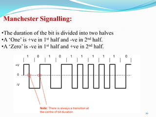
  • 20. Manchester Signalling: •The duration of the bit is divided into two halves •A „One‟ is +ve in 1st half and -ve in 2nd half. •A „Zero‟ is -ve in 1st half and +ve in 2nd half. 20
  • 21. Advantages: •No DC component. •Does not suffer from signal droop (suitable for transmission over AC coupled lines). •Easy to synchronise. •Is Transparent. Disadvantages: •Because of the greater number of transitions it occupies a significantly large bandwidth. •Does not have error detection capability. 21
  • 22. Power Spectral Density: •The function which gives distribution of power of a signal at various frequencies in frequency domain. •PSD is the Fourier Transform of autocorrelation •Rectangular pulse and its spectrum 22
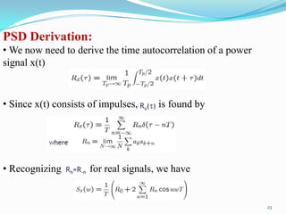
  • 23. PSD Derivation: • We now need to derive the time autocorrelation of a power signal x(t) _-- • Since x(t) consists of impulses, is found by • Recognizing for real signals, we have 23
  • 24. •Since the pulse filter has the spectrum of , we have • Now, we can use this to find the PSD of various line codes. 24
  • 25. PSD of Polar Signalling: • In polar signalling, Binary “1” is transmitted by a pulse f(t) Binary “0” is transmitted by a pulse –f(t) • In this case, is equally likely to be 1 or -1 and is always 1. Where, There are N pulses and for each one. The summation on the right-hand side of the above equation is N. • Moreover, both and are either 1 or -1. So, is either 1 or -1. They are equally likely to be 1 or -1 on the average, out of N terms the product is equal to 1 for N/2 terms and is equal to -1 for the remaining N/2 terms. 25
  • 26. PSD of Bipolar Signalling: •To calculate the PSD, we have •On the average, half of the are 0, and the remaining half are either 1 or -1, with . Therefore, 26
  • 27. •To compute R1, we consider the pulse strength product . -Four possible equally likely sequences of two bits:11,10,01,00. -Since bit 0 encoded by no pulse , the product for the last three of these sequences. This means that, on the average, 3N/4 combinations have and only N/4 combinations have non zero . Because of the bipolar rule, the bit sequence 11 can only be encoded by two consecutive pulse of opposite polarities. This means the product for the N/4 combinations. 27
  • 28. PSD of Lines Codes: 28
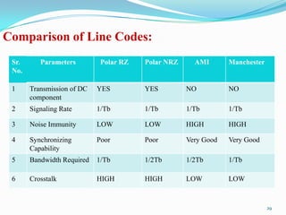
  • 29. Comparison of Line Codes: Sr. Parameters Polar RZ Polar NRZ AMI Manchester No. 1 Transmission of DC YES YES NO NO component 2 Signaling Rate 1/Tb 1/Tb 1/Tb 1/Tb 3 Noise Immunity LOW LOW HIGH HIGH 4 Synchronizing Poor Poor Very Good Very Good Capability 5 Bandwidth Required 1/Tb 1/2Tb 1/2Tb 1/Tb 6 Crosstalk HIGH HIGH LOW LOW 29
  • 30. Thank You 30