LTE Measurement: How to test a device
50 likes•31,088 views

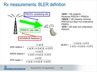
The document outlines the testing and measurement protocols for LTE and UMTS mobile communications, detailing RF testing requirements for both user and base stations. Key aspects include power control, transmit signal quality, receiver characteristics, and specific regional requirements for various LTE bands. Additionally, it discusses the performance metrics and methods for assessing unwanted emissions, including adjacent channel leakage and spurious emissions.


![LTE bands and channel bandwidth
E-UTRA band / channel bandwidth
E-UTRA Band
1.4 MHz 3 MHz 5 MHz 10 MHz 15 MHz 20 MHz
1 Yes Yes Yes Yes
2 Yes Yes Yes Yes Yes[1] Yes[1]
3 Yes Yes Yes Yes Yes[1] Yes[1]
4 Yes Yes Yes Yes Yes Yes
5 Yes Yes Yes Yes[1]
6 Yes Yes[1]
7 Yes Yes Yes Yes[1]
8 Yes Yes Yes Yes[1]
9 Yes Yes Yes[1] Yes[1]
10 Yes Yes Yes Yes
11 Yes Yes[1]
12 Yes Yes Yes[1] Yes[1]
13
14
Yes[1]
Yes[1]
Yes[1]
Yes[1]
Not every channel
...
17 Yes[1] Yes[1]
bandwidth for
... every band!
33 Yes Yes Yes Yes
34 Yes Yes Yes
35 Yes Yes Yes Yes Yes Yes
36 Yes Yes Yes Yes Yes Yes
37 Yes Yes Yes Yes
38 Yes Yes Yes Yes
39 Yes Yes Yes Yes
40 Yes Yes Yes Yes
NOTE 1: bandwidth for which a relaxation of the specified UE receiver sensitivity requirement (Clause 7.3) is allowed.
November 2012 | LTE measurements| 13](https://image.slidesharecdn.com/lteeutranrsanov2012day2-121031161327-phpapp01/85/LTE-Measurement-How-to-test-a-device-13-320.jpg)

![Test Environment – Test System Uncertainty
36.101 / 36.508
• Temperature/Humidity
-normal conditions +15C to +35C, relative humidity 25 % to 75 %
-extreme conditions -10C to +55C (IEC 68-2-1/68-2-2)
• Voltage
• Vibration
Acceptable Test System Uncertainty (Test Tolerance, TT) defined for each test individually
in 36.521 Annex F (will be ignored further on for the sake of simplicity)
Test Minimum Requirement in TS Test Test Requirement in TS 36.521-
36.101 Tolerance 1
(TT)
6.2.2. UE Power class 1: [FFS] 0.7 dB Formula:
Maximum Output Power class 2: [FFS] 0.7 dB Upper limit + TT, Lower limit - TT
Power Power class 3: 23dBm ±2 dB 0.7 dB Power class 1: [FFS]
Power class 4: [FFS] 0.7 dB Power class 2: [FFS]
Power class 3: 23dBm ±2.7 dB
Power class 4: [FFS]
November 2012 | LTE measurements| 15](https://image.slidesharecdn.com/lteeutranrsanov2012day2-121031161327-phpapp01/85/LTE-Measurement-How-to-test-a-device-15-320.jpg)


![Base station test models
Parameter 1.4 MHz 3 MHz 5 MHz 10 MHz 15 MHz 20 MHz
Reference, Synchronisation Signals
RS boosting, PB = EB/EA 1 1 1 1 1 1
Synchronisation signal EPRE / ERS [dB] 0.000 0.000 0.000 0.000 0.000 0.000
Reserved EPRE / ERS [dB] -inf -inf -inf -inf -inf -inf
PBCH
PBCH EPRE / ERS [dB] 0.000 0.000 0.000 0.000 0.000 0.000
Reserved EPRE / ERS [dB] -inf -inf -inf -inf -inf -inf
PCFICH
# of symbols used for control channels 2 1 1 1 1 1
PCFICH EPRE / ERS [dB] 3.222 0 0 0 0 0
PHICH
# of PHICH groups 1 1 1 2 2 3
# of PHICH per group 2 2 2 2 2 2
PHICH BPSK symbol power / ERS [dB] -3.010 -3.010 -3.010 -3.010 -3.010 -3.010
PHICH group EPRE / ERS [dB] 0 0 0 0 0 0
PDCCH
# of available REGs 23 23 43 90 140 187
# of PDCCH 2 2 2 5 7 10
# of CCEs per PDCCH 1 1 2 2 2 2 TS 36.141
# of REGs per CCE 9 9 9 9 9 9
# of REGs allocated to PDCCH 18 18 36 90 126 180
Defines several
# of <NIL> REGs added for padding 5 5 7 0 14 7 Test models
PDCCH REG EPRE / ERS [dB] 0.792 2.290 1.880 1.065 1.488 1.195
<NIL> REG EPRE / ERS [dB] -inf -inf -inf -inf -inf -inf For base station
PDSCH
# of QPSK PDSCH PRBs which are boosted 6 15 25 50 75 100
e.g. E-TM1.1
PRB PA = EA/ERS [dB] 0 0 0 0 0 0
# of QPSK PDSCH PRBs which are de-boosted 0 0 0 0 0 0
PRB PA = EA/ERS [dB] n.a. n.a. n.a. n.a. n.a. n.a.
November 2012 | LTE measurements| 23](https://image.slidesharecdn.com/lteeutranrsanov2012day2-121031161327-phpapp01/85/LTE-Measurement-How-to-test-a-device-23-320.jpg)

![Adjacent Channel Leakage Ratio - eNB
E-UTRA transmitted BS adjacent channel Assumed Filter on the ACLR
signal channel centre adjacent adjacent lim
bandwidth frequency offset channel channel it
BWChannel [MHz] below the first carrier frequency and
or above the last (informative) corresponding
carrier centre filter bandwidth
frequency
transmitted
1.4, 3.0, 5, 10, 15, 20 BWChannel E-UTRA of same Square (BWConfig) 45 dB
BW
2 x BWChannel E-UTRA of same Square (BWConfig) 45 dB
BW
BWChannel /2 + 2.5 3.84 Mcps UTRA RRC (3.84 Mcps) 45 dB
MHz
BWChannel /2 + 7.5 3.84 Mcps UTRA RRC (3.84 Mcps) 45 dB
MHz
NOTE 1: BWChannel and BWConfig are the channel bandwidth and transmission bandwidth configuration
of the E-UTRA transmitted signal on the assigned channel frequency. Large bandwidth
NOTE 2: The RRC filter shall be equivalent to the transmit pulse shape filter defined in TS 25.104 [6],
with a chip rate as defined in this table.
Limit is either -13 / -15dBm absolute or as above
November 2012 | LTE measurements| 25](https://image.slidesharecdn.com/lteeutranrsanov2012day2-121031161327-phpapp01/85/LTE-Measurement-How-to-test-a-device-25-320.jpg)


![Unwanted emissions – spurious emission
The transmitter spurious emission limits apply from 9 kHz to 12.75 GHz,
excluding the frequency range from 10 MHz below the lowest frequency of the downlink
operating band up to 10 MHz above the highest frequency of the downlink operating band
Frequency range Maximum level Measurement Note
Bandwidth
9kHz - 150kHz 1 kHz Note 1
150kHz - 30MHz 10 kHz Note 1
-13 dBm
30MHz - 1GHz 100 kHz Note 1
1GHz – 12.75 GHz 1 MHz Note 2
NOTE 1: Bandwidth as in ITU-R SM.329 [5] , s4.1
NOTE 2: Bandwidth as in ITU-R SM.329 [5] , s4.1. Upper frequency as in ITU-R SM.329 [5] , s2.5 table 1
Spurious emission limits, Category A
November 2012 | LTE measurements| 30](https://image.slidesharecdn.com/lteeutranrsanov2012day2-121031161327-phpapp01/85/LTE-Measurement-How-to-test-a-device-30-320.jpg)


![LTE – DVB interference scenarios
Adjacent channel leakage of
Basestation x into DTT channel N
is point of interest
For a BS declared to support Band 20 and to operate in geographic areas within the CEPT in
which frequencies are allocated to broadcasting (DTT) service, the manufacturer shall additionally
declare the following quantities associated with the applicable test conditions of
Table 6.6.3.5.3-4 and information in annex G of [TS 36.104] :
PEM,N Declared emission level for channel N
P10MHz Maximum output Power in 10 MHz
November 2012 | LTE measurements| 33](https://image.slidesharecdn.com/lteeutranrsanov2012day2-121031161327-phpapp01/85/LTE-Measurement-How-to-test-a-device-33-320.jpg)


![Downlink Power
Reference Signal:
Cell-specific PDCCH power
PDSCH power to RS, where NO reference
referenceSignalPower depending
signals are present, is UE specific and
(-60…+50dBm), on ρB/ρA
signaled by higher layers as PA.
signaled in SIB Type 2
For PDSCH power in same
[Power] symbol as reference signal an
additional cell specific offset
is applied, that is signaled by
-50.00 dBm higher layers as PB.
PA = -4.77 dB
2011 © Rohde&Schwarz
-54.77 dBm
PB = 3 (-3.98 dB)
-58.75 dBm
0 1 2 3 4 5 6 7 8 9 10 11 12 13 [Time]
OFDM symbols
RS EPRE = Reference Signal Reference signal power = linear average of all Ref.
Energy per Resource Element Symbols over whole channel bandwidth
EPRE PDSCH A / B EPRE RS B PB A A PA (with some exeptions for MIMO)
November 2012 | LTE measurements| 37](https://image.slidesharecdn.com/lteeutranrsanov2012day2-121031161327-phpapp01/85/LTE-Measurement-How-to-test-a-device-37-320.jpg)
![Base station test – output power dynamics
Measure avg OFDM
symbol power +
Compare active and
non-active case
Ref. Symbol, always on
OFDM Symbol not active!
OFDM Symbol active!
PDSCH
# of 64QAM PDSCH PRBs within a slot for which
EVM is measured
1 1 1 1 1 1 Test model:
PRB PA = EA/ERS [dB] 0 0 0 0 0 0 E-TM3.1
# of PDSCH PRBs which are not allocated 5 14 24 49 74 99
All RB allocated
Test model: PDSCH
# of 64QAM PDSCH PRBs within a slot for which EVM 6 15 25 50 75 100
E-TM2 is measured
Only 1 RB allocated
November 2012 | LTE measurements| 38](https://image.slidesharecdn.com/lteeutranrsanov2012day2-121031161327-phpapp01/85/LTE-Measurement-How-to-test-a-device-38-320.jpg)


![PUSCH power control
l Power level [dBm] of PUSCH is calculated every subframe i based on the following
formula out of TS 36.213
MPR
Maximum allowed UE power
in this particular cell, Combination of cell- and UE-specific PUSCH transport
but at maximum +23 dBm1) components configured by L3 format
Number of allocated Cell-specific Downlink Power control
resource blocks (RB) parameter path loss adjustment derived
Transmit power for PUSCH configured by L3 estimate from TPC command
in subframe i in dBm received in subframe (i-4)
Bandwidth factor Basic open-loop starting point Dynamic offset (closed loop)
1) +23 dBm is maximum allowed power in LTE according to TS 36.101, corresponding to power class 3bis in WCDMA
November 2012 | LTE measurements| 44](https://image.slidesharecdn.com/lteeutranrsanov2012day2-121031161327-phpapp01/85/LTE-Measurement-How-to-test-a-device-44-320.jpg)


![UE Maximum Power Reduction
UE transmits
at maximum power, maximum allowed
TX power reduction is given as
Modulation Channel bandwidth / Transmission bandwidth configuration MPR (dB)
[RB]
1.4 3.0 5 10 15 20
MHz MHz MHz MHz MHz MHz
QPSK >5 >4 >8 > 12 > 16 > 18 ≤1
16 QAM ≤5 ≤4 ≤8 ≤ 12 ≤ 16 ≤ 18 ≤1
16 QAM Full >5 >4 >8 > 12 > 16 > 18 ≤2
Higher order modulation schemes require
more dynamic -> UE will slightly repeal its
confinement for maximum power
November 2012 | LTE measurements| 48](https://image.slidesharecdn.com/lteeutranrsanov2012day2-121031161327-phpapp01/85/LTE-Measurement-How-to-test-a-device-48-320.jpg)
![UE Additional Maximum Power Reduction A-MPR
Additional maximum Network Requirements E-UTRA Band Channel Resource A-MPR (dB)
Signaling (sub-clause) Bandwidth Blocks
power reduction value (MHz)
requirements can be NS_01 NA NA NA NA NA
signaled by the 6.6.2.2.3.1 2,4,35,36 3 >5 ≤1
network as NS value 6.6.2.2.3.1 2,4,10,35,36 5 >6 ≤1
in SIB2 NS_03 6.6.2.2.3.1 2,4,10,35,36 10 >6 ≤1
(IE AdditionalSpectrumEmission) 6.6.2.2.3.1 2,4,10,35,36 15 >8 ≤1
6.6.2.2.3.1 2,4,10,35,36 20 >10 ≤1
NS_04 6.6.2.2.3.2 TBD TBD TBD TBD
NS_05 6.6.3.3.3.1 1 10,15,20 ≥ 50 for QPSK ≤1
NS_06 6.6.2.2.3.3 12, 13, 14, 17 1.4, 3, 5, 10 n/a n/a
6.6.2.2.3.3 Table
NS_07 13 10 Table 6.2.4.3-2
6.6.3.3.3.2 6.2.4.3-2
> 29 ≤1
NS_08 6.6.3.3.3.3 19 10, 15 > 39 ≤2
> 44 ≤3
[NS_09] 6.6.3.3.3.4 21 TBD TBD TBD
..
NS_32 - - - - -
November 2012 | LTE measurements| 49](https://image.slidesharecdn.com/lteeutranrsanov2012day2-121031161327-phpapp01/85/LTE-Measurement-How-to-test-a-device-49-320.jpg)
![PUSCH power control
Transmit output power ( PUMAX), cont’d.
3GPP Band 13
746 756 777 787
DL UL
Network Requiremen Channel
E-UTRA Resources A-MPR
Signalling ts bandwidth
Band Blocks (dB)
Value (sub-clause) (MHz)
… … … … … …
Table Table
6.6.2.2.3
NS_07 13 10 6.2.4 6.2.4
6.6.3.3.2
-2 -2
Indicates the lowest RB
… … … … … …
index of transmitted
Region A Region B Region C
resource blocks
RBStart 0 – 12 13 – 18 19 – 42 43 – 49
Defines the length of a
contiguous RB allocation LCRB [RBs] 6–8 1 – 5 to 9 – 50 ≥8 ≥18 ≤2
A-MPR [dB] 8 12 12 6 3
l In case of EUTRA Band 13 depending on RB allocation as well as
number of contiguously allocated RB different A-MPR needs to be
considered. November 2012 | LTE measurements| 50](https://image.slidesharecdn.com/lteeutranrsanov2012day2-121031161327-phpapp01/85/LTE-Measurement-How-to-test-a-device-50-320.jpg)


![Accumulative TPC commands
TPC Command Field Accumulated
In DCI format 0/3 PUSCH [dB]
0 -1
1 0
2 1
3 3
2
minimum
power in LTE
November 2012 | LTE measurements| 71](https://image.slidesharecdn.com/lteeutranrsanov2012day2-121031161327-phpapp01/85/LTE-Measurement-How-to-test-a-device-71-320.jpg)
![Absolute TPC commands
PPUSCH (i) min{ PMAX ,10 log 10 ( M PUSCH (i)) PO_PUSCH ( j ) PL TF (TF (i)) f (i)}
TPC Command Field Absolute PUSCH [dB]
In DCI format 0/3 only DCI format 0
0 -4
1 -1
2 1
3 4
Pm
-1
-4
November 2012 | LTE measurements| 72](https://image.slidesharecdn.com/lteeutranrsanov2012day2-121031161327-phpapp01/85/LTE-Measurement-How-to-test-a-device-72-320.jpg)


![UE power measurements – relative power change
All combinations of
All combinations of PUSCH/PUCCH
Power step P
PUSCH and and SRS
(Up or down) PRACH [dB]
PUCCH transitions
[dB]
transitions [dB] between sub-
frames [dB]
ΔP < 2 ±2.5 (Note 3) ±3.0 ±2.5
2 ≤ ΔP < 3 ±3.0 ±4.0 ±3.0
3 ≤ ΔP < 4 ±3.5 ±5.0 ±3.5
4 ≤ ΔP ≤ 10 ±4.0 ±6.0 ±4.0
10 ≤ ΔP < 15 ±5.0 ±8.0 ±5.0
15 ≤ ΔP ±6.0 ±9.0 ±6.0
P
Power tolerance relative given by table
time
November 2012 | LTE measurements| 76](https://image.slidesharecdn.com/lteeutranrsanov2012day2-121031161327-phpapp01/85/LTE-Measurement-How-to-test-a-device-76-320.jpg)
![UE power measurements – relative power change
Power Power
FDD test patterns TDD test patterns
test for
each
bandwidth,
here 10MHz
0 1 9 sub-frame# 0 2 3 7 8 9 sub-frame#
Sub-test Uplink RB allocation TPC command Expected power
Power step size
step size
range (Up or PUSCH/
(Up or
down)
down)
ΔP [dB] ΔP [dB] [dB]
A Fixed = 25 Alternating TPC =
1 ΔP < 2 1 ± (1.7)
+/-1dB
B Alternating 10 and 18 TPC=0dB 2.55 2 ≤ ΔP < 3 2.55 ± (3.7)
C Alternating 10 and 24 TPC=0dB 3.80 3 ≤ ΔP < 4 3.80 ± (42.)
D Alternating 2 and 8 TPC=0dB 6.02 4 ≤ ΔP < 10 6.02 ± (4.7)
E Alternating 1 and 25 TPC=0dB 13.98 10 ≤ ΔP < 15 13.98 ± (5.7)
F Alternating 1 and 50 TPC=0dB 16.99 15 ≤ ΔP 16.99 ± (6.7)
November 2012 | LTE measurements| 77](https://image.slidesharecdn.com/lteeutranrsanov2012day2-121031161327-phpapp01/85/LTE-Measurement-How-to-test-a-device-77-320.jpg)


![PRACH time mask
PRACH
ON power requirement
End of OFF power Start of OFF power
requirement requirement
20µs 20µs
Transient period Transient period
PRACH Channel bandwidth / Output Power [dBm] / measurement
Measurement bandwidth
preamble
period (ms)
format 1.4 3.0 5 10 15 20
0 0.9031 MHz MHz MHz MHz MHz MHz
Transmit OFF
1 1.4844 -48.5 dBm
power
2 1.8031 Transmission OFF
3 2.2844 Measurement 1.08 MHz 2.7 MHz 4.5 MHz 9.0 MHz 13.5 MHz 18 MHz
bandwidth
4 0.1479
Expected PRACH
Transmission ON -1± 7.5 -1 ± 7.5 -1 ± 7.5 -1 ± 7.5 -1 ± 7.5 -1 ± 7.5
Measured power
November 2012 | LTE measurements| 84](https://image.slidesharecdn.com/lteeutranrsanov2012day2-121031161327-phpapp01/85/LTE-Measurement-How-to-test-a-device-84-320.jpg)


![Error Vector Magnitude, EVM
7 symbols / slot
0123456 0123456 0123456 0123456 time
PUSCH symbol
frequency
Demodulation Reference
symbol, DMRS
Limit values
Unit Level
Parameter
QPSK % 17.5
16QAM % 12.5
64QAM % [tbd]
November 2012 | LTE measurements| 108](https://image.slidesharecdn.com/lteeutranrsanov2012day2-121031161327-phpapp01/85/LTE-Measurement-How-to-test-a-device-108-320.jpg)

![Error Vector Magnitude, EVM
CP center
1 SC-FDMA symbol, including Cyclic Prefix, CP
OFDM
Cyclic Symbol
prefix Part equal
to CP
FFT Window size
FFT window size depends on channel bandwidth
and extended/normal CP length
Cyclic prefix length
N cp Ratio of
N cp Cyclic prefix EVM
Channel W to CP
for symbols 1 Nominal for symbols window
Bandwidt for symbol 0 for
to 6 FFT size 1 to 6 in FFT length
h MHz symbols 1
samples W
to 6*
FFT window does
1.4 128 9 [5] [55.6]
3 256 18 [12] [66.7]
not capture the
5 512 36 [32] [88.9]
full length: OFDM
10
160 144
1024 72 [66] [91.7] Symbol + CP
15 1536 108 [102] [94.4]
20 2048 144 [136] [94.4]
* Note: These percentages are informative and apply to symbols 1 through 6. Symbol 0 has a
longer CP and therefore a lower percentage.
Table from TS 36.101 for normal CP
November 2012 | LTE measurements| 110](https://image.slidesharecdn.com/lteeutranrsanov2012day2-121031161327-phpapp01/85/LTE-Measurement-How-to-test-a-device-110-320.jpg)


![Spectrum Flatness
Maximum Ripple [dB]
Frequency Range
FUL_Meas – FUL_Low ≥ 3 MHz and FUL_High – FUL_Meas ≥ 3 MHz 5.4 (p-p)
(Range 1)
FUL_Meas – FUL_Low < 3 MHz or FUL_High – FUL_Meas < 3 MHz 9.4 (p-p)
(Range 2)
Note 1: FUL_Meas refers to the sub-carrier frequency for which the equalizer
coefficient is evaluated
Note 2: FUL_Low and FUL_High refer to each E-UTRA frequency band specified in
Table 5.2-1
< 5.4(5.4) < 9.4(13.4) dBp-p
dBp-p max(Range 2)-min(Range 1) < 8.4(11.4) dB max(Range 1)-min(Range 2) < 6.4(7.4) dB
Range 1 Range 2
FUL_High – 3(5) MHz FUL_High
November 2012 | LTE measurements| 122](https://image.slidesharecdn.com/lteeutranrsanov2012day2-121031161327-phpapp01/85/LTE-Measurement-How-to-test-a-device-122-320.jpg)

![Impact on SEM definition
l SEM defined for worst case scenario: RBs allocated at channel edge
l OOB emission scales with channel BW
>> a SEM per channel BW configuration
5 MHz QPSK LTE Tx spectrum : +23.0 dBm / +22.0 dBm
30
20
10 1 RB MPR 0dB
5 RBs MPR 0dB
6 RBs MPR 0dB
0 7 RBs MPR 0dB
8 RBs MPR 0dB Channel
level (dBm/100kHz)
9 RBs MPR 1dB bandwidth
-10 10 RBs MPR 1dB 1.4 3 5 10 15 20
11 RBs MPR 1dB
BWChannel
12 RBs MPR 1dB [MHz]
-20 13 RBs MPR 1dB
14 RBs MPR 1dB
Length of OOB
15 RBs MPR 1dB domain on one 5 6 10 15 20 25
-30 16 RBs MPR 1dB
18 RBs MPR 1dB
side [MHz]
20 RBs MPR 1dB
-40 25 RBs MPR 1dB
-50
-60
-10 -9 -8 -7 -6 -5 -4 -3 -2 -1 0 1 2 3 4
offset (MHz)
November 2012 | LTE measurements| 124](https://image.slidesharecdn.com/lteeutranrsanov2012day2-121031161327-phpapp01/85/LTE-Measurement-How-to-test-a-device-124-320.jpg)
![Adjacent Channel Leakage Ratio - ACLR
The purpose of this test is to verify that the UE transmitter does not cause unacceptable
interference to adjacent channels.
This is accomplished by determining the adjacent channel leakage [power] ratio (ACLR).
l UTRA ACLR 1+2
l EUTRA ACLR
l EUTRA measured with rectangular filter,
WCDMA measured with RRC filter
ΔfOOB E-UTRA channel
Channel
E-UTRAACLR1 UTRA ACLR2 UTRAACLR1
RB
November 2012 | LTE measurements| 125](https://image.slidesharecdn.com/lteeutranrsanov2012day2-121031161327-phpapp01/85/LTE-Measurement-How-to-test-a-device-125-320.jpg)

![Occupied Bandwidth - OBW
Occupied bandwidth is defined
as the bandwidth containing 99 %
of the total integrated mean power
of the transmitted spectrum 99% of mean power
Channel Bandwidth [MHz]
Transmission Bandwidth Configuration [RB]
Transmission
Bandwidth [RB]
Channel edge
Channel edge
Resource block
Active Resource Blocks DC carrier (downlink only)
November 2012 | LTE measurements| 127](https://image.slidesharecdn.com/lteeutranrsanov2012day2-121031161327-phpapp01/85/LTE-Measurement-How-to-test-a-device-127-320.jpg)


![LTE open loop power control and RSRP reporting
Pathloss =
System Information:
referenceSignalPower referenceSignalPower - RSRP
[-60 .. 50]dBm
UE measures RSRP:
Reference Signal
Receive Power
PDSCH, PUCCH or
SRS receive power UE
at eNodeB
PDSCH, PUCCH or
UE reports RSRP: SRS transmit power
back to the eNB at UE
November 2012 | LTE measurements| 138](https://image.slidesharecdn.com/lteeutranrsanov2012day2-121031161327-phpapp01/85/LTE-Measurement-How-to-test-a-device-138-320.jpg)


![LTE measurements: RSRQ Reference Signal Received Quality
RSRP
RSRQ =
RSSI
Definition Reference Signal Received Quality (RSRQ) is defined as the ratio N×RSRP/(E-
UTRA carrier RSSI), where N is the number of RB’s of the E-UTRA carrier
RSSI measurement bandwidth. The measurements in the numerator and
denominator shall be made over the same set of resource blocks.
E-UTRA Carrier Received Signal Strength Indicator (RSSI), comprises the
linear average of the total received power (in [W]) observed only in OFDM
symbols containing reference symbols for antenna port 0, in the
measurement bandwidth, over N number of resource blocks by the UE
from all sources, including co-channel serving and non-serving cells,
adjacent channel interference, thermal noise etc.
The reference point for the RSRQ shall be the antenna connector of the UE.
If receiver diversity is in use by the UE, the reported value shall not be lower
than the corresponding RSRQ of any of the individual diversity branches.
Applicable for RRC_CONNECTED intra-frequency,
RRC_CONNECTED inter-frequency
November 2012 | LTE measurements| 142](https://image.slidesharecdn.com/lteeutranrsanov2012day2-121031161327-phpapp01/85/LTE-Measurement-How-to-test-a-device-142-320.jpg)


![Details LTE FDD signaling
Rx Measurements
l Rx Measurements
l Counting
– ACKnowledgement (ACK)
– NonACKnowledgement
(NACK)
– DTX (no answer from UE)
l Calculating
l BLER (NACK/ALL)
l Throughput [kbps]
November 2012 | LTE measurements| 148](https://image.slidesharecdn.com/lteeutranrsanov2012day2-121031161327-phpapp01/85/LTE-Measurement-How-to-test-a-device-148-320.jpg)


![Adjacent Channel Selectivity (ACS)
… is a measure of a receiver's ability to receive a E-UTRA signal at its assigned channel frequency
in the presence of an adjacent channel signal at a given frequency offset from the centre frequency of
the assigned channel and with the given power
Requirement per BW, LTE interferer
[1.4MHz] [3MHz] 5MHz
Padj = -51.3
Padj = -53.5
ACS= 33dB
Padj = -57.5
ACS= 33dB
ACS= 33dB
Pown= -82.3
2dB IM
Pown= -84.5 Nt= -84.3
2dB IM
Pown= -88.5 Nt= -86.5
2dB IM
Nt= -90.5
1.4MHz LTE 1.4MHz LTE 3MHz LTE 3MHz LTE 5MHz LTE 5MHz LTE
1.4MHz 3MHz 5MHz
10MHz 15MHz 20MHz
Padj = -48.3
Padj = -49.5 Padj,w cdma= -51.3
ACS= 33dB
ACS=
30dB
27dB
ACS=
Pow n= -76.3
Pown= -77.5 2dB IM
Pown= -79.3 2dB IM Nt= -78.3
2dB IM Nt= -79.5
Nt= -81.3
10MHz LTE 5MHz LTE 15MHz LTE 5MHz LTE 20MHz LTE 5MHz LTE
7.5MHz 10MHz 12.5MHz
November 2012 | LTE measurements| 156](https://image.slidesharecdn.com/lteeutranrsanov2012day2-121031161327-phpapp01/85/LTE-Measurement-How-to-test-a-device-156-320.jpg)


![LTE Radio Resource Control States
Cell search and selection 1. What about
de-allocate Tracking Area ID (TA-ID) and IP address
and system information mobility, when UE
acquisition
is in IDLE state?
LTE random access procedure
[Initial Access; allocate C-RNTI, TA-ID, IP address]
release of C-RNTI, allocate
DRX cycle for PCH
LTE_DETACHED LTE_ACTIVE (RRC_CONNECTED) LTE_IDLE (RRC_IDLE)
• No IP address assigned, • IP address assigned, • IP address assigned,
• UE location unknown. • Connected to known cell. • UE position partially known.
OUT_OF_SYNCH IN_SYNCH
• DL reception possible, • DL reception possible,
• No UL transmission. • UL transmission possible.
Power-up
© Rohde&Schwarz, 2010
LTE random access procedure
[Transition to LTE_ACTIVE state (IN_SYNCH)]
LTE random access procedure
[to restore uplink synchronization]
2. What about
User Equipment (UE)
LTE/eHRPD-capable terminal mobility, when UE
is in CONNECTED state?
November 2012 | LTE measurements| 238](https://image.slidesharecdn.com/lteeutranrsanov2012day2-121031161327-phpapp01/85/LTE-Measurement-How-to-test-a-device-237-320.jpg)


![Introduction
l Cisco quote 06/2011
l Internet video is now 40 percent of
consumer Internet traffic, and will reach
62 percent by the end of 2015, not
including the amount of video ex-
changed through P2P file sharing. The
sum of all forms of video (TV, video
on demand [VoD], Internet, and P2P)
will continue to be approximately 90
percent of global consumer traffic by 2015.
l IDC quote 06/2011
l The fast-growing smartphone market, which will
grow more than four times the rate of the overall
mobile phone market this year, is being fuelled
by falling average selling prices, increased
phone functionality, and lower-cost data plans
among other factors, which make the devices
more accessible to a wider range of users.
November 2012 | LTE measurements| 278](https://image.slidesharecdn.com/lteeutranrsanov2012day2-121031161327-phpapp01/85/LTE-Measurement-How-to-test-a-device-273-320.jpg)


LTE Measurement: How to test a device
- 1. LTE, UMTS Long Term Evolution LTE measurements – from RF to application testing Reiner Stuhlfauth [email protected] Training Centre Rohde & Schwarz, Germany Subject to change – Data without tolerance limits is not binding. R&S® is a registered trademark of Rohde & Schwarz GmbH & Co. KG. Trade names are trademarks of the owners. 2011 ROHDE & SCHWARZ GmbH & Co. KG Test & Measurement Division - Training Center - This folder may be taken outside ROHDE & SCHWARZ facilities. ROHDE & SCHWARZ GmbH reserves the copy right to all of any part of these course notes. Permission to produce, publish or copy sections or pages of these notes or to translate them must first be obtained in writing from ROHDE & SCHWARZ GmbH & Co. KG, Training Center, Mühldorfstr. 15, 81671 Munich, Germany
- 2. Mobile Communications: Fields for testing l RF testing for mobile stations and user equipment l RF testing for base stations l Drive test solutions and verification of network planning l Protocol testing, signaling behaviour l Testing of data end to end applications l Audio and video quality testing l Spectrum and EMC testing November 2012 | LTE measurements| 2
- 3. Test Architecture RF-/L3-/IP Application-Test November 2012 | LTE measurements| 3
- 4. LTE: EPS Bearer E-UTRAN EPC Internet UE eNB S-GW P-GW Peer Entity End-to-end Service EPS Bearer External Bearer Radio Bearer S1 Bearer S5/S8 Bearer Radio S1 S5/S8 Gi November 2012 | LTE measurements| 4
- 5. Mobile Radio Testing Adjust the downlink Generate downlink signal to how uplink is Perform signal and send control received RF measurements on commands received uplink Core network A mobile radio tester emulates a base station November 2012 | LTE measurements| 5
- 6. Mobile Radio Testing Generate downlink Generate downlink signal and send signal signaling information No signaling Control PC Signaling testing Non-Signaling testing November 2012 | LTE measurements| 6
- 7. LTE measurements general aspects November 2012 | LTE measurements| 7
- 8. LTE RF Testing Aspects UE requirements according to 3GPP TS 36.521 Power Transmit signal quality Maximum output power Frequency error Maximum power reduction Modulation quality, EVM Additional Maximum Power Carrier Leakage Reduction In-Band Emission for non allocated RB Minimum output power EVM equalizer spectrum flatness Configured Output Power Output RF spectrum emissions Power Control Occupied bandwidth Absolution Power Control Out of band emissions Relative Power Control Aggregate Power Control Spectrum emisssion mask ON/OFF Power time mask Additional Spectrum emission mask Adjacent Channel Leakage Ratio 36.521: User Equipment (UE) radio transmission and reception Transmit Intermodulation November 2012 | LTE measurements| 8
- 9. LTE RF Testing Aspects UE requirements according to 3GPP, cont. Receiver characteristics: Reference sensitivity level Maximum input level Adjacent channel selectivity Blocking characteristics In-band Blocking Out of band Blocking Narrow Band Blocking Spurious response Intermodulation characteristics Spurious emissions Performance November 2012 | LTE measurements| 9
- 10. LTE RF Testing Aspects BS requirements according to 3GPP l Transmitter Characteristics l Base station output power l Frequency error l Output power dynamics l Transmit ON/OFF power l Output RF spectrum emissions (Occupied bandwidth, Out of band emission, BS Spectrum emission mask, ACLR, Spurious emission, Co-existence scenarios,…) l Transmit intermodulation l Modulation quality TR 36.804: Base Station (BS) radio transmission and reception November 2012 | LTE measurements| 10
- 11. LTE RF Testing Aspects BS requirements according to 3GPP, cont. l Receiver Characteristics l Reference sensitivity level l Dynamic range l Adjacent Channel Selectivity (ACS) l Blocking characteristics l Intermodulation characteristics l Spurious emissions l Performance November 2012 | LTE measurements| 11
- 12. LTE RF Measurements – regional requirements l Regional / band-specific requirements exist (e.g. spurious emissions) l Since UEs roam implementation has to be dynamic Concept of network signaled RF requirements has been introduced with LTE. - Network signaled value: NS_01 … NS_32 - transmitted as IE AdditionalSpectrumEmission in SIB2 November 2012 | LTE measurements| 12
- 13. LTE bands and channel bandwidth E-UTRA band / channel bandwidth E-UTRA Band 1.4 MHz 3 MHz 5 MHz 10 MHz 15 MHz 20 MHz 1 Yes Yes Yes Yes 2 Yes Yes Yes Yes Yes[1] Yes[1] 3 Yes Yes Yes Yes Yes[1] Yes[1] 4 Yes Yes Yes Yes Yes Yes 5 Yes Yes Yes Yes[1] 6 Yes Yes[1] 7 Yes Yes Yes Yes[1] 8 Yes Yes Yes Yes[1] 9 Yes Yes Yes[1] Yes[1] 10 Yes Yes Yes Yes 11 Yes Yes[1] 12 Yes Yes Yes[1] Yes[1] 13 14 Yes[1] Yes[1] Yes[1] Yes[1] Not every channel ... 17 Yes[1] Yes[1] bandwidth for ... every band! 33 Yes Yes Yes Yes 34 Yes Yes Yes 35 Yes Yes Yes Yes Yes Yes 36 Yes Yes Yes Yes Yes Yes 37 Yes Yes Yes Yes 38 Yes Yes Yes Yes 39 Yes Yes Yes Yes 40 Yes Yes Yes Yes NOTE 1: bandwidth for which a relaxation of the specified UE receiver sensitivity requirement (Clause 7.3) is allowed. November 2012 | LTE measurements| 13
- 14. Tests performed at “low, mid and highest frequency” Nominal frequency RF power described by EARFCN (E-UTRA Absolute lowest EARFCN possible Radio Frequency Channel Number) and 1 RB at position 0 Frequency = whole LTE band RF power mid EARFCN and 1 RB at position 0 Frequency RF power Highest EARFCN and 1 RB at max position Frequency November 2012 | LTE measurements| 14
- 15. Test Environment – Test System Uncertainty 36.101 / 36.508 • Temperature/Humidity -normal conditions +15C to +35C, relative humidity 25 % to 75 % -extreme conditions -10C to +55C (IEC 68-2-1/68-2-2) • Voltage • Vibration Acceptable Test System Uncertainty (Test Tolerance, TT) defined for each test individually in 36.521 Annex F (will be ignored further on for the sake of simplicity) Test Minimum Requirement in TS Test Test Requirement in TS 36.521- 36.101 Tolerance 1 (TT) 6.2.2. UE Power class 1: [FFS] 0.7 dB Formula: Maximum Output Power class 2: [FFS] 0.7 dB Upper limit + TT, Lower limit - TT Power Power class 3: 23dBm ±2 dB 0.7 dB Power class 1: [FFS] Power class 4: [FFS] 0.7 dB Power class 2: [FFS] Power class 3: 23dBm ±2.7 dB Power class 4: [FFS] November 2012 | LTE measurements| 15
- 16. LTE RF measurements on base stations November 2012 | LTE measurements| 16
- 17. OFDM risk: Degradation Channel (ideal) sl n rl n 1 TMC Samples f f0 f1 f2 f3 f0 f1 f2 f3 November 2012 | LTE measurements| 17
- 18. OFDM risk: Degradation due to Frequency Offset Channel e j 2fn sl n rl n f Samples f f0 f1 f2 f3 f0 f1 f2 f3 November 2012 | LTE measurements| 18
- 19. OFDM risk: Degradation due to Clock Offset Channel sl n rl n f k Samples f f0 f1 f2 f3 f0 f1 f2 f3 November 2012 | LTE measurements| 19
- 20. Subcarrier zero handling Subcarrier 0 or DC subcarrier causes problems in DAC for direct receiver strategies, DC offset! Downlink: f-1 f+1 1 j 2kf t N CP ,l Ts N RB Nsc / 2 DL RB sl( p ) t ak (p)) ,l e ( ak( (p)) ,l e j 2kf t NCP ,lTs DC subcarrier, k N RB N sc / 2 DL RB k 1 suppressed 1/TSYMBOL=15kHz Uplink: N RB Nsc / 2 1 UL RB j 2 k 1 2 f t N CP ,l Ts sl t a k ( ) ,l e k N RB N sc / 2 UL RB f-1 f0 f1 f ½ subcarrier DC subcarrier offset November 2012 | LTE measurements| 20
- 21. LTE: DC subcarrier usage DC subcarrier or subcarrier 0 is not used in downlink! November 2012 | LTE measurements| 21
- 22. DC offset – possible reasons DC offset originated by mixer: fBB=fRx-fLO fRX=fLO+fBB+fLO_ɛ 1st mixer fLO –fLO_ɛ=DC fBB + DC Non-linearities of fLO_ɛ fLO Amplifier also cause DC in the signal PLL Idea: set PLL to frequency fLO to get frequency of baseband as fBB = fRX – fLO But: if synthesizer has leakage: fLO_ɛ will spread into the input: At the output we get direct current, DC! November 2012 | LTE measurements| 22
- 23. Base station test models Parameter 1.4 MHz 3 MHz 5 MHz 10 MHz 15 MHz 20 MHz Reference, Synchronisation Signals RS boosting, PB = EB/EA 1 1 1 1 1 1 Synchronisation signal EPRE / ERS [dB] 0.000 0.000 0.000 0.000 0.000 0.000 Reserved EPRE / ERS [dB] -inf -inf -inf -inf -inf -inf PBCH PBCH EPRE / ERS [dB] 0.000 0.000 0.000 0.000 0.000 0.000 Reserved EPRE / ERS [dB] -inf -inf -inf -inf -inf -inf PCFICH # of symbols used for control channels 2 1 1 1 1 1 PCFICH EPRE / ERS [dB] 3.222 0 0 0 0 0 PHICH # of PHICH groups 1 1 1 2 2 3 # of PHICH per group 2 2 2 2 2 2 PHICH BPSK symbol power / ERS [dB] -3.010 -3.010 -3.010 -3.010 -3.010 -3.010 PHICH group EPRE / ERS [dB] 0 0 0 0 0 0 PDCCH # of available REGs 23 23 43 90 140 187 # of PDCCH 2 2 2 5 7 10 # of CCEs per PDCCH 1 1 2 2 2 2 TS 36.141 # of REGs per CCE 9 9 9 9 9 9 # of REGs allocated to PDCCH 18 18 36 90 126 180 Defines several # of <NIL> REGs added for padding 5 5 7 0 14 7 Test models PDCCH REG EPRE / ERS [dB] 0.792 2.290 1.880 1.065 1.488 1.195 <NIL> REG EPRE / ERS [dB] -inf -inf -inf -inf -inf -inf For base station PDSCH # of QPSK PDSCH PRBs which are boosted 6 15 25 50 75 100 e.g. E-TM1.1 PRB PA = EA/ERS [dB] 0 0 0 0 0 0 # of QPSK PDSCH PRBs which are de-boosted 0 0 0 0 0 0 PRB PA = EA/ERS [dB] n.a. n.a. n.a. n.a. n.a. n.a. November 2012 | LTE measurements| 23
- 24. Base station unwanted emissions Spurious emissions ACLR •Adjacent channel leakage •Operating band unwanted emissions Channel Spurious domain ΔfOOB bandwidth ΔfOOB Spurious domain RB E-UTRA Band Worst case: Ressource Blocks allocated at channel edge November 2012 | LTE measurements| 24
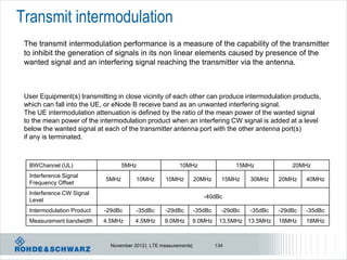
- 25. Adjacent Channel Leakage Ratio - eNB E-UTRA transmitted BS adjacent channel Assumed Filter on the ACLR signal channel centre adjacent adjacent lim bandwidth frequency offset channel channel it BWChannel [MHz] below the first carrier frequency and or above the last (informative) corresponding carrier centre filter bandwidth frequency transmitted 1.4, 3.0, 5, 10, 15, 20 BWChannel E-UTRA of same Square (BWConfig) 45 dB BW 2 x BWChannel E-UTRA of same Square (BWConfig) 45 dB BW BWChannel /2 + 2.5 3.84 Mcps UTRA RRC (3.84 Mcps) 45 dB MHz BWChannel /2 + 7.5 3.84 Mcps UTRA RRC (3.84 Mcps) 45 dB MHz NOTE 1: BWChannel and BWConfig are the channel bandwidth and transmission bandwidth configuration of the E-UTRA transmitted signal on the assigned channel frequency. Large bandwidth NOTE 2: The RRC filter shall be equivalent to the transmit pulse shape filter defined in TS 25.104 [6], with a chip rate as defined in this table. Limit is either -13 / -15dBm absolute or as above November 2012 | LTE measurements| 25
- 26. Adjacent channel leakage power ratio November 2012 | LTE measurements| 26
- 27. ACLR measurement * RBW 10 kHz VBW 30 kHz Ref 0 dBm Att 25 dB SWT 250 ms 0 * A -10 1 AP VIEW -20 2 AP VIEW -30 3 AP CLRWR -40 -50 EXT UTRAACLR1 UTRAACLR2 = 33 dB = 36 dB UTRAACLR2bis 3DB = 43 dB -60 -70 -80 -90 Additional requirement for E-UTRA frequency band I, -100 signaled by network to the UE Center 1.947 GHz 2.5 MHz/ Span 25 MHz fUTRA, ACLR2 fUTRA, ACLR1 fCarrier November 2012 | LTE measurements| 27 Date: 21.AUG.2008 15:51:00
- 28. Operating band unwanted emissions Narrow bandwidth Frequency offset Frequency offset of Minimum requirement Measurem of measurement measurement filter centre ent filter -3dB point, f frequency, f_offset bandwidth (Note 1) 0 MHz f < 5 0.05 MHz f_offset < 5.05 100 kHz 7 f _ offset MHz MHz 7dBm 0.05 dB 5 MHz 5 MHz f < 5.05 MHz f_offset < -14 dBm 100 kHz min(10 MHz, min(10.05 MHz, fmax) f_offsetmax) 10 MHz f 10.05 MHz f_offset < -16 dBm (Note 5) 100 kHz fmax f_offsetmax TS 36.104 defines several limits: depending on Channel bandwidth, additional regional limits and node B limits category A or B for ITU defined regions => Several test setups are possible! November 2012 | LTE measurements| 28
- 29. Operating band unwanted emissions November 2012 | LTE measurements| 29
- 30. Unwanted emissions – spurious emission The transmitter spurious emission limits apply from 9 kHz to 12.75 GHz, excluding the frequency range from 10 MHz below the lowest frequency of the downlink operating band up to 10 MHz above the highest frequency of the downlink operating band Frequency range Maximum level Measurement Note Bandwidth 9kHz - 150kHz 1 kHz Note 1 150kHz - 30MHz 10 kHz Note 1 -13 dBm 30MHz - 1GHz 100 kHz Note 1 1GHz – 12.75 GHz 1 MHz Note 2 NOTE 1: Bandwidth as in ITU-R SM.329 [5] , s4.1 NOTE 2: Bandwidth as in ITU-R SM.329 [5] , s4.1. Upper frequency as in ITU-R SM.329 [5] , s2.5 table 1 Spurious emission limits, Category A November 2012 | LTE measurements| 30
- 31. Spurious emissions – operating band excluded November 2012 | LTE measurements| 31
- 32. Base station maximum power In normal conditions, the base station maximum output power shall remain within +2 dB and -2 dB of the rated output power declared by the manufacturer. Towards External External antenna connector PA device BS e.g. cabinet TX filter (if any) (if any) Test port A Test port B Normal port for Port to be used for measurements measurements in case external equipment is used November 2012 | LTE measurements| 32
- 33. LTE – DVB interference scenarios Adjacent channel leakage of Basestation x into DTT channel N is point of interest For a BS declared to support Band 20 and to operate in geographic areas within the CEPT in which frequencies are allocated to broadcasting (DTT) service, the manufacturer shall additionally declare the following quantities associated with the applicable test conditions of Table 6.6.3.5.3-4 and information in annex G of [TS 36.104] : PEM,N Declared emission level for channel N P10MHz Maximum output Power in 10 MHz November 2012 | LTE measurements| 33
- 34. Base station receiver test Example: Rx test, moving condition 70% of required throughput of FRC, Fixed Reference Channel November 2012 | LTE measurements| 34
- 35. Base station receiver test – HARQ multiplexing UE sends PUSCH with alternating data and data with multiplexed ACK November 2012 | LTE measurements| 35
- 36. Base station test – power dynamics Synchronisation time/frequency BS under Test FFT 2048 Per Symbol 100 subcarrier Detection / RF- CP- RBs, Ampl. decoding correc- remov 1200 /Phase tion sub correction carr EVM Resource element Tx RETP power: Distinguish: •OFDM symbol •Reference symbol November 2012 | LTE measurements| 36
- 37. Downlink Power Reference Signal: Cell-specific PDCCH power PDSCH power to RS, where NO reference referenceSignalPower depending signals are present, is UE specific and (-60…+50dBm), on ρB/ρA signaled by higher layers as PA. signaled in SIB Type 2 For PDSCH power in same [Power] symbol as reference signal an additional cell specific offset is applied, that is signaled by -50.00 dBm higher layers as PB. PA = -4.77 dB 2011 © Rohde&Schwarz -54.77 dBm PB = 3 (-3.98 dB) -58.75 dBm 0 1 2 3 4 5 6 7 8 9 10 11 12 13 [Time] OFDM symbols RS EPRE = Reference Signal Reference signal power = linear average of all Ref. Energy per Resource Element Symbols over whole channel bandwidth EPRE PDSCH A / B EPRE RS B PB A A PA (with some exeptions for MIMO) November 2012 | LTE measurements| 37
- 38. Base station test – output power dynamics Measure avg OFDM symbol power + Compare active and non-active case Ref. Symbol, always on OFDM Symbol not active! OFDM Symbol active! PDSCH # of 64QAM PDSCH PRBs within a slot for which EVM is measured 1 1 1 1 1 1 Test model: PRB PA = EA/ERS [dB] 0 0 0 0 0 0 E-TM3.1 # of PDSCH PRBs which are not allocated 5 14 24 49 74 99 All RB allocated Test model: PDSCH # of 64QAM PDSCH PRBs within a slot for which EVM 6 15 25 50 75 100 E-TM2 is measured Only 1 RB allocated November 2012 | LTE measurements| 38
- 39. DL Modulation quality: Constellation diagram LTE downlink: several channels can be seen (example): PDSCH with 16 QAM PDCCH + PBCH with QPSK S-SCH with BPSK CAZAC Sequences, Reference signals November 2012 | LTE measurements| 39
- 40. LTE RF measurements on user equipment UEs November 2012 | LTE measurements| 40
- 41. LTE Transmitter Measurements 1 Transmit power 1.1 UE Maximum Output Power 1.2 Maximum Power Reduction (MPR) 1.3 Additional Maximum Power Reduction (A-MPR) 1.4 Configured UE transmitted Output Power 2 Output Power Dynamics 2.1 Minimum Output Power 2.2 Transmit OFF power 2.3 ON/OFF time mask 2.3.1 General ON/OFF time mask 2.3.2 PRACH time mask 2.3.3 SRS time mask 2.4 Power Control 2.4.1 Power Control Absolute power tolerance 2.4.2 Power Control Relative power tolerance 2.4.3 Aggregate power control tolerance 3 Transmit signal quality 3.1 Frequency Error 3.2 Transmit modulation 3.2.1 Error Vector Magnitude (EVM) 3.2.2 Carrier leakage 3.2.3 In-band emissions for non allocated RB 3.2.4 EVM equalizer spectrum flatness 4 Output RF spectrum emissions 4.1 Occupied bandwidth 4.2 Out of band emission 4.2.1 Spectrum Emission Mask 4.2.2 Additional Spectrum Emission Mask 4.2.3 Adjacent Channel Leakage power Ratio 4.3 Spurious emissions 4.3.1 Transmitter Spurious emissions 4.3.2 Spurious emission band UE co-existence 4.3.3 Additional spurious emissions 5 Transmit intermodulation November 2012 | LTE measurements| 41
- 42. UE Signal quality – symbolic structure of mobile radio tester MRT Test equipment Rx TxRx EVM … … … equalizer IDFT meas. DUT RF correction FFT Inband- … … … emmissions l Carrier Frequency error l EVM (Error Vector Magnitude) l Origin offset + IQ offset l Unwanted emissions, falling into non allocated resource blocks. l Inband transmission l Spectrum flatness November 2012 | LTE measurements| 42
- 43. UL Power Control: Overview UL-Power Control is a combination of: l Open-loop: UE estimates the DL-Path- loss and compensates it for the UL l Closed-loop: in addition, the eNB controls directly the UL- Power through power- control commands transmitted on the DL November 2012 | LTE measurements| 43
- 44. PUSCH power control l Power level [dBm] of PUSCH is calculated every subframe i based on the following formula out of TS 36.213 MPR Maximum allowed UE power in this particular cell, Combination of cell- and UE-specific PUSCH transport but at maximum +23 dBm1) components configured by L3 format Number of allocated Cell-specific Downlink Power control resource blocks (RB) parameter path loss adjustment derived Transmit power for PUSCH configured by L3 estimate from TPC command in subframe i in dBm received in subframe (i-4) Bandwidth factor Basic open-loop starting point Dynamic offset (closed loop) 1) +23 dBm is maximum allowed power in LTE according to TS 36.101, corresponding to power class 3bis in WCDMA November 2012 | LTE measurements| 44
- 45. Pcmax definition „upper“ tolerance „lower“ tolerance „corrected“ UE power PCMAX_L– T(PCMAX_L) ≤ PCMAX ≤ PCMAX_H + T(PCMAX_H) PCMAX_L = min{PEMAX_L, PUMAX } PCMAX_H = min{PEMAX_H, PPowerClass} Max. power permitted Max. power in cell, permitted in cell considering bandwidth confinement Max. power for UE Max. power for UE, considering maximum power reduction November 2012 | LTE measurements| 45
- 46. Pcmax definition PCMAX_L– T(PCMAX_L) ≤ PCMAX ≤ PCMAX_H + T(PCMAX_H), lPCMAX_L = min{PEMAX_L , PUMAX }, l PEMAX_L is the maximum allowed power for this particular radio cell configured by higher layers and corresponds to P-MAX information element (IE) provided in SIB Type1 l l PEMAX_L is reduced by 1.5 dB when the transmission BW is confined within FUL_low and FUL_low+4 MHz or FUL_high – 4 MHz and FUL_high, PPowerClass + 2dB 23dBm PPowerClass - 2dB -1.5dB -1.5dB FUL_low FUL_high- 4MHz FUL_high November 2012 | LTE measurements| 46
- 47. Pcmax definition PCMAX_L– T(PCMAX_L) ≤ PCMAX ≤ PCMAX_H + T(PCMAX_H), PCMAX_L = min{PEMAX_L , PUMAX }, l PUMAX corresponds to maximum power (depending on power class, taking into account Maximum Power Reduction MPR and additional A-MPR UE may decide to reduce power UE power class Network may signal = 23dBm ±2 dB bandwidth restriction NS_0x November 2012 | LTE measurements| 47
- 48. UE Maximum Power Reduction UE transmits at maximum power, maximum allowed TX power reduction is given as Modulation Channel bandwidth / Transmission bandwidth configuration MPR (dB) [RB] 1.4 3.0 5 10 15 20 MHz MHz MHz MHz MHz MHz QPSK >5 >4 >8 > 12 > 16 > 18 ≤1 16 QAM ≤5 ≤4 ≤8 ≤ 12 ≤ 16 ≤ 18 ≤1 16 QAM Full >5 >4 >8 > 12 > 16 > 18 ≤2 Higher order modulation schemes require more dynamic -> UE will slightly repeal its confinement for maximum power November 2012 | LTE measurements| 48
- 49. UE Additional Maximum Power Reduction A-MPR Additional maximum Network Requirements E-UTRA Band Channel Resource A-MPR (dB) Signaling (sub-clause) Bandwidth Blocks power reduction value (MHz) requirements can be NS_01 NA NA NA NA NA signaled by the 6.6.2.2.3.1 2,4,35,36 3 >5 ≤1 network as NS value 6.6.2.2.3.1 2,4,10,35,36 5 >6 ≤1 in SIB2 NS_03 6.6.2.2.3.1 2,4,10,35,36 10 >6 ≤1 (IE AdditionalSpectrumEmission) 6.6.2.2.3.1 2,4,10,35,36 15 >8 ≤1 6.6.2.2.3.1 2,4,10,35,36 20 >10 ≤1 NS_04 6.6.2.2.3.2 TBD TBD TBD TBD NS_05 6.6.3.3.3.1 1 10,15,20 ≥ 50 for QPSK ≤1 NS_06 6.6.2.2.3.3 12, 13, 14, 17 1.4, 3, 5, 10 n/a n/a 6.6.2.2.3.3 Table NS_07 13 10 Table 6.2.4.3-2 6.6.3.3.3.2 6.2.4.3-2 > 29 ≤1 NS_08 6.6.3.3.3.3 19 10, 15 > 39 ≤2 > 44 ≤3 [NS_09] 6.6.3.3.3.4 21 TBD TBD TBD .. NS_32 - - - - - November 2012 | LTE measurements| 49
- 50. PUSCH power control Transmit output power ( PUMAX), cont’d. 3GPP Band 13 746 756 777 787 DL UL Network Requiremen Channel E-UTRA Resources A-MPR Signalling ts bandwidth Band Blocks (dB) Value (sub-clause) (MHz) … … … … … … Table Table 6.6.2.2.3 NS_07 13 10 6.2.4 6.2.4 6.6.3.3.2 -2 -2 Indicates the lowest RB … … … … … … index of transmitted Region A Region B Region C resource blocks RBStart 0 – 12 13 – 18 19 – 42 43 – 49 Defines the length of a contiguous RB allocation LCRB [RBs] 6–8 1 – 5 to 9 – 50 ≥8 ≥18 ≤2 A-MPR [dB] 8 12 12 6 3 l In case of EUTRA Band 13 depending on RB allocation as well as number of contiguously allocated RB different A-MPR needs to be considered. November 2012 | LTE measurements| 50
- 51. Pcmax definition – tolerance values PCMAX_L– T(PCMAX_L) ≤ PCMAX ≤ PCMAX_H + T(PCMAX_H) PCMAx Tolerance (dBm) T(PCMAX) (dB) 21 ≤ PCMAX ≤ 23 2.0 Tolerance is 20 ≤ PCMAX < 21 2.5 depending on 19 ≤ PCMAX < 20 3.5 power levels 18 ≤ PCMAX < 19 4.0 13 ≤ PCMAX < 18 5.0 8 ≤ PCMAX < 13 6.0 -40 ≤ PCMAX < 8 7.0 November 2012 | LTE measurements| 51
- 52. Pcmax definition – tolerance values PCMAX_L– T(PCMAX_L) ≤ PCMAX ≤ PCMAX_H + T(PCMAX_H) PCMAX_H = min{PEMAX_H , PPowerClass }, l PEMAX_H is the maximum allowed power for this particular radio cell configured by higher layers and corresponds to P-MAX information element (IE) provided in SIB Type 1 UE power class = 23dBm ±2 dB November 2012 | LTE measurements| 52
- 53. Pcmax definition – tolerance values PCMAX_L– T(PCMAX_L) ≤ PCMAX ≤ PCMAX_H + T(PCMAX_H) PCMAX_H = min{PEMAX_H , PPowerClass }, l PPowerClass. There is just one power class specified for LTE, corresponding to power class 3bis in WCDMA with +23 dBm ± 2dB, MPR and A-MPR are not taken into account, Class 1 Tolerance Class 2 Tolerance Class 3 Tolerance (dB) Class 4 Tolerance (dB) EUTRA (dB (dB) (dBm) (dB) (dBm (dBm) band m) ) 1 23 ±2 2 23 ±22 … 23 ±22 40 23 ±2 November 2012 | LTE measurements| 53
- 54. Pcmax value for power control - analogies PCMAX_L– T(PCMAX_L) ≤ PCMAX ≤ PCMAX_H + T(PCMAX_H) PCMAX_L = min{PEMAX_L, PUMAX } PCMAX_H = min{PEMAX_H, PPowerClass} Maximum speed = 280 km/h =PPowerClass Under those conditions, I shall drive more carefully! Not going to the max seed! =PEMAX_H =PEMAX_L =PUMAX -> speed reduction November 2012 | LTE measurements| 54
- 55. LTE RF Testing: UE Maximum Power UE transmits with 23dBm ±2 dB QPSK modulation is used. All channel bandwidths are tested separately. Max power is for all band classes Test is performed for varios uplink allocations November 2012 | LTE measurements| 55
- 56. Resource Blocks number and maximum RF power 1 active resource block (RB), Nominal RF power band width One active resource block 10 MHz = 50 RB’s (RB) provides maximum absolute RF power Frequency More RB’s in use will be at RF power lower RF power in order to create same integrated power Frequency RF power Additionally, MPR (Max. Power Reduction) and A- MPR MPR are defined Frequency November 2012 | LTE measurements| 56
- 57. UE Maximum Output Power – Test Configuration Initial Conditions Test Environment as specified in TS 36.508 subclause 4.1 Normal, TL/VL, TL/VH, TH/VL, TH/VH Temperature/Voltage Test Frequencies as specified in TS 36.508 subclause 4.3.1 Low range, Mid range, High range high/low Test Channel Bandwidths as specified in TS 36.508 subclause 4.3.1 Lowest, 5MHz, Highest Test Parameters for Channel Bandwidths Downlink Configuration Uplink Configuration Ch BW N/A for Max UE output power testing Mod’n RB allocation FDD TDD 1.4MHz QPSK 1 1 1.4MHz QPSK 5 5 3MHz QPSK 1 1 3MHz QPSK 4 4 5MHz QPSK 1 1 5MHz QPSK 8 8 10MHz QPSK 1 1 10MHz QPSK 12 12 15MHz QPSK 1 1 15MHz QPSK 16 16 20MHz QPSK 1 1 20MHz QPSK 18 18 November 2012 | LTE measurements| 57
- 58. UE maximum power PPowerClass + 2dB 23dBm PPowerClass - 2dB maximum output FUL_high FUL_low power for any transmission bandwidth within the channel bandwidth November 2012 | LTE measurements| 58
- 59. UE maximum power – careful at band edge! PPowerClass + 2dB 23dBm PPowerClass - 2dB -1.5dB -1.5dB FUL_low FUL_high- 4MHz FUL_high FUL_low+4MHz For transmission bandwidths confined within FUL_low and FUL_low + 4 MHz or FUL_high – 4 MHz and FUL_high, the maximum output power requirement is relaxed by reducing the lower tolerance limit by 1.5 dB November 2012 | LTE measurements| 59
- 60. UE maximum power - examples Example 1: No maximum power reduction by higher layers PCMAX_L– T(PCMAX_L) ≤ PCMAX ≤ PCMAX_H + T(PCMAX_H) PCMAX_L = min{PEMAX_L, PUMAX } PCMAX_H = min{PEMAX_H, PPowerClass} Max. power permitted in cell, Max. power for UE, Max. power permitted in Max. power for UE considering bandwidth considering maximum power cell confinement reduction PEMAX_L = none PUMAX = power class 3 = +23 dBm T(PCMAX_L) = T(PCMAX_H)=2dB PEMAX_H = none PPowerClass = power class 3 = +23 dBm PPowerClass + 2dB 25dBm 23dBm PPowerClass - 2dB 21dBm FUL_low FUL_high November 2012 | LTE measurements| 60
- 61. UE maximum power - examples Example 2: max cell power = 0 dBm + band edge maximum power reduction PCMAX_L– T(PCMAX_L) ≤ PCMAX ≤ PCMAX_H + T(PCMAX_H) PCMAX_L = min{PEMAX_L, PUMAX } PCMAX_H = min{PEMAX_H, PPowerClass} PEMAX_L = 0dBm -1.5 dB relaxation = -1.5dBm PEMAX_H = 0 dBm PUMAX = power class 3 – band relaxation = +21.5 dBm PPowerClass = power class 3 = +23 dBm PCMAX_L=-1.5dBm PCMAX_H=0 dBm T(PCMAX_L) = T(PCMAX_H)=7dB PCMAX_H + 7dB +7dBm 0 dBm PCMAX_L - 7dB -8.5dBm FUL_low FUL_low+4MHz FUL_high November 2012 | LTE measurements| 61
- 62. UE maximum power - examples Example 3: Band 13 with NS_07 signalled ( = A-MPR). No Max Power restriction 16 QAM, 12 Resource blocks and RB start = 13. Bandwidth = 10 MHz MPR = 1dB, A-MPR = 12 dB, no band edge relaxation PCMAX_L– T(PCMAX_L) ≤ PCMAX ≤ PCMAX_H + T(PCMAX_H) PCMAX_H = min{PEMAX_H, PPowerClass} PCMAX_L = min{PEMAX_L, PUMAX } PEMAX_L = none PEMAX_H = none PUMAX = power class 3 – MPR – A.MPR = +10 dBm PPowerClass = power class 3 = +23 dBm PCMAX_L=10 dBm T(PCMAX_L) = 6 dB PCMAX_H=23 dBm +25dBm T(PCMAX_H)=2dB PCMAX_H +2dB 23 dBm PCMAX_L - 6dB 4 dBm RB start = 13 12 Resource blocks FUL_high November 2012 | LTE measurements| 62
- 63. UE maximum power - examples Example 4: band edge power relaxation – no higher layer reduction signalled QPSK, 15 RBs allocated, Band 2, RB allocated at band edge MPR = 1dB, A-MPR = 1 dB, band edge relaxation of 1.5dB PCMAX_L– T(PCMAX_L) ≤ PCMAX ≤ PCMAX_H + T(PCMAX_H) PCMAX_L = min{PEMAX_L, PUMAX } PCMAX_H = min{PEMAX_H, PPowerClass} PEMAX_L =none PEMAX_H = none PUMAX = power class 3 – MPR-A-MPR-band relaxation PPowerClass = power class 3 = +23 dBm = 23-1-1-1.5=+19.5 dBm PCMAX_H= 23 dBm PCMAX_L=19.5dBm PCMAX_H + 2dB +25 dBm T(PCMAX_L) = 3.5 dB T(PCMAX_H)=2dB 23 dBm PCMAX_L – 2 dB PCMAX_L – 3.5 dB +16 dBm FUL_low FUL_low+4MHz FUL_high November 2012 | LTE measurements| 63
- 64. LTE RF Testing: UE Minimum Power UE transmits with -40dBm All channel bandwidths are tested separately. Minimum power is for all band classes < -39 dBm November 2012 | LTE measurements| 64
- 65. LTE RF Testing: UE Off Power The transmit OFF power is defined as the mean power in a duration of at least one sub-frame (1ms) excluding any transient periods. The transmit OFF power shall not exceed the values specified in table below Channel bandwidth / Minimum output power / measurement bandwidth 1.4 3.0 5 10 15 20 MHz MHz MHz MHz MHz MHz Transmit OFF power -50 dBm Measurement 1.08 MHz 2.7 MHz 4.5 MHz 9.0 MHz 13.5 MHz 18 MHz bandwidth November 2012 | LTE measurements| 65
- 66. Power Control Related test items l Absolute Power Control Tolerance -- PUSCH open loop power control l Relative Power Control Tolerance – PUSCH relative power control, including both power ramping and power change due to Ressource block allocation change or TPC commands l Aggregate Power Control – PUSCH and PUCCH power control ability when RB changes every subframe November 2012 | LTE measurements| 66
- 67. Absolute Power Control Tolerance l The purpose of this test is to verify the UE transmitter’s ability to set its initial output power to a specific value at the start of a contiguous transmission or non-contiguous transmission with a long transmission gap. November 2012 | LTE measurements| 67
- 68. Power Control - Absolute Power Tolerance l …. ability to set initial output power to a specific value at the start of a contiguous transmission or non-contiguous transmission with a long transmission gap (>20ms). l Set p0-NominalPUSCH to -105 (test point 1) and -93 (test point 2) l Test requirement example for test point 1: Channel bandwidth / expected output power (dBm) 1.4 3.0 5 10 15 20 MHz MHz MHz MHz MHz MHz Expected Measured -14.8 ± -10.8 ± -8.6 ± -5.6 ± -3.9 ± -2.6 ± power Normal 10.0 10.0 10.0 10.0 10.0 10.0 conditions Expected Measured -14.8 ± -10.8 ± -8.6 ± -5.6 ± -3.9 ± -2.6 ± power Extreme 13.0 13.0 13.0 13.0 13.0 13.0 conditions November 2012 | LTE measurements| 68
- 69. Configured UE transmitted Output Power IE P-Max (SIB1) = PEMAX To verify that UE follows rules sent via system information, SIB Test: set P-Max to -10, 10 and 15 dBm, measure PCMAX Channel bandwidth / maximum output power 1.4 3.0 5 10 15 20 MHz MHz MHz MHz MHz MHz PCMAX test point 1 -10 dBm ± 7.7 PCMAX test point 2 10 dBm ± 6.7 PCMAX test point 3 15 dBm ± 5.7 November 2012 | LTE measurements| 69
- 70. LTE Power versus time RB allocation is main source for power change Not scheduled Resource block PPUSCH (i) min{PMAX ,10 log10 (M PUSCH (i)) PO_PUSCH ( j ) PL TF (TF (i)) f (i)} Bandwidth allocation Given by higher layers TPC commands or not used November 2012 | LTE measurements| 70
- 71. Accumulative TPC commands TPC Command Field Accumulated In DCI format 0/3 PUSCH [dB] 0 -1 1 0 2 1 3 3 2 minimum power in LTE November 2012 | LTE measurements| 71
- 72. Absolute TPC commands PPUSCH (i) min{ PMAX ,10 log 10 ( M PUSCH (i)) PO_PUSCH ( j ) PL TF (TF (i)) f (i)} TPC Command Field Absolute PUSCH [dB] In DCI format 0/3 only DCI format 0 0 -4 1 -1 2 1 3 4 Pm -1 -4 November 2012 | LTE measurements| 72
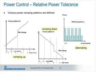
- 73. Relative Power Control Power pattern B Power pattern A RB change RB change 0 .. 9 sub-frame# 0 .. 9 sub-frame# 1 2 3 4 radio frame 1 2 3 4 radio frame Power pattern C l The purpose of this test is to verify RB change the ability of the UE transmitter to set its output power relatively to the power in a target sub-frame, relatively to the power of the most recently transmitted reference sub-frame, if the 0 .. 1 9 sub-frame# 2 3 4 radio frame transmission gap between these sub- frames is ≤ 20 ms. November 2012 | LTE measurements| 73
- 74. Power Control – Relative Power Tolerance l …. ability to set output power relative to the power in a target sub frame, relative to the power of the most recently transmitted reference sub-frame, if the transmission gap between these sub-frames is ≤ 20 ms. November 2012 | LTE measurements| 74
- 75. Power Control – Relative Power Tolerance l Various power ramping patterns are defined ramping down alternating ramping up November 2012 | LTE measurements| 75
- 76. UE power measurements – relative power change All combinations of All combinations of PUSCH/PUCCH Power step P PUSCH and and SRS (Up or down) PRACH [dB] PUCCH transitions [dB] transitions [dB] between sub- frames [dB] ΔP < 2 ±2.5 (Note 3) ±3.0 ±2.5 2 ≤ ΔP < 3 ±3.0 ±4.0 ±3.0 3 ≤ ΔP < 4 ±3.5 ±5.0 ±3.5 4 ≤ ΔP ≤ 10 ±4.0 ±6.0 ±4.0 10 ≤ ΔP < 15 ±5.0 ±8.0 ±5.0 15 ≤ ΔP ±6.0 ±9.0 ±6.0 P Power tolerance relative given by table time November 2012 | LTE measurements| 76
- 77. UE power measurements – relative power change Power Power FDD test patterns TDD test patterns test for each bandwidth, here 10MHz 0 1 9 sub-frame# 0 2 3 7 8 9 sub-frame# Sub-test Uplink RB allocation TPC command Expected power Power step size step size range (Up or PUSCH/ (Up or down) down) ΔP [dB] ΔP [dB] [dB] A Fixed = 25 Alternating TPC = 1 ΔP < 2 1 ± (1.7) +/-1dB B Alternating 10 and 18 TPC=0dB 2.55 2 ≤ ΔP < 3 2.55 ± (3.7) C Alternating 10 and 24 TPC=0dB 3.80 3 ≤ ΔP < 4 3.80 ± (42.) D Alternating 2 and 8 TPC=0dB 6.02 4 ≤ ΔP < 10 6.02 ± (4.7) E Alternating 1 and 25 TPC=0dB 13.98 10 ≤ ΔP < 15 13.98 ± (5.7) F Alternating 1 and 50 TPC=0dB 16.99 15 ≤ ΔP 16.99 ± (6.7) November 2012 | LTE measurements| 77
- 78. UE aggregate power tolerance Aggregate power control tolerance is the ability of a UE to maintain its power in non-contiguous transmission within 21 ms in response to 0 dB TPC commands TPC command UL channel Aggregate power tolerance within 21 ms 0 dB PUCCH ±2.5 dB 0 dB PUSCH ±3.5 dB Note: 1. The UE transmission gap is 4 ms. TPC command is transmitted via PDCCH 4 subframes preceding each PUCCH/PUSCH transmission. Tolerated UE power P deviation UE power with TPC = 0 Time = 21 milliseconds November 2012 | LTE measurements| 78
- 79. Aggregate Power Control l The purpose of this test is to verify the UE’s ability to maintain its power level during a non-contiguous transmission within 21 ms in response to 0 dB TPC commands with respect to the first UE transmission, when the power control parameters specified in TS 36.213 are constant. l Both PUSCH mode and PUCCH mode need to be tested Power Power FDD test patterns TDD test patterns 0 5 0 5 0 3 8 3 8 3 sub-frame# sub-frame# November 2012 | LTE measurements| 79
- 80. UE aggregate power tolerance Power Power FDD test patterns TDD test patterns 0 5 0 5 0 3 8 3 8 3 sub-frame# sub-frame# Test performed with scheduling gap of 4 subframes November 2012 | LTE measurements| 80
- 81. UE power measurement – timing masks Start Sub-frame End sub-frame Start of ON power End of ON power End of OFF power Start of OFF power requirement requirement * The OFF power requirements does not apply for DTX and measurement gaps 20µs 20µs Transient period Transient period Timing definition OFF – ON commands Timing definition ON – OFF commands November 2012 | LTE measurements| 81
- 82. Power dynamics PUSCH = OFF PUSCH = ON PUSCH = OFF time Please note: scheduling cadence for power dynamics November 2012 | LTE measurements| 82
- 83. General ON/OFF time mask Measured subframe = 2 UL/DL Scheduling should be configured properly. TDD Issues: - Special Subframe Configuration - >off power before is highter than off power after - <> tune down DL power November 2012 | LTE measurements| 83
- 84. PRACH time mask PRACH ON power requirement End of OFF power Start of OFF power requirement requirement 20µs 20µs Transient period Transient period PRACH Channel bandwidth / Output Power [dBm] / measurement Measurement bandwidth preamble period (ms) format 1.4 3.0 5 10 15 20 0 0.9031 MHz MHz MHz MHz MHz MHz Transmit OFF 1 1.4844 -48.5 dBm power 2 1.8031 Transmission OFF 3 2.2844 Measurement 1.08 MHz 2.7 MHz 4.5 MHz 9.0 MHz 13.5 MHz 18 MHz bandwidth 4 0.1479 Expected PRACH Transmission ON -1± 7.5 -1 ± 7.5 -1 ± 7.5 -1 ± 7.5 -1 ± 7.5 -1 ± 7.5 Measured power November 2012 | LTE measurements| 84
- 85. UE power measurement – PRACH timing mask PRACH preamble format Measurement period (ms) 0 0.9031 1 1.4844 2 1.8031 3 2.2844 4 0.1479 PRACH ON power requirement End of OFF power Start of OFF power requirement requirement 20µs 20µs Transient period Transient period November 2012 | LTE measurements| 85
- 86. PRACH measurements For PRACH you have to set a trigger Reminder: PRACH is CAZAC sequence November 2012 | LTE measurements| 86
- 87. PRACH measurement: constellation diagram Reminder: PRACH is CAZAC sequence November 2012 | LTE measurements| 87
- 88. PRACH measurement: power dynamics November 2012 | LTE measurements| 88
- 89. Sounding Reference Signal Time Mask November 2012 | LTE measurements| 89
- 90. UE power measurement – SRS timing mask SRS SRS ON power requirement Single Sounding Reference Symbol End of OFF Start of OFF power power requirement requirement 20µs 20µs Transient period Transient period SRS SRS Double Sounding SRS ON power SRS ON power Reference Symbol requirement requirement End of OFF Start of OFF power power requirement requirement 20µs 20µs 20µs 20µs Transient period *Transient period Transient period * Transient period is only specifed in the case of frequency hopping or a power change between SRS symbols November 2012 | LTE measurements| 90
- 91. UE power measurement – Subframe / slot boundary N+1 Sub-frame N0 Sub-frame N+2 Sub-frame Sloti Sloti+1 Start of N+1 power End of N+1 power requirement requirement 20µs 20µs 20µs 20µs 20µs 20µs Transient period Transient period Transient period If intra-slot hopping is enabled Periods where power changes may occur November 2012 | LTE measurements| 91
- 92. Tx power aspects RB power = Ressource Block Power, power of 1 RB TX power = integrated power of all assigned RBs November 2012 | LTE measurements| 92
- 93. Resource allocation versus time PUCCH allocation No resource scheduled PUSCH allocation, different #RB and RB offset November 2012 | LTE measurements| 93
- 94. TTI based scheduling November 2012 | LTE measurements| 94
- 95. LTE scheduling impact on power versus time TTI based scheduling. Different RB allocation Impact on UE power November 2012 | LTE measurements| 95
- 96. Transmit signal quality November 2012 | LTE measurements| 96
- 97. Transmit signal quality – carrier leakage Frequency error fc Fc+ε f Carrier leakage (The IQ origin offset) is an additive sinusoid waveform that has the same frequency as the modulated waveform carrier frequency. Parameters Relative Limit (dBc) Output power >0 dBm -25 -30 dBm ≤ Output power ≤0 dBm -20 -40 dBm Output power < -30 dBm -10 November 2012 | LTE measurements| 97
- 98. Frequency Error …. ability of both the receiver and the transmitter to process frequencies correctly… The 20 frequency error Δf results must fulfil this test requirement: |Δf| ≤ (0.1 PPM + 15 Hz) observed over a period of one time slot (0.5ms) November 2012 | LTE measurements| 98
- 99. Impact on Tx modulation accuracy evaluation l 3 modulation accuracy requirements l EVM for the allocated RBs l LO leakage for the centred RBs ! LO spread on all RBs l I/Q imbalance in the image RBs LO leakage level RF carrier signal I/Q imbalance noise RB0 RB1 RB2 RB3 RB4 RB5 frequency EVM November 2012 | LTE measurements| 99
- 100. Inband emissions 3 types of inband emissions: general, DC and IQ image Used allocation < ½ channel bandwidth channel bandwidth November 2012 | LTE measurements| 100
- 101. Carrier Leakage Carrier leakage (the I/Q origin offset) is a form of interference caused by crosstalk or DC offset. It expresses itself as an un-modulated sine wave with the carrier frequency. I/Q origin offset interferes with the center sub carriers of the UE under test. The purpose of this test is to evaluate the UE transmitter to verify its modulation quality in terms of carrier leakage. DC carrier leakage due to IQ offset LO Parameters Relative Leakage Limit (dBc) Output power >0 dBm -25 -30 dBm ≤ Output power ≤0 dBm -20 -40 dBm Output power < -30 dBm -10 November 2012 | LTE measurements| 101
- 102. Inband emmission – error cases DC carrier leakage due to IQ offset November 2012 | LTE measurements| 102
- 103. Inband emmission – error cases Inband image due to IQ inbalance November 2012 | LTE measurements| 103
- 104. Inband emmission – error cases Inband image due to IQ inbalance November 2012 | LTE measurements| 104
- 105. DC leakage and IQ imbalance in real world … November 2012 | LTE measurements| 105
- 106. UL Modulation quality: Constellation diagram LTE PUSCH uses QPSK, 16QAM and 64 QAM (optional) modulation schemes. In UL there is only 1 scheme allowed per subframe November 2012 | LTE measurements| 106
- 107. Error Vector Magnitude, EVM Q Magnitude Error (IQ error magnitude) Error Vector Measured Signal Ideal (Reference) Signal Φ Phase Error (IQ error phase) I Reference Waveform 011001… Ideal Demodulator Modulator - Input Signal Σ Difference Signal + Measured Waveform November 2012 | LTE measurements| 107
- 108. Error Vector Magnitude, EVM 7 symbols / slot 0123456 0123456 0123456 0123456 time PUSCH symbol frequency Demodulation Reference symbol, DMRS Limit values Unit Level Parameter QPSK % 17.5 16QAM % 12.5 64QAM % [tbd] November 2012 | LTE measurements| 108
- 109. Error Vector Magnitude, EVM CP center 1 SC-FDMA symbol, including Cyclic Prefix, CP OFDM Cyclic Symbol prefix Part equal to CP FFT Window size FFT window size depends on channel bandwidth and extended/normal CP length November 2012 | LTE measurements| 109
- 110. Error Vector Magnitude, EVM CP center 1 SC-FDMA symbol, including Cyclic Prefix, CP OFDM Cyclic Symbol prefix Part equal to CP FFT Window size FFT window size depends on channel bandwidth and extended/normal CP length Cyclic prefix length N cp Ratio of N cp Cyclic prefix EVM Channel W to CP for symbols 1 Nominal for symbols window Bandwidt for symbol 0 for to 6 FFT size 1 to 6 in FFT length h MHz symbols 1 samples W to 6* FFT window does 1.4 128 9 [5] [55.6] 3 256 18 [12] [66.7] not capture the 5 512 36 [32] [88.9] full length: OFDM 10 160 144 1024 72 [66] [91.7] Symbol + CP 15 1536 108 [102] [94.4] 20 2048 144 [136] [94.4] * Note: These percentages are informative and apply to symbols 1 through 6. Symbol 0 has a longer CP and therefore a lower percentage. Table from TS 36.101 for normal CP November 2012 | LTE measurements| 110
- 111. EVM measurement according to Spec Test Parameters for Channel Bandwidths Downlink Uplink Configuration l Applies to PUSCH, PUCCH Configuration Ch BW N/A for PUSCH EVM Mod’n RB allocation and PRACH 1.4MHz testing QPSK FDD 6 TDD 6 l PUSCH and PUCCH UL Tx 1.4MHz 1.4MHz QPSK 16QAM 1 6 1 6 1.4MHz 16QAM 1 1 Pwer 3MHz QPSK 15 15 l @ Max & -36.8 dBm 3MHz QPSK 4 4 3MHz 16QAM 15 15 3MHz 16QAM 4 4 l PRACH UL Tx Power 5MHz QPSK 25 25 5MHz QPSK 8 8 l FDD: @ -31 dBm & 14 dBm* 5MHz 5MHz 16QAM 16QAM 25 8 25 8 l TDD: @ -39 dBm & 6 dBm 10MHz 10MHz QPSK QPSK 50 12 50 12 10MHz 16QAM 50 50 (Note 3) (Note 3) 10MHz 16QAM 12 12 15MHz QPSK 75 75 15MHz QPSK 16 16 15MHz 16QAM 75 75 (Note 3) (Note 3) 15MHz 16QAM 16 16 20MHz QPSK 100 100 20MHz QPSK 18 18 20MHz 16QAM 100 100 (Note 3) (Note 3) 20MHz 16QAM 18 18 Note 1: Test Channel Bandwidths are checked separately for each E- * 20MHz, we can only reach 13 dBm UTRA band, which applicable channel bandwidths are specified in Table 5.4.2.1-1. Note 2: For partial RB allocation, the starting resource block shall be RB #0 and RB# (max+1 - RB allocation) of the channel bandwidth. November 2012 | LTE measurements| Note 3: 111 Applies only for UE-Categories 2-5
- 112. Cyclic prefix aspects We can observe a phase shift CP CP CP part CP part OFDM symbol n-1 OFDM symbol n Content is OFDM symbol is periodic! different in each OFDM symbol Cyclic prefix does not provoque phase shift November 2012 | LTE measurements| 112
- 113. Time windowing 1 SC-FDMA symbol, including Cyclic Prefix, CP 1 SC-FDMA symbol, including Cyclic Prefix, CP OFDM OFDM Cyclic Symbol Cyclic Symbol prefix Part equal prefix Part equal to CP to CP Continuous phase shift Difference in phase shift Phase shift between SC-FDMA symbols will cause side lobes in spectrum display! November 2012 | LTE measurements| 113
- 114. Time windowing Tx time window creates some kind of clipping in symbol transitions Tx Time window Tx Time window OFDM OFDM Cyclic Symbol Cyclic Symbol prefix Part equal prefix Part equal to CP to CP Continuous phase shift Difference in phase shift Tx time window can be used to shape the Tx spectrum in a more steep way, but …. November 2012 | LTE measurements| 114
- 115. Time windowing Tx time window creates some kind of clipping in symbol transitions Tx Time window Tx Time window OFDM OFDM Cyclic Symbol Cyclic Symbol prefix Part equal prefix Part equal to CP to CP Continuous phase shift Difference in phase shift Tx time window will create a higher Error Vector Magnitude! Here the Tx time window of 5µsec causes Some mismatch between the 2 EVM Measurements of the first SC-FDMA symbol November 2012 | LTE measurements| 115
- 116. EVM vs. subcarrier Nominal subcarriers Each subcarrier Modulated with e.g. QPSK Integration of all f Error Vectors to Display EVM curve f0 f1 f2 f3 Error vector .... Error vector Note: simplified figure: in reality you compare the waveforms due to SC-FDMA November 2012 | LTE measurements| 116
- 117. EVM vs. subcarrier November 2012 | LTE measurements| 117
- 118. EVM Equalizer Spectrum Flatness The EVM equalizer spectrum flatness is defined as the variation in dB of the equalizer coefficients generated by the EVM measurement process. The EVM equalizer spectrum flatness requirement does not limit the correction applied to the signal in the EVM measurement process but for the EVM result to be valid, the equalizer correction that was applied must meet the EVM equalizer spectral flatness minimum requirements. Nominal subcarriers Amplitude Equalizer coefficients f f0 f1 f2 f3 Subcarriers before equalization Integration of all 1 amplitude equalizer coefficients to display | A( EC ( f )) |2 12 * N RB 12* N RB P( f ) 10 * log spectral flatness curve | A( EC ( f ) |2 November 2012 | LTE measurements| 118
- 119. Equalization 1-tap equalization = Interpreting the frequency Selectivity as scalar factor Equalizer tries to set same power level for all subcarriers A(f) 1-tap equalization = Calculating scalar to amplify or attenuate f November 2012 | LTE measurements| 119
- 120. Spectrum flatness calculation 1-tap equalization = Interpreting the frequency Equalizer tries to Selectivity as scalar factor set same power level for all subcarriers A(f) 1 1-tap equalization = | A( EC ( f )) |2 12 * N RB 12* N RB Calculating scalar to P( f ) 10 * log amplify or attenuate | A( EC ( f ) |2 f November 2012 | LTE measurements| 120
- 121. Spectral flatness November 2012 | LTE measurements| 121
- 122. Spectrum Flatness Maximum Ripple [dB] Frequency Range FUL_Meas – FUL_Low ≥ 3 MHz and FUL_High – FUL_Meas ≥ 3 MHz 5.4 (p-p) (Range 1) FUL_Meas – FUL_Low < 3 MHz or FUL_High – FUL_Meas < 3 MHz 9.4 (p-p) (Range 2) Note 1: FUL_Meas refers to the sub-carrier frequency for which the equalizer coefficient is evaluated Note 2: FUL_Low and FUL_High refer to each E-UTRA frequency band specified in Table 5.2-1 < 5.4(5.4) < 9.4(13.4) dBp-p dBp-p max(Range 2)-min(Range 1) < 8.4(11.4) dB max(Range 1)-min(Range 2) < 6.4(7.4) dB Range 1 Range 2 FUL_High – 3(5) MHz FUL_High November 2012 | LTE measurements| 122
- 123. Output RF Spectrum Emissions Out-of-band emissions occupied Spurious Emissions bandwidth Spectrum Emission Mask – SEM -> measurement point by point (RBW) Adjacent Channel Leakage Ratio – ACLR -> integration (channel bandwidth) Channel Spurious domain ΔfOOB bandwidth ΔfOOB Spurious domain RB E-UTRA Band Worst case: from Harmonics, parasitic Resource Blocks allocated at modulation emissions, intermodulation channel edge process and frequency conversion November 2012 | LTE measurements| 123
- 124. Impact on SEM definition l SEM defined for worst case scenario: RBs allocated at channel edge l OOB emission scales with channel BW >> a SEM per channel BW configuration 5 MHz QPSK LTE Tx spectrum : +23.0 dBm / +22.0 dBm 30 20 10 1 RB MPR 0dB 5 RBs MPR 0dB 6 RBs MPR 0dB 0 7 RBs MPR 0dB 8 RBs MPR 0dB Channel level (dBm/100kHz) 9 RBs MPR 1dB bandwidth -10 10 RBs MPR 1dB 1.4 3 5 10 15 20 11 RBs MPR 1dB BWChannel 12 RBs MPR 1dB [MHz] -20 13 RBs MPR 1dB 14 RBs MPR 1dB Length of OOB 15 RBs MPR 1dB domain on one 5 6 10 15 20 25 -30 16 RBs MPR 1dB 18 RBs MPR 1dB side [MHz] 20 RBs MPR 1dB -40 25 RBs MPR 1dB -50 -60 -10 -9 -8 -7 -6 -5 -4 -3 -2 -1 0 1 2 3 4 offset (MHz) November 2012 | LTE measurements| 124
- 125. Adjacent Channel Leakage Ratio - ACLR The purpose of this test is to verify that the UE transmitter does not cause unacceptable interference to adjacent channels. This is accomplished by determining the adjacent channel leakage [power] ratio (ACLR). l UTRA ACLR 1+2 l EUTRA ACLR l EUTRA measured with rectangular filter, WCDMA measured with RRC filter ΔfOOB E-UTRA channel Channel E-UTRAACLR1 UTRA ACLR2 UTRAACLR1 RB November 2012 | LTE measurements| 125
- 126. Adjacent Channel Leakage Ratio, ACLR Active LTE carrier, 20MHz BW 1 adjacent LTE carrier, 20MHz BW 2 adjacent WCDMA carriers, 5MHz BW November 2012 | LTE measurements| 126
- 127. Occupied Bandwidth - OBW Occupied bandwidth is defined as the bandwidth containing 99 % of the total integrated mean power of the transmitted spectrum 99% of mean power Channel Bandwidth [MHz] Transmission Bandwidth Configuration [RB] Transmission Bandwidth [RB] Channel edge Channel edge Resource block Active Resource Blocks DC carrier (downlink only) November 2012 | LTE measurements| 127
- 128. Spectrum Emission Mask, SEM OBW: Occupied bandwidth, defined as 99% of mean power SEM: Spectrum ‚Emission Mask, measured with different resolution bandwidth, 1 MHz or 30 kHz RBW 99% of mean power 1 MHz RBW 30 kHz RBW November 2012 | LTE measurements| 128
- 129. Impact on SEM limit definition Limits depend on channel bandwidth Spectrum emission limit (dBm)/ Channel bandwidth ΔfOOB 1.4 3.0 5 10 15 20 Measurement (MHz) MH M M M M M bandwidth z Hz Hz Hz Hz Hz 0-1 -10 -13 -15 -18 -20 -21 30 kHz 1-2.5 -10 -10 -10 -10 -10 -10 1 MHz 2.5-5 -25 -10 -10 -10 -10 -10 1 MHz 5-6 -25 -13 -13 -13 -13 1 MHz Limits vary 6-10 -25 -13 -13 -13 1 MHz dependent on offset 10-15 -25 -13 -13 1 MHz from assigned BW 15-20 -25 -13 1 MHz 20-25 -25 1 MHz November 2012 | LTE measurements| 129
- 130. SEM definition depends on band Spectrum emission mask depends on additionally signalled band values NS_0x Spectrum emission limit (dBm)/ Channel bandwidth ΔfOOB 1.4 3.0 5 10 Measurement (MHz) MHz MHz MHz MHz bandwidth 0-0.1 -13 -13 -15 -18 30 kHz 0.1-1 -13 -13 -13 -13 100 kHz 1-2.5 -13 -13 -13 -13 1 MHz 2.5-5 -25 -13 -13 -13 1 MHz 5-6 -25 -13 -13 1 MHz 6-10 e.g. -25 -13 1 MHz NS_07 10-15 =band 13 -25 1 MHz November 2012 | LTE measurements| 130
- 131. Transmitter Spurious Emissions …to verify that UE transmitter does not cause unacceptable interference to other channels or other systems in terms of transmitter spurious emissions. The spurious emission limits apply for the frequency Frequency Range Maximum Measurement ranges that are more than ΔfOOB (MHz) from the Level Bandwidth edge of the channel bandwidth 9 kHz f < 150 kHz -36 dBm 1 kHz 150 kHz f < 30 MHz -36 dBm 10 kHz Channel 1.4 3.0 5 10 15 20 bandwidth MHz MHz MHz MHz MHz MHz 30 MHz f < 1000 MHz -36 dBm 100 kHz ΔfOOB (MHz) 2.8 6 10 15 20 25 1 GHz f < 12.75 GHz -30 dBm 1 MHz Channel Spurious domain ΔfOOB bandwidth ΔfOOB Spurious domain RB E-UTRA Band November 2012 | LTE measurements| 131
- 132. LTE Uplink: PUCCH Allocation of PUCCH only. frequency November 2012 | LTE measurements| 132
- 133. PUCCH measurements PUCCH is transmitted on the 2 side parts of the channel bandwidth November 2012 | LTE measurements| 133
- 134. Transmit intermodulation The transmit intermodulation performance is a measure of the capability of the transmitter to inhibit the generation of signals in its non linear elements caused by presence of the wanted signal and an interfering signal reaching the transmitter via the antenna. User Equipment(s) transmitting in close vicinity of each other can produce intermodulation products, which can fall into the UE, or eNode B receive band as an unwanted interfering signal. The UE intermodulation attenuation is defined by the ratio of the mean power of the wanted signal to the mean power of the intermodulation product when an interfering CW signal is added at a level below the wanted signal at each of the transmitter antenna port with the other antenna port(s) if any is terminated. BWChannel (UL) 5MHz 10MHz 15MHz 20MHz Interference Signal 5MHz 10MHz 10MHz 20MHz 15MHz 30MHz 20MHz 40MHz Frequency Offset Interference CW Signal -40dBc Level Intermodulation Product -29dBc -35dBc -29dBc -35dBc -29dBc -35dBc -29dBc -35dBc Measurement bandwidth 4.5MHz 4.5MHz 9.0MHz 9.0MHz 13.5MHz 13.5MHz 18MHz 18MHz November 2012 | LTE measurements| 134
- 135. Spurious Emissions The spurious emissions power is the power of emissions generated or amplified in a receiver that appear at the UE antenna connector. General receiver spurious emission requirements Frequency Band Measurement Maximum Bandwidth level 30MHz f < 1GHz 100 kHz -57 dBm 1GHz f 12.75 GHz 1 MHz -47 dBm November 2012 | LTE measurements| 135
- 136. SEM – effect of scrambling Modulation Transform Resource SC-FDMA Scrambling element mapper mapper precoder signal gen. Constant Bit pattern Scrambling disabled + constant bit stream Scrambling should randomize the bit stream November 2012 | LTE measurements| 136
- 137. LTE Receiver Measurements 1 Reference sensitivity level 2 Maximum input level 3 Adjacent Channel Selectivity (ACS) 4 Blocking characteristics 4.1 In-band blocking 4.2 Out-of-band blocking 4.3 Narrow band blocking 5 Spurious response 6 Intermodulation characteristics 6.1 Wide band Intermodulation 7 Spurious emissions November 2012 | LTE measurements| 137
- 138. LTE open loop power control and RSRP reporting Pathloss = System Information: referenceSignalPower referenceSignalPower - RSRP [-60 .. 50]dBm UE measures RSRP: Reference Signal Receive Power PDSCH, PUCCH or SRS receive power UE at eNodeB PDSCH, PUCCH or UE reports RSRP: SRS transmit power back to the eNB at UE November 2012 | LTE measurements| 138
- 139. Reference Signal Receive Power, RSRP R R Entire bandwidth R R Scan over entire bandwidth, RSRP = power of 1 symbol, as mean power November 2012 | LTE measurements| 139
- 140. Received Signal Strength Indicator, RSSI R noise R Entire bandwidth interferer R R November 2012 | LTE measurements| 140
- 141. LTE measurements RSRP = Reference Signal Received Power Definition Reference signal received power, the mean measured power of the reference symbols during the measurement period. Applicable for TBD E-UTRA Carrier RSSI Definition E-UTRA Carrier Received Signal Strength Indicator, comprises the total received wideband power observed by the UE from all sources, including co- channel serving and non-serving cells, adjacent channel interference, thermal noise etc. Applicable for TBD November 2012 | LTE measurements| 141
- 142. LTE measurements: RSRQ Reference Signal Received Quality RSRP RSRQ = RSSI Definition Reference Signal Received Quality (RSRQ) is defined as the ratio N×RSRP/(E- UTRA carrier RSSI), where N is the number of RB’s of the E-UTRA carrier RSSI measurement bandwidth. The measurements in the numerator and denominator shall be made over the same set of resource blocks. E-UTRA Carrier Received Signal Strength Indicator (RSSI), comprises the linear average of the total received power (in [W]) observed only in OFDM symbols containing reference symbols for antenna port 0, in the measurement bandwidth, over N number of resource blocks by the UE from all sources, including co-channel serving and non-serving cells, adjacent channel interference, thermal noise etc. The reference point for the RSRQ shall be the antenna connector of the UE. If receiver diversity is in use by the UE, the reported value shall not be lower than the corresponding RSRQ of any of the individual diversity branches. Applicable for RRC_CONNECTED intra-frequency, RRC_CONNECTED inter-frequency November 2012 | LTE measurements| 142
- 143. RX Measurements – general setup AWGN Receive Sensitivity Tests Blockers Adjacent channels Transmit data User according to definable table on PDSCH DL Use both assignment Rx Antennas Table (TTI based) + Receive feedback Specifies DL scheduling on PUSCH parameters like or PUCCH RB allocation Modulation, etc. for every TTI (1ms) ACK/NACK/DTX Counting requirements in terms of throughput (BLER) instead of BER November 2012 | LTE measurements| 143
- 144. Downlink channel power for Rx tests Physical Channel EPRE Ratio Physical Channel EPRE Ratio PBCH PBCH_RA = 0 dB PBCH PBCH_RA = A PBCH_RB = 0 dB PBCH_RB = B PSS PSS_RA = 0 dB PSS PSS_RA = A SSS SSS_RA = 0 dB SSS SSS_RA = A PCFICH PCFICH_RB = 0 dB PCFICH PCFICH_RB = PDCCH PDCCH_RA = 0 dB B PDCCH_RB = 0 dB PDCCH PDCCH_RA = A PDCCH_RB = B PDSCH PDSCH_RA = 0 dB PDSCH PDSCH_RA = A PDSCH_RB = 0 dB PDSCH_RB = B PHICH PHICH_RB = 0 dB PHICH PHICH_RB = B For tests where no Ref. Signal For tests where Ref. Signal boosting is applied boosting is applied, e.g. ρA = -3dB November 2012 | LTE measurements| 144
- 145. Fixed reference channels Parameter Unit Value Channel bandwidth MHz 1.4 3 5 10 15 20 Allocated resource blocks 6 15 25 50 75 100 Subcarriers per resource block 12 12 12 12 12 12 Allocated subframes per Radio Frame 10 10 10 10 10 10 Modulation QPSK QPSK QPSK QPSK QPSK QPSK Target Coding Rate 1/3 1/3 1/3 1/3 1/3 1/3 Number of HARQ Processes Processes 8 8 8 8 8 8 Maximum number of HARQ transmissions 1 1 1 1 1 1 Transport block CRC Bits 24 24 24 24 24 24 Number of Code Blocks per Sub-Frame (Note 4) For Sub-Frames 1,2,3,4,6,7,8,9 Bits 1368 3780 6300 13800 20700 27600 For Sub-Frame 5 Bits n/a n/a n/a n/a n/a n/a For Sub-Frame 0 Bits 528 2940 5460 12960 19860 26760 Max. Throughput averaged over 1 frame kbps 341.6 1143.2 1952.8 3952.8 6040.8 7884 UE Category 1-5 1-5 1-5 1-5 1-5 1-5 Fixed reference channels defined in TS 36.101 for receiver quality measurements November 2012 | LTE measurements| 145
- 146. RX sensitivity level Criterion: throughput shall be > 95% of possible maximum (depend on RMC) Channel bandwidth E-UTRA 1.4 MHz 3 MHz 5 MHz 10 MHz 15 MHz 20 MHz Duplex Ban (dBm) (dBm) (dBm) (dBm) (dBm) (dBm) Mode d 1 - - -100 -97 -95.2 -94 FDD 2 -104.2 -100.2 -98 -95 -93.2 -92 FDD 3 -103.2 -99.2 -97 -94 -92.2 -91 FDD 4 -106.2 -102.2 -100 -97 -95.2 -94 FDD 5 -104.2 -100.2 -98 -95 FDD 6 - - -100 -97 FDD Extract from TS 36.521 Sensitivity depends on band, channel bandwidth and RMC under test November 2012 | LTE measurements| 146
- 147. Block Error Ratio and Throughput Rx quality DL signal Criterion: throughput shall be Channel > 95% of possible maximum setup (depending on RMC) November 2012 | LTE measurements| 147
- 148. Details LTE FDD signaling Rx Measurements l Rx Measurements l Counting – ACKnowledgement (ACK) – NonACKnowledgement (NACK) – DTX (no answer from UE) l Calculating l BLER (NACK/ALL) l Throughput [kbps] November 2012 | LTE measurements| 148
- 149. Rx measurements: BLER definition PDCCH, scheduling info PDSCH, as PRBS Count #NACKs and ACK/NACK feedback calculate BLER Assumption is that eNB Power = UE Rx power November 2012 | LTE measurements| 149
- 150. Rx measurements: BLER definition PDCCH, scheduling info •ACK = UE properly Receives PDCCH + PDSCH •NACK = UE properly receives PDCCH but does not understand PDSCH •DTX = UE does not understand PDSCH, user data PDCCH ACK/NACK feedback # NACK # DTX # ACK BLER = ACK relative = # ACK # NACK # DTX # ACK # NACK # DTX # NACK NACK relative = # ACK # NACK # DTX # DTX DTX relativ = # ACK # NACK # DTX November 2012 | LTE measurements| 150
- 151. BLER verification Downlink error insertion to verify the UE reports November 2012 | LTE measurements| 151
- 152. Transportation Block Size Index Transportation block size TBS Idx Modulation User data FEC 0 QPSK 9 Flexible ratio between data and FEC = adaptive coding 16-QAM 15 64-QAM 26 Data rate No change in data rate, but in reliability S/N November 2012 | LTE measurements| 152
- 153. Throughput versus SNR November 2012 | LTE measurements| 153
- 154. UE sensitivity – maximum input level Maximum input level Rx Parameter Units Channel bandwidth 1.4 MHz 3 MHz 5 MHz 10 MHz 15 MHz 20 MHz Wanted signal mean power dBm -25 November 2012 | LTE measurements| 154
- 155. UE sensitivity – RF sensitivity measurement ACK/NACK PRBS minimum input level Channel bandwidth E-UTRA 1.4 MHz 3 MHz 5 MHz 10 MHz 15 MHz 20 MHz Duplex Ban (dBm) (dBm) (dBm) (dBm) (dBm) (dBm) Mode d 1 - - -100 -97 -95.2 -94 FDD 2 -104.2 -100.2 -98 -95 -93.2 -92 FDD 3 -103.2 -99.2 -97 -94 -92.2 -91 FDD 4 -106.2 -102.2 -100 -97 -95.2 -94 FDD 5 -104.2 -100.2 -98 -95 FDD 6 - - -100 -97 FDD November 2012 | LTE measurements| 155
- 156. Adjacent Channel Selectivity (ACS) … is a measure of a receiver's ability to receive a E-UTRA signal at its assigned channel frequency in the presence of an adjacent channel signal at a given frequency offset from the centre frequency of the assigned channel and with the given power Requirement per BW, LTE interferer [1.4MHz] [3MHz] 5MHz Padj = -51.3 Padj = -53.5 ACS= 33dB Padj = -57.5 ACS= 33dB ACS= 33dB Pown= -82.3 2dB IM Pown= -84.5 Nt= -84.3 2dB IM Pown= -88.5 Nt= -86.5 2dB IM Nt= -90.5 1.4MHz LTE 1.4MHz LTE 3MHz LTE 3MHz LTE 5MHz LTE 5MHz LTE 1.4MHz 3MHz 5MHz 10MHz 15MHz 20MHz Padj = -48.3 Padj = -49.5 Padj,w cdma= -51.3 ACS= 33dB ACS= 30dB 27dB ACS= Pow n= -76.3 Pown= -77.5 2dB IM Pown= -79.3 2dB IM Nt= -78.3 2dB IM Nt= -79.5 Nt= -81.3 10MHz LTE 5MHz LTE 15MHz LTE 5MHz LTE 20MHz LTE 5MHz LTE 7.5MHz 10MHz 12.5MHz November 2012 | LTE measurements| 156
- 157. Adjacent Channel selectivity Adjacent Channel Selectivity (ACS) is a measure of a receiver's ability to receive a E-UTRA signal at its assigned channel frequency in the presence of an adjacent channel signal at a given frequency offset from the centre frequency of the assigned channel and with the given power Channel bandwidth Rx Parameter Units 1.4 MHz 3 MHz 5 MHz 10 MHz 15 MHz 20 MHz ACS dB 33.0 33.0 33.0 33.0 30 27 Rx Parameter Units Channel bandwidth 1.4 MHz 3 MHz 5 MHz 10 MHz 15 MHz 20 MHz Wanted signal dBm mean REFSENS + 14 dB power dBm REFSENS REFSENS REFSENS REFSENS REFSENS REFSENS +45.5d +45.5 +45.5dB* +45.5d +42.5d +39.5dB PInterferer B dB B B BW Interferer MHz 1.4 3 5 5 5 5 FInterferer (offset) MHz 1.4+0.0025 / 3+0.0075 5+0.0025 7.5+0.0075 10+0.0125 12.5+0.0025 -1.4-0.0025 / / / / / -3-0.0075 -5-0.0025 -7.5-0.0075 -10-0.0125 -12.5-0.0025 November 2012 | LTE measurements| 157
- 158. Receiver performance - Blocking tests 5MHz LTE interferer In-band blocking 15MHz below to 15MHz above the UE receive band CW interferer , more than 15MHz below to Out-of-band blocking 15MHz above the UE receive band CW interferer at a frequency, Narrow band blocking which is less than the nominal channel spacing Throughput shall be ≥ f >> system bandwidth 95% fB fc frequency November 2012 | LTE measurements| 158
- 159. Spurious Response Spurious response verifies the receiver's ability to receive a wanted signal on its assigned channel frequency without exceeding a given degradation due to the presence of an unwanted CW interfering signal at any other frequency at which a response is obtained i.e. for which the out of band blocking limit as specified in sub-clause 7.6.2 is not met. For Table 7.6.2.3-2 in frequency range 1, 2 and 3, up to max 24, 6 N RB / 6 exceptions are allowed for spurious response frequencies in each assigned frequency channel when measured using a 1MHz step size, where N RB is the number of resource blocks in the downlink transmission bandwidth configuration (see Figure 5.4.2-1). For these exceptions the requirements of clause 7.7 Spurious Response are applicable. For Table 7.6.2.3-2 in frequency range 4, up to max 8, ( N RB 2 LCRBs ) / 8 exceptions are allowed for spurious response frequencies in each assigned frequency channel when measured using a 1MHz step size, where N RB is the number of resource blocks in the downlink transmission bandwidth configurations (see Figure 5.4.2-1) and LCRBs is the number of resource blocks allocated in the uplink. For these exceptions the requirements of clause 7.7 Spurious Response are applicable. Out of band blocking Parameter Units Frequency E-UTRA band range 1 range 2 range 3 range 4 PInterferer dBm -44 -30 -15 -15 1, 2, 3, 4, 5, FDL_low -15 to FDL_low -60 to FDL_low -85 to - 6, 7, 8, 9, 10, FDL_low -60 FDL_low -85 1 MHz 11, 12, 13, FInterferer 17, 18, 19, MHz (CW) FDL_high +15 to FDL_high +60 to FDL_high +85 to 20, 21, - 33,34,35,36,3 FDL_high + 60 FDL_high +85 +12750 MHz 7,38,39,40 2, 5, 12, 17 FInterferer MHz - - - FUL_low - FUL_high NOTE: For the UE which supports both Band 11 and Band 21 the out of blocking is FFS. November 2012 | LTE measurements| 159
- 160. Rx quality - Intermodulation Throughput Wanted Signal C shall be ≥ Unmodulated 95% Interferer Icw f f Modulated Interferer Imod fc fcw fmod frequency See TS 36.101 for power and frequency offset definitions November 2012 | LTE measurements| 160
- 161. CQI reporting Optimum throughput ≡CQIn+2 high if the UE reports Overrated CQIn ≡CQIn+1 Throughput CQI report ≡CQIn ≡CQIn-1 ≡CQIn-2 Underrated CQI report low Prevailing conditions of SIR low SIR changes, CQI reporting must follow! high SIR November 2012 | LTE measurements| 161
- 162. CQI reporting Calculate Median CQI, Evaluate if more than 90% of reported CQI Are in range of median CQI ±1 Network sends median CQI – evaluate BLER on median CQI BLER on median CQI <= 10% BLER on median CQI > 10% Network sends CQI +1 Network sends CQI -1 -> BLER must be -> BLER must be > 10% < 10% November 2012 | LTE measurements| 162
- 163. Rx tests – test mode UE SS ACTIVATE TEST MODE Test modes defined to perform ACTIVATE TEST MODE COMPLETE Rx measurements, loop back possible in test mode UE SS CLOSE UE TEST LOOP CLOSE UE TEST LOOP COMPLETE November 2012 | LTE measurements| 163
- 164. UTRAN stack: 2 loop back mode defined Loop back above PDCP, i.e. Layer 2 Packet Data Convergence Protocol PDCP Radio Link Control RLC Medium Access Control MAC PHYSICAL LAYER November 2012 | LTE measurements| 164
- 165. Test loop mode A UE Test Loop Mode A Function u0,u0 .......u K .................u N -1 u 1,u1 .......uK -1 u0,u 1 .......uK -1 User data User data Uplink and downlink Down link Uplink may have UE Test Loop Mode A Function various capacity u0 .. uK -1 ..uN-1 u0...uN -1 u0...uN -1 u0..uK-1 User data User data Down link Uplink November 2012 | LTE measurements| 165
- 166. Test loop mode B Loop back above PDCP, i.e. Layer 2 Packet Data Convergence Protocol PDCP PDU size buffer must match ΔΤ Delayed loop back November 2012 | LTE measurements| 166
- 167. Throughput measurements Max throughput possible in SISO November 2012 | LTE measurements| 167
- 168. Rx measurements - throughput Throughput Measurement, Settings for max throughput for SISO: Number of Resource blocks Modulation scheme Transport block size November 2012 | LTE measurements| 168
- 169. LTE Downlink BLER and throughput Rx quality, Indicating NACKs when Lowering the RS EPRE Of the serving cell. November 2012 | LTE measurements| 169
- 170. Throughput + CQI in LTE Change of RF condition- > lower data rate UE sends different CQI values November 2012 | LTE measurements| 170
- 171. MIMO testing For MIMO, enable cell One antenna Two antennas Four antennas 1 4 1 9 9 MIMO correlation 1 19 * 1 4 ReNB 1 1 9 9 4 * 1 * eNode B Correlation ReNB 1 ReNB 1 Models from 9 9 1 9 * 4 * 1 9 9 * 1 TS 36.521 November 2012 | LTE measurements| 171
- 172. MIMO in LTE: BLER and throughput November 2012 | LTE measurements| 172
- 173. Throughput measurements MIMO active, 2 streams with different data rate November 2012 | LTE measurements| 173
- 174. Why do we need fading? l 3GPP specifies various tests under conditions of fading l WCDMA performance tests l HSDPA performance tests l LTE performance tests l LTE reporting of channel state information tests See CMW capability lists for details l Evaluation of MIMO performance gain requires fading l Correlated transmission paths in MIMO connection l Simulation of “real life conditions” in the lab l Comparison of processing gain for different transmission modes November 2012 | LTE measurements| 174
- 175. Most popular MIMO scheme to increase data rates: Spatial Multiplexing h 11 h 12 TX Ant 1 h 21 Space h22 RX Matix B Ant 1 n1 TX d1 Ant 2 RX r1 de1 Ant 2 MIMO LO 2X2 RX d2 (e.g. ZF, MIMO r2 MMSE,MLD) de2 Time n2 No increase of total transmit power, i.e. distribution of transmit power across multiple transmit antennas! Doubles max. data rates, however, at the expense of SNR @ receiver. Thus, according to Shannon‘s law, decrease of performance. Makes sense for low order modulation schemes only (QPSK, 16QAM), or in case of very good SNR conditions, e.g. for receivers close to base stations. November 2012 | LTE measurements| 175
- 176. How do we test under conditions of fading? RF System simulator Channel emulator Fading Profile November 2012 | LTE measurements| 176
- 177. How do we test under conditions of fading? System simulator IQ IQ RF Out In I/Q Interface Option CMW-B510x IQ IQ In Out Channel emulator Fading Profile November 2012 | LTE measurements| 177
- 178. Internal fading in LTE November 2012 | LTE measurements| 178
- 179. BLER results with and without fading November 2012 | LTE measurements| 179
- 180. Automatic testing: KT100 LTE + internal fading November 2012 | LTE measurements| 180
- 181. Measurement sample (open loop SM) November 2012 | LTE measurements| 181
- 182. BLER vs. SNR Transmit/Receive Diversity ~2dB AWGN only MCS 7 and 10 Fading EPA 5 Hz Low MCS 7 and 10 ~2dB November 2012 | LTE measurements| 182
- 183. GUI – IP Settings November 2012 | LTE measurements| 183
- 184. LTE E2E using DAU November 2012 | LTE measurements| 184
- 185. LTE E2E using DAU November 2012 | LTE measurements| 185
- 186. Throughput end to end November 2012 | LTE measurements| 186
- 187. End to end testing – ping response, RTT November 2012 | LTE measurements| 187
- 188. What is IMS? A high level summary l The success of the internet, using the Internet Protocol (IP) for providing voice, data and media has been the catalyst for the convergence of industries, services, networks and business models, l IP provides a platform for network convergence enabling a service provider to offer seamless access to any services, How to anytime, anywhere, and with any device, merge IP and cellular l 3GPP has taken these developments into account world?? with specification of IMS, l IMS stands for IP Multimedia Subsystem, l IMS is a global access-independent and standard-based IP connectivity and service control architecture that enables various types of multimedia services to end-users using common internet-based protocols, l Defines an architecture for the convergence of audio, video, data and fixed and mobile networks. November 2012 | LTE measurements| 188
- 189. 3 GPP System Architecture Evolution Signaling interfaces Data transport interfaces RAN Access PDN directly or via IMS MME PDN UE Evolved nodeB S-GW P-GW IMS Evolved Packet Core PSTN external IMS to control All interfaces are packet switched access + data transfer November 2012 | LTE measurements| 189
- 190. IMS Architecture November 2012 | LTE measurements| 190
- 191. IMS protocol structure user plane Control plane Voice messaging video SIP/SDP IKE RTP MSRP UDP / TCP / SCTP Layer 3 control IP / IP sec Layer 1/2 Layer 1/2 (other IP CAN) Mobile com specific protocols IMS specific protocols November 2012 | LTE measurements| 192
- 192. IMS protocol structure Quality of Service Media Transport Media Signaling Encap. H.323 e.g. H.261, MPEG application layer Megaco SIP RTSP RSVP RTCP RTP transport layer TCP UDP network layer IPv4, IPv6 link layer e.g. PPP, AAL2/ATM, AAL5/ATM, MAC Physical layer Sonet, SDH, PDH, Ethernet, RF link = LTE November 2012 | LTE measurements| 193
- 193. ISIM: IMS SIM Security keys Private user ID Public user ID Home network ID PIN Administrative data ISIM = application on UICC USIM for LTE access UICC universal integrated circuit card November 2012 | LTE measurements| 194
- 194. IMS Registration and Authentication Comparison with LTE LTE IMS ATTACH REQUEST REGISTER AUTHENTICATION REQ 401 UNAUTHORIZED AUTHENTICATION RSP REGISTER ATTACH ACCEPT 200 OK November 2012 | LTE measurements| 195
- 195. What is IMS? Registration with IMS l Prior to IMS registration the UE must discover an IMS entry point (i.e. P-CSCF), which is done through an activation of a PDP context for SIP signaling over 2G (GPRS) or 3G (WCDMA, C2K, EV-DO). l First, there was SIM (Subscriber Identity Retrieve S-CSCF user profile Module)…than there was USIM (Universal SIM)…and now there is ISIM (IP Multimedia Service Module), – Public User Identity (identify a user), HSS – Private User Identity (users subscription), I-CSCF Retrieve S-CSCF capabilities Calculate RES, REG request SIP registration request P-CSCF 401 User not authorized 200 OK November 2012 | LTE measurements| 196
- 196. IMS: SMS over IMS Message flow for a mobile originated SMS SIP MESSAGE RP-DATA ( SMS-SUBMIT) SIP 200 OK SIP MESSAGE RP-ACK ( SMS-SUBMIT REPORT) SIP 200 OK SMS Delivery SIP MESSAGE RP-DATA ( SMS-STATUS REPORT) SIP 200 OK SIP MESSAGE RP-ACK SIP 200 OK November 2012 | LTE measurements| 197
- 197. SMS over IMS IP based Core Access Network, i.e. EPC S-CSCF HSS I-CSCF P-CSCF IP-SM-GW IP short message Gateway to connect S-CSCF to SMS SMS-SC serving centre November 2012 | LTE measurements| 198
- 198. LTE Positioning with SUPL 2.0 LTE radio signal eNB Measurements based on reference sources* Target LPP Location Device Server Assistance data LPP over RRC UE Control plane solution E-SMLC Enhanced Serving Mobile Location Center LPP over SUPL SUPL enabled Terminal SET User plane solution SLP SUPL location platform November 2012 | LTE measurements| 199
- 199. Background for IMS and relation to LTE? l LTE has been designed as a fully packet-orientated, “all-IP”- based, multi-service system with a flat network architecture, l Technical challenges offering circuit-switched services (Voice, SMS) via LTE l 3GPP has defined IMS as long-term solution providing circuit-switched services, for the short- / mid-term there is no industry-wide consensus, but different approaches, l Short-/mid-term: Circuit-switched fallback (CS fallback), – SMS. “SMS over SG”, means SMS via Non-Access Stratum (NAS) signaling, – Voice. Fallback to 3G or 2G technology to take the call, l VOLGA – Voice over LTE Generic Access – Call setup time increases while using CS fallback, l OneVoice Initiative formed to push for Voice over LTE (VoLTE) based on IMS. November 2012 | LTE measurements| 200
- 200. How to connect E-UTRAN to CS services? l Connection via IMS: 3GPP and OneVoice initiative First a big mess, Now it seems to be OneVoice l Voice over LTE Generic Access – VoLGA Forum – interim solution l CS Fallback CSFB for voice calls to 2G or 3G services – preferred interim solution l Evolved MSC, eMSC – CS Services via EPS – network operator proposal, interim solution l SRVCC – Single Radio Voice Call Continuity l SV-LTE – simultaneous voice and LTE l OTT, Over the top – propietary solution, application based November 2012 | LTE measurements| 201
- 201. IMS: Voice over IMS Message flow for a mobile originated call INVITE (SDP offer) 183 Session Progress (SDP offer) PRACK 200 OK (PRACK) Resource Reservation Resource Reservation UPDATE (SDP) 200 OK (UPDATE) (SDP) 180 RINGING PRACK 200 OK (PRACK) 200 OK (INVITE) ACK November 2012 | LTE measurements| 202
- 202. Voice over IMS: IMS call establishment Originating Home Network Terminating Network UE P-CSCF S-CSCF 1. Invite (Initial SDP Offer) 2. Invite (Initial SDP Offer) 3. Service Control 4. Invite (Initial SDP Offer) 5. Offer Response 6. Offer Response 7. Authorize QoS Resources 8. Offer Response 9. Response Conf (Opt SDP) 10. Resource Reservation 11. Response Conf (Opt SDP) 12. Response Conf (Opt SDP) 13. Conf Ack (Opt SDP) 14. Conf Ack (Opt SDP) 15. Conf Ack (Opt SDP) 16. Reservation Conf 17. Reservation Conf 18. Reservation Conf 19. Reservation Conf 20. Reservation Conf 21. Reservation Conf 22. Ringing 23. Ringing 24. Ringing 26. 200 OK 27. 200 OK 25. Alert User 28. Enabling of Media Flows 29. 200 OK 30. Start Media 31. ACK 32. ACK 33. ACK November 2012 | LTE measurements| 203
- 203. Voice over IMS: IMS protocol profile Adaptive Multirate Codec mode AMR_12.20 Source codec bit-rate 12,20 kbit/s (GSM EFR) Codecs are used AMR_10.20 AMR_7.95 10,20 kbit/s 7,95 kbit/s In VoIP over IMS AMR_7.40 7,40 kbit/s (IS-641) AMR_6.70 6,70 kbit/s (PDC-EFR) AMR_5.90 5,90 kbit/s AMR_5.15 5,15 kbit/s AMR_4.75 4,75 kbit/s AMR_SID 1,80 kbit/s (see note 1) November 2012 | LTE measurements| 204
- 204. QoS class identifiers QCI QCI Resource Priority Packet Delay Packet Error Example Services Type Budget Loss Rate 1 2 100 ms 10-2 Conversational Voice 2 4 150 ms 10-3 Conversational Video (Live Streaming) GBR 3 3 50 ms 10-3 Real Time Gaming 4 5 300 ms 10-6 Non-Conversational Video (Buffered Streaming) 5 1 100 ms 10-6 IMS Signalling Video (Buffered Streaming) 6 6 300 ms TCP-based (e.g. www, e-mail, chat, ftp, p2p 10-6 file sharing, progressive video, etc.) Non-GBR Voice, Video (Live Streaming), 7 7 100 ms 10-3 Interactive Gaming 8 8 Video (Buffered Streaming) 300 ms TCP-based (e.g. www, e-mail, chat, ftp, p2p 9 9 10-6 file sharing, progressive video, etc.) November 2012 | LTE measurements| 205
- 205. Voice over LTE – protocol profiles AMR codec Optimize transmission of Voice by configuring UDP/ TCP Lower layers IP Use robust header compression or IP Packet Data Convergence Short PDCP header is used PDCP Use RLC in UM mode Small sequence number is used Radio Link Control RLC SRB1 and 2 are supported for DCCH + one UM DRB with QCI 1 for voice for SIP signaling + one AM DRB QCI 5 for Medium Access Control SIP signaling + one AM DRB QCI 8 for MAC IMS traffic TTI bundling + DRX to reduce PDCCH Signaling + Semi-persistend scheduling PHYSICAL LAYER November 2012 | LTE measurements| 206
- 206. IMS: Voice over IMS Interaction with EPS l Resource reservation (QoS) can be achieved with separate Radio Bearers Default Dedicated Bearer Bearer SIP Non- QCI = 5 AM DRB signalling GBR PDCP Voice QCI = 1 GBR UM DRB RLC QCI Quality of Service Class Indicator GBR Guaranteed Bitrate MAC DRB Data Radio Bearer PHY November 2012 | LTE measurements| 207
- 207. VoLTE connection to CS via IMS CS Connection via Boarder and Media Gateway of IMS Control plane IP based Core Access Network, i.e. EPC S-CSCF HSS I-CSCF How to connect VoLTE P-CSCF To legacy network? PSTN BGW CS network MGCF BGCF User plane MG November 2012 | LTE measurements| 208
- 208. IMS connection to CS services - arguments l IMS can provide real end-to-end connection l IMS defines end-to-end quality of service profiles l IMS is completely based on Internet Protocol l Supplementary services can be realized l Several application servers needed l Not widely implemented yet – many operators are reluctant l IMS software client needed on UE side l What happens under heavy load condition? November 2012 | LTE measurements| 209
- 209. Radio Access Technologies today GERAN CDMA2K 1xEVDO UTRAN EUTRAN LTE coverage is not fully up from day one -> interworking with legacy networks is essential!!! November 2012 | LTE measurements| 210
- 210. Voice calls in LTE l There is one common solution: Voice over IMS l -> also named Voice over LTE VoLTE or OneVoice initiative But…. What if IMS is not available at first rollout? -> interim solution called Circuit Switched Fallback CSFB = handover to 2G/3G -> or Simultaneous Voice on 1XRTT and LTE, SV-LTE = dual receiver What is if LTE has no full coverage? -> interworking with existing technologies, Single Radio Voice Call Continuity, SRVCC November 2012 | LTE measurements| 211
- 211. 2G or 3G CS fallback Voice call E-UTRAN MME IMS Voice over IMS is the solution, but IMS is maybe not available in the first network roll-out. Need for transition solution: Circuit Switched Fall Back, CSFB move the call to 2G or 3G November 2012 | LTE measurements| 212
- 212. 2G or 3G CS fallback CS connection as fallback SGSN to legacy GERAN Voice calls are networks routed via 2G or 3G UE UTRAN MSC E-UTRAN MME Only for signalling Only packet switched connections November 2012 | LTE measurements| 213
- 213. CSFB issues and questions Iu-ps SGSN Target cell UTRAN assigned or Gs selected by UE? Gb Uu GERAN S3 Iu-cs MSC Um A Server SGs LTE Uu S1-MME UE E-UTRAN MME Handover or Redirection? •Is it a handover command or a command to redirect to a new RAN ? i.e. the UE selects the target cell or the EUTRAN commands the target cell •Is there any information about the target RAN available (SysInfo)? •Is there a packet data connection PDN active or not? •Will the PDN be suspended or continued in the target RAN? •Will the UE re-initiate the PDN or continue? November 2012 | LTE measurements| 214
- 214. CS fallback options to UTRAN and GERAN Feature group index, UE indicates CSFB support November 2012 | LTE measurements| 215
- 215. CS fallback to 1xRTT 1xCS CSFB 1xRTT CS A1 1xRTT UE Access MSC A1 Tunneling of 1xCS IWS S102 is the messages between reference point 1xRTT MSC and UE S102 between MME and MME 1xCS interworking S1-MME S11 solution 1xCS Serving/PDN SGi E-UTRAN CSFB GW UE S1-U Tunnelled 1xRTT messages November 2012 | LTE measurements| 216
- 216. CS fallback to 1xRTT November 2012 | LTE measurements| 217
- 217. CS fallback - arguments l E-UTRAN and GERAN/UTRAN coverage must overlap l No E-UTRAN usage for voice l No changes on EPS network required l Gs interface MSC-SGSN not widely implemented l Increased call setup time l No simultaneous voice + data if 2G network/UE does not support DTM l SMS can be used without CS fallback, via E-UTRAN November 2012 | LTE measurements| 218
- 218. Why not CSFB? l Call setup delay l Call drop due to handover l Blind hand-over is used for CSFB l Data applications are interupted l Legacy RAN coverage needed November 2012 | LTE measurements| 219
- 219. Dual receiver 1xCSFB Circuit switched UE 1xRTT registration CDMA2000 cell eNB for LTE Packet switched EUTRAN registration Dual receiver 1xCSFB UEs can handle separate mobility and registration procedures 2 radio links at the same time. UE is registered to 2 networks, no coordination required. When CS connection in 1xRTT, dual receiver UE leaves EUTRAN! November 2012 | LTE measurements| 220
- 220. SV-LTE: Simultaneous CDMA200 + LTE Circuit switched UE 1xRTT connection CDMA2000 cell eNB for LTE Packet switched EUTRAN connection Simultaneous Voice UEs can handle 2 radio links at the same time. UE is registered to MME and CDMA2K independently November 2012 | LTE measurements| 221
- 221. OTT – over the top EUTRAN Application UE Evolved nodeB S-GW P-GW PDN Evolved Packet Core Voice call as application, e.g. Skype, Google talk, … November 2012 | LTE measurements| 222
- 222. OTT – over the top - arguments EUTRAN Application UE Evolved nodeB S-GW P-GW PDN Evolved Packet Core •Propietary solution, needs to be implemented in UE and AS •Already implemented in computer networks – known application •Support has to be accepted by operator •No Inter-RAT handover is possible November 2012 | LTE measurements| 223
- 223. SMS transfer in LTE Encapsulate SMS in NAS Send SMS over IMS Control message-> Using IP protocol SMS over SG SMS over IMS EMM ESM User plane Radio Resource Control RRC Packet Data Convergence PDCP Radio Bearer Measurements Radio Link Control Control & RLC Logical channels Medium Access Control MAC Transport channels PHYSICAL LAYER November 2012 | LTE measurements| 224
- 224. CSFB circuit switched fallback – SMS transfer Iups - SGSN SMS-SC UTRAN Gs Gb Uu GERAN Iu cs - S3 MSC Um A Server For 1xRTT it LTEUu - S1-MME SGs is the S102 UE E-UTRAN MME interface SGsAP SGsAP SMS transfer between SMS-SC and SCTP SCTP IP IP MME via new interface SGs. L2 L2 New protocol SGs interface L1 L1 application protocol MME SGs MSC Server November 2012 | LTE measurements| 225
- 225. CSFB circuit switched fallback – SMS transfer SGs interface SMS- SMS- MS/UE eNodeB MME MSC/VLR HLR/HSS SC GMSC 1. EPS/IMSI attach procedure 2. Message transfer 3. Send Routeing Info For Short Message 4. Forward Short Message 5. Paging 7. Paging 6. Paging 8. Service Request 8a. Service Request No real fallback, 9a. Downlink Unitdata because SMS 9b. Downlink NAS Transport 9c. Uplink NAS Transport 9d. Uplink Unitdata is sent over NAS signaling 10. Uplink NAS Transport 11. Uplink Unitdata 12. Delivery report 13. Delivery report 15. Downlink NAS Transport 14. Downlink Unitdata 16. Release Request Mobile terminated SMS in idle mode, SMS over SG November 2012 | LTE measurements| 226
- 226. CSFB circuit switched fallback – SMS transfer l SMS can be transferred in the signaling messages -> so no real circuit switched fallback l CSFB ready at LTE launch? CSFB needs SGs interface between MME and MSC l Roaming: no guarantee that CSFB is supported worldwide l Specification issues: Not clear what happens if SMS transfer occurs at ongoing CSFB procedure l Test scenarios: No CSFB SMS test scenarios defined yet November 2012 | LTE measurements| 227
- 227. Single Radio Voice Call Continuity Problem: in first network roll-out, there is no full LTE coverage. How to keep call active? => SRVCC November 2012 | LTE measurements| 228
- 228. SRVCC – Single Radio Voice Call Continuity SGSN GERAN Handover of voice call to 2G or 3G UE UTRAN MSC E-UTRAN MME IMS User plane after handover SRVCC is handover from EUTRAN to 2G/3G if no User plane before handover LTE coverage November 2012 | LTE measurements| 229
- 229. Single Radio Voice Call Continuity Target UE E-UTRAN MME MSC Server 3GPP IMS UTRAN/GERAN Measurement Reports Handover to UTRAN/GERAN required Initiates SRVCC for voice component CS handover preparation Handles PS-PS HO for non-voice if needed IMS Service Continuity Procedure To eUTRAN PS HO response to MME Coordinates SRVCC (CS resources) Handover CMD and PS HO response Handover execution November 2012 | LTE measurements| 230
- 230. Single Radio Voice Call Continuity VoLTE call eNodeB = EUTRAN Handover to UTRAN VoIP in PS mode NodeB = UTRAN Radio Bearer reconfiguration: PS to CS mode time Voice call in CS mode NodeB = UTRAN November 2012 | LTE measurements| 231
- 231. Handover requirements l Goal is to have seamless service continuity between LTE and other Legacy Technologies (CDMA2000, WCDMA, GSM) l Data and Voice services l Support of all frequency bands and a single radio solution l Transparent signaling to allow an independent protocol evolution for both access systems l Impact to QoS, e.g. service interruption, should be minimized l RAT change procedure shall limit interruption time to less than 300ms l 3GPP changes – Ability to tunnel signaling messages between E-UTRAN and 3GPP2 – Support measurements of 3GPP2 channels from E-UTRAN – Capability to trigger a handover to a 3GPP2 system l 3GPP2 changes – Minimal impact on today’s available cdma2000, Rev. 0 or Rev. A access terminal – Minimal impact to legacy, deployed cdma2000 radio access networks – Influence on circuit switched core network should be minimized November 2012 | LTE measurements| 232
- 232. Handovers?? l What is : l Intra-Frequency – Changing between cells on same frequency -> different cell ID l Inter-Frequency – Changing between cells on differenct frequency l Intra-Band – Changing between cells inside the same band l Inter-Band – Changing between cells in different bands l Inter-RAT – Changing between cells using different RAT (LTE-WCDMA, LTE-GSM, etc.) November 2012 | LTE measurements| 233
- 233. Handover – what to discuss? UE reads GERAN cell(s)? SysInfo eNodeB UTRAN cell(s)? EUTRAN cell CDMA2K cell(s)? NW sends UE Redirection command? SysInfo of Target? Will the UE initiate the Handover command? change? -> re-selection Will the network initiate Mandatory the change? -> for UE redirection or handover supporting CSFB November 2012 | LTE measurements| 234
- 234. Handover aspects – what to discuss? l Some keywords that appear – and to be clarified in next slides: l Handover? l Cell reselection? l Cell change order? l Redirection? l Network assisted cell change, NACC? l Circuit switched fallback, CS fallback? November 2012 | LTE measurements| 235
- 235. Mobility aspects – support from UE l There are some UE feature groups defined. The UE reports this in the attach procedure to the network: – A. Support of measurements and cell reselection procedure in idle mode – B. Support of RRC release with redirection procedure in connected mode – C. Support of Network Assisted Cell Change in connected mode – D. Support of measurements and reporting in connected mode – E. Support of handover procedure in connected mode November 2012 | LTE measurements| 236
- 236. Mobility aspects – support from UE Feature GERAN UTRAN HRPD 1xRTT EUTRAN Supported if Supported if Supported if Supported if CDMA200 CDMA200 GERAN UTRAN Supported for A. Measurements and cell reselection 0 HRPD 0 1xRTT band band supported procedure in E-UTRA idle mode band band support is support is bands support is support is indicated indicated indicated indicated Supported if Supported if Supported if Supported if CDMA200 CDMA200 B. RRC release with blind redirection GERAN UTRAN Supported for 0 HRPD 0 1xRTT procedure in E-UTRA connected band band supported band band mode support is support is bands support is support is indicated indicated indicated indicated C. Cell Change Order (with or without) Network Assisted Cell Change) in E- Group 10 N.A. N.A N.A N.A. UTRA connected mode D. Inter-frequency/RAT measurements, reporting and measurement reporting Group 23 Group 22 Group 26 Group 24 Group 25 event B2 (for inter-RAT) in E-UTRA connected mode Group 9 (GSM_conn ected Group 8 (PS handover) handover) E. Inter-frequency/RAT handover procedure Separate UE or Group Group 12 Group 11 Group 13 in E-UTRA connected mode capability bit 27 defined in (SRVCC TS 36.306 handover) for PS handover Table from TS36.331 November 2012 | LTE measurements| 237
- 237. LTE Radio Resource Control States Cell search and selection 1. What about de-allocate Tracking Area ID (TA-ID) and IP address and system information mobility, when UE acquisition is in IDLE state? LTE random access procedure [Initial Access; allocate C-RNTI, TA-ID, IP address] release of C-RNTI, allocate DRX cycle for PCH LTE_DETACHED LTE_ACTIVE (RRC_CONNECTED) LTE_IDLE (RRC_IDLE) • No IP address assigned, • IP address assigned, • IP address assigned, • UE location unknown. • Connected to known cell. • UE position partially known. OUT_OF_SYNCH IN_SYNCH • DL reception possible, • DL reception possible, • No UL transmission. • UL transmission possible. Power-up © Rohde&Schwarz, 2010 LTE random access procedure [Transition to LTE_ACTIVE state (IN_SYNCH)] LTE random access procedure [to restore uplink synchronization] 2. What about User Equipment (UE) LTE/eHRPD-capable terminal mobility, when UE is in CONNECTED state? November 2012 | LTE measurements| 238
- 238. Mobility between LTE and WCDMA/GSM Radio Access Aspects GSM_Connected CELL_DCH Handover E-UTRA Handover RRC_CONNECTED GPRS Packet transfer mode CELL_FACH CCO with optional CCO, CELL_PCH NACC Reselection URA_PCH Reselection Connection Connection Connection establishment/release establishment/release establishment/release Reselection E-UTRA Reselection GSM_Idle/GPRS UTRA_Idle RRC_IDLE Packet_Idle CCO, Reselection November 2012 | LTE measurements| 239
- 239. IRAT Procedures Redirection 1. UE has an active RF session (EPS Bearer Context, PDP Context) 2. NW releases RRC connection and indicates target RAT and RF channel in RRC Connection Release Message 3. UE indicates active PDP Contexts during Routing Area Update procedure on target RAT 4. NW sets up radio bearer 5. For WCDMA → LTE redirection can also be signaled in RRC Connection Request 6. Data connection is interrupted during the procedure November 2012 | LTE measurements| 240
- 240. Redirection AS-security has been activated, and SRB2 with at least one DRB are setup UE EUTRAN RRCConnectionRelease November 2012 | LTE measurements| 241
- 241. Redirection to UMTS UE reads SysInfo eNodeB NodeB(s) EUTRAN cell UTRAN cell(s) RRC connection release message UE will search for UE with RedirectedCarrierInfo to suitable cell on UARFCN and initiate UTRAN Mandatory for UE CS connection supporting CSFB RRC connection release with redirection without SysInfo November 2012 | LTE measurements| 242
- 242. Redirection to UMTS Rel. 9 feature UE reads SysInfo NodeB eNodeB Sys UTRAN cell Info EUTRAN cell RRC connection release message UE will go to indicated UE with RedirectedCarrierInfo to cell and initiate CS connection UTRAN e-RedirectionUTRA capability is set by UE RRC connection release with redirection with SysInfo November 2012 | LTE measurements| 243
- 243. Redirection to GERAN eNodeB BTS(s) EUTRAN cell GSM cell(s) RRC connection release message UE will search for UE with RedirectedCarrierInfo to suitable cell on ARFCN and initiate CS GSM Mandatory for UE connection supporting CSFB RRC connection release with redirection without SysInfo November 2012 | LTE measurements| 244
- 244. Redirection to GERAN Rel. 9 feature BTS(s) eNodeB Sys GSM cell(s) Info EUTRAN cell RRC connection release message UE will go to indicated UE with RedirectedCarrierInfo to cell and initiate CS connection GSM e-RedirectionUTRA capability is set by UE RRC connection release with redirection with SysInfo November 2012 | LTE measurements| 245
- 245. IRAT Procedures PS Handover l UE has an active data session (EPS Bearer Context, PDP Context) l NW sends handover command e.g. l LTE → WCDMA: MobilityFrom EUTRACommand l WCDMA → LTE: HandoverFromUTRANCommand_EUTRA l PS radio bearer is immediately setup on target RAT November 2012 | LTE measurements| 246
- 246. Handover (Intra-LTE) AS-security has been activated, and SRB2 with at least one DRB are setup UE EUTRAN RRCConnectionReconfiguration RRCConnectionReconfigurationComplete November 2012 | LTE measurements| 247
- 247. Packet Switched handover to other RAN UE EUTRAN MobilityFromEUTRACommand Contains this information element when Falling back to legacy networks MobilityFromEUTRACommand ::= SEQUENCE { rrc-TransactionIdentifier RRC-TransactionIdentifier, criticalExtensions CHOICE { c1 CHOICE{ mobilityFromEUTRACommand-r8 MobilityFromEUTRACommand-r8-IEs, mobilityFromEUTRACommand-r9 MobilityFromEUTRACommand-r9-IEs, spare2 NULL, spare1 NULL }, criticalExtensionsFuture SEQUENCE {} } } November 2012 | LTE measurements| 248
- 248. Handover (Intra-MME/Serving Gateway) UE Source eNB Target eNB MME Measurement reporting Handover decision Handover request Admission Control Handover request Ack RRC connection reconfiguration Detach from old, Deliver packets sync to new cell to target eNB SN Status Transfer Data forwarding Buffer packets from source eNB RRC connection reconfiguration complete Path switch Req / Ack UE context release Flush buffer Release resources November 2012 | LTE measurements| 249
- 249. Handover to UMTS: Packet switched handover eNodeB NodeB(s) EUTRAN cell UTRAN cell(s) UE MobilityFromEUTRACommand message UE will select target cell on UARFCN and with purpose indicator = handover continue PS connection to UTRAN EUTRAN contains targetRATmessagecontainer, = Inter-RAT info about target cell Packet Switched handover to UTRAN November 2012 | LTE measurements| 250
- 250. HandoverfromEUTRAN – target RAT message HandoverFromEUTRAN message contains control message of target RAT. Possible messages are: targetRAT-Type Standard to apply targetRAT-MessageContainer geran GSM TS 04.18, or 3GPP TS 44.018 HANDOVER COMMAND 3GPP TS 44.060 PS HANDOVER COMMAND 3GPP TS 44.060 DTM HANDOVER COMMAND cdma2000- C.S0001 or later, C.S0007 or later, 1XRTT C.S0008 or later cdma2000- C.S0024 or later HRPD utra 3GPP TS 25.331 HANDOVER TO UTRAN COMMAND November 2012 | LTE measurements| 251
- 251. Mobility from EUTRAN – failure case UE EUTRAN MobilityFromEUTRACommand RRC connection re-establishment Radio link failure UE will try to in target RAT Reestablish EUTRAN connection November 2012 | LTE measurements| 252
- 252. UE mobility in LTE (RRC CONNECTED state) Measurement configuration, related RRC messages & information elements RRCConnectionReconfiguration … MeasConfig Neig Cell Info ... MeasConfig Type of CDMA network (1xRTT, HRPD), MeasObjectToAddModList CDMA2000 carrier configuration, search ReportConfigToAddMod window size, cells to add/modify/remove QuantityConfig from the neighboring list, cell index (up to measGapConfig 32 cells), PN offset… MeasObjectToAddModList … MeasObjectCDMA2000 How? What? Periodic or event (InterRAT: B1, B2) triggered When? Reporting, hysteresis (0…15 dB), # of cells to report excluding serving cell, report interval ReportConfigToAddMod (120, …, 10240ms, …, 60 min), time-to-trigger, … CDMA2000 threshold (0…63) ReportConfigInterRAT measGapConfig Each gap starts at SFN & subframe gp0 (0…39), gp1 (0…79) meeting these conditions : Two gap pattern 0 and 1, gap length is 6 ms, using two different Transmission Gap SFN mod T = FLOOR(gapOffset/10) Repetition Period of 40 or 80 ms with T = MGRP/10 Subframe = gapOffset mod 10 When to retune the receiver to measure e.g. CDMA2000 or HRPD… November 2012 | LTE measurements| 253
- 253. Inter-RAT Handover to GERAN: cell change order PS connection will be suspended eNodeB BTS(s) EUTRAN cell GPRS cell(s) MobilityFromEUTRACommand message UE with purpose indicator = Cell Change Order UE will search for suitable cell on ARFCN to GPRS Mandatory and re-initiate PS for UE connection supporting CSFB Packet Switched cell change order to GPRS without NACC (network assisted cell change) November 2012 | LTE measurements| 254
- 254. Inter-RAT Handover to GERAN: cell change order PS connection will be suspended BTS eNodeB Sys GPRS cell Info EUTRAN cell MobilityFromEUTRACommand message UE with purpose indicator = Cell Change Order UE will search for suitable cell on ARFCN to GPRS Mandatory and initiate PS for UE connection supporting CSFB Packet Switched cell change order to GPRS with NACC (network assisted cell change) November 2012 | LTE measurements| 255
- 255. Inter-RAT Handover to GERAN: handover PS connection will be handed over BTS eNodeB GPRS cell EUTRAN cell UE will search for MobilityFromEUTRACommand message suitable cell on ARFCN UE with purpose indicator = handover and continue PS to GPRS connection Mandatory for UE supporting CSFB Packet Switched handover to GPRS November 2012 | LTE measurements| 256
- 256. LTE-RTT Handover Circuit Switched Fallback, CSFB Overview November 2012 | LTE measurements| 257
- 257. 3GPP Changes l LTE Broadcast Channel l CDMA System Time l 1xEVDO, 1xRTT, WCDMA, GSM cell parameters l Cell (re)selection parameters l Broadcast as SIB Type 8 or via Dedicated RRC messages l Tunneling l Receiving 1xEVDO overhead messages with dual Rx ATs l Measurement Gaps November 2012 | LTE measurements| 258
- 258. Eg CDMA2000 Changes l Air interface specification changes l New protocols defined for – Authentication: EAP-AKA – IP Address Allocation : VSNCP – Multiple PDN support : EMFPA l Non-optimized and optimized handoff from LTE to eHRPD l Preamble Initial Power for handover complete message l Handover to 1xEV-DO Rev. B being considered l Circuit-Switched Fallback (CS fallback) currently specified in C.S0097-0 l Core network changes l S101 interface – signaling interface l S103 interface – bearer interface l PDSN extension (now called HSGW) November 2012 | LTE measurements| 259
- 259. Definitions cont’d l Non-Optimized Handovers l Without the use of tunneled signaling (S101) l Optimized Handovers l Less than 300ms interruption l Uses tunneled signaling interface l Two step process – Pre registration / Session maintenance – Handover preparation/handover execution l Types of handovers – Idle mode handover (cell re-selection) – Active mode handover November 2012 | LTE measurements| 260
- 260. CS fallback to 1xRTT 1xCS CSFB 1xRTT CS A1 1xRTT UE Access MSC A1 Tunneling of 1xCS IWS S102 is the messages between reference point 1xRTT MSC and UE S102 between MME and MME 1xCS interworking S1-MME S11 solution 1xCS Serving/PDN SGi E-UTRAN CSFB GW UE S1-U Tunnelled 1xRTT messages November 2012 | LTE measurements| 261
- 261. CS fallback to 1xRTT November 2012 | LTE measurements| 262
- 262. CS fallback to 1xRTT CSFB to 1xRTT MME CSFB Info eNodeB 1xRTT cell(s) EUTRAN cell RRC connection release message UE will search for UE with RedirectedCarrierInfo to suitable cell on UARFCN and initiate 1xRTT Mandatory for UE CS connection supporting CSFB Enhancement: UE can pre-register in 1xRTT network to 1xRTT RRC connection release with redirection without SysInfo November 2012 | LTE measurements| 263
- 263. CS fallback to 1xRTT UE E-UTRAN MME 1xCS IWS 1xRTT S-GW/ MSC P-GW UE is EPS attached and registered with 1xRTT CS UE decision to perform MO call in 1xCS EXTENDED SERVICE REQUEST (with service type CSFB) UE CONTEXT MODIFICATION REQUEST (CS Fallback Indicator) UE CONTEXT MODIFICATION RESPONSE Optional measurement reports RRCConnectionRelease with redirection to 1xRTT UE CONTEXT RELEASE REQUEST Suspend Notification Suspend Acknowledge UE context release MO call establishment in 1xRTT network November 2012 | LTE measurements| 264
- 264. CS fallback to 1xRTT enhanced 1xCSFB (e1xCSFB) Enhancement: UE can pre-register in 1xRTT network UE EUTRAN 1) Prepare for handover, search for HandoverFromEUTRAPreparationRequest 1xRTT Time flow UE EUTRAN 2) Info about 1xRTT -> tunnelled via ULHandoverPreparationTransfer S102 UE EUTRAN 3) Includes 1xRTT channel assignment MobilityFromEUTRACommand November 2012 | LTE measurements| 265
- 265. CS fallback to 1xRTT enhanced 1xCSFB (e1xCSFB) + concurrent HRPD handover Enhancement: UE can pre-register in 1xRTT network 1) Prepare for UE EUTRAN handover, search for HandoverFromEUTRAPreparationRequest 1xRTT + HRPD 2) Trigger 2 UE EUTRAN Time flow messages with ULHandoverPreparationTransfer info about 1xRTT + HRPD UE EUTRAN ULHandoverPreparationTransfer UE EUTRAN 3) Redirection to 1xRTT and handover to MobilityFromEUTRACommand HRPD November 2012 | LTE measurements| 266
- 266. LTE-eHRPD Handover Overview November 2012 | LTE measurements| 267
- 267. InterRAT Network Architecture Eg CDMA2000 1xEVDO November 2012 | LTE measurements| 268
- 268. EUTRAN – eHRPD non-roaming i.e. US subscriber, connected To home network, leaves LTE coverage area November 2012 | LTE measurements| 269
- 269. EUTRAN – eHRPD, roaming case i.e. European subscriber visiting US, connected to roaming network and leaving LTE coverage area November 2012 | LTE measurements| 270
- 270. Mobility between LTE and HRPD Radio Access Aspects No handover to EUTRAN HRPD active to EUTRAN is always cell reselection (via RRC idle) November 2012 | LTE measurements| 272
- 271. 3 Step Procedure Ability of pre- E-UTRAN needs registration is to decide, that indicated HO to HRPD on PBCCH is required UE attached Pre-registration HO preparation HO execution to E-UTRAN • Reduces time for cell re-selection or handover • Reduces risk of radio link failure Connection Request Traffic Channel Assignment issued by UE to command is delivered HRPD, HRPD prepares to UE, re-tune radio to for the arrival of the UE HRPD channel, acquire HRPD channel, session configuration November 2012 | LTE measurements| 273
- 272. Video over LTE Testing the next step in the end user experience
- 273. Introduction l Cisco quote 06/2011 l Internet video is now 40 percent of consumer Internet traffic, and will reach 62 percent by the end of 2015, not including the amount of video ex- changed through P2P file sharing. The sum of all forms of video (TV, video on demand [VoD], Internet, and P2P) will continue to be approximately 90 percent of global consumer traffic by 2015. l IDC quote 06/2011 l The fast-growing smartphone market, which will grow more than four times the rate of the overall mobile phone market this year, is being fuelled by falling average selling prices, increased phone functionality, and lower-cost data plans among other factors, which make the devices more accessible to a wider range of users. November 2012 | LTE measurements| 278
- 274. Introduction Network view Impact due to EPC / IMS l Packet delay l Packet jitter l Packet loss MME PCRF l … Node B SGW PGW Impact due to Internet l Multipath propagation l Speed l … Node B November 2012 | LTE measurements| 279
- 275. Introduction Testing real life conditions in the lab l Main use cases from a test engineer (operator, manufacturer) perspective: l Exploring the performance of mobile equipment from the end user perspective l Measuring E2E throughput with realistic radio conditions l Evaluating mobility performance R&S®AMU200 Contest SW baseband fader provides simulates real life automation radio conditions and reporting capabilities R&S®CMW500 emulates LTE network CMW-PQA l Important aspect for end user perspective: Error free video reception November 2012 | LTE measurements| 280
- 276. Video transmission over LTE Video quality… l … is the perceived degradation of a processed video in comparison to an ideal reference or the reality l … can be used as an evaluation criteria for any kind of video transmission or processing system as signal impairments will happen in different stages l … can be categorized in two basic types of video quality assessment l Subjective quality assessment l Objective quality assessment November 2012 | LTE measurements| 281
- 277. Video transmission over LTE The video processing chain and possible sources for video degradation • Encoding artifacts Impairments on the The decoder is usually the less (blocking) transmission link critical component. But in can cause loss of conjunction with the video • Video / audio delay information despite processor, errors during the • Buffer rules are active error conversion process (e.g. de- violated correction interlacing) are possible Transmission link (IP, cellular, broadcast, etc.) Encoder TX RX Decoder Video processor Receiver Uncompressed video Output on Redundant Restoring the video Scaling and SDI screen information (static information; i.e. the conversion to output SMPTE249/292/424 image parts) and picture sequence format irrelevant data including redundant (details) is omitted data November 2012 | LTE measurements| 282
- 278. Video transmission over LTE Subjective quality assessment l Subjective video quality assessments are defined in ITU-T recommendation BT.500 Mean Opinion Score (MOS) l Example procedure: MOS Quality 5 Excellent A group of trained experts judge the video quality in a 4 Good scale ranging from bad to excellent. The assessments are 3 Fair averaged and result in to a Mean Opinion Score (MOS). 2 Poor 1 Bad l Advantages: l Subjective assessment provides the best results, as the ultimate measure for video quality is the human eye l Disadvantages: l Time consuming and expensive l Automation not possible November 2012 | LTE measurements| 283
- 279. Video transmission over LTE Objective quality assessment l Mathematical calculation that approximate averaged results of subjective quality assessment l Divided into three categories: l Full reference methods (FR) l Reduced reference methods (RR) l No-reference methods (NR) l Advantage: l Assessment automation is possible for various applications l Disadvantages: l Correlation with the actual perceived video quality is not always ensured l Many different metrics for specific purposes exist November 2012 | LTE measurements| 284
- 280. Video transmission over LTE Objective metric – peak signal-to-noise ratio (PSNR) MAX I2 l Most commonly used for quality PSNR 10 log10 ( ) measurements for image compression. MSE 1 m 1 n 1 l I (i, j ) K (i, j ) Simple mathematical calculation but MSE 2 poor correlation with subjective mn i 0 j 0 methods: l Digital pixel values do not exactly represent I(i,j) = original pixel the light stimulus on the human eye l The summation is averaging errors without K(i,j) = reconstructed pixel weighting them MAX = maximum possible pixel value l The same PSNR values may result from different kind of structural errors Unit: dB Value range: 0 - ∞ dB; the higher, the better November 2012 | LTE measurements| 285
- 281. Video transmission over LTE Objective metric – structural similarity (SSIM) Signal x Luminance Measurement l Improvement to traditional methods for + Contrast Measurement Luminance Comparison Similarity quality measurements to improve Measure consistency with human eye perception. Signal y Luminance ÷ Contrast Comparison Combination Measurement Structure l Complex mathematical calculation but Comparison fairly good correlation with subjective + Contrast Measurement methods. ÷ (2 x y C1 )(2 xy C2 ) SSIM ( x, y ) ( x y C1 )( x y C2 ) 2 2 2 2 Unit: - Value range: 0 - 1; the higher, the better Reference: Z. Wang, A. C. Bovik, H. R. Sheikh and E. P. Simoncelli, "Image quality assessment: From error visibility to structural similarity," IEEE Transactions on Image Processing, vol. 13, no. 4, pp. 600-612, Apr. 2004. November 2012 | LTE measurements| 286
- 282. Video transmission over LTE Correlation of objective metric with MOS Reference: Z. Wang, A. C. Bovik, H. R. Sheikh and E. P. Simoncelli, "Image quality assessment: From (MSSIM = Mean SSIM) error visibility to structural similarity," IEEE Transactions on Image Processing, vol. 13, no. 4, pp. 600-612, Apr. 2004. November 2012 | LTE measurements| 287
- 283. Video transmission over LTE Metric – visible error l The shown objective metrics and their correlation with MOS are calculated frame based l Temporal masking effects need to be considered: l Additional condition: e.g. for at least 6 frames SSIM below 0.7 (25 fps video) 1,2 1 0,8 Not visible SSIM Not visible 0,6 Visible 1 Visible 2 0,4 0,2 6 Frames Visible Error 0 1 3 5 7 9 11 13 15 17 19 21 23 Frame November 2012 | LTE measurements| 288
- 284. Video transmission over LTE Demo November 2012 | LTE measurements| 289
- 285. Video transmission over LTE Testing real life conditions in the lab PC Contest TC Control RF Video via MHL or HDMI November 2012 | LTE measurements| 290
- 286. Video transmission over LTE R&S®VTE Video Tester l Source, sink and dongle testing on MHL 1.2 interfaces and in the future also HDMI 1.4c, etc. l Realtime difference picture analysis for testing video transmissions over LTE R&S®VTE Video Tester l Combined protocol testing and audio/video analysis l Future-ready, modular platform accommodating up to three test modules l Localized touchscreen user interface l Integrated test automation and report generation November 2012 | LTE measurements| 291
- 287. Video transmission over LTE Mobile high definition link (MHL) MHL is… l the leading audio/video interface for mobile devices l utilizes the existing Micro-USB connector l provides power to the mobile device l Single Transition Minimized Differential Signaling (TMDS) channel: l Carries video, audio and auxiliary data l Bit stream is modulated by a clock signal l Single-wire Control Bus (CBUS) l Configuration and status exchange l Replaces the DDC bus in HDMI l Carries the MHL Sideband Channel (MSC) which provides high level control functions l VBUS and associated ground l Provide power between sink and source l 5V, max. 0.5 A November 2012 | LTE measurements| 292
- 288. Summary l Video and voice are important services gaining momentum for the fastest developing radio access technology ever - LTE l Beside LTE functionality, testing voice/video quality is essential to judge a good receiver implementation l R&S provides you with profound expertise and test solutions on both aspects l Complete LTE test portfolio ranging from early R&D via IOT and field testing until conformance and production l Supplier of a complete range of TV broadcasting transmission, monitoring and measurement equipment November 2012 | LTE measurements| 293
- 289. There will be enough topics for future trainings Thank you for your attention! Comments and questions welcome! November 2012 | LTE measurements| 294