Master Thesis on Performance Improvement of Underwater Acoustic Sensor Network using Network Coding Algorithm

The big and small networks we shall study all have two-dimensional configurations that can detect applications in land-based networks. We shall also explore our study to a three-dimensional network by studying an USN. Here, we have the issue to understand first the underwater physical atmosphere for acoustic propagation and thus the effect to data communication. This would also permit us to detect the suitable channel model which we shall integrate into our underwater topology for the study and network coding analysis. However a queuing analysis includes much time in mathematics for the time limit of this study, we have resorted to simulation. Of all the simulation languages existed in the research world, I have selected RIVERBED (Optimized Network Engineering Tools) [OPNE14] to be our simulation simulator because that its hierarchical modeling technique builds it simple to utilize and our research group already has a lot of expertness about exploiting RIVERBED.


![For more Https://www.ThesisScientist.com
48
CHAPTER 1
INTRODUCTION
1.1 Overview
With the advancement in acoustic modem technology that enabled high-rate reliable
communications, current research concentrates on communication between several
remote instruments within a network atmosphere [2]. Research on underwater
networking has become an attractive, interesting and challenging area today because of
its support to the applications i.e. pollution monitoring, oceanographic data collection,
disaster prevention, offshore exploration and assisted navigation [1]. We can describe
underwater acoustic networking as the enabling technique for these applications.
Underwater acoustic (UWA) networks are normally configured by acoustically linking
autonomous underwater vehicles, bottom sensors and a surface station, which offers a
connection to an on-shore control centre [1].
In conventional operation, network nodes utilize the store-forward techniques, and
network transmission performance is constrained by the capacity of some bottleneck
connections. With respect to the Maximum Flow Minimum Cut theory, the transmission
rate between the receivers and transmitters cannot increase the maximum network flow.
So the conventional multipath routing often cannot arrive the upper bound of the
maximum flow. Comes network coding which breaks the conventional way of data
transmission [4]. With network coding, the intermediary nodes no longer just send
packets only. They are permitted to process the packets, and integrate two or many
income packets into one or many output packets for transmission. This builds it possible
to utilize less network bandwidth to forward the same amount of information. At last, the
actual packets can be retrieved in their destinations [3].
Network coding technology is a discovery in network communication area [4]. It has
been broadly studied in current years because of its powerful advantages of enhancing
the throughput of the network, decreasing transmission times, increasing end-to-end](https://image.slidesharecdn.com/usnthesisnew-170510090413/85/Master-Thesis-on-Performance-Improvement-of-Underwater-Acoustic-Sensor-Network-using-Network-Coding-Algorithm-7-320.jpg)
![For more Https://www.ThesisScientist.com
49
performance and offering a high degree of network flexibility. It can also save
bandwidth, balance traffic load and enhance the network security. Routing Protocols and
algorithms depending on network coding are applied to wireless or wired
communication. With its capability of enhancing network performance, it could also be
used to ad-hoc networks, wireless multi-hop networks, wireless sensor networks and
particularly underwater sensor networks.
Fig 1.1:Underwater Sensor Architecture
UAN (Underwater Acoustic Network) is an application of wireless networks which
utilizes acoustic as the data transmission medium in underwater atmosphere [5]. As
compared to terrestrial radio channel, underwater channel has several natural loss factors
i.e. Doppler shift, ocean noise, multipath impact and transmission fading. These unique
UAN features cause high bit rate, long propagation delay, restricted bandwidth and
restricted energy, and build it hard to obtain efficient data transmission [4].
1.2.1 Network Coding Algorithms](https://image.slidesharecdn.com/usnthesisnew-170510090413/85/Master-Thesis-on-Performance-Improvement-of-Underwater-Acoustic-Sensor-Network-using-Network-Coding-Algorithm-8-320.jpg)
![For more Https://www.ThesisScientist.com
50
Network coding idea is first introduced by R. Ahlswede et al. From the information flow
point of view, they showed that in a multicast network with a single source and many
sinks, the maximum network throughput as determined by the max-flow min-cut theory
can be obtained by utilizing a simple network coding; the bandwidth can be saved also
[4, 7].
The basic feature of network coding is the optimal processing of different transmission
data. This should be directly reflected by the different design of coding techniques, and
the code structure is the main concern. So the actual research in network coding
primarily concentrates on the coding algorithms, the enhancement of performance
brought by a coding technique and the complexity degree of the coding algorithm. The
code structure algorithm design should ensure the targeted nodes can decode the actual
packets after they obtained a specific amount of coded packets. During this time, the
coding complexity should be decreased. The coding structure algorithms studied so far
can be classified into three categories: algebraic coding, linear coding and random
coding [7]. A construction of linear coding was introduced for its practicability and
simplicity. A multicast network is developed and it is shown that the max-flow bound
can be arrived through a linear coding multicast. Linear coding also involves the
polynomial time algorithm. But perhaps the easiest form is the coding based on the XOR
operation i.e., just perform the Exclusive-OR operation on the bits of two packets. There
are several XOR-based protocols i.e. ROCX (Routing with Opportunistically Coded
eXchanges) and COPE. In the introduced algebraic framework-based coding mechanism
a polynomial algorithm was utilized to solve network issues and an algebraic tool was
offered to the network coding research. A randomized network coding for numerous
source multicast networks was proposed in where the success possibility [6, 7].
1.2.2 Topologies
The network topology is a necessary issue we require to assume when studying network
coding. One would observe that a regular configuration often provides network coding.
We shall classify and summarize below some general topologies utilized in the network
coding research [12].](https://image.slidesharecdn.com/usnthesisnew-170510090413/85/Master-Thesis-on-Performance-Improvement-of-Underwater-Acoustic-Sensor-Network-using-Network-Coding-Algorithm-9-320.jpg)
![For more Https://www.ThesisScientist.com
51
1) Linear Topology
In the linear topology, each node has one upstream node and one downstream node to
transmit or obtain data. A routing technique depending on network coding has been
introduced for 6 nodes. Another study only utilizes three node but with a queuing model
in the middle for comparison of the NC model and non-NC model. A simple three node
wireless linear topology can also be transformed to a butterfly configuration. In the
introduced PCMRDT (Practical Coding based Multi-hop Reliable Data Transfer)
protocol, simulations of a multi-hop linear topology were carried out to measure
performance of delay and the no. of packets transferred per data packet [18].
2) X topology
In this topology, there are 5 nodes occupying the centre and ends of the letter X. Studies
have indicated that network coding can enhance the coding gain in the X topology. A
double decoding mechanism was introduced to enhance the network throughput in both
the slightly lousy and loss-free networks [18].
3) Butterfly Topology
The butterfly topology may be the most widely utilized topology in the network coding
research. The network coding idea was first introduced utilizing the multicast butterfly
topology. The same model was also employed to propose random network coding and
linear network coding. A queuing analysis of the butterfly network was carried out, and
the NC performance was compared with classic routing. A theoretical coding model was
studied for coding-aware-based routing on the butterfly network. The performance of
end-to-end delay of butterfly topology was inquired, and it was concluded that network
coding can have a big effect on delay performance. Another research utilized network
coding to a altered underwater network and experiment with practical underwater device
[18].
4) Diamond Topology
The diamond topology is often utilized to emphasize the high error recovery features of
random network coding. The advantage of effective error recovery rate was depicted in
and the coding technique was applied to underwater networks employing VBF (Vector](https://image.slidesharecdn.com/usnthesisnew-170510090413/85/Master-Thesis-on-Performance-Improvement-of-Underwater-Acoustic-Sensor-Network-using-Network-Coding-Algorithm-10-320.jpg)
![For more Https://www.ThesisScientist.com
52
Based Forwarding) routing. The diamond topology was also utilized and enforced in a
real UASN (Underwater Acoustic Sensor Network) model [2]
5) Random Topology
Additionally, the regular topologies, some researchers have used network coding to
random topologies. A algorithms suite for network CLONE (Coding with LOss
awareNEss) operation was introduced by proposing enough redundancy in local network
coding operations. Simulation is the primary tool for performance measurement. One
research measured the throughput performance of single-path routing and coding-aware
multipath routing depending on a 15-node random wireless configuration. Others also
examined the effect of network coding on the MAC (Medium Access Control) protocol
depending on the CSMA/CA (Carrier Sense Multiple Access/Collision Avoidance)
scheme and carried out simulations on a configuration with 50 randomly-distributed
nodes[17.]
1.2.3 Routing Protocols with Network Coding
Coding-based routing protocols are practical implementation of network coding.
Researchers have noted that the integration of localized NC and route selection would
further enhance the wireless networks performance. Much research has-been performed
to integrate routing and coding in both practical analysis and theoretical system design.
There are two general classes: coding-aware routing and coding-based routing. The
difference between themes whether the coded packets come from the same information
flow.
1.2.3.1Coding-Based Routing Protocols (Intra-Flow Coding)
Coding-based routing is also called intra-flow network coding where routers can only
code packets from the same flow. In the coding-based protocol with MORE (MAC-
independent Opportunistic Routing & Encoding) the source divides the file into batches
of K packets. Before sending, the source combines the K packets into a linear
combination randomly and floods the coded packets. MORE is also been checked in a
20-node wireless network, and compared with the conventional best path routing known](https://image.slidesharecdn.com/usnthesisnew-170510090413/85/Master-Thesis-on-Performance-Improvement-of-Underwater-Acoustic-Sensor-Network-using-Network-Coding-Algorithm-11-320.jpg)


![For more Https://www.ThesisScientist.com
55
acoustic wave Currently, the applications and researches on underwater network coding
are still at their stage of growth however the network coding technology is not as
developed as air wireless communications [22]. We only discovered a handful of
concerned papers. Network coding technique depending on VBF (Vector Based
Forwarding) routing for USN has been introduced. Simulations indicated that multipath
forwarding with network coding mechanism is more effective for error recovery as
compared to single-path and even multiple-path forwarding without the use of network
coding. Several routing techniques with network coding have been compared for
providing an underwater acoustic channel model. The numerical results indicate that
network coding technique has a better performance of transmission delay in the situation
of high traffic loads. A novel mechanism of network coding utilizing implicit
acknowledgement is also introduced to reduce nodes power consumptions. Network
coding has also been used to a 2-D “cluster string topology”. The results indicate that
network coding has the benefits in good energy consumption and high error recovery. A
guideline and parameter setting in network coding is also offered. As an extension of the
work of, the network coding algorithm is employed to a real underwater sensor network
utilizing both software and hardware. The results showed that network coding enhanced
the packet delivery ratio and throughput in underwater sensor network. Network coding
was also carried out in a practical underwater device in shallow water with low data rates
(inter-transmission time of 2s to 20s). The performances of an altered underwater
butterfly network are measured. The experiment results are offered and examined.
Additionally, the stationary two-dimensional underwater networks three-dimensional
networks with acoustic wireless nodes are continuously utilized to determine ocean
phenomena which the two dimensional network may not be capable to realize in an
adequate way. In three-dimensional underwater networks, sensor nodes float at different
depth levels for observing a provided phenomenon. Furthermore, the underwater channel
is rather different from the terrestrial channel. A review was carried out on the available
network technology and its suitability to underwater acoustic channels [21].](https://image.slidesharecdn.com/usnthesisnew-170510090413/85/Master-Thesis-on-Performance-Improvement-of-Underwater-Acoustic-Sensor-Network-using-Network-Coding-Algorithm-14-320.jpg)
![For more Https://www.ThesisScientist.com
56
An integration of interference avoidance and network coding technique in underwater
atmosphere was investigated. Performances have been measured and compared with
CDMA/CA scheme. The results indicate NC is more efficient and consumed less energy.
In the work surveyed above, often only one or two network performances aspects are
studied. There was no comprehensive measurement of network coding and the discussion
of their tradeoff.
1.2.5 Benefits of Network Coding
We can briefly explain below some of the generally claimed advantages of network
coding in the papers we survey. Appendix A also surveys some papers that have offered
arguments/proofs/examples to these different claims [18].
1) Achieving maximum flow:
It is aware that the theoretically maximum flow of an interaction network often cannot be
obtained because of the availability of bottleneck connections in the network. With
network coding, the traffic flow going through the bottleneck connection can be
increased without having to increase the bandwidth (data flow rate) of the physical
connection. Thus, the maximum flow of the network can be obtained [12].
2) Improving throughput: The significance of this advantage is basis to network coding.
Utilizing network coding, packets can be coded in one packet for transmission and the
throughput is enhanced consequently. Observe that throughput is not only enhanced as a
consequence of (1); it can also be incremented in other scenario because of network
coding. For instance, the actual packets can be recovered even a small no. of packets are
missing. Another instance in SectionA2 (in Appendix A) is also offered to show how
enhanced throughput can be obtained.
3) Balancing traffic flow and saving bandwidth: Multicasting with network coding can
sufficiently use the connection paths in a communication network, hence obtaining an
even traffic network distribution and balancing the traffic load.
4) Improving reliability Higher reliability is the most obliging advantage of network
coding particularly in mobile and/or lousy networks. Utilizing network coding, many
original packets that are linearly independent of each other can be coded together to](https://image.slidesharecdn.com/usnthesisnew-170510090413/85/Master-Thesis-on-Performance-Improvement-of-Underwater-Acoustic-Sensor-Network-using-Network-Coding-Algorithm-15-320.jpg)
![For more Https://www.ThesisScientist.com
57
make a group of new coded packets. The recipient is capable to decode the real packets
so long as an enough no. of encoded packets are achieved. The loss of a small no. of
packets does not need retransmissions. The results indicate the network coding technique
can decrease the times of packet retransmission in comparison of other mechanism.
5) Enhancing security. Another network performance would be enhanced by network
coding security. The coding feature improves the complications of cracking information
from the network. However a node can decode the packets only if it obtained a sufficient
no. of coded packets, an eavesdropper is not capable to receive the helpful information
even through it can overhear one or many coded packets. A wiretap model utilizing
linear network coding was introduced where wire tappers cannot obtain the transferred
information even if they are permitted to access the transmission channels.
1.3 Motivation and Objectives
However Allseed et al. introduced the network coding concept in year 2000, it has been
studied by several researchers in various aspects. From our literature review, we
observed that the network coding performance can change with different network
configurations. Selecting an appropriate topology and suitable coding nodes can build a
better usage of network coding. Furthermore, most of the papers only measure only one
or two network performance aspects. It would be required to have a comprehensive
measurement of the networks on each mainly promised advantages of network coding,
and to view if these advantages can be all obtained in the same configuration and
situations. If not, what tradeoffs are in the network coding implementation to
communication networks.
Our literature survey also indicate that the general design objectives of underwater
networks are increasing throughput among nodes, educing energy consumption, saving
bandwidth and enhancing network reliability. However these seem to be the benefits of
network coding also, we would like to apply network to underwater networks to look if
the underwater networks performance can be enhanced [17].
The ocean is a volatile and complex atmosphere where the signal can attenuate because
of diffusion loss and energy absorption during its transmission. Thus, the channel model](https://image.slidesharecdn.com/usnthesisnew-170510090413/85/Master-Thesis-on-Performance-Improvement-of-Underwater-Acoustic-Sensor-Network-using-Network-Coding-Algorithm-16-320.jpg)
![For more Https://www.ThesisScientist.com
58
is quite different from terrestrial channel models. We would like to set up an underwater
channel model in RIVERBED Simulator for our simulation and future usage. As a basic
goal of this thesis in view of the above discussion, we would like to verify the promised
advantages of network coding. Particularly, we would like
1) To have a more comprehensive and systematic evaluation of network coding on some
selected configurations.
2) To compare data network communication without and with network coding in terms
of their performances and study the trade offs in these performances [18].
3) To measure the performance of a wireless underwater acoustic network utilizing
network coding to view if the same advantages can be obtained.
1.4 Methodologies and Approaches
For achieving our goals, we require to first understand the operation descriptions of
network coding so that we can integrate them into our network queuing model and
measure the performance appropriately. Through the literature survey, we hope to get the
knowledge and operation descriptions related to different regions involving the routing
protocols with network coding, the coding algorithms, and the network coding
application to multi-hop network, wireless sensor network and underwater acoustic
networks.
At first, we shall utilize static configurations in our network coding study because we can
select by inspection which intermediary nodes in the network should perform the coding
operation. We shall assume some regular configurations in this thesis and realize their
network performances [18].
However there can be several possible configurations, we would be selective to take a
few famous ones in the literature. We initiate with the butterfly configuration and the
multi-relay topology which are small networks of continuous configurations, We have
not selected the single node nor the three-node linear network utilized by several
researchers because they are a subset of the two selected candidates that have more
characteristics for us to study and to compare with networks without coding for
understanding the tradeoffs. We shall study the queuing nature of a coding node and the](https://image.slidesharecdn.com/usnthesisnew-170510090413/85/Master-Thesis-on-Performance-Improvement-of-Underwater-Acoustic-Sensor-Network-using-Network-Coding-Algorithm-17-320.jpg)
![For more Https://www.ThesisScientist.com
59
network performance i.e. end to end delay and network throughout. Then we select some
big regular configurations for seeing and understanding how network performance would
change when utilizing different configurations and/or bigger networks [12].
The big and small networks we shall study all have two-dimensional configurations that
can detect applications in land-based networks. We shall also explore our study to a
three-dimensional network by studying an USN. Here, we have the issue to understand
first the underwater physical atmosphere for acoustic propagation and thus the effect to
data communication. This would also permit us to detect the suitable channel model
which we shall integrate into our underwater topology for the study and network coding
analysis. However a queuing analysis includes much time in mathematics for the time
limit of this study, we have resorted to simulation. Of all the simulation languages
existed in the research world, I have selected RIVERBED (Optimized Network
Engineering Tools) [OPNE14] to be our simulation simulator because that its
hierarchical modeling technique builds it simple to utilize and our research group already
has a lot of expertness about exploiting RIVERBED.
RIVERBED has a sophisticated workstation-based atmosphere for the modeling and
simulation of communication systems, networks and protocols for verifying the
described operations of some protocol and to examine their performance. On the other
side, it is comparatively easy to utilize once its design ideas are understood. RIVERBED
contains four major components: Project Editor, Node Editor, Process Editor and Packet
Editor [OPNE14]. Project Editor is utilized to make the network topology and offer the
basic analysis abilities and simulation. With the Node Editor, we can make a node with
several objects and describe several interfaces. The Process Editor contains various states
linked with transition situations; the process behavior is mentioned utilizing C/C++
language. The Packet Editor is utilized to describe the packet internal structure which can
have various different formats and fields. The debugging tool is another very helpful
characteristic of RIVERBED we shall utilize to do debugging of our simulation codes as
well as setting up and verifying the underwater channel specified above.
1.5 Contributions](https://image.slidesharecdn.com/usnthesisnew-170510090413/85/Master-Thesis-on-Performance-Improvement-of-Underwater-Acoustic-Sensor-Network-using-Network-Coding-Algorithm-18-320.jpg)

![For more Https://www.ThesisScientist.com
61
as big networks. We shall also compare the scenarios with and without network coding.
Before we do that, we shall first provide information on our simulation and performance
evaluations.
Chapter 6: This chapter describes the conclusion and future work of this dissertation
study.
CHAPTER 2
LITERATURE REVIEW
2.1Literature Review
Wireless acoustic sensor networks are helpful in a variety of applications i.e. tracking,
localization and home applications i.e. baby alarm systems. In these applications, the
networks are needed to position acoustic sources utilizing acoustic sensor arrays and this
has been employed in several security and environmental applications. In this paper [1]
,
various basic key aspects of underwater acoustic communications are inquired. Different
architectures for two-dimensional and three-dimensional USNs are talked about, and the
features of the underwater channel are described. The main issues for the development of
effective networking solutions posed by the underwater atmosphere are described and a
cross-layer technique to the combination of all communication functionalities is
proposed. Moreover, open research challenges are talked about and possible solution
techniques are outlined. Network coding is a method where, rather than simply relaying
the packets of information they achieve, the network nodes will take many packets and
integrate them together for transmission. This can be utilized to achieve the maximum
possible information flow in a network. Network coding is a area of coding theory and
information theory. Network coding can enhance robustness, throughput, security and
complexity [2]
. In [3]
this paper they introduced UWMAC, a transmitter-based CDMA
MAC protocol for UWASNs that integrates a new closed-loop distributed algorithm to
establish the optimum transmit power and code length to decrease the near-far impact.
UW-MAC objective is to obtain three goals i.e. low channel access delay, high network](https://image.slidesharecdn.com/usnthesisnew-170510090413/85/Master-Thesis-on-Performance-Improvement-of-Underwater-Acoustic-Sensor-Network-using-Network-Coding-Algorithm-20-320.jpg)
![For more Https://www.ThesisScientist.com
62
throughput and low energy consumption. It is shown that UW-MAC maintains to
simultaneously obtain limited channel access delay, high network throughput and low
energy consumption in deep water communications, which are not critically influenced
by multipath. Fatma Bouabdallah and Raouf Boutaba suggested UW-OFDMAC, a
distributed Medium Access Control (MAC) protocol which offers high bandwidth and
low energy consumption. By restricting Subcarrier Spacing Df and Guard Interval g T
they have indicated that the low energy consumption can be obtained. Subcarrier Spacing
should be selected so that the sub-carriers are orthogonal to each other, meaning that
cross-talk among the sub-carriers is removed or in other words Inter-Carrier interference
(ICI) is neglected. Guard Interval is inserted to neglect inter symbol disruption. A large
no. of closely spaced orthogonal sub-carrier signals to carry data. The data is classified
into many parallel data channels or streams, one for each subcarrier [4]
.
The writers introduced a new multi-path routing algorithm, which considering the energy
and distance into account to determine the path of transmission. The algorithm balances
the network energy consumption, increases the network‟s lifetime and enhances energy
efficiency. HMRLEACH algorithm put the energy on the first priority when selects the
path of transmission. HMR-LEACH algorithm would decrease the single path to energy
depletion process, increasing the network lifetime Period. Sink broadcast control package
first in a frequency to find the adjacent clusters, which refer to cluster that directly
transmit converged data to Sink. Then the adjacent clusters flood its own colour coded
information to non-adjacent cluster in the same frequency and proceed to flood until the
broadcast coverage of the whole network. If a cluster has obtained only one color-coded,
it indicates that the cluster has only one path leading to BS. If obtain multiple color-
coded, showing that the cluster can be multi-paths to transmit data to sink nodes [5]
.
Depending on energy consumption analysis for LEACH in underwater channel, the
writers introduced a new mechanism for cluster-head selection to assure nodes energy
load balance by assuming the distance to SINK and residual energy of candidate nodes.
A cluster based network can be divided into disjoint clusters. Every cluster contains one
cluster head and several member nodes. Every cluster head gathers data from its member
nodes and relays the processed data. Depending on the analysis of energy of LEACH](https://image.slidesharecdn.com/usnthesisnew-170510090413/85/Master-Thesis-on-Performance-Improvement-of-Underwater-Acoustic-Sensor-Network-using-Network-Coding-Algorithm-21-320.jpg)
![For more Https://www.ThesisScientist.com
63
protocol in underwater channel, a clustering mechanism for choosing and putting sensor
nodes into operation in every round is also introduced by utilizing a time metric,
according which the nodes throughout the network broadcast ADV, to assure the node
with more energy to become cluster head. Then it neglects selecting nodes with lower
residual energy and bad position as cluster-heads and then offers the energy load‟s
proportionality of sensor node [6]
. In [7]
, they introduce a new energy effective MAC
protocol known as NOGO-MAC (Node Grouped OFDMA MAC) which depend on
orthogonal frequency division multiple accesses (OFDMA) and exploit the physical
feature that propagation loss of acoustic wave based on the distance more heavily at high
frequency as compared to at low frequency. In the introduced scheme, sensor nodes are
collected according to the distance to sink node. Then, every group utilizes a different
frequency band in such a manner that sensor nodes which are nearer to the sink node
utilize higher frequency band and farther ones utilize lower frequency band. The
introduced technique not only enables all sensor nodes to manage the signal-to-noise
ratio above a specific needed level, but also decreases entire transmission power
consumption. Additionally, an adaptive sub channel allocation is used for improving data
transmission rate. In a WSN the sensor nodes are partitioned into many clusters
according to the sink position. At first, a sensor node in the cluster is elected in a random
way as the cluster head. Periodically, the sensor nodes in the same cluster will forward
its data to the head. The head combines the gathered data and then, forward these data
directly to the sink node. The process that sensor nodes forward the data to the head, the
head combined the gathered data and then, forward these data directly to the sink node is
termed as a round. After a round, every cluster will choose a new head. Maximal-energy
mechanism chooses a head which consists the maximal energy of this cluster [8]
. In [9]
the
writers investigate the CHs selection in a distributed atmosphere i.e. MANET. They
obtain new results on the algorithmic complexity of two variants of the CH selection:
size-constrained clustering and distance-constrained clustering. The first variant such as
distance constrained chooses a group of CHs such that each network node is either a CH
or is positioned within distance h hops away from the closest CH. The second variant
such as size-constrained limits the maximum size of every cluster to members. A third](https://image.slidesharecdn.com/usnthesisnew-170510090413/85/Master-Thesis-on-Performance-Improvement-of-Underwater-Acoustic-Sensor-Network-using-Network-Coding-Algorithm-22-320.jpg)
![For more Https://www.ThesisScientist.com
64
variant, integrating the distance and size constraints, is also shown. The distance-
constrained CH selection can determine a smaller CH set in comparison of the size-and-
distance-constrained selection. In this paper, a new, token-based medium access control
(TMAC) solution for underwater acoustic broadcast is proposed. TMAC offers a solution
to the synchronization issue, assuring efficient communication. TDMA protocols
partition a time interval called a frame into time slots. Every time slot is allocated to a
communication source. TDMA protocols in underwater acoustic networks need strict
synchronization. This TMAC solution neglects the requirement for synchronization and
thus underwrites successful communication [10]
. Borja Peleato and Milica Stojanovic
introduced Distance-Aware Collision Avoidance Protocol (DACAP) a non-synchronized
protocol that permits a node to utilize different hand-shake lengths for different
recipients so as to decrease the average handshake duration. This is obtained by taking
benefit of both the greater obtained power over short connections, and the computed
distance between the nodes. DACAP is a collision avoidance protocol that is simply
scalable to the changing no. of nodes and the network coverage region, and can be
analyzed for a specific network with very few restraints on the nodes. And it offers
higher throughput in comparison of Slotted FAMA with similar power efficiency [11]
. In
[12]
this paper, deployment methods of USN and gateway nodes for two-dimensional
communication architecture in Underwater Acoustic Wireless Sensor Networks
(UWSNs) are introduced. In the sensor deployment mechanism, underwater sensor nodes
are deployed in two rows along the coastline, which is of localization available, complete
coverage and connectivity and scalable. In the gateway deployment mechanism, the
gateway deployment is simulated as an optimization issue, by finding the underwater
gateway nodes locations needed to achieve a provided design goal, which can be
minimal required delay and minimal required energy consumption. The writers measure
the performance of the mechanism by extensive simulations utilizing the OPNET
network simulator. The connectivity and coverage are significant standards of the sensor
deployment techniques in underwater acoustic wireless sensor networks (UWSNs). In [13]
this paper, the writers mainly research on the deployment of underwater sensors in
UWSNs. The benefits and drawbacks of some available algorithms are examined and an](https://image.slidesharecdn.com/usnthesisnew-170510090413/85/Master-Thesis-on-Performance-Improvement-of-Underwater-Acoustic-Sensor-Network-using-Network-Coding-Algorithm-23-320.jpg)
![For more Https://www.ThesisScientist.com
65
enhanced algorithm is offered, which can obtain the complete connectivity and coverage.
Moreover, integrating with the localization problem, they deliberate a novel deployment
programmed, which is of complete connectivity and coverage, localization available and
scalable. The writers evaluate the performance of the programmed by extensive
simulations utilizing the OPNET network modeller. Unlike that of terrestrial sensor
networks, the physical layer design of Underwater Acoustic Sensor Networks (UW-
ASNs) faces far more issues due to the restricted band-width, refractive properties of the
medium, extended multipath, severe fading and large Doppler shifts. This paper
considers a tutorial overview of the physical features of acoustic propagation, modulation
techniques and power efficiency that are related to the physical layer design for
UWASNs, and examines the design consideration on every aspect. In the end, it presents
various open research problems, targeting to encourage research attempts to lay down
fundamental basis for the growth of new advanced underwater networking schemes in
the near future [14]
. LEACH protocol was introduced in [15]
. This is one of the clustering
routing protocols in WSNs. The benefit of LEACH is that every node has the equal
possibility to be a cluster head, which builds the energy dissipation of every node be
comparatively balanced. In LEACH protocol, time is partitioned into several rounds, in
every round, all the nodes contend to be cluster head according to a pre-specified
criterion. In [16]
this paper they introduce the new cluster head selection protocol i.e.
HEECH. This protocol chooses a best sensor node in terms of distance and energy as a
cluster head. The introduced protocol assumes the distance among cluster heads and BS
in multi hop and thus can solve the unbalancing energy consumption issue. As compared
to the LEACH, cluster heads in HEECH can utilize cluster heads of high level for data
transmission. Hence energy consumption is balanced between the cluster heads and thus
the network lifetime is increased. In HEECH, every cluster heads directly forwards a
beacon message to the BS to announce itself left energy when the energy level is going
to be changed. Then BS is immediately broadcasts the obtained beacon message to the
cluster heads positioned at the lower level of the cluster head that its energy has changed
to declare its energy amount. Simulation Results indicate that the HEECH increases the
lifetime of network about 9% and 56% in comparison of the HEED and LEACH](https://image.slidesharecdn.com/usnthesisnew-170510090413/85/Master-Thesis-on-Performance-Improvement-of-Underwater-Acoustic-Sensor-Network-using-Network-Coding-Algorithm-24-320.jpg)
![For more Https://www.ThesisScientist.com
66
respectively. A major concentration on the Acoustic Telemetry Group at Woods Hole
Oceanographic Institution (WHOI) has been the development of underwater acoustic
communication networks. Same as a cellular telephone network, an acoustic network
contains a no. of modems or nodes which adaptively transmit digital data packets
between scientific sensors and a viewing point or data collection. An important milestone
in the growth of such a network has been the latest establishment of a multichannel
adaptive recipient for coherent underwater communications. In paper [17]
, conventionally,
FEC (Forward Error Correction) and ARQ (Automatic Repeat Request) techniques have
been employed to tackle channel errors. In ARQ-based techniques, a sender resends a
packet if it obtains some feedback from either the destination node or next-hop that the
packet has been dropped, or if it observes a timeout. In the underwater acoustic channel,
an ARQ-based technique may induce long waiting time before a dropped packet can be
retransferred, hence exacerbating the long delays already caused by the slow propagation
speed. On the other side, FEC-based techniques add additional redundancy to the packet
before transmission. With limited bandwidth and energy restraints, as well as a highly
dynamic channel, the right amount of redundancy may be hard to determine. In current
years, network coding has become a very active research field. With network coding, an
intermediary node may integrate packets that it has prior obtained; this yields to higher
robustness against packet drops, however the destination node would still be capable to
extract the actual packets when it achieves an enough no. of packets that meets specific
properties. It has been indicated to be a promising scheme that could powerfully help
networks obtain high packet delivery ratio (PDR) as well as lower packet delays and
energy efficiency linear network coding encoded packet is a linear integration of the
actual packets, and all computations are done over a finite field for any provided set of
actual packets. Acoustic waves are specifically pleased to underwater water wireless
communication because of the comparatively low absorption in underwater atmospheres.
The pathless, multipath and noise effects of the underwater terrain on acoustic waves are
explained in [20]
with comparison to optical and electromagnetic waves. They introduce
engineering counter measures in the form of physical layer schemes i.e. Direct Sequence
Spread Spectrum and multicarrier modulation i.e. orthogonal frequency division](https://image.slidesharecdn.com/usnthesisnew-170510090413/85/Master-Thesis-on-Performance-Improvement-of-Underwater-Acoustic-Sensor-Network-using-Network-Coding-Algorithm-25-320.jpg)
![For more Https://www.ThesisScientist.com
67
multiplexing (OFDM) to mitigate the impact of channel non-idealities i.e. multipath.
Acoustic signals were also represented to provide lowest data rate, medium antenna
complexity and longest transmission range. Since, the impact of propagation delay,
particularly arising from this long transmission coverage, on the selection of modulation
is not treated. A network performance evaluation related to choice of medium access
control techniques (MAC) and different configurations is defined in [6]
. Chen and
Varshney [5]
, as well as Yigitel et al [31]
also provide some depth of insight into the
literature review in Quality of Service (QoS) support for wireless sensor networks
(WSNs). These works and other reviews [2,5,9,23]
without knowledge share a common
theme on the reliability of design and wireless sensor networks implementation. While
this has explored the application to various different fields, it has also generated
divergent views, resulting in deficiency of standardization and diverse application-
specific needs. As specified in [28]
, this has stripped WSNs from having a single de-facto
standard MAC protocol. While, these techniques have obtained remarkable levels of
efficiency, when the packets gain access to the medium, non-idealities of the channel
take their toll on the transferred packets and medium access control techniques can no
longer ensure the packets conditions when they reach at the sink; regardless of the QoS
measures implemented. The aforesaid references do not take cognizance of the available
of these non-idealities in the results shown hence building such results rather optimistic.
According to [14]
, incorporating non-ideal situations i.e. path loss and multipath fading
into the simulation exerts a non-negligible effect on the wireless local area networks
performance. However, the wireless acoustic signal utilized in WASNs is also subject to
same intrinsic channel impacts, this sets the stage for a similar investigation into the
effect on WASN performance The starting point for such investigation starts with a
observation that the information transmission over a channel is achieved by mapping the
digital information to a sequence of symbols which vary some features of an
electromagnetic wave known as the carrier. This procedure is known as modulation, and
is responsible for message signal transmission through the communication channel with
the best possible quality [23]
. Thus the choice of a modulation technique that is robust to
channel impairments is always an interesting concern for communication systems, and](https://image.slidesharecdn.com/usnthesisnew-170510090413/85/Master-Thesis-on-Performance-Improvement-of-Underwater-Acoustic-Sensor-Network-using-Network-Coding-Algorithm-26-320.jpg)
![For more Https://www.ThesisScientist.com
68
more so when the channel is a wireless medium. The study in [24]
concentrated on
traditional narrowband modulation mechanisms i.e. quadrature amplitude modulation
(QAM) and differential phase shift keying (DPSK) and the results indicate that these
techniques cannot be depend on to mitigate network performance reduction in the
existence of non-ideal channel situations. Since, it is well established in literature [32,33]
that translating the narrowband signal to a wideband signals before transmission
decreases the impact of channel non-idealities i.e. multipath. The traditional scheme for
narrowband to wideband signal conversion is the usage of pseudo-noise (PN) sequences
and is further explained in chapter two. Worthy of note however, is that most available
research works [10,14]
acknowledge that traditional broadband modulation techniques,
otherwise known as spread spectrum mechanisms provide excellent performance in
mitigating the impact of non-ideal channel conditions, and especially excel in
importantly decreasing the impact of multipath. In [15]
, Kennedy et al. propose the
application of an alternative spread spectrum scheme to WLANs. This optional technique
is derived from the evolving field of chaos communication where the information to be
transferred is mapped to chaotic signals (rather than PN sequences) which are robust to
multipath and reputed to be inherently wideband [1,28]
. It was shown, through noise
performance comparison (AWGN), that the performance of chaos modulation techniques
is worse than those of the traditional broadband techniques with their performance
restrictions stemming from their chaotic features [18,25]
. Citing the availability of other
non-ideal application scenarios i.e. industrial application, where the channel impairments
go beyond the ideal scope of AWGN, Kennedy et al. introduce the application of a chaos
modulation technique to WLANs. They provide support to the proposal by highlighting
many benefits provided by chaos modulation techniques i.e. demodulation without
carrier synchronization as well as simple circuitry. These were also specified to be
downsides for traditional spread spectrum mechanisms. This makes a good platform for
the new work performed by Leung et.al in [22]
and the comparison in [25]
. These works,
since, concentrates on the physical layer and network performance comparisons are not
involved in the results.](https://image.slidesharecdn.com/usnthesisnew-170510090413/85/Master-Thesis-on-Performance-Improvement-of-Underwater-Acoustic-Sensor-Network-using-Network-Coding-Algorithm-27-320.jpg)
![For more Https://www.ThesisScientist.com
69
CHAPTER 3
BACKGROUND STUDY
3.1 Underwater Acoustic Sensor Networks Communication
Architecture
In this section, we describe the communication architecture of underwater acoustic
sensor networks. The reference architectures described in this section are used as a basis
for discussion of the challenges associated with underwater acoustic
Fig. 3.1 Architecture for 2D Underwater Sensor Networks
sensor networks [21]. The underwater sensor network topology is an open research issue
in itself that needs further analytical and simulative investigation from the research
community. In the remainder of this section, we discuss the following architectures:
Static two-dimensional UW-ASNs for ocean bottom monitoring. These are
constituted by sensor nodes that are anchored to the bottom of the ocean. Typical
applications may be environmental monitoring, or monitoring of underwater plates in
tectonics [4].](https://image.slidesharecdn.com/usnthesisnew-170510090413/85/Master-Thesis-on-Performance-Improvement-of-Underwater-Acoustic-Sensor-Network-using-Network-Coding-Algorithm-28-320.jpg)
![For more Https://www.ThesisScientist.com
70
Static three-dimensional UW-ASNs for ocean column monitoring. These include
networks of sensors whose depth can be controlled by means of techniques discussed in
Section II-B, and may be used for surveillance applications or monitoring of ocean
phenomena (ocean biogeochemical processes, water streams, pollution, etc).
A. Two-dimensional Underwater Sensor Networks
Reference architecture for two-dimensional underwater networks is shown in Fig. 2.1. A
group of sensor nodes are anchored to the bottom of the ocean with deep ocean anchors.
By means of wireless acoustic links, underwater sensor nodes are interconnected to one
or more underwater sinks (uw-sinks), which are network devices in charge of relaying
data from the ocean bottom network to a surface station. To achieve this objective, uw-
sinks are equipped with two acoustic transceivers, namely a vertical and a horizontal
transceiver [20]. The horizontal transceiver is used by the uw-sink to communicate with
the sensor nodes in order to: i) send commands and configuration data to the sensors
(uw-sink to sensors); ii) collect monitored data (sensors to uw-sink). The vertical link is
used by the uw links to relay data to a surface station. Vertical transceivers must be long
range transceivers for deep water applications as the ocean can be as deep as 10 km. The
surface station is equipped with an acoustic transceiver that is able to handle multiple
parallel communications with the deployed uw-sinks. It is also endowed with a long
range RF and/or satellite](https://image.slidesharecdn.com/usnthesisnew-170510090413/85/Master-Thesis-on-Performance-Improvement-of-Underwater-Acoustic-Sensor-Network-using-Network-Coding-Algorithm-29-320.jpg)
![For more Https://www.ThesisScientist.com
71
Fig. 3.2 Architecture for 3D Underwater Sensor Networks
Design Criteria
The development of practical underwater networks is a difficult task that requires a broad
range of skills. Not only must the physical layer provide reliable links in all
environmental conditions, but there are a host of protocols that are required to support
the network discovery and maintenance as well as interoperability, message formation,
and system security [28]. As electromagnetic waves do not propagate well underwater,
acoustics plays a key role in underwater communication. Due to significant differences
in the characteristics of electromagnetic and acoustic channels, the design of feasible
underwater networks needs to take into account a wide variety of different constraints.
The long delays, frequency-dependence and extreme limitations in achievable bandwidth
and link range of acoustics should be of primary concern at an early design stage in
addition to power and throughput efficiency, and system reliability. These factors make
underwater networking a challenging and rewarding endeavour. In this chapter, some
significant aspects to be considered when designing an underwater communication](https://image.slidesharecdn.com/usnthesisnew-170510090413/85/Master-Thesis-on-Performance-Improvement-of-Underwater-Acoustic-Sensor-Network-using-Network-Coding-Algorithm-30-320.jpg)
![For more Https://www.ThesisScientist.com
72
system are analyzed. For example, the description of the environment where the network
is supposed to be deployed, technical criteria and general assumptions [18].
3.2 Challenges
The design of underwater networks involves many topics covering physical and
networking capabilities. As acoustic channels are commonly used for underwater
communications, the main focuses in this project are the state of- the-art analysis of
commercial acoustic modems and suppliers as well as the design and possible
implementation of Medium Access with Interference Cancellation and Network Coding
(main part). While some Medium Access schemes have been successful in traditional
radio communications, they are prone to severe limitations in efficiency and scalability
when employed in the underwater environment posing many challenges to networking
protocol design. For example, in Medium Access Control (MAC) schemes which operate
entirely in the time domain (for instance, TDMA and CSMA), these disadvantages are
primarily because of the very large propagation delays [31]. Therefore, new strategies are
needed in order to account the specific features of underwater propagation. Some design
challenges for reliable data transport in UWSNs [32] could be as follows:
1. End-to-End approach does not work well due to the high channel error probability and
the low propagation speed of acoustic signals
2. Half-Duplex acoustic channels limit the choice of complex ARQ protocols
3. Too many feedback from receivers are not desirable in terms of energy consumption
4. Very large bulk data transmission is not suitable in mobile UWSNs because of the
limited communication time between any pair of sender and receiver, the low bandwidth
and the long propagation delay
3.3 Assumptions
The main goal of this project is to investigate how Medium Access with Interference
Cancellation and Network Coding perform regarding data dissemination as compared
with employed MAC techniques underwater. In this sense, some tests are conducted in](https://image.slidesharecdn.com/usnthesisnew-170510090413/85/Master-Thesis-on-Performance-Improvement-of-Underwater-Acoustic-Sensor-Network-using-Network-Coding-Algorithm-31-320.jpg)
![For more Https://www.ThesisScientist.com
73
order to evaluate the performance. Consequently, general assumptions should be stated
to understand how the tests are carried out. In this project, an underwater network is
simply defined as a set of nodes which communicate using acoustics waves. The nodes
are fixed and the distance among them is considered in the long range; a typical range
between transmitter and receiver could be 1 km. Despite being a stationary network,
mobile scenarios where nodes can passively float with water currents are also taken into
account for explanations. The coverage range of a node is one hop. This means that the
level of signal which is received by next hop node is very high, otherwise, is very low.
Typical values used in mobile communications systems are 90% and 10%, respectively.
So, it is assumed that the signal from a source node will not be received by nodes whose
range is higher than one hop. Likewise, regarding the sound propagation speed, its
nominal value 1500 m/s is used for calculations. Another relevant aspect which should
be assumed in the performance evaluation of Medium Access schemes is the packet
length. Hence, the packet size is set basing on two approaches. First, the transmission
capacity of nodes is considered without data redundancy. Second, the packet
transmission time is equals to the propagation delay depending on the distance between
sender and receiver [30].
On the other hand, it should be mentioned that the node with greater impact on the
network is supposed to implement Interference Cancellation and Network Coding
whereas the other nodes are in charge of data packet retransmission using Interference
Cancellation. Besides, a two-way communication (upstream and downstream flows),
unlimited storage capacity of terminals and kjno packet erasures are assumed to conduct
the experiments. Finally, the dissemination process is completed when the target nodes
have received all the requested packets [31].
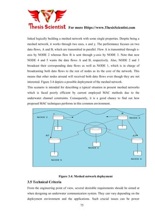
3.4 Target Scenario
The tests have been conducted over two scenarios:
• Scenario 1: Line-up network. The goal is to investigate how the data is disseminated
through nodes and how many time the data dissemination process takes](https://image.slidesharecdn.com/usnthesisnew-170510090413/85/Master-Thesis-on-Performance-Improvement-of-Underwater-Acoustic-Sensor-Network-using-Network-Coding-Algorithm-32-320.jpg)

![For more Https://www.ThesisScientist.com
76
consumption, throughput, reliability and scalability. In this section, some design factors
for underwater networks will be stated [33].
Signal Communication
According to previous statements, the most convenient technology for underwater
communication is upon acoustics in spite of its limiting factors. So, its channel effects
should be taken into account at an early design stage evaluating how they affect to the
design requirements. Note that range and data rate plays a key role in the selection of the
communication carrier.
Type of Cells
Depending on the environment and the distribution of nodes, omnidirectional or
directional antennas should be chosen for the design.
• Omni directional: Suitable for dynamic topologies where nodes are mobile and the
communication time between sender and receiver is limited.
• Directional: Appropriated for stationary communications where nodes are fixed. In this
scenario, the objective is to concentrate all the energy on a particular area
In this project, the nodes are supposed to transmit with omni-directional antennas though
the scenarios to conduct the tests are static, thus, the broadcast nature can be exploited.
Coverage Levels
As in each wireless communication system, the coverage study is a significant factor to
determine the system efficiency. It should fulfill the BER and SNR requirements at the
receiver to correctly demodulate the data packets. This analysis should also consider the
limiting factors of underwater propagation, sensitivity at the receiver, transmission power
and all those factors which are included in the power balance. The passive sonar equation
[33] characterizes the signal to noise ratio (SNRU) of an emitted underwater signal at the
receiver.
Underwater Deployment
The medium has strong influence on the deployment of an underwater network. In this
sense, performance varies drastically depending on depth, type of water and weather
conditions which affect seriously any underwater communications. To combat this
unpredictability, some underwater communications systems are designed for reliability](https://image.slidesharecdn.com/usnthesisnew-170510090413/85/Master-Thesis-on-Performance-Improvement-of-Underwater-Acoustic-Sensor-Network-using-Network-Coding-Algorithm-35-320.jpg)
![For more Https://www.ThesisScientist.com
77
even when operating in harsh conditions and these configurations lead to sub-optimal
performance when good propagation conditions exist. Part of the challenge in optimizing
performance is to predict which environmental factors have the greatest impact. A key
element to predicting channel characteristics is correctly estimate the multipath and this
is possible only if the properties of the boundaries are carefully modeled with simulation
tools or channel measurements when possible [33].
Energy Consumption
Energy efficiency is always a major concern to prolong the network time. As nodes are
battery-powered, recharging or replacing node batteries is difficult, especially in hard-to-
access areas such as the underwater environment. In order to cope this constraint there
are two solutions: the first is energetic based on the finding of optimal frequency for
underwater communication, the second solution is formal based on the choice of MAC
protocols essentially these of routing. That second approach is the basis of this project in
investigating the viability of proposed MAC techniques in underwater networks. NB.
Another approach in order to optimize energy utilization which is gaining more and more
attention in sensor networks is the power-sleeping mode, where devices alternate
between active and sleep mode. There is proved that the combination of both radio off
and microcontroller power down mode can significantly increase the network lifetime. A
particular work [34] proposes a cooperative mechanism for data distribution that
increases system reliability, and at the same time keeps the memory consumption for
data storage low on each device using previous approach.
Bandwidth
It is well known that the frequency-dependency of the acoustic path loss imposes a
bandwidth limitation on an underwater communication system. As sound waves are
much slower than the electromagnetic the latency in communication is typically much
higher. Due to the multi-path propagation and ambient noise, the effective data rates are
lower and packet loss rate is usually much greater. There are several approaches to
improve the bandwidth efficiency. One way to achieve high throughputs over band-
limited underwater acoustic channels could be to improve the receivers by using optimal
modulation and coding techniques. Many research focus on the PSK (Phase Shift](https://image.slidesharecdn.com/usnthesisnew-170510090413/85/Master-Thesis-on-Performance-Improvement-of-Underwater-Acoustic-Sensor-Network-using-Network-Coding-Algorithm-36-320.jpg)

![For more Https://www.ThesisScientist.com
79
if it is not taken into account. Also, the battery-powered network nodes limit the lifetime
of the proposed transceiver. Therefore, advanced signal processing is very important and
required to make optimum use of the transmission capabilities. To overcome these
difficulties, different modulations techniques and signaling encoding methods might
provide a feasible means for a more efficient use of the underwater acoustic channel
bandwidth. In fact, the values of the transmission loss, transmission distance and power
consumption, should be optimized to improve the wireless underwater communication
and the transceiver performance [27]. An important concern regarding wireless
transceiver for the underwater communication is its requirement of a transducer at the
transmitter side. This transducer allows to transform electrical waves into sound waves
and inversely.
CHAPTER 2
LITERATURE REVIEW
2.1Literature Review
Wireless acoustic sensor networks are helpful in a variety of applications i.e. tracking,
localization and home applications i.e. baby alarm systems. In these applications, the
networks are needed to position acoustic sources utilizing acoustic sensor arrays and this
has been employed in several security and environmental applications. In this paper [1]
,
various basic key aspects of underwater acoustic communications are inquired. Different
architectures for two-dimensional and three-dimensional USNs are talked about, and the
features of the underwater channel are described. The main issues for the development of
effective networking solutions posed by the underwater atmosphere are described and a
cross-layer technique to the combination of all communication functionalities is
proposed. Moreover, open research challenges are talked about and possible solution
techniques are outlined. Network coding is a method where, rather than simply relaying
the packets of information they achieve, the network nodes will take many packets and](https://image.slidesharecdn.com/usnthesisnew-170510090413/85/Master-Thesis-on-Performance-Improvement-of-Underwater-Acoustic-Sensor-Network-using-Network-Coding-Algorithm-38-320.jpg)
![For more Https://www.ThesisScientist.com
80
integrate them together for transmission. This can be utilized to achieve the maximum
possible information flow in a network. Network coding is a area of coding theory and
information theory. Network coding can enhance robustness, throughput, security and
complexity [2]
. In [3]
this paper they introduced UWMAC, a transmitter-based CDMA
MAC protocol for UWASNs that integrates a new closed-loop distributed algorithm to
establish the optimum transmit power and code length to decrease the near-far impact.
UW-MAC objective is to obtain three goals i.e. low channel access delay, high network
throughput and low energy consumption. It is shown that UW-MAC maintains to
simultaneously obtain limited channel access delay, high network throughput and low
energy consumption in deep water communications, which are not critically influenced
by multipath. Fatma Bouabdallah and Raouf Boutaba suggested UW-OFDMAC, a
distributed Medium Access Control (MAC) protocol which offers high bandwidth and
low energy consumption. By restricting Subcarrier Spacing Df and Guard Interval g T
they have indicated that the low energy consumption can be obtained. Subcarrier Spacing
should be selected so that the sub-carriers are orthogonal to each other, meaning that
cross-talk among the sub-carriers is removed or in other words Inter-Carrier interference
(ICI) is neglected. Guard Interval is inserted to neglect inter symbol disruption. A large
no. of closely spaced orthogonal sub-carrier signals to carry data. The data is classified
into many parallel data channels or streams, one for each subcarrier [4]
.
The writers introduced a new multi-path routing algorithm, which considering the energy
and distance into account to determine the path of transmission. The algorithm balances
the network energy consumption, increases the network‟s lifetime and enhances energy
efficiency. HMRLEACH algorithm put the energy on the first priority when selects the
path of transmission. HMR-LEACH algorithm would decrease the single path to energy
depletion process, increasing the network lifetime Period. Sink broadcast control package
first in a frequency to find the adjacent clusters, which refer to cluster that directly
transmit converged data to Sink. Then the adjacent clusters flood its own colour coded
information to non-adjacent cluster in the same frequency and proceed to flood until the
broadcast coverage of the whole network. If a cluster has obtained only one color-coded,
it indicates that the cluster has only one path leading to BS. If obtain multiple color-](https://image.slidesharecdn.com/usnthesisnew-170510090413/85/Master-Thesis-on-Performance-Improvement-of-Underwater-Acoustic-Sensor-Network-using-Network-Coding-Algorithm-39-320.jpg)
![For more Https://www.ThesisScientist.com
81
coded, showing that the cluster can be multi-paths to transmit data to sink nodes [5]
.
Depending on energy consumption analysis for LEACH in underwater channel, the
writers introduced a new mechanism for cluster-head selection to assure nodes energy
load balance by assuming the distance to SINK and residual energy of candidate nodes.
A cluster based network can be divided into disjoint clusters. Every cluster contains one
cluster head and several member nodes. Every cluster head gathers data from its member
nodes and relays the processed data. Depending on the analysis of energy of LEACH
protocol in underwater channel, a clustering mechanism for choosing and putting sensor
nodes into operation in every round is also introduced by utilizing a time metric,
according which the nodes throughout the network broadcast ADV, to assure the node
with more energy to become cluster head. Then it neglects selecting nodes with lower
residual energy and bad position as cluster-heads and then offers the energy load‟s
proportionality of sensor node [6]
. In [7]
, they introduce a new energy effective MAC
protocol known as NOGO-MAC (Node Grouped OFDMA MAC) which depend on
orthogonal frequency division multiple accesses (OFDMA) and exploit the physical
feature that propagation loss of acoustic wave based on the distance more heavily at high
frequency as compared to at low frequency. In the introduced scheme, sensor nodes are
collected according to the distance to sink node. Then, every group utilizes a different
frequency band in such a manner that sensor nodes which are nearer to the sink node
utilize higher frequency band and farther ones utilize lower frequency band. The
introduced technique not only enables all sensor nodes to manage the signal-to-noise
ratio above a specific needed level, but also decreases entire transmission power
consumption. Additionally, an adaptive sub channel allocation is used for improving data
transmission rate. In a WSN the sensor nodes are partitioned into many clusters
according to the sink position. At first, a sensor node in the cluster is elected in a random
way as the cluster head. Periodically, the sensor nodes in the same cluster will forward
its data to the head. The head combines the gathered data and then, forward these data
directly to the sink node. The process that sensor nodes forward the data to the head, the
head combined the gathered data and then, forward these data directly to the sink node is
termed as a round. After a round, every cluster will choose a new head. Maximal-energy](https://image.slidesharecdn.com/usnthesisnew-170510090413/85/Master-Thesis-on-Performance-Improvement-of-Underwater-Acoustic-Sensor-Network-using-Network-Coding-Algorithm-40-320.jpg)
![For more Https://www.ThesisScientist.com
82
mechanism chooses a head which consists the maximal energy of this cluster [8]
. In [9]
the
writers investigate the CHs selection in a distributed atmosphere i.e. MANET. They
obtain new results on the algorithmic complexity of two variants of the CH selection:
size-constrained clustering and distance-constrained clustering. The first variant such as
distance constrained chooses a group of CHs such that each network node is either a CH
or is positioned within distance h hops away from the closest CH. The second variant
such as size-constrained limits the maximum size of every cluster to members. A third
variant, integrating the distance and size constraints, is also shown. The distance-
constrained CH selection can determine a smaller CH set in comparison of the size-and-
distance-constrained selection. In this paper, a new, token-based medium access control
(TMAC) solution for underwater acoustic broadcast is proposed. TMAC offers a solution
to the synchronization issue, assuring efficient communication. TDMA protocols
partition a time interval called a frame into time slots. Every time slot is allocated to a
communication source. TDMA protocols in underwater acoustic networks need strict
synchronization. This TMAC solution neglects the requirement for synchronization and
thus underwrites successful communication [10]
. Borja Peleato and Milica Stojanovic
introduced Distance-Aware Collision Avoidance Protocol (DACAP) a non-synchronized
protocol that permits a node to utilize different hand-shake lengths for different
recipients so as to decrease the average handshake duration. This is obtained by taking
benefit of both the greater obtained power over short connections, and the computed
distance between the nodes. DACAP is a collision avoidance protocol that is simply
scalable to the changing no. of nodes and the network coverage region, and can be
analyzed for a specific network with very few restraints on the nodes. And it offers
higher throughput in comparison of Slotted FAMA with similar power efficiency [11]
. In
[12]
this paper, deployment methods of USN and gateway nodes for two-dimensional
communication architecture in Underwater Acoustic Wireless Sensor Networks
(UWSNs) are introduced. In the sensor deployment mechanism, underwater sensor nodes
are deployed in two rows along the coastline, which is of localization available, complete
coverage and connectivity and scalable. In the gateway deployment mechanism, the
gateway deployment is simulated as an optimization issue, by finding the underwater](https://image.slidesharecdn.com/usnthesisnew-170510090413/85/Master-Thesis-on-Performance-Improvement-of-Underwater-Acoustic-Sensor-Network-using-Network-Coding-Algorithm-41-320.jpg)
![For more Https://www.ThesisScientist.com
83
gateway nodes locations needed to achieve a provided design goal, which can be
minimal required delay and minimal required energy consumption. The writers measure
the performance of the mechanism by extensive simulations utilizing the OPNET
network simulator. The connectivity and coverage are significant standards of the sensor
deployment techniques in underwater acoustic wireless sensor networks (UWSNs). In [13]
this paper, the writers mainly research on the deployment of underwater sensors in
UWSNs. The benefits and drawbacks of some available algorithms are examined and an
enhanced algorithm is offered, which can obtain the complete connectivity and coverage.
Moreover, integrating with the localization problem, they deliberate a novel deployment
programmed, which is of complete connectivity and coverage, localization available and
scalable. The writers evaluate the performance of the programmed by extensive
simulations utilizing the OPNET network modeller. Unlike that of terrestrial sensor
networks, the physical layer design of Underwater Acoustic Sensor Networks (UW-
ASNs) faces far more issues due to the restricted band-width, refractive properties of the
medium, extended multipath, severe fading and large Doppler shifts. This paper
considers a tutorial overview of the physical features of acoustic propagation, modulation
techniques and power efficiency that are related to the physical layer design for
UWASNs, and examines the design consideration on every aspect. In the end, it presents
various open research problems, targeting to encourage research attempts to lay down
fundamental basis for the growth of new advanced underwater networking schemes in
the near future [14]
. LEACH protocol was introduced in [15]
. This is one of the clustering
routing protocols in WSNs. The benefit of LEACH is that every node has the equal
possibility to be a cluster head, which builds the energy dissipation of every node be
comparatively balanced. In LEACH protocol, time is partitioned into several rounds, in
every round, all the nodes contend to be cluster head according to a pre-specified
criterion. In [16]
this paper they introduce the new cluster head selection protocol i.e.
HEECH. This protocol chooses a best sensor node in terms of distance and energy as a
cluster head. The introduced protocol assumes the distance among cluster heads and BS
in multi hop and thus can solve the unbalancing energy consumption issue. As compared
to the LEACH, cluster heads in HEECH can utilize cluster heads of high level for data](https://image.slidesharecdn.com/usnthesisnew-170510090413/85/Master-Thesis-on-Performance-Improvement-of-Underwater-Acoustic-Sensor-Network-using-Network-Coding-Algorithm-42-320.jpg)
![For more Https://www.ThesisScientist.com
84
transmission. Hence energy consumption is balanced between the cluster heads and thus
the network lifetime is increased. In HEECH, every cluster heads directly forwards a
beacon message to the BS to announce itself left energy when the energy level is going
to be changed. Then BS is immediately broadcasts the obtained beacon message to the
cluster heads positioned at the lower level of the cluster head that its energy has changed
to declare its energy amount. Simulation Results indicate that the HEECH increases the
lifetime of network about 9% and 56% in comparison of the HEED and LEACH
respectively. A major concentration on the Acoustic Telemetry Group at Woods Hole
Oceanographic Institution (WHOI) has been the development of underwater acoustic
communication networks. Same as a cellular telephone network, an acoustic network
contains a no. of modems or nodes which adaptively transmit digital data packets
between scientific sensors and a viewing point or data collection. An important milestone
in the growth of such a network has been the latest establishment of a multichannel
adaptive recipient for coherent underwater communications. In paper [17]
, conventionally,
FEC (Forward Error Correction) and ARQ (Automatic Repeat Request) techniques have
been employed to tackle channel errors. In ARQ-based techniques, a sender resends a
packet if it obtains some feedback from either the destination node or next-hop that the
packet has been dropped, or if it observes a timeout. In the underwater acoustic channel,
an ARQ-based technique may induce long waiting time before a dropped packet can be
retransferred, hence exacerbating the long delays already caused by the slow propagation
speed. On the other side, FEC-based techniques add additional redundancy to the packet
before transmission. With limited bandwidth and energy restraints, as well as a highly
dynamic channel, the right amount of redundancy may be hard to determine. In current
years, network coding has become a very active research field. With network coding, an
intermediary node may integrate packets that it has prior obtained; this yields to higher
robustness against packet drops, however the destination node would still be capable to
extract the actual packets when it achieves an enough no. of packets that meets specific
properties. It has been indicated to be a promising scheme that could powerfully help
networks obtain high packet delivery ratio (PDR) as well as lower packet delays and
energy efficiency linear network coding encoded packet is a linear integration of the](https://image.slidesharecdn.com/usnthesisnew-170510090413/85/Master-Thesis-on-Performance-Improvement-of-Underwater-Acoustic-Sensor-Network-using-Network-Coding-Algorithm-43-320.jpg)
![For more Https://www.ThesisScientist.com
85
actual packets, and all computations are done over a finite field for any provided set of
actual packets. Acoustic waves are specifically pleased to underwater water wireless
communication because of the comparatively low absorption in underwater atmospheres.
The pathless, multipath and noise effects of the underwater terrain on acoustic waves are
explained in [20]
with comparison to optical and electromagnetic waves. They introduce
engineering counter measures in the form of physical layer schemes i.e. Direct Sequence
Spread Spectrum and multicarrier modulation i.e. orthogonal frequency division
multiplexing (OFDM) to mitigate the impact of channel non-idealities i.e. multipath.
Acoustic signals were also represented to provide lowest data rate, medium antenna
complexity and longest transmission range. Since, the impact of propagation delay,
particularly arising from this long transmission coverage, on the selection of modulation
is not treated. A network performance evaluation related to choice of medium access
control techniques (MAC) and different configurations is defined in [6]
. Chen and
Varshney [5]
, as well as Yigitel et al [31]
also provide some depth of insight into the
literature review in Quality of Service (QoS) support for wireless sensor networks
(WSNs). These works and other reviews [2,5,9,23]
without knowledge share a common
theme on the reliability of design and wireless sensor networks implementation. While
this has explored the application to various different fields, it has also generated
divergent views, resulting in deficiency of standardization and diverse application-
specific needs. As specified in [28]
, this has stripped WSNs from having a single de-facto
standard MAC protocol. While, these techniques have obtained remarkable levels of
efficiency, when the packets gain access to the medium, non-idealities of the channel
take their toll on the transferred packets and medium access control techniques can no
longer ensure the packets conditions when they reach at the sink; regardless of the QoS
measures implemented. The aforesaid references do not take cognizance of the available
of these non-idealities in the results shown hence building such results rather optimistic.
According to [14]
, incorporating non-ideal situations i.e. path loss and multipath fading
into the simulation exerts a non-negligible effect on the wireless local area networks
performance. However, the wireless acoustic signal utilized in WASNs is also subject to
same intrinsic channel impacts, this sets the stage for a similar investigation into the](https://image.slidesharecdn.com/usnthesisnew-170510090413/85/Master-Thesis-on-Performance-Improvement-of-Underwater-Acoustic-Sensor-Network-using-Network-Coding-Algorithm-44-320.jpg)
![For more Https://www.ThesisScientist.com
86
effect on WASN performance The starting point for such investigation starts with a
observation that the information transmission over a channel is achieved by mapping the
digital information to a sequence of symbols which vary some features of an
electromagnetic wave known as the carrier. This procedure is known as modulation, and
is responsible for message signal transmission through the communication channel with
the best possible quality [23]
. Thus the choice of a modulation technique that is robust to
channel impairments is always an interesting concern for communication systems, and
more so when the channel is a wireless medium. The study in [24]
concentrated on
traditional narrowband modulation mechanisms i.e. quadrature amplitude modulation
(QAM) and differential phase shift keying (DPSK) and the results indicate that these
techniques cannot be depend on to mitigate network performance reduction in the
existence of non-ideal channel situations. Since, it is well established in literature [32,33]
that translating the narrowband signal to a wideband signals before transmission
decreases the impact of channel non-idealities i.e. multipath. The traditional scheme for
narrowband to wideband signal conversion is the usage of pseudo-noise (PN) sequences
and is further explained in chapter two. Worthy of note however, is that most available
research works [10,14]
acknowledge that traditional broadband modulation techniques,
otherwise known as spread spectrum mechanisms provide excellent performance in
mitigating the impact of non-ideal channel conditions, and especially excel in
importantly decreasing the impact of multipath. In [15]
, Kennedy et al. propose the
application of an alternative spread spectrum scheme to WLANs. This optional technique
is derived from the evolving field of chaos communication where the information to be
transferred is mapped to chaotic signals (rather than PN sequences) which are robust to
multipath and reputed to be inherently wideband [1,28]
. It was shown, through noise
performance comparison (AWGN), that the performance of chaos modulation techniques
is worse than those of the traditional broadband techniques with their performance
restrictions stemming from their chaotic features [18,25]
. Citing the availability of other
non-ideal application scenarios i.e. industrial application, where the channel impairments
go beyond the ideal scope of AWGN, Kennedy et al. introduce the application of a chaos
modulation technique to WLANs. They provide support to the proposal by highlighting](https://image.slidesharecdn.com/usnthesisnew-170510090413/85/Master-Thesis-on-Performance-Improvement-of-Underwater-Acoustic-Sensor-Network-using-Network-Coding-Algorithm-45-320.jpg)
![For more Https://www.ThesisScientist.com
87
many benefits provided by chaos modulation techniques i.e. demodulation without
carrier synchronization as well as simple circuitry. These were also specified to be
downsides for traditional spread spectrum mechanisms. This makes a good platform for
the new work performed by Leung et.al in [22]
and the comparison in [25]
. These works,
since, concentrates on the physical layer and network performance comparisons are not
involved in the results.
CHAPTER 3
BACKGROUND STUDY
3.1 Underwater Acoustic Sensor Networks Communication
Architecture](https://image.slidesharecdn.com/usnthesisnew-170510090413/85/Master-Thesis-on-Performance-Improvement-of-Underwater-Acoustic-Sensor-Network-using-Network-Coding-Algorithm-46-320.jpg)
![For more Https://www.ThesisScientist.com
88
In this section, we describe the communication architecture of underwater acoustic
sensor networks. The reference architectures described in this section are used as a basis
for discussion of the challenges associated with underwater acoustic
Fig. 3.1 Architecture for 2D Underwater Sensor Networks
sensor networks [21]. The underwater sensor network topology is an open research issue
in itself that needs further analytical and simulative investigation from the research
community. In the remainder of this section, we discuss the following architectures:
Static two-dimensional UW-ASNs for ocean bottom monitoring. These are
constituted by sensor nodes that are anchored to the bottom of the ocean. Typical
applications may be environmental monitoring, or monitoring of underwater plates in
tectonics [4].
Static three-dimensional UW-ASNs for ocean column monitoring. These include
networks of sensors whose depth can be controlled by means of techniques discussed in
Section II-B, and may be used for surveillance applications or monitoring of ocean
phenomena (ocean biogeochemical processes, water streams, pollution, etc).
A. Two-dimensional Underwater Sensor Networks](https://image.slidesharecdn.com/usnthesisnew-170510090413/85/Master-Thesis-on-Performance-Improvement-of-Underwater-Acoustic-Sensor-Network-using-Network-Coding-Algorithm-47-320.jpg)
![For more Https://www.ThesisScientist.com
89
Reference architecture for two-dimensional underwater networks is shown in Fig. 2.1. A
group of sensor nodes are anchored to the bottom of the ocean with deep ocean anchors.
By means of wireless acoustic links, underwater sensor nodes are interconnected to one
or more underwater sinks (uw-sinks), which are network devices in charge of relaying
data from the ocean bottom network to a surface station. To achieve this objective, uw-
sinks are equipped with two acoustic transceivers, namely a vertical and a horizontal
transceiver [20]. The horizontal transceiver is used by the uw-sink to communicate with
the sensor nodes in order to: i) send commands and configuration data to the sensors
(uw-sink to sensors); ii) collect monitored data (sensors to uw-sink). The vertical link is
used by the uw links to relay data to a surface station. Vertical transceivers must be long
range transceivers for deep water applications as the ocean can be as deep as 10 km. The
surface station is equipped with an acoustic transceiver that is able to handle multiple
parallel communications with the deployed uw-sinks. It is also endowed with a long
range RF and/or satellite
Fig. 3.2 Architecture for 3D Underwater Sensor Networks
Design Criteria](https://image.slidesharecdn.com/usnthesisnew-170510090413/85/Master-Thesis-on-Performance-Improvement-of-Underwater-Acoustic-Sensor-Network-using-Network-Coding-Algorithm-48-320.jpg)
![For more Https://www.ThesisScientist.com
90
The development of practical underwater networks is a difficult task that requires a broad
range of skills. Not only must the physical layer provide reliable links in all
environmental conditions, but there are a host of protocols that are required to support
the network discovery and maintenance as well as interoperability, message formation,
and system security [28]. As electromagnetic waves do not propagate well underwater,
acoustics plays a key role in underwater communication. Due to significant differences
in the characteristics of electromagnetic and acoustic channels, the design of feasible
underwater networks needs to take into account a wide variety of different constraints.
The long delays, frequency-dependence and extreme limitations in achievable bandwidth
and link range of acoustics should be of primary concern at an early design stage in
addition to power and throughput efficiency, and system reliability. These factors make
underwater networking a challenging and rewarding endeavour. In this chapter, some
significant aspects to be considered when designing an underwater communication
system are analyzed. For example, the description of the environment where the network
is supposed to be deployed, technical criteria and general assumptions [18].
3.2 Challenges
The design of underwater networks involves many topics covering physical and
networking capabilities. As acoustic channels are commonly used for underwater
communications, the main focuses in this project are the state of- the-art analysis of
commercial acoustic modems and suppliers as well as the design and possible
implementation of Medium Access with Interference Cancellation and Network Coding
(main part). While some Medium Access schemes have been successful in traditional
radio communications, they are prone to severe limitations in efficiency and scalability
when employed in the underwater environment posing many challenges to networking
protocol design. For example, in Medium Access Control (MAC) schemes which operate
entirely in the time domain (for instance, TDMA and CSMA), these disadvantages are
primarily because of the very large propagation delays [31]. Therefore, new strategies are
needed in order to account the specific features of underwater propagation. Some design
challenges for reliable data transport in UWSNs [32] could be as follows:](https://image.slidesharecdn.com/usnthesisnew-170510090413/85/Master-Thesis-on-Performance-Improvement-of-Underwater-Acoustic-Sensor-Network-using-Network-Coding-Algorithm-49-320.jpg)
![For more Https://www.ThesisScientist.com
91
1. End-to-End approach does not work well due to the high channel error probability and
the low propagation speed of acoustic signals
2. Half-Duplex acoustic channels limit the choice of complex ARQ protocols
3. Too many feedback from receivers are not desirable in terms of energy consumption
4. Very large bulk data transmission is not suitable in mobile UWSNs because of the
limited communication time between any pair of sender and receiver, the low bandwidth
and the long propagation delay
3.3 Assumptions
The main goal of this project is to investigate how Medium Access with Interference
Cancellation and Network Coding perform regarding data dissemination as compared
with employed MAC techniques underwater. In this sense, some tests are conducted in
order to evaluate the performance. Consequently, general assumptions should be stated
to understand how the tests are carried out. In this project, an underwater network is
simply defined as a set of nodes which communicate using acoustics waves. The nodes
are fixed and the distance among them is considered in the long range; a typical range
between transmitter and receiver could be 1 km. Despite being a stationary network,
mobile scenarios where nodes can passively float with water currents are also taken into
account for explanations. The coverage range of a node is one hop. This means that the
level of signal which is received by next hop node is very high, otherwise, is very low.
Typical values used in mobile communications systems are 90% and 10%, respectively.
So, it is assumed that the signal from a source node will not be received by nodes whose
range is higher than one hop. Likewise, regarding the sound propagation speed, its
nominal value 1500 m/s is used for calculations. Another relevant aspect which should
be assumed in the performance evaluation of Medium Access schemes is the packet
length. Hence, the packet size is set basing on two approaches. First, the transmission
capacity of nodes is considered without data redundancy. Second, the packet
transmission time is equals to the propagation delay depending on the distance between
sender and receiver [30].](https://image.slidesharecdn.com/usnthesisnew-170510090413/85/Master-Thesis-on-Performance-Improvement-of-Underwater-Acoustic-Sensor-Network-using-Network-Coding-Algorithm-50-320.jpg)
![For more Https://www.ThesisScientist.com
92
On the other hand, it should be mentioned that the node with greater impact on the
network is supposed to implement Interference Cancellation and Network Coding
whereas the other nodes are in charge of data packet retransmission using Interference
Cancellation. Besides, a two-way communication (upstream and downstream flows),
unlimited storage capacity of terminals and kjno packet erasures are assumed to conduct
the experiments. Finally, the dissemination process is completed when the target nodes
have received all the requested packets [31].
3.4 Target Scenario
The tests have been conducted over two scenarios:
• Scenario 1: Line-up network. The goal is to investigate how the data is disseminated
through nodes and how many time the data dissemination process takes
• Scenario 2: Meshed network. The aim is to analyze the performance of proposed MAC
methods in such common topologies: dense traffic situations in large-scale networks
3.4.1 Line-up Network
This scenario consists of 5 nodes which are aligned either vertically or horizontally. They
are named and organized from left to right as ”NODE X”. Each node is logically linked
with its upstream and downstream nodes. Figure 3.3 shows the horizontal deployment of
the line-up network.](https://image.slidesharecdn.com/usnthesisnew-170510090413/85/Master-Thesis-on-Performance-Improvement-of-Underwater-Acoustic-Sensor-Network-using-Network-Coding-Algorithm-51-320.jpg)
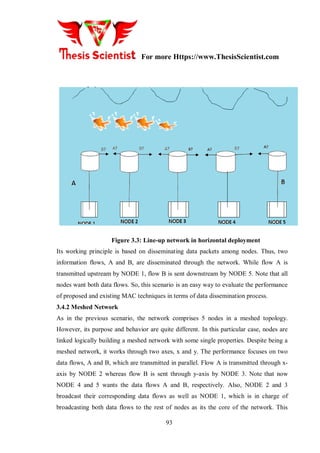
![For more Https://www.ThesisScientist.com
94
means that other nodes around will received both data flows even though they are not
interested. Figure 3.4 depicts a possible deployment of the meshed network.
This scenario is intended for describing a typical situation in present meshed networks
which is faced poorly efficient by current employed MAC methods due to the
underwater channel constraints. Consequently, it is a good chance to find out how
proposed MAC techniques performs in this common environment.
Figure 3.4: Meshed network deployment
3.5 Technical Criteria
From the engineering point of view, several desirable requirements should be aimed at
when designing an underwater communication system. They can vary depending on the
deployment environment and the applications. Such crucial issues can be power
consumption, throughput, reliability and scalability. In this section, some design factors
for underwater networks will be stated [33].
Signal Communication
According to previous statements, the most convenient technology for underwater
communication is upon acoustics in spite of its limiting factors. So, its channel effects
should be taken into account at an early design stage evaluating how they affect to the](https://image.slidesharecdn.com/usnthesisnew-170510090413/85/Master-Thesis-on-Performance-Improvement-of-Underwater-Acoustic-Sensor-Network-using-Network-Coding-Algorithm-53-320.jpg)
![For more Https://www.ThesisScientist.com
95
design requirements. Note that range and data rate plays a key role in the selection of the
communication carrier.
Type of Cells
Depending on the environment and the distribution of nodes, omnidirectional or
directional antennas should be chosen for the design.
• Omni directional: Suitable for dynamic topologies where nodes are mobile and the
communication time between sender and receiver is limited.
• Directional: Appropriated for stationary communications where nodes are fixed. In this
scenario, the objective is to concentrate all the energy on a particular area
In this project, the nodes are supposed to transmit with omni-directional antennas though
the scenarios to conduct the tests are static, thus, the broadcast nature can be exploited.
Coverage Levels
As in each wireless communication system, the coverage study is a significant factor to
determine the system efficiency. It should fulfill the BER and SNR requirements at the
receiver to correctly demodulate the data packets. This analysis should also consider the
limiting factors of underwater propagation, sensitivity at the receiver, transmission power
and all those factors which are included in the power balance. The passive sonar equation
[33] characterizes the signal to noise ratio (SNRU) of an emitted underwater signal at the
receiver.
Underwater Deployment
The medium has strong influence on the deployment of an underwater network. In this
sense, performance varies drastically depending on depth, type of water and weather
conditions which affect seriously any underwater communications. To combat this
unpredictability, some underwater communications systems are designed for reliability
even when operating in harsh conditions and these configurations lead to sub-optimal
performance when good propagation conditions exist. Part of the challenge in optimizing
performance is to predict which environmental factors have the greatest impact. A key
element to predicting channel characteristics is correctly estimate the multipath and this
is possible only if the properties of the boundaries are carefully modeled with simulation
tools or channel measurements when possible [33].](https://image.slidesharecdn.com/usnthesisnew-170510090413/85/Master-Thesis-on-Performance-Improvement-of-Underwater-Acoustic-Sensor-Network-using-Network-Coding-Algorithm-54-320.jpg)
![For more Https://www.ThesisScientist.com
96
Energy Consumption
Energy efficiency is always a major concern to prolong the network time. As nodes are
battery-powered, recharging or replacing node batteries is difficult, especially in hard-to-
access areas such as the underwater environment. In order to cope this constraint there
are two solutions: the first is energetic based on the finding of optimal frequency for
underwater communication, the second solution is formal based on the choice of MAC
protocols essentially these of routing. That second approach is the basis of this project in
investigating the viability of proposed MAC techniques in underwater networks. NB.
Another approach in order to optimize energy utilization which is gaining more and more
attention in sensor networks is the power-sleeping mode, where devices alternate
between active and sleep mode. There is proved that the combination of both radio off
and microcontroller power down mode can significantly increase the network lifetime. A
particular work [34] proposes a cooperative mechanism for data distribution that
increases system reliability, and at the same time keeps the memory consumption for
data storage low on each device using previous approach.
Bandwidth
It is well known that the frequency-dependency of the acoustic path loss imposes a
bandwidth limitation on an underwater communication system. As sound waves are
much slower than the electromagnetic the latency in communication is typically much
higher. Due to the multi-path propagation and ambient noise, the effective data rates are
lower and packet loss rate is usually much greater. There are several approaches to
improve the bandwidth efficiency. One way to achieve high throughputs over band-
limited underwater acoustic channels could be to improve the receivers by using optimal
modulation and coding techniques. Many research focus on the PSK (Phase Shift
Keying) modulation, which are a viable way of achieving high speed data transmission.
This topic is also included in this project as an important research task. For this reason,
the state-of-the-art analysis of current commercial acoustic modems will be discussed
later.
Reliability](https://image.slidesharecdn.com/usnthesisnew-170510090413/85/Master-Thesis-on-Performance-Improvement-of-Underwater-Acoustic-Sensor-Network-using-Network-Coding-Algorithm-55-320.jpg)

![For more Https://www.ThesisScientist.com
98
bandwidth. In fact, the values of the transmission loss, transmission distance and power
consumption, should be optimized to improve the wireless underwater communication
and the transceiver performance [27]. An important concern regarding wireless
transceiver for the underwater communication is its requirement of a transducer at the
transmitter side. This transducer allows to transform electrical waves into sound waves
and inversely.
CHAPTER 4
PROPOSED WORK
In this chapter, we shall offer the details of network coding operation at a node and along
the network data path. Then we implement them in the RIVERBED process models and
node models that are utilized in our simulations in the paper. Any general consideration
utilized in our performance analysis and evaluation is offered at the end.](https://image.slidesharecdn.com/usnthesisnew-170510090413/85/Master-Thesis-on-Performance-Improvement-of-Underwater-Acoustic-Sensor-Network-using-Network-Coding-Algorithm-57-320.jpg)


![For more Https://www.ThesisScientist.com
108
appended to corresponding sub queues with respect to its traffic stream. If the server is
not busy and all sub queues have a packet, it enters the “svc_start” state where the coding
operation as explained in Figure 3.4 will occur. Then it enters the “idle” state to wait for
the service of the coded packet to complete (this is what we often call the packet
transmission time). At the transmission end, the “svc_compl” event will be triggered by a
self interrupt, and the procedure goes to svc_compl state where the packet is eliminated
from the node buffer. After this, the procedure will enter in the idle state to wait for
another packet arrival if the sub queue has become empty, or it enters the “svc_start”
state again to serve (perform network coding) on another group of packets if they are
available in all sub queues. Observe that the “idle” state permits a packet to wait for
several events as observed while the init state is a trivial state to start the process. Except
for the NC process model and the coding node model, we also require to produce some
other process models and node models to complete the simulation of network. They are:
a. Source node: It contains a source process model, a source generator and one or more
point to point transmitters.
b. Sink node: It contains a sink process, a decoding process and some point to point
recipients.
In addition to these process models and node models, we also require to generate the
link model to make the entire RIVERBED project.
4.4.3 Pipeline Stages
A pipeline stage is an RIVERBED object that permits a communication channel property
to be simulated. However radio connections offer a broadcast medium, every
transmission can potentially influence numerous receivers over the network model. A
radio connection to every recipient can also have different timing and behavior. So a
separate pipeline must be executed for each eligible recipient [RIVERBED14] to account
for all the communications with other radio connections.](https://image.slidesharecdn.com/usnthesisnew-170510090413/85/Master-Thesis-on-Performance-Improvement-of-Underwater-Acoustic-Sensor-Network-using-Network-Coding-Algorithm-67-320.jpg)
![For more Https://www.ThesisScientist.com
109
Figure 4.11: Underwater Acoustic Transceiver Pipeline Stages
Figure 4.11 is the acoustic transceiver pipeline stages we utilize for our underwater
network. RIVERBED. There are 14 stages executed in sequence to model the
transmission channel state for every packet transmission. These stages are copied directly
from the radio transceiver pipeline stage from [RIVERBED14] except that we have to
change the parameter values and equations utilized for the wireless air channel for
characterizing the underwater channels that we require in Ch.4. for matching the unique
underwater characteristics, we require to revise the propagation delay phase, the recipient
power phase and the background noise phase.
4.5 Assumptions
Unless otherwise mentioned, the following considerations pertain to the remainder of this
thesis.](https://image.slidesharecdn.com/usnthesisnew-170510090413/85/Master-Thesis-on-Performance-Improvement-of-Underwater-Acoustic-Sensor-Network-using-Network-Coding-Algorithm-68-320.jpg)


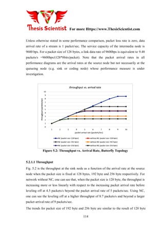

![For more Https://www.ThesisScientist.com
116
network coding. Also, throughput saturation arrival rate is about 80% higher than
without network coding. On passing, we note that the maximum throughput of 8.7
packets/sec attained by NC is very close to the theoretical limit of 9.47 packets/sec based
on the Max-Flow Min-Cut Theorem [PaSt98].
Figure 5.3: End To End Delay vs Arrival Rate, Butterfly Topology
5.2.1.2 ETE Delay
Figure 5.3 is the average end-to-end delay at the sink node as a function of the arrival
rates at the source node when the packet size is fixed at 128 bytes. For the network
without network coding, the delay is first constant with respect to increasing packet
arrival rate, but is building up quickly beyond the packet arrival rate of 4.4 packets/sec.
This can be explained by the D/D/1 behavior because the arrival to the node is modulated
by the departure process of the upstream node. Since the service time of each packet is
fixed, so it would appear that the packets are departing deterministically when the queue
is non-empty (usually at high arrival rates to the node). When the arrival rate increase
beyond the service rate at node C, the system become unstable. For network with NC, we
can see the ETE delay is always lower. The delay is first decreasing with increasing
packet arrival rate because a packet is more likely to find another packet at the other data
stream to perform coding at higher arrival rate instead of waiting for the other packet
when packet arrival rate is very low. Furthermore, the delay remains stable beyond the](https://image.slidesharecdn.com/usnthesisnew-170510090413/85/Master-Thesis-on-Performance-Improvement-of-Underwater-Acoustic-Sensor-Network-using-Network-Coding-Algorithm-75-320.jpg)


![For more Https://www.ThesisScientist.com
125
For network without NC, one can see that, when packet size is 128 byte, the throughput
is increasing more or less linearly with respect to the packet arrival rate before leveling
off at a throughput of 2.8 packets/sec when the packet arrival rate goes beyond 6
packets/sec. With NC, we can see the leveling off is at a higher throughput of 7.4
packets/sec when the packet arrival rate beyond 8 packets/sec. Note that this maximum
throughput of 7.4 packets/sec using NC is very close to the theoretical limit of 7.4
packets/sec predicted by the Max-Flow Min-Cut Theorem [PaSt98].
Figure 5.9: Throughput vs. Packet Arrival Rate of the Multi-Relay Network
The trends for packet size of 192 byte and 256 byte are similar to the result of 128 byte
except the throughputs are lower (at 5.8 packet/s and 4.6 packets/s respectively) and the
leveling off points occur earlier (when going beyond arrival rates of 6 packets/s and 4
packets/s respectively).](https://image.slidesharecdn.com/usnthesisnew-170510090413/85/Master-Thesis-on-Performance-Improvement-of-Underwater-Acoustic-Sensor-Network-using-Network-Coding-Algorithm-84-320.jpg)


![For more Https://www.ThesisScientist.com
137
The trends for packet sizes of 192 byte and 256 byte are similar to the result for a packet
size of 128 byte, except that the maximum throughputs are lower and the leveling off
point occurs earlier. In scenario without NC, the throughputs level off at 2.5 packets/sec
and 2.1 packets/sec respectively, when arrival rates go beyond 5 packet/sec and 4
packets/sec respectively. In scenario with NC, the throughputs levels are 5.2 packets/sec
and 4.2 packets/sec respectively for arrival rates beyond 6 packet/sec and 5 packets/sec
respectively. The maximum throughput obtained by Max-Flow Min-Cut [PaSt98] theory
is 7.44 packets/sec for this network, which is almost achieved by NC.
Figure 5.14 .2: Throughout vs. Packet Arrival Rate in a Big Network
Figure 5.14b is the throughput seen at a sink node (both T1 and T2 are symmetrical in
performance) as a function of the packet arrival rate at source node in the big network
with different packet loss rates in a link. When the packet loss rate is 0.2, the network
throughput without NC is increasing more or less linearly with respect to the increasing
packet arrival rate before leveling off at 4.6 packets/s beyond the packet arrival rate of 7
packets/sec. Using NC, one can see the leveling off occurs at a higher level of 6.2
packets/s and beyond a higher packet arrival rate of 9 packets/sec. The maximum
throughout achieved by NC is about twice that of network without NC. The trends for](https://image.slidesharecdn.com/usnthesisnew-170510090413/85/Master-Thesis-on-Performance-Improvement-of-Underwater-Acoustic-Sensor-Network-using-Network-Coding-Algorithm-96-320.jpg)


![Https://www.ThesisScientist.com
REFERENCES
[1] A. Abel and W. Schwarz, "Chaos communications-principles, schemes, and system
analysis," Proc IEEE, vol. 90, pp. 691-710, 2002.
[2] I. F. Akyildiz, W. Su, Y. Sankarasubramaniam and E. Cayirci, "A survey on sensor
networks," Communications Magazine, IEEE, vol. 40, pp. 102-114, 2002.
[3] I. F. Akyildiz and M. C. Vuran, Wireless Sensor Networks. John Wiley & Sons, 2010.
[4] I. T. Almalkawi, M. G. Zapata, J. N. Al-Karaki and J. Morillo-Pozo, "Wireless
Multimedia Sensor Networks: current trends and future directions," Sensors (Basel), vol.
10, pp. 6662-6717, 2010.
[5] D. Chen and P. K. Varshney, "QoS support in wireless sensor networks: A survey." in
International Conference on Wireless Networks, 2004, pp. 1-7.
[6] J. dos Santos Coelho, Underwater Acoustic Networks: Evaluation of the Impact of
Media Access Control on Latency, in a Delay Constrained Network, 2005.
[7] M. Erol-Kantarci, H. T. Mouftah and S. Oktug, "A survey of architectures and
localization techniques for underwater acoustic sensor networks," Communications
Surveys & Tutorials, IEEE, vol. 13, pp. 487-502, 2011.
[8] A. M. Fabregat, A. M. Fabregat and A. M. Fabregat, "Desenvolupament, proves de
camp i anàlisi de resultats en una," 2008.
[9] N. Ismail, L. A. Hussein and S. H. Ariffin, "Analyzing the performance of acoustic
channel in underwater wireless sensor network (UWSN)," in Mathematical/Analytical
Modelling and Computer Simulation (AMS), 2010 Fourth Asia International Conference
on, 2010, pp. 550-555.
[10] Jákó, Zoltán. "Performance Improvement of Differential Chaos Shift Keying
Modulation Scheme." Thesis submitted to the Department of Measurement and
Information Systems. Budapest University of Technology and Economics.
[11] M. C. Jeruchim, P. Balaban and K. S. Shanmugan, Simulation of Communication
Systems: Modeling, Methodology and Techniques. Springer, 2000.
[12] P. Jurčík and A. Koubâa, "The IEEE 802.15. 4 OPNET simulation model: reference
guide v2. 0," IPP-HURRAY Technical Report, HURRAY-TR-070509, 2007.](https://image.slidesharecdn.com/usnthesisnew-170510090413/85/Master-Thesis-on-Performance-Improvement-of-Underwater-Acoustic-Sensor-Network-using-Network-Coding-Algorithm-106-320.jpg)
![Https://www.ThesisScientist.com
[13] G. Kaddoum, J. Olivain, G. Beaufort Samson, P. Giard and F. Gagnon,
"Implementation of a differential chaos shift keying communication system in gnu radio,"
in Wireless Communication Systems (ISWCS), 2012 International Symposium on, 2012,
pp. 934-938.
[14] M. P. Kennedy and G. Kolumbán, "Digital communications using chaos," Signal
Process, vol. 80, pp. 1307-1320, 2000.
[15] M. P. Kennedy, G. Kolumbán, G. Kis and Z. Jákó, "Performance evaluation of FM-
DCSK modulation in multipath environments," 2000.
[16] M. Kennedy, R. Rovatti and G. Setti, Chaotic Electronics in Telecommunications.
CRC press, 2000.
[17] G. KOLUMBaN, K. GaBOR, J. Zoltan and M. P. Kennedy, "FM-DCSK: A robust
modulation scheme for chaotic communications," IEICE Trans. Fund. Electron. Commun.
Comput. Sci., vol. 81, pp. 1798-1802, 1998.
[18] G. Kolumban, M. P. Kennedy, Z. Jákó and G. Kis, "Chaotic communications with
correlator receivers: theory and performance limits," 2002.
[19] G. Kolumban and T. Krébesz, "UWB radio: A real chance for application of chaotic
communications," Proc.NOLTA‟06, pp. 475-478, 2006.
[20] Kennedy, Michael Peter, and Géza Kolumbán. "Digital communications using
chaos." Signal processing 80.7 (2000): 1307-1320.
[21] F. C. Lau and K. T. Chi, Chaos-Based Digital Communication Systems: Operating
Principles, Analysis Methods, and Performance Evaluation. Springer, 2003.
[22] H. Leung, H. Yu and K. Murali, "Ergodic chaos-based communication schemes,"
Physical Review E, vol. 66, pp. 036203, 2002.
[23] H. Leung, S. Shanmugam, N. Xie and S. Wang, "An ergodic approach for chaotic
signal estimation at low SNR with application to ultra-wide-band communication," Signal
Processing, IEEE Transactions on, vol. 54, pp. 1091-1103, 2006.
[24] Y. Liu, I. Elhanany and H. Qi, "An energy-efficient QoS-aware media access control
protocol for wireless sensor networks," in Mobile Adhoc and Sensor Systems Conference,
2005, IEEE International Conference on, 2005, pp. 3 pp.-191](https://image.slidesharecdn.com/usnthesisnew-170510090413/85/Master-Thesis-on-Performance-Improvement-of-Underwater-Acoustic-Sensor-Network-using-Network-Coding-Algorithm-107-320.jpg)
![Https://www.ThesisScientist.com
[25] M. Lujuan, "Hybrid DCSK/TDMA Multi-Rate MAC Protocol for Underwater
Acoustic Sensor Networks," JDCTA: International Journal of Digital Content Technology
and its Applications, vol. 6, pp. 565~ 572-565~ 572.
[26] S. Mandal and S. Banerjee, "Performance of differential chaos shift keying
communication over multipath fading channels," in National Conference on Nonlinear
Systems & Dynamics, 2002, pp. 1-4.
[27] F. Nekoogar, Ultra-Wideband Communications: Fundamentals and Applications.
Prentice Hall Press, 2005.
[28] F. S. Netto and M. Eisencraft, "Spread spectrum digital communication system using
chaotic pattern generator," in 10th Experimental Chaos Conference, Catania, 2008.
[29] N. Patwari, J. N. Ash, S. Kyperountas, A. O. Hero, R. L. Moses and N. S. Correal,
"Locating the nodes: cooperative localization in wireless sensor networks," Signal
Processing Magazine, IEEE, vol. 22, pp. 54-69, 2005.
[30] L. M. Pecora and T. L. Carroll, "Synchronization in chaotic systems," Phys. Rev.
Lett., vol. 64, pp. 821-824, Feb 19, 1990.
[31] U. Pešović, J. Mohorko, K. Benkič and Ž. Čučej, "Effect of hidden nodes in IEEE
802.15. 4/ZigBee wireless sensor networks," in XVII Telecommunications Forum-
TELFOR, 2009, pp. 24-26.
[32] J. G. Proakis, "Digital Communications Fourth Edition, 2001," 1998
[33] T. Rappaport, "Wireless Communications Principles and Practice Second Edition,
2002,"
[34] Z. Ren, G. Wang, Q. Chen and H. Li, "Modelling and simulation of Rayleigh fading,
path loss, and shadowing fading for wireless mobile networks," Simulation Modelling
Practice and Theory, vol. 19, pp. 626-637, 2011.
[35] J. Rice, "SeaWeb acoustic communication and navigation networks," in Proceedings
of the International Conference on Underwater Acoustic Measurements: Technologies and
Results, 2005.
[36] R. Rovatti, G. Mazzini and G. Setti, "Enhanced rake receivers for chaos-based DS-
CDMA," Circuits and Systems I: Fundamental Theory and Applications, IEEE
Transactions on, vol. 48, pp. 818-829, 2001.](https://image.slidesharecdn.com/usnthesisnew-170510090413/85/Master-Thesis-on-Performance-Improvement-of-Underwater-Acoustic-Sensor-Network-using-Network-Coding-Algorithm-108-320.jpg)
![Https://www.ThesisScientist.com
[37] A. Savvides, H. Park and M. B. Srivastava, "The bits and flops of the n-hop multi
alteration primitive for node localization problems," in Proceedings of the 1st ACM
International Workshop on Wireless Sensor Networks and Applications, 2002, pp. 112-
121
[38] N. Saxena, A. Roy and J. Shin, "Dynamic duty cycle and adaptive contention window
based QoS-MAC protocol for wireless multimedia sensor networks," Computer Networks,
vol. 52, pp. 2532-2542, 2008.
[39] R. Severino and M. Alves, "Engineering a search and rescue application with a
wireless sensor network-based localization mechanism," in World of Wireless, Mobile and
Multimedia Networks, 2007. WoWMoM 2007. IEEE International Symposium on a,
2007, pp. 1-4.
[40] E. M. Sozer, M. Stojanovic and J. G. Proakis, "Underwater acoustic networks,"
Oceanic Engineering, IEEE Journal of, vol. 25, pp. 72-83, 2000.
[41] E. M. Sozer, M. Stojanovic and J. G. Proakis, "Design and simulation of an
underwater acoustic local area network," in Proc. Opnetwork‟99, 1999, .
[42] R. D. Standfield, OPNET Implementation of Spread Spectrum Network for Voice
and Data Distribution., 1997.
[43] M. Stojanovic, "On the relationship between capacity and distance in an underwater
acoustic communication channel," ACM SIGMOBILE Mobile Computing and
Communications Review, vol. 11, pp. 34-43, 2007
[44] M. Stojanovic, "Underwater acoustic communications," in Electro/95 International.
Professional Program Proceedings, 1995, pp. 435-440.
[45] M. Sushchik, L. S. Tsimring and A. R. Volkovskii, "Performance analysis of
correlation-based communication schemes utilizing chaos," Circuits and Systems I:
Fundamental Theory and Applications, IEEE Transactions on, vol. 47, pp. 1684-1691,
2000.
[46] A. J. Viterbi, "Wireless digital communication: A view based on three lessons
learned," IEEE Communications Magazine, vol. 29, pp. 33-36, 1991.
[47] M. C. Vuran and I. F. Akyildiz, "Cross-layer packet size optimization for wireless
terrestrial, underwater, and underground sensor networks," in INFOCOM 2008, the 27th
Conference on Computer Communications. IEEE, 2008](https://image.slidesharecdn.com/usnthesisnew-170510090413/85/Master-Thesis-on-Performance-Improvement-of-Underwater-Acoustic-Sensor-Network-using-Network-Coding-Algorithm-109-320.jpg)
![Https://www.ThesisScientist.com
APPENDIX A:
Examples of the Benefits of Network Coding
This Appendix offers more explanations of the advantages claimed by several scientists as
surveyed in Ch.1. They also would offer some description and background information
used in the discussion of our performance measurements in Ch.3 and Ch.4. The following
three examples show how network coding could obtain maximum flow, enhanced
throughput and balance traffic load.
A.1 Example of Achieving Maximum Flow in a Network
Generally, the theoretical max-flow cannot be obtained utilizing the store-and-forward
mechanism because of the probability of bottleneck connections along the data paths. This
is often described by the Max-Flow Min-Cut Theorem [PaSt98] explained in the following
utilizing multicasting operation as an example on a single source, multiple sink network.
FigureA1: Example of Butterfly Network
Assume a communication network G(V,E)where Vis the vertex set and E is the edge set.
Let R be the edge capacity (such as the data rate of a link) and h be the total multicast rate](https://image.slidesharecdn.com/usnthesisnew-170510090413/85/Master-Thesis-on-Performance-Improvement-of-Underwater-Acoustic-Sensor-Network-using-Network-Coding-Algorithm-110-320.jpg)


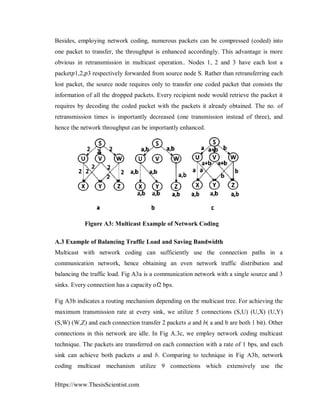


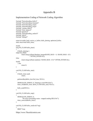
![Https://www.ThesisScientist.com
NETWORKCODING_ext *ext = NULL;
u_int8_t flags = 0;
struct in_addr dest;
long time_diff, jitter;
struct timeval now;
int msg_size = RREP_SIZE;
int i;
gettimeofday(&now, NULL);
if (optimized_hellos &&
timeval_diff(&now, &this_host.fwd_time) > ACTIVE_ROUTE_TIMEOUT) {
hello_stop();
return;
}
time_diff = timeval_diff(&now, &this_host.bcast_time);
jitter = hello_jitter();
if (time_diff >= HELLO_INTERVAL) {
for (i = 0; i < MAX_NR_INTERFACES; i++) {
if (!DEV_NR(i).enabled)
continue;
#ifdef DEBUG_HELLO
DEBUG(LOG_DEBUG, 0, "sending Hello to 255.255.255.255");
#endif
rrep = rrep_create(flags, 0, 0, DEV_NR(i).ipaddr,
this_host.seqno,
DEV_NR(i).ipaddr,
ALLOWED_HELLO_LOSS * HELLO_INTERVAL);
/* Assemble a RREP extension which contain our neighbor set... */
if (unidir_hack) {
int i;
if (ext)
ext = NETWORKCODING_EXT_NEXT(ext);
else
ext = (NETWORKCODING_ext *) ((char *) rrep + RREP_SIZE);
ext->type = RREP_HELLO_NEIGHBOR_SET_EXT;
ext->length = 0;
for (i = 0; i < RT_TABLESIZE; i++) {
list_t *pos;
list_foreach(pos, &rt_tbl.tbl[i]) {
rt_table_t *rt = (rt_table_t *) pos;
if (rt->hello_timer.used) {
#ifdef DEBUG_HELLO
DEBUG(LOG_INFO, 0,
"Adding %s to hello neighbor set ext",
ip_to_str(rt->dest_addr));
#endif](https://image.slidesharecdn.com/usnthesisnew-170510090413/85/Master-Thesis-on-Performance-Improvement-of-Underwater-Acoustic-Sensor-Network-using-Network-Coding-Algorithm-121-320.jpg)


![Https://www.ThesisScientist.com
}
int rrep_add_hello_ext(RREP * rrep, int offset, u_int32_t interval)
{
NETWORKCODING_ext *ext;
ext = (NETWORKCODING_ext *) ((char *) rrep + RREP_SIZE + offset);
ext->type = RREP_HELLO_INTERVAL_EXT;
ext->length = sizeof(interval);
memcpy(NETWORKCODING_EXT_DATA(ext), &interval, sizeof(interval));
return (offset + NETWORKCODING_EXT_SIZE(ext));
}
endif /* NS_PORT */
#ifndef NS_PORT
#define SO_RECVBUF_SIZE 256*1024
static char recv_buf[RECV_BUF_SIZE];
static char send_buf[SEND_BUF_SIZE];
extern int wait_on_reboot, hello_qual_threshold, ratelimit;
static void Networkcoding_socket_read(int fd);
static struct cmsghdr *__cmsg_nxthdr_fix(void *__ctl, size_t __size,
struct cmsghdr *__cmsg)
{
struct cmsghdr *__ptr;
__ptr = (struct cmsghdr *) (((unsigned char *) __cmsg) +
CMSG_ALIGN(__cmsg->cmsg_len));
if ((unsigned long) ((char *) (__ptr + 1) - (char *) __ctl) > __size)
return NULL;
return __ptr;
}
struct cmsghdr *cmsg_nxthdr_fix(struct msghdr *__msg, struct cmsghdr *__cmsg)
{
return __cmsg_nxthdr_fix(__msg->msg_control, __msg->msg_controllen, __cmsg);
}
#endif /* NS_PORT */
void NS_CLASS Networkcoding_socket_init()
{
#ifndef NS_PORT
struct sockaddr_in Networkcoding_addr;
struct ifreq ifr;
int i, retval = 0;
int on = 1;
int tos = IPTOS_LOWDELAY;
int bufsize = SO_RECVBUF_SIZE;](https://image.slidesharecdn.com/usnthesisnew-170510090413/85/Master-Thesis-on-Performance-Improvement-of-Underwater-Acoustic-Sensor-Network-using-Network-Coding-Algorithm-131-320.jpg)


![Https://www.ThesisScientist.com
struct in_addr src, dst;
struct hdr_cmn *ch = HDR_CMN(p);
struct hdr_ip *ih = HDR_IP(p);
hdr_Networkcodinguu *ah = HDR_NETWORKCODINGUU(p);
src.s_addr = ih->saddr();
dst.s_addr = ih->daddr();
len = ch->size() - IP_HDR_LEN;
ttl = ih->ttl();
NETWORKCODING_msg *Networkcoding_msg = (NETWORKCODING_msg *) recv_buf;
/* Only handle NETWORKCODINGUU packets */
assert(ch->ptype() == PT_NETWORKCODINGUU);
/* Only process incoming packets */
assert(ch->direction() == hdr_cmn::UP);
/* Copy message to receive buffer */
memcpy(recv_buf, ah, RECV_BUF_SIZE);
/* Deallocate packet, we have the information we need... */
Packet::free(p);
/* Ignore messages generated locally */
for (i = 0; i < MAX_NR_INTERFACES; i++)
if (this_host.devs[i].enabled &&
memcmp(&src, &this_host.devs[i].ipaddr,
sizeof(struct in_addr)) == 0)
return;
Networkcoding_socket_process_packet(Networkcoding_msg, len, src, dst, ttl, NS_IFINDEX);
}
#else
static void Networkcoding_socket_read(int fd)
{
struct in_addr src, dst;
int i, len, ttl = -1;
NETWORKCODING_msg *Networkcoding_msg;
struct dev_info *dev;
struct msghdr msgh;
struct cmsghdr *cmsg;
struct iovec iov;
char ctrlbuf[CMSG_SPACE(sizeof(int)) +
CMSG_SPACE(sizeof(struct in_pktinfo))];
struct sockaddr_in src_addr;
dst.s_addr = -1;
iov.iov_base = recv_buf;
iov.iov_len = RECV_BUF_SIZE;
msgh.msg_name = &src_addr;
msgh.msg_namelen = sizeof(src_addr);
msgh.msg_iov = &iov;
msgh.msg_iovlen = 1;
msgh.msg_control = ctrlbuf;](https://image.slidesharecdn.com/usnthesisnew-170510090413/85/Master-Thesis-on-Performance-Improvement-of-Underwater-Acoustic-Sensor-Network-using-Network-Coding-Algorithm-135-320.jpg)
![Https://www.ThesisScientist.com
msgh.msg_controllen = sizeof(ctrlbuf);
len = recvmsg(fd, &msgh, 0);
if (len < 0) {
alog(LOG_WARNING, 0, __FUNCTION__, "receive ERROR len=%d!", len);
return;
}
src.s_addr = src_addr.sin_addr.s_addr;
/* Get the ttl and destination address from the control message */
for (cmsg = CMSG_FIRSTHDR(&msgh); cmsg != NULL;
cmsg = CMSG_NXTHDR_FIX(&msgh, cmsg)) {
if (cmsg->cmsg_level == SOL_IP) {
switch (cmsg->cmsg_type) {
case IP_TTL:
ttl = *(CMSG_DATA(cmsg));
break;
case IP_PKTINFO:
{
struct in_pktinfo *pi = (struct in_pktinfo *)CMSG_DATA(cmsg);
dst.s_addr = pi->ipi_addr.s_addr;
}
}
}
}
if (ttl < 0) {
DEBUG(LOG_DEBUG, 0, "No TTL, packet ignored!");
return;
}
/* Ignore messages generated locally */
for (i = 0; i < MAX_NR_INTERFACES; i++)
if (this_host.devs[i].enabled &&
memcmp(&src, &this_host.devs[i].ipaddr,
sizeof(struct in_addr)) == 0)
return;
Networkcoding_msg = (NETWORKCODING_msg *) recv_buf;
dev = devfromsock(fd);
if (!dev) {
DEBUG(LOG_ERR, 0, "Could not get device info!n");
return;
}
Networkcoding_socket_process_packet(Networkcoding_msg, len, src, dst, ttl, dev->ifindex);
}
#endif /* NS_PORT */
void NS_CLASS Networkcoding_socket_send(NETWORKCODING_msg * Networkcoding_msg, struct
in_addr dst,
int len, u_int8_t ttl, struct dev_info *dev)](https://image.slidesharecdn.com/usnthesisnew-170510090413/85/Master-Thesis-on-Performance-Improvement-of-Underwater-Acoustic-Sensor-Network-using-Network-Coding-Algorithm-136-320.jpg)

![Https://www.ThesisScientist.com
switch (Networkcoding_msg->type) {
case NETWORKCODING_RREQ:
if (num_rreq == (RREQ_RATELIMIT - 1)) {
if (timeval_diff(&now, &rreq_ratel[0]) < 1000) {
DEBUG(LOG_DEBUG, 0, "RATELIMIT: Dropping RREQ %ld ms",
timeval_diff(&now, &rreq_ratel[0]));
#ifdef NS_PORT
Packet::free(p);
#endif
return;
} else {
memmove(rreq_ratel, &rreq_ratel[1],
sizeof(struct timeval) * (num_rreq - 1));
memcpy(&rreq_ratel[num_rreq - 1], &now,
sizeof(struct timeval));
}
} else {
memcpy(&rreq_ratel[num_rreq], &now, sizeof(struct timeval));
num_rreq++;
}
break;
case NETWORKCODING_RERR:
if (num_rerr == (RERR_RATELIMIT - 1)) {
if (timeval_diff(&now, &rerr_ratel[0]) < 1000) {
DEBUG(LOG_DEBUG, 0, "RATELIMIT: Dropping RERR %ld ms",
timeval_diff(&now, &rerr_ratel[0]));
#ifdef NS_PORT
Packet::free(p);
#endif
return;
} else {
memmove(rerr_ratel, &rerr_ratel[1],
sizeof(struct timeval) * (num_rerr - 1));
memcpy(&rerr_ratel[num_rerr - 1], &now,
sizeof(struct timeval));
}
} else {
memcpy(&rerr_ratel[num_rerr], &now, sizeof(struct timeval));
num_rerr++;
}
break;
}
}
if (dst.s_addr == NETWORKCODING_BROADCAST) {
gettimeofday(&this_host.bcast_time, NULL);
#ifdef NS_PORT
ch->addr_type() = NS_AF_NONE;
sendPacket(p, dst, 0.0);
#else
retval = sendto(dev->sock, send_buf, len, 0,](https://image.slidesharecdn.com/usnthesisnew-170510090413/85/Master-Thesis-on-Performance-Improvement-of-Underwater-Acoustic-Sensor-Network-using-Network-Coding-Algorithm-138-320.jpg)

![Https://www.ThesisScientist.com
#ifndef NS_PORT
int i;
for (i = 0; i < MAX_NR_INTERFACES; i++) {
if (!DEV_NR(i).enabled)
continue;
close(DEV_NR(i).sock);
}
#endif /* NS_PORT */
}
oid NS_CLASS rt_table_init()
{
int i;
rt_tbl.num_entries = 0;
rt_tbl.num_active = 0;
/* We do a for loop here... NS does not like us to use memset() */
for (i = 0; i < RT_TABLESIZE; i++) {
INIT_LIST_HEAD(&rt_tbl.tbl[i]);
}
}
void NS_CLASS rt_table_destroy()
{
int i;
list_t *tmp = NULL, *pos = NULL;
for (i = 0; i < RT_TABLESIZE; i++) {
list_foreach_safe(pos, tmp, &rt_tbl.tbl[i]) {
rt_table_t *rt = (rt_table_t *) pos;
rt_table_delete(rt);
}
}
}
/* Calculate a hash value and table index given a key... */
unsigned int hashing(struct in_addr *addr, hash_value * hash)
{
/* *hash = (*addr & 0x7fffffff); */
*hash = (hash_value) addr->s_addr;
return (*hash & RT_TABLEMASK);
}
rt_table_t *NS_CLASS rt_table_insert(struct in_addr dest_addr,
struct in_addr next,
u_int8_t hops, u_int32_t seqno,
u_int32_t life, u_int8_t state,
u_int16_t flags, unsigned int ifindex)
{
hash_value hash;
unsigned int index;
list_t *pos;](https://image.slidesharecdn.com/usnthesisnew-170510090413/85/Master-Thesis-on-Performance-Improvement-of-Underwater-Acoustic-Sensor-Network-using-Network-Coding-Algorithm-140-320.jpg)
![Https://www.ThesisScientist.com
rt_table_t *rt;
struct in_addr nm;
nm.s_addr = 0;
/* Calculate hash key */
index = hashing(&dest_addr, &hash);
/* Check if we already have an entry for dest_addr */
list_foreach(pos, &rt_tbl.tbl[index]) {
rt = (rt_table_t *) pos;
if (memcmp(&rt->dest_addr, &dest_addr, sizeof(struct in_addr))
== 0) {
DEBUG(LOG_INFO, 0, "%s already exist in routing table!",
ip_to_str(dest_addr));
return NULL;
}
}
if ((rt = (rt_table_t *) malloc(sizeof(rt_table_t))) == NULL) {
fprintf(stderr, "Malloc failed!n");
exit(-1);
}
memset(rt, 0, sizeof(rt_table_t));
rt->dest_addr = dest_addr;
rt->next_hop = next;
rt->dest_seqno = seqno;
rt->flags = flags;
rt->hcnt = hops;
rt->ifindex = ifindex;
rt->hash = hash;
rt->state = state;
timer_init(&rt->rt_timer, &NS_CLASS route_expire_timeout, rt);
timer_init(&rt->ack_timer, &NS_CLASS rrep_ack_timeout, rt);
timer_init(&rt->hello_timer, &NS_CLASS hello_timeout, rt);
rt->last_hello_time.tv_sec = 0;
rt->last_hello_time.tv_usec = 0;
rt->hello_cnt = 0;
rt->nprec = 0;
INIT_LIST_HEAD(&rt->precursors);
/* Insert first in bucket... */
rt_tbl.num_entries++;
DEBUG(LOG_INFO, 0, "Inserting %s (bucket %d) next hop %s",
ip_to_str(dest_addr), index, ip_to_str(next));
list_add(&rt_tbl.tbl[index], &rt->l);](https://image.slidesharecdn.com/usnthesisnew-170510090413/85/Master-Thesis-on-Performance-Improvement-of-Underwater-Acoustic-Sensor-Network-using-Network-Coding-Algorithm-141-320.jpg)


![Https://www.ThesisScientist.com
next_hop_rt = rt_table_find(rev_rt->next_hop);
if (next_hop_rt && next_hop_rt->state == VALID && rev_rt &&
next_hop_rt->dest_addr.s_addr != rev_rt->dest_addr.s_addr &&
(llfeedback || rev_rt->hello_timer.used))
rt_table_update_timeout(next_hop_rt,
ACTIVE_ROUTE_TIMEOUT);
rt_table_t *NS_CLASS rt_table_find(struct in_addr dest_addr)
{
hash_value hash;
unsigned int index;
list_t *pos;
if (rt_tbl.num_entries == 0)
return NULL;
/* Calculate index */
index = hashing(&dest_addr, &hash);
/* Handle collisions: */
list_foreach(pos, &rt_tbl.tbl[index]) {
rt_table_t *rt = (rt_table_t *) pos;
if (rt->hash != hash)
continue;
if (memcmp(&dest_addr, &rt->dest_addr, sizeof(struct in_addr))
== 0)
return rt;
}
return NULL;
}
rt_table_t *NS_CLASS rt_table_find_gateway()
{
rt_table_t *gw = NULL;
int i;
for (i = 0; i < RT_TABLESIZE; i++) {
list_t *pos;
list_foreach(pos, &rt_tbl.tbl[i]) {
rt_table_t *rt = (rt_table_t *) pos;
if (rt->flags & RT_GATEWAY && rt->state == VALID) {
if (!gw || rt->hcnt < gw->hcnt)
gw = rt;
}
}
}
return gw;
}](https://image.slidesharecdn.com/usnthesisnew-170510090413/85/Master-Thesis-on-Performance-Improvement-of-Underwater-Acoustic-Sensor-Network-using-Network-Coding-Algorithm-145-320.jpg)
![Https://www.ThesisScientist.com
#ifdef CONFIG_GATEWAY
int NS_CLASS rt_table_update_inet_rt(rt_table_t * gw, u_int32_t life)
{
int n = 0;
int i;
if (!gw)
return -1;
for (i = 0; i < RT_TABLESIZE; i++) {
list_t *pos;
list_foreach(pos, &rt_tbl.tbl[i]) {
rt_table_t *rt = (rt_table_t *) pos;
if (rt->flags & RT_INET_DEST && rt->state == VALID) {
rt_table_update(rt, gw->dest_addr, gw->hcnt, 0,
life, VALID, rt->flags);
n++;
}
}
}
return n;
}
#endif /* CONFIG_GATEWAY_DISABLED */
/* Route expiry and Deletion. */
int NS_CLASS rt_table_invalidate(rt_table_t * rt)
{
struct timeval now;
gettimeofday(&now, NULL);
if (rt == NULL)
return -1;
/* If the route is already invalidated, do nothing... */
if (rt->state == INVALID) {
DEBUG(LOG_DEBUG, 0, "Route %s already invalidated!!!",
ip_to_str(rt->dest_addr));
return -1;
}
if (rt->hello_timer.used) {
DEBUG(LOG_DEBUG, 0, "last HELLO: %ld",
timeval_diff(&now, &rt->last_hello_time));
}
/* Remove any pending, but now obsolete timers. */
timer_remove(&rt->rt_timer);
timer_remove(&rt->hello_timer);
timer_remove(&rt->ack_timer);
/* Mark the route as invalid */
rt->state = INVALID;
rt_tbl.num_active--;](https://image.slidesharecdn.com/usnthesisnew-170510090413/85/Master-Thesis-on-Performance-Improvement-of-Underwater-Acoustic-Sensor-Network-using-Network-Coding-Algorithm-146-320.jpg)
![Https://www.ThesisScientist.com
rt->hello_cnt = 0;
/* When the lifetime of a route entry expires, increase the sequence
number for that entry. */
seqno_incr(rt->dest_seqno);
rt->last_hello_time.tv_sec = 0;
rt->last_hello_time.tv_usec = 0;
#ifndef NS_PORT
nl_send_del_route_msg(rt->dest_addr, rt->next_hop, rt->hcnt);
#endif
#ifdef CONFIG_GATEWAY
if (rt->flags & RT_GATEWAY) {
int i;
rt_table_t *gw = rt_table_find_gateway();
for (i = 0; i < RT_TABLESIZE; i++) {
list_t *pos;
list_foreach(pos, &rt_tbl.tbl[i]) {
rt_table_t *rt2 = (rt_table_t *) pos;
if (rt2->state == VALID
&& (rt2->flags & RT_INET_DEST)
&& (rt2->next_hop.s_addr ==
rt->dest_addr.s_addr)) {
if (0) {
DEBUG(LOG_DEBUG, 0,
"Invalidated GW %s but found new GW %s for
%s",
ip_to_str(rt->dest_addr),
ip_to_str(gw->dest_addr),
ip_to_str(rt2->
dest_addr));
rt_table_update(rt2,
gw->dest_addr,
gw->hcnt, 0,
timeval_diff
(&rt->rt_timer.
timeout, &now),
VALID,
rt2->flags);
} else {
rt_table_invalidate(rt2);
precursor_list_destroy(rt2);
}
}
}
}
}
#endif](https://image.slidesharecdn.com/usnthesisnew-170510090413/85/Master-Thesis-on-Performance-Improvement-of-Underwater-Acoustic-Sensor-Network-using-Network-Coding-Algorithm-147-320.jpg)


More Related Content
What's hot (20)
Similar to Master Thesis on Performance Improvement of Underwater Acoustic Sensor Network using Network Coding Algorithm (20)


More from Thesis Scientist Private Limited (20)


Recently uploaded (20)


![MODULE 03 - CLOUD COMPUTING- [BIS 613D] 2022 scheme.pptx](https://cdn.slidesharecdn.com/ss_thumbnails/module03-cloudcomputing-250506150212-e107fd7e-thumbnail.jpg?width=560&fit=bounds)
![COMPUTER GRAPHICS AND VISUALIZATION :MODULE-02 notes [BCG402-CG&V].pdf](https://cdn.slidesharecdn.com/ss_thumbnails/module-02notesbcg402-cgv-250506151048-aef09ce3-thumbnail.jpg?width=560&fit=bounds)
Master Thesis on Performance Improvement of Underwater Acoustic Sensor Network using Network Coding Algorithm
- 1. For more Https://www.ThesisScientist.com 42 Performance Improvement of Underwater Acoustic Sensor Network using Network Coding Algorithm A Synopsis Submitted in the Partial Fulfilment of The Award of the Degree of MASTER OF TECHNOLOGY IN COMPUTER SCIENCE AND ENGINEERING Under Guidance of: Submitted By: Name of Internal Guide Name of Students (Designation) Roll No
- 2. For more Https://www.ThesisScientist.com 43 CONTENTS Candidate Declaration Certificate Acknowledgement Abstract Contents Abbreviations I ii iii iv v Chapter 1 Introduction 1.1. Overview………………………………………………………………… 1.2. 1 .Network Coding Algorithm…………………………………………... 1.2.2. Topologies……………………………………………………………... 1.2.3.Routing Protocol with Network Coding ……………………………… 1.2.3.1 Coding Based Routing Protocoals (Intra Flow Coding)………… 1.2.3.2. Coding Aware Routing Protocoals (Inter Flow Coding)………… 1.2.3.3Network Coding in MAC and TCP……………………………….. 1.2.4.Underwater Networks………………………………………………… 1.2.5.Benefits of Network Coding………………………………………….. 1.3. Motivation and Objectives………………………………………………. 1.4. Methodologies and Approaches…………………………………………. 1.5.Contributions 1.6 Layout of Thesis Chapter 2 Literature Review…………………………………………………… 2.1.Literature Review ………………………………………………………... Chapter 3 Background Study…………………………………………………... 3.1.Underwater Acoustic Sensor Networks Communication Architecture…... 3.2.Challenges……………………………………………………………….. 3.3 Assumptions……………………………………………………………… 3.4 Target Scenrio……………………………………………………………. 1 1 2 3 5 5 5 6 7 8 9 10 12 12 14 14 21 21 23 24
- 3. For more Https://www.ThesisScientist.com 44 3.4.1. Line-up Network……………………………………………………… 3.4.2.Meshed Network……………………………………………………….. 3.5..Technical Criteria………………………………………………………... 3.6.Design Consideration……………………………………………………. Chapter 4 Proposed Work…………………………………………………… 4.1. Network Layout and Operation…………………………………………. 4.2. Network Coding at a Node……………………………………………... 4.2.1. Encoding Implementation………………………………………... 4.2.2. Decoding………………………………………………………… 4.3. Topologies for Network Coding ……………………………………….. 4.4. OPNET Models ……………………………………………………….. 4.4.1. Packet for Network Coding………………………………………. 4.4.2.Node Model and Process Model…………………………………... 4.4.3. Pipeline Stages……………………………………………………. 4.5. Assumption…………………………………………………………….. Chapter 5 Result ……………………………………………………………… 5.1 The opnet simulation and performance evaluation……………………… 5.2 Small network ………………………………………………………….. 5.2.1 Butterfly topology………………………………………………….. 5.2.1.1. Throughput…………………………………………………. 5.2.1.2. ETE Delay………………………………………………… 5.2.1.3 .PDR……………………………………………………… 5.2.1.4 .Mean Queue Size of the Coding Node…………………… 5.2.2Multi Relay Topology……………………………………………… 5.2.2.1.Throughput………………………………………………… 5.2.2.2. ETE Delay………………………………………………… 5.2.2.3. PDR………………………………………………………. 5.2.2.4. Mean Queue Size of the Coding Node……………………. 25 25 26 27 29 31 31 32 33 34 36 37 37 38 40 41 42 42 43 43 44
- 4. For more Https://www.ThesisScientist.com 45 5.2.3. Performance Tradeoff and comparision of the two topologies…… 5.3. Big Network…………………………………………………………….. 5.3.1. Performance Evaluation…………………………………………… 5.3.1.1. Throughput……………………………………………..... 5.3.1.2.ETE Delay………………………………………………… 5.3.1.3. PDR ……………………………………………………… 5.3.1.4. Mean Queue Size…………………………………………. 5.3.2. Performance Tradeoff……………………………………………… 5.4.Concluding Remarks …………………………………………………… Chapter 6 Conclusions………………………………………………………… 6.1.Conclusion………………………………………………………………… 6.2Furture Work ……………………………………………………………… References………………………………………………...................................... Appendix A:……………………………………………………………………. A.1: Example of Achieving Maximum Flow in a Network…………………. A.2: Example of Improving Throughput…………………………………… A.3: Example of Balancing Traffic Load and Saving Bandwidth………….. Appendix B:………………………………………… 45 46 47 48 49 51 51 52 52 52 55 55 57 58 59 59 59 61 61 62 63 67 67 69 70 71
- 5. For more Https://www.ThesisScientist.com 46 LIST OF ABBREVIATIONS UAV Unmanned aerial vehicle UAANET Unmanned Aeronautical Ad-hoc Network AANET Aircraft Ad-hoc Network AODV Ad hoc On Demand Distance Routing Vector CBLADSR Cluster-Based Location - Aided Dynamic Source Routing DES Data Encryption Standard DREAM Distance Routing Effect Algorithm for Mobility DSR Dynamic Source Routing EGR Energy Aware Geographic Routing FANET Flying Ad-hoc Network FTP File Transfer Protocol GPS Global Positioning System GPSR Greedy Perimeter Stateless Routing IDE Integrated Development Environment IEEE Institute of Electrical and Electronics Engineering IMU Greedy Geographic Forwarding LAN Local Area Network LAR Location-aided Routing MAC Medium access control
- 6. For more Https://www.ThesisScientist.com 47 MANET Mobile Ad-hoc Network MDD Model Driven Development NS2 Network Simulator 2 OLSR Optimized Link State Routing OPNET Optimized Network Engineering Tool RGR Reactive-Greedy-Reactive RREP Route Response RREQ Route Request SCF Store-Convey Forward SRCM Semi-Random Circular Development VANET Vehicular Ad-hoc Network XML Extensible Markup Language
- 7. For more Https://www.ThesisScientist.com 48 CHAPTER 1 INTRODUCTION 1.1 Overview With the advancement in acoustic modem technology that enabled high-rate reliable communications, current research concentrates on communication between several remote instruments within a network atmosphere [2]. Research on underwater networking has become an attractive, interesting and challenging area today because of its support to the applications i.e. pollution monitoring, oceanographic data collection, disaster prevention, offshore exploration and assisted navigation [1]. We can describe underwater acoustic networking as the enabling technique for these applications. Underwater acoustic (UWA) networks are normally configured by acoustically linking autonomous underwater vehicles, bottom sensors and a surface station, which offers a connection to an on-shore control centre [1]. In conventional operation, network nodes utilize the store-forward techniques, and network transmission performance is constrained by the capacity of some bottleneck connections. With respect to the Maximum Flow Minimum Cut theory, the transmission rate between the receivers and transmitters cannot increase the maximum network flow. So the conventional multipath routing often cannot arrive the upper bound of the maximum flow. Comes network coding which breaks the conventional way of data transmission [4]. With network coding, the intermediary nodes no longer just send packets only. They are permitted to process the packets, and integrate two or many income packets into one or many output packets for transmission. This builds it possible to utilize less network bandwidth to forward the same amount of information. At last, the actual packets can be retrieved in their destinations [3]. Network coding technology is a discovery in network communication area [4]. It has been broadly studied in current years because of its powerful advantages of enhancing the throughput of the network, decreasing transmission times, increasing end-to-end
- 8. For more Https://www.ThesisScientist.com 49 performance and offering a high degree of network flexibility. It can also save bandwidth, balance traffic load and enhance the network security. Routing Protocols and algorithms depending on network coding are applied to wireless or wired communication. With its capability of enhancing network performance, it could also be used to ad-hoc networks, wireless multi-hop networks, wireless sensor networks and particularly underwater sensor networks. Fig 1.1:Underwater Sensor Architecture UAN (Underwater Acoustic Network) is an application of wireless networks which utilizes acoustic as the data transmission medium in underwater atmosphere [5]. As compared to terrestrial radio channel, underwater channel has several natural loss factors i.e. Doppler shift, ocean noise, multipath impact and transmission fading. These unique UAN features cause high bit rate, long propagation delay, restricted bandwidth and restricted energy, and build it hard to obtain efficient data transmission [4]. 1.2.1 Network Coding Algorithms
- 9. For more Https://www.ThesisScientist.com 50 Network coding idea is first introduced by R. Ahlswede et al. From the information flow point of view, they showed that in a multicast network with a single source and many sinks, the maximum network throughput as determined by the max-flow min-cut theory can be obtained by utilizing a simple network coding; the bandwidth can be saved also [4, 7]. The basic feature of network coding is the optimal processing of different transmission data. This should be directly reflected by the different design of coding techniques, and the code structure is the main concern. So the actual research in network coding primarily concentrates on the coding algorithms, the enhancement of performance brought by a coding technique and the complexity degree of the coding algorithm. The code structure algorithm design should ensure the targeted nodes can decode the actual packets after they obtained a specific amount of coded packets. During this time, the coding complexity should be decreased. The coding structure algorithms studied so far can be classified into three categories: algebraic coding, linear coding and random coding [7]. A construction of linear coding was introduced for its practicability and simplicity. A multicast network is developed and it is shown that the max-flow bound can be arrived through a linear coding multicast. Linear coding also involves the polynomial time algorithm. But perhaps the easiest form is the coding based on the XOR operation i.e., just perform the Exclusive-OR operation on the bits of two packets. There are several XOR-based protocols i.e. ROCX (Routing with Opportunistically Coded eXchanges) and COPE. In the introduced algebraic framework-based coding mechanism a polynomial algorithm was utilized to solve network issues and an algebraic tool was offered to the network coding research. A randomized network coding for numerous source multicast networks was proposed in where the success possibility [6, 7]. 1.2.2 Topologies The network topology is a necessary issue we require to assume when studying network coding. One would observe that a regular configuration often provides network coding. We shall classify and summarize below some general topologies utilized in the network coding research [12].
- 10. For more Https://www.ThesisScientist.com 51 1) Linear Topology In the linear topology, each node has one upstream node and one downstream node to transmit or obtain data. A routing technique depending on network coding has been introduced for 6 nodes. Another study only utilizes three node but with a queuing model in the middle for comparison of the NC model and non-NC model. A simple three node wireless linear topology can also be transformed to a butterfly configuration. In the introduced PCMRDT (Practical Coding based Multi-hop Reliable Data Transfer) protocol, simulations of a multi-hop linear topology were carried out to measure performance of delay and the no. of packets transferred per data packet [18]. 2) X topology In this topology, there are 5 nodes occupying the centre and ends of the letter X. Studies have indicated that network coding can enhance the coding gain in the X topology. A double decoding mechanism was introduced to enhance the network throughput in both the slightly lousy and loss-free networks [18]. 3) Butterfly Topology The butterfly topology may be the most widely utilized topology in the network coding research. The network coding idea was first introduced utilizing the multicast butterfly topology. The same model was also employed to propose random network coding and linear network coding. A queuing analysis of the butterfly network was carried out, and the NC performance was compared with classic routing. A theoretical coding model was studied for coding-aware-based routing on the butterfly network. The performance of end-to-end delay of butterfly topology was inquired, and it was concluded that network coding can have a big effect on delay performance. Another research utilized network coding to a altered underwater network and experiment with practical underwater device [18]. 4) Diamond Topology The diamond topology is often utilized to emphasize the high error recovery features of random network coding. The advantage of effective error recovery rate was depicted in and the coding technique was applied to underwater networks employing VBF (Vector
- 11. For more Https://www.ThesisScientist.com 52 Based Forwarding) routing. The diamond topology was also utilized and enforced in a real UASN (Underwater Acoustic Sensor Network) model [2] 5) Random Topology Additionally, the regular topologies, some researchers have used network coding to random topologies. A algorithms suite for network CLONE (Coding with LOss awareNEss) operation was introduced by proposing enough redundancy in local network coding operations. Simulation is the primary tool for performance measurement. One research measured the throughput performance of single-path routing and coding-aware multipath routing depending on a 15-node random wireless configuration. Others also examined the effect of network coding on the MAC (Medium Access Control) protocol depending on the CSMA/CA (Carrier Sense Multiple Access/Collision Avoidance) scheme and carried out simulations on a configuration with 50 randomly-distributed nodes[17.] 1.2.3 Routing Protocols with Network Coding Coding-based routing protocols are practical implementation of network coding. Researchers have noted that the integration of localized NC and route selection would further enhance the wireless networks performance. Much research has-been performed to integrate routing and coding in both practical analysis and theoretical system design. There are two general classes: coding-aware routing and coding-based routing. The difference between themes whether the coded packets come from the same information flow. 1.2.3.1Coding-Based Routing Protocols (Intra-Flow Coding) Coding-based routing is also called intra-flow network coding where routers can only code packets from the same flow. In the coding-based protocol with MORE (MAC- independent Opportunistic Routing & Encoding) the source divides the file into batches of K packets. Before sending, the source combines the K packets into a linear combination randomly and floods the coded packets. MORE is also been checked in a 20-node wireless network, and compared with the conventional best path routing known
- 12. For more Https://www.ThesisScientist.com 53 as ExOR, which is an Opportunistic Multi-Hop Routing for Wireless Networks. The result indicates that MORE can dramatically enhance the network throughput. One MORE issue is that a sending node does not know how much coded packets they should send. So a destination may obtain several redundancy packets which do not consist any new information and has to loss all of them. The useless packets are a waste of the transmission bandwidth. For solving this issue, a novel NC-based protocol CCACK (Cumulative Coded Acknowledgment) was introduced. This novel NC-based protocol enables nodes to acknowledge the obtained coded packets of their upstream nodes. This would void the unessential transmission accordingly for saving the bandwidth. Performance measurements results indicate that CCACK importantly enhances throughput as compared to MORE. Finally, the OMNC (Optimized Multipath Network Coding) exploits rate control technique to assign the optimal encoding and broadcast rate to all nodes, and accordingly to control the network congestion. 1.2.3.2 Coding-Aware Routing Protocols (Inter-Flow Coding) Inter-flow coding enables the intermediary nodes to code packets from several flows. COPE is the first protocol to utilize network coding in wireless mesh networks. The protocol has used the network coding theory on a practical uni-cast network. Acceding layer is embedded between the MAC layer and the IP layer. Every node can overhear its neighboring packets, record any packets it obtained for a specified period and flood packets reception report it has to its neighbors. The router will XOR many packets together and transfers the coded packets in a single transmission. Performance measurement of COPE on a 20–node wireless network indicates that network throughput is improved a lot. Although COPE can determine coding opportunities on the chosen routing path, many other powerful coding opportunities are usually ignored. This is because the routing and coding in COPE are not dependent. It looks for coding opportunities passively however it cannot change the route selection. To obtain a further gain, a routing protocol ROCX (Routing with Opportunistically Coded eXchanges) was introduced. A metric known as the ECX (Expected Coding Transmission)is utilized to catch the expected no. of coded transmissions required for a successful interchange of packets between two nodes through an intermediary node. ROCX analyses the network
- 13. For more Https://www.ThesisScientist.com 54 coding opportunities with a linear optimization algorithm. The evaluation results indicated that ROCX can further decrease the no. of transmissions in COPE. Since this protocol needs every intermediary node to have a very high calculation capacity. Integrating network coding with routing selection within the network can generate more coding opportunities initiatively. Examples are the Rate RCR (Adaptive Coding Aware Routing) and CAMR(Coding Aware Multipath Routing). 1.2.3.3 Network Coding in MAC and TCP In addition to integrating network coding with routing protocols, some researchers also begin to implement network coding in other protocol layers i.e. the TCP (Transmission Control Protocol) layer and the MAC layer. BEND is a practical MAC layer coding technique in multi-hop networks which is also the first exploration of the broadcast behavior of wireless channels In protocols i.e. COPE, network coding can only be done at joint nodes within the routing path. BEND permits all neighbors of a node to overhear the packet transmission and send the packets by only one of these neighbors. dSeveral topologies ddwere utilized to measure BEND and to compare IEEE 802.11 with COPE. The results indicate that BEND can obtain a higher throughput and coding ratio. For making network coding compatible with the sliding window and retransmission schemes of TCP, a new mechanism is introduced to incorporate network coding into TCP layer In their mechanism, the source transfer a random but linear combinations of packets in the sliding window. Instead of forwarding an ACK for every packet decoded successfully, the sink will forward an ACK to show the no. of coded packets already obtained. An adaptive W mechanism was introduced to adaptively control the packets waiting time recorded in a buffer. By utilizing this technique, a tradeoff between TCP throughput and packet over head has been obtained. 1.2.4 Underwater Networks Underwater sensor networks are different from terrestrial networks in various different aspects. One of the differences is the communication media. Unlike the terrestrial networks utilizing electromagnetic waves to interact, underwater networks often utilize
- 14. For more Https://www.ThesisScientist.com 55 acoustic wave Currently, the applications and researches on underwater network coding are still at their stage of growth however the network coding technology is not as developed as air wireless communications [22]. We only discovered a handful of concerned papers. Network coding technique depending on VBF (Vector Based Forwarding) routing for USN has been introduced. Simulations indicated that multipath forwarding with network coding mechanism is more effective for error recovery as compared to single-path and even multiple-path forwarding without the use of network coding. Several routing techniques with network coding have been compared for providing an underwater acoustic channel model. The numerical results indicate that network coding technique has a better performance of transmission delay in the situation of high traffic loads. A novel mechanism of network coding utilizing implicit acknowledgement is also introduced to reduce nodes power consumptions. Network coding has also been used to a 2-D “cluster string topology”. The results indicate that network coding has the benefits in good energy consumption and high error recovery. A guideline and parameter setting in network coding is also offered. As an extension of the work of, the network coding algorithm is employed to a real underwater sensor network utilizing both software and hardware. The results showed that network coding enhanced the packet delivery ratio and throughput in underwater sensor network. Network coding was also carried out in a practical underwater device in shallow water with low data rates (inter-transmission time of 2s to 20s). The performances of an altered underwater butterfly network are measured. The experiment results are offered and examined. Additionally, the stationary two-dimensional underwater networks three-dimensional networks with acoustic wireless nodes are continuously utilized to determine ocean phenomena which the two dimensional network may not be capable to realize in an adequate way. In three-dimensional underwater networks, sensor nodes float at different depth levels for observing a provided phenomenon. Furthermore, the underwater channel is rather different from the terrestrial channel. A review was carried out on the available network technology and its suitability to underwater acoustic channels [21].
- 15. For more Https://www.ThesisScientist.com 56 An integration of interference avoidance and network coding technique in underwater atmosphere was investigated. Performances have been measured and compared with CDMA/CA scheme. The results indicate NC is more efficient and consumed less energy. In the work surveyed above, often only one or two network performances aspects are studied. There was no comprehensive measurement of network coding and the discussion of their tradeoff. 1.2.5 Benefits of Network Coding We can briefly explain below some of the generally claimed advantages of network coding in the papers we survey. Appendix A also surveys some papers that have offered arguments/proofs/examples to these different claims [18]. 1) Achieving maximum flow: It is aware that the theoretically maximum flow of an interaction network often cannot be obtained because of the availability of bottleneck connections in the network. With network coding, the traffic flow going through the bottleneck connection can be increased without having to increase the bandwidth (data flow rate) of the physical connection. Thus, the maximum flow of the network can be obtained [12]. 2) Improving throughput: The significance of this advantage is basis to network coding. Utilizing network coding, packets can be coded in one packet for transmission and the throughput is enhanced consequently. Observe that throughput is not only enhanced as a consequence of (1); it can also be incremented in other scenario because of network coding. For instance, the actual packets can be recovered even a small no. of packets are missing. Another instance in SectionA2 (in Appendix A) is also offered to show how enhanced throughput can be obtained. 3) Balancing traffic flow and saving bandwidth: Multicasting with network coding can sufficiently use the connection paths in a communication network, hence obtaining an even traffic network distribution and balancing the traffic load. 4) Improving reliability Higher reliability is the most obliging advantage of network coding particularly in mobile and/or lousy networks. Utilizing network coding, many original packets that are linearly independent of each other can be coded together to
- 16. For more Https://www.ThesisScientist.com 57 make a group of new coded packets. The recipient is capable to decode the real packets so long as an enough no. of encoded packets are achieved. The loss of a small no. of packets does not need retransmissions. The results indicate the network coding technique can decrease the times of packet retransmission in comparison of other mechanism. 5) Enhancing security. Another network performance would be enhanced by network coding security. The coding feature improves the complications of cracking information from the network. However a node can decode the packets only if it obtained a sufficient no. of coded packets, an eavesdropper is not capable to receive the helpful information even through it can overhear one or many coded packets. A wiretap model utilizing linear network coding was introduced where wire tappers cannot obtain the transferred information even if they are permitted to access the transmission channels. 1.3 Motivation and Objectives However Allseed et al. introduced the network coding concept in year 2000, it has been studied by several researchers in various aspects. From our literature review, we observed that the network coding performance can change with different network configurations. Selecting an appropriate topology and suitable coding nodes can build a better usage of network coding. Furthermore, most of the papers only measure only one or two network performance aspects. It would be required to have a comprehensive measurement of the networks on each mainly promised advantages of network coding, and to view if these advantages can be all obtained in the same configuration and situations. If not, what tradeoffs are in the network coding implementation to communication networks. Our literature survey also indicate that the general design objectives of underwater networks are increasing throughput among nodes, educing energy consumption, saving bandwidth and enhancing network reliability. However these seem to be the benefits of network coding also, we would like to apply network to underwater networks to look if the underwater networks performance can be enhanced [17]. The ocean is a volatile and complex atmosphere where the signal can attenuate because of diffusion loss and energy absorption during its transmission. Thus, the channel model
- 17. For more Https://www.ThesisScientist.com 58 is quite different from terrestrial channel models. We would like to set up an underwater channel model in RIVERBED Simulator for our simulation and future usage. As a basic goal of this thesis in view of the above discussion, we would like to verify the promised advantages of network coding. Particularly, we would like 1) To have a more comprehensive and systematic evaluation of network coding on some selected configurations. 2) To compare data network communication without and with network coding in terms of their performances and study the trade offs in these performances [18]. 3) To measure the performance of a wireless underwater acoustic network utilizing network coding to view if the same advantages can be obtained. 1.4 Methodologies and Approaches For achieving our goals, we require to first understand the operation descriptions of network coding so that we can integrate them into our network queuing model and measure the performance appropriately. Through the literature survey, we hope to get the knowledge and operation descriptions related to different regions involving the routing protocols with network coding, the coding algorithms, and the network coding application to multi-hop network, wireless sensor network and underwater acoustic networks. At first, we shall utilize static configurations in our network coding study because we can select by inspection which intermediary nodes in the network should perform the coding operation. We shall assume some regular configurations in this thesis and realize their network performances [18]. However there can be several possible configurations, we would be selective to take a few famous ones in the literature. We initiate with the butterfly configuration and the multi-relay topology which are small networks of continuous configurations, We have not selected the single node nor the three-node linear network utilized by several researchers because they are a subset of the two selected candidates that have more characteristics for us to study and to compare with networks without coding for understanding the tradeoffs. We shall study the queuing nature of a coding node and the
- 18. For more Https://www.ThesisScientist.com 59 network performance i.e. end to end delay and network throughout. Then we select some big regular configurations for seeing and understanding how network performance would change when utilizing different configurations and/or bigger networks [12]. The big and small networks we shall study all have two-dimensional configurations that can detect applications in land-based networks. We shall also explore our study to a three-dimensional network by studying an USN. Here, we have the issue to understand first the underwater physical atmosphere for acoustic propagation and thus the effect to data communication. This would also permit us to detect the suitable channel model which we shall integrate into our underwater topology for the study and network coding analysis. However a queuing analysis includes much time in mathematics for the time limit of this study, we have resorted to simulation. Of all the simulation languages existed in the research world, I have selected RIVERBED (Optimized Network Engineering Tools) [OPNE14] to be our simulation simulator because that its hierarchical modeling technique builds it simple to utilize and our research group already has a lot of expertness about exploiting RIVERBED. RIVERBED has a sophisticated workstation-based atmosphere for the modeling and simulation of communication systems, networks and protocols for verifying the described operations of some protocol and to examine their performance. On the other side, it is comparatively easy to utilize once its design ideas are understood. RIVERBED contains four major components: Project Editor, Node Editor, Process Editor and Packet Editor [OPNE14]. Project Editor is utilized to make the network topology and offer the basic analysis abilities and simulation. With the Node Editor, we can make a node with several objects and describe several interfaces. The Process Editor contains various states linked with transition situations; the process behavior is mentioned utilizing C/C++ language. The Packet Editor is utilized to describe the packet internal structure which can have various different formats and fields. The debugging tool is another very helpful characteristic of RIVERBED we shall utilize to do debugging of our simulation codes as well as setting up and verifying the underwater channel specified above. 1.5 Contributions
- 19. For more Https://www.ThesisScientist.com 60 The important contributions of this thesis are: 1. The queuing performance measurement of coding nodes. 2. The network performance measurement of a multi relay network, a small butterfly network and a bigger network when utilizing network coding, as well as the tradeoffs in performance depending on these studies. 3. The network coding application to an underwater acoustic network and its performance measurement and enhancement. 4. The RIVERBED modeling of an underwater channel depending on available mathematical models so that the network performances of an underwater network can be measured and enhanced. 1.6 Layout of Thesis In this section describes brief insights on the dissertation work by showing the organization of the other Chapters. There are six chapters presented in this dissertation report that are describes as follows: Chapter 1:.This chapter describes a detail overview of basic concepts behind the emerging area of Underwater Acoustic Sensor Network , overview, network coding algorithm, Topologies, Benefits of network coding, problem statement and methodology, contributions. Chapter 2: This chapter describes a detail explanation of various works conducted on different protocols and simulators. It also describes the state of the art. Chapter 3: This chapter describes a detailed background study, challenges ,assumptions. Chapter 4: This chapter describes the operation details coding of operation at a node and along the network data path. Then we implement them in the RIVERBED process models and node models that are utilized in our simulations in the paper. Any general consideration utilized in our performance analysis and evaluation are offered at the end. Chapter 5: The chapter describes the network coding may improve the network throughput, decrease end-to-end delay and enhance the reliability of the network. In this chapter, we shall investigate these benefits of network coding in small networks as well
- 20. For more Https://www.ThesisScientist.com 61 as big networks. We shall also compare the scenarios with and without network coding. Before we do that, we shall first provide information on our simulation and performance evaluations. Chapter 6: This chapter describes the conclusion and future work of this dissertation study. CHAPTER 2 LITERATURE REVIEW 2.1Literature Review Wireless acoustic sensor networks are helpful in a variety of applications i.e. tracking, localization and home applications i.e. baby alarm systems. In these applications, the networks are needed to position acoustic sources utilizing acoustic sensor arrays and this has been employed in several security and environmental applications. In this paper [1] , various basic key aspects of underwater acoustic communications are inquired. Different architectures for two-dimensional and three-dimensional USNs are talked about, and the features of the underwater channel are described. The main issues for the development of effective networking solutions posed by the underwater atmosphere are described and a cross-layer technique to the combination of all communication functionalities is proposed. Moreover, open research challenges are talked about and possible solution techniques are outlined. Network coding is a method where, rather than simply relaying the packets of information they achieve, the network nodes will take many packets and integrate them together for transmission. This can be utilized to achieve the maximum possible information flow in a network. Network coding is a area of coding theory and information theory. Network coding can enhance robustness, throughput, security and complexity [2] . In [3] this paper they introduced UWMAC, a transmitter-based CDMA MAC protocol for UWASNs that integrates a new closed-loop distributed algorithm to establish the optimum transmit power and code length to decrease the near-far impact. UW-MAC objective is to obtain three goals i.e. low channel access delay, high network
- 21. For more Https://www.ThesisScientist.com 62 throughput and low energy consumption. It is shown that UW-MAC maintains to simultaneously obtain limited channel access delay, high network throughput and low energy consumption in deep water communications, which are not critically influenced by multipath. Fatma Bouabdallah and Raouf Boutaba suggested UW-OFDMAC, a distributed Medium Access Control (MAC) protocol which offers high bandwidth and low energy consumption. By restricting Subcarrier Spacing Df and Guard Interval g T they have indicated that the low energy consumption can be obtained. Subcarrier Spacing should be selected so that the sub-carriers are orthogonal to each other, meaning that cross-talk among the sub-carriers is removed or in other words Inter-Carrier interference (ICI) is neglected. Guard Interval is inserted to neglect inter symbol disruption. A large no. of closely spaced orthogonal sub-carrier signals to carry data. The data is classified into many parallel data channels or streams, one for each subcarrier [4] . The writers introduced a new multi-path routing algorithm, which considering the energy and distance into account to determine the path of transmission. The algorithm balances the network energy consumption, increases the network‟s lifetime and enhances energy efficiency. HMRLEACH algorithm put the energy on the first priority when selects the path of transmission. HMR-LEACH algorithm would decrease the single path to energy depletion process, increasing the network lifetime Period. Sink broadcast control package first in a frequency to find the adjacent clusters, which refer to cluster that directly transmit converged data to Sink. Then the adjacent clusters flood its own colour coded information to non-adjacent cluster in the same frequency and proceed to flood until the broadcast coverage of the whole network. If a cluster has obtained only one color-coded, it indicates that the cluster has only one path leading to BS. If obtain multiple color- coded, showing that the cluster can be multi-paths to transmit data to sink nodes [5] . Depending on energy consumption analysis for LEACH in underwater channel, the writers introduced a new mechanism for cluster-head selection to assure nodes energy load balance by assuming the distance to SINK and residual energy of candidate nodes. A cluster based network can be divided into disjoint clusters. Every cluster contains one cluster head and several member nodes. Every cluster head gathers data from its member nodes and relays the processed data. Depending on the analysis of energy of LEACH
- 22. For more Https://www.ThesisScientist.com 63 protocol in underwater channel, a clustering mechanism for choosing and putting sensor nodes into operation in every round is also introduced by utilizing a time metric, according which the nodes throughout the network broadcast ADV, to assure the node with more energy to become cluster head. Then it neglects selecting nodes with lower residual energy and bad position as cluster-heads and then offers the energy load‟s proportionality of sensor node [6] . In [7] , they introduce a new energy effective MAC protocol known as NOGO-MAC (Node Grouped OFDMA MAC) which depend on orthogonal frequency division multiple accesses (OFDMA) and exploit the physical feature that propagation loss of acoustic wave based on the distance more heavily at high frequency as compared to at low frequency. In the introduced scheme, sensor nodes are collected according to the distance to sink node. Then, every group utilizes a different frequency band in such a manner that sensor nodes which are nearer to the sink node utilize higher frequency band and farther ones utilize lower frequency band. The introduced technique not only enables all sensor nodes to manage the signal-to-noise ratio above a specific needed level, but also decreases entire transmission power consumption. Additionally, an adaptive sub channel allocation is used for improving data transmission rate. In a WSN the sensor nodes are partitioned into many clusters according to the sink position. At first, a sensor node in the cluster is elected in a random way as the cluster head. Periodically, the sensor nodes in the same cluster will forward its data to the head. The head combines the gathered data and then, forward these data directly to the sink node. The process that sensor nodes forward the data to the head, the head combined the gathered data and then, forward these data directly to the sink node is termed as a round. After a round, every cluster will choose a new head. Maximal-energy mechanism chooses a head which consists the maximal energy of this cluster [8] . In [9] the writers investigate the CHs selection in a distributed atmosphere i.e. MANET. They obtain new results on the algorithmic complexity of two variants of the CH selection: size-constrained clustering and distance-constrained clustering. The first variant such as distance constrained chooses a group of CHs such that each network node is either a CH or is positioned within distance h hops away from the closest CH. The second variant such as size-constrained limits the maximum size of every cluster to members. A third
- 23. For more Https://www.ThesisScientist.com 64 variant, integrating the distance and size constraints, is also shown. The distance- constrained CH selection can determine a smaller CH set in comparison of the size-and- distance-constrained selection. In this paper, a new, token-based medium access control (TMAC) solution for underwater acoustic broadcast is proposed. TMAC offers a solution to the synchronization issue, assuring efficient communication. TDMA protocols partition a time interval called a frame into time slots. Every time slot is allocated to a communication source. TDMA protocols in underwater acoustic networks need strict synchronization. This TMAC solution neglects the requirement for synchronization and thus underwrites successful communication [10] . Borja Peleato and Milica Stojanovic introduced Distance-Aware Collision Avoidance Protocol (DACAP) a non-synchronized protocol that permits a node to utilize different hand-shake lengths for different recipients so as to decrease the average handshake duration. This is obtained by taking benefit of both the greater obtained power over short connections, and the computed distance between the nodes. DACAP is a collision avoidance protocol that is simply scalable to the changing no. of nodes and the network coverage region, and can be analyzed for a specific network with very few restraints on the nodes. And it offers higher throughput in comparison of Slotted FAMA with similar power efficiency [11] . In [12] this paper, deployment methods of USN and gateway nodes for two-dimensional communication architecture in Underwater Acoustic Wireless Sensor Networks (UWSNs) are introduced. In the sensor deployment mechanism, underwater sensor nodes are deployed in two rows along the coastline, which is of localization available, complete coverage and connectivity and scalable. In the gateway deployment mechanism, the gateway deployment is simulated as an optimization issue, by finding the underwater gateway nodes locations needed to achieve a provided design goal, which can be minimal required delay and minimal required energy consumption. The writers measure the performance of the mechanism by extensive simulations utilizing the OPNET network simulator. The connectivity and coverage are significant standards of the sensor deployment techniques in underwater acoustic wireless sensor networks (UWSNs). In [13] this paper, the writers mainly research on the deployment of underwater sensors in UWSNs. The benefits and drawbacks of some available algorithms are examined and an
- 24. For more Https://www.ThesisScientist.com 65 enhanced algorithm is offered, which can obtain the complete connectivity and coverage. Moreover, integrating with the localization problem, they deliberate a novel deployment programmed, which is of complete connectivity and coverage, localization available and scalable. The writers evaluate the performance of the programmed by extensive simulations utilizing the OPNET network modeller. Unlike that of terrestrial sensor networks, the physical layer design of Underwater Acoustic Sensor Networks (UW- ASNs) faces far more issues due to the restricted band-width, refractive properties of the medium, extended multipath, severe fading and large Doppler shifts. This paper considers a tutorial overview of the physical features of acoustic propagation, modulation techniques and power efficiency that are related to the physical layer design for UWASNs, and examines the design consideration on every aspect. In the end, it presents various open research problems, targeting to encourage research attempts to lay down fundamental basis for the growth of new advanced underwater networking schemes in the near future [14] . LEACH protocol was introduced in [15] . This is one of the clustering routing protocols in WSNs. The benefit of LEACH is that every node has the equal possibility to be a cluster head, which builds the energy dissipation of every node be comparatively balanced. In LEACH protocol, time is partitioned into several rounds, in every round, all the nodes contend to be cluster head according to a pre-specified criterion. In [16] this paper they introduce the new cluster head selection protocol i.e. HEECH. This protocol chooses a best sensor node in terms of distance and energy as a cluster head. The introduced protocol assumes the distance among cluster heads and BS in multi hop and thus can solve the unbalancing energy consumption issue. As compared to the LEACH, cluster heads in HEECH can utilize cluster heads of high level for data transmission. Hence energy consumption is balanced between the cluster heads and thus the network lifetime is increased. In HEECH, every cluster heads directly forwards a beacon message to the BS to announce itself left energy when the energy level is going to be changed. Then BS is immediately broadcasts the obtained beacon message to the cluster heads positioned at the lower level of the cluster head that its energy has changed to declare its energy amount. Simulation Results indicate that the HEECH increases the lifetime of network about 9% and 56% in comparison of the HEED and LEACH
- 25. For more Https://www.ThesisScientist.com 66 respectively. A major concentration on the Acoustic Telemetry Group at Woods Hole Oceanographic Institution (WHOI) has been the development of underwater acoustic communication networks. Same as a cellular telephone network, an acoustic network contains a no. of modems or nodes which adaptively transmit digital data packets between scientific sensors and a viewing point or data collection. An important milestone in the growth of such a network has been the latest establishment of a multichannel adaptive recipient for coherent underwater communications. In paper [17] , conventionally, FEC (Forward Error Correction) and ARQ (Automatic Repeat Request) techniques have been employed to tackle channel errors. In ARQ-based techniques, a sender resends a packet if it obtains some feedback from either the destination node or next-hop that the packet has been dropped, or if it observes a timeout. In the underwater acoustic channel, an ARQ-based technique may induce long waiting time before a dropped packet can be retransferred, hence exacerbating the long delays already caused by the slow propagation speed. On the other side, FEC-based techniques add additional redundancy to the packet before transmission. With limited bandwidth and energy restraints, as well as a highly dynamic channel, the right amount of redundancy may be hard to determine. In current years, network coding has become a very active research field. With network coding, an intermediary node may integrate packets that it has prior obtained; this yields to higher robustness against packet drops, however the destination node would still be capable to extract the actual packets when it achieves an enough no. of packets that meets specific properties. It has been indicated to be a promising scheme that could powerfully help networks obtain high packet delivery ratio (PDR) as well as lower packet delays and energy efficiency linear network coding encoded packet is a linear integration of the actual packets, and all computations are done over a finite field for any provided set of actual packets. Acoustic waves are specifically pleased to underwater water wireless communication because of the comparatively low absorption in underwater atmospheres. The pathless, multipath and noise effects of the underwater terrain on acoustic waves are explained in [20] with comparison to optical and electromagnetic waves. They introduce engineering counter measures in the form of physical layer schemes i.e. Direct Sequence Spread Spectrum and multicarrier modulation i.e. orthogonal frequency division
- 26. For more Https://www.ThesisScientist.com 67 multiplexing (OFDM) to mitigate the impact of channel non-idealities i.e. multipath. Acoustic signals were also represented to provide lowest data rate, medium antenna complexity and longest transmission range. Since, the impact of propagation delay, particularly arising from this long transmission coverage, on the selection of modulation is not treated. A network performance evaluation related to choice of medium access control techniques (MAC) and different configurations is defined in [6] . Chen and Varshney [5] , as well as Yigitel et al [31] also provide some depth of insight into the literature review in Quality of Service (QoS) support for wireless sensor networks (WSNs). These works and other reviews [2,5,9,23] without knowledge share a common theme on the reliability of design and wireless sensor networks implementation. While this has explored the application to various different fields, it has also generated divergent views, resulting in deficiency of standardization and diverse application- specific needs. As specified in [28] , this has stripped WSNs from having a single de-facto standard MAC protocol. While, these techniques have obtained remarkable levels of efficiency, when the packets gain access to the medium, non-idealities of the channel take their toll on the transferred packets and medium access control techniques can no longer ensure the packets conditions when they reach at the sink; regardless of the QoS measures implemented. The aforesaid references do not take cognizance of the available of these non-idealities in the results shown hence building such results rather optimistic. According to [14] , incorporating non-ideal situations i.e. path loss and multipath fading into the simulation exerts a non-negligible effect on the wireless local area networks performance. However, the wireless acoustic signal utilized in WASNs is also subject to same intrinsic channel impacts, this sets the stage for a similar investigation into the effect on WASN performance The starting point for such investigation starts with a observation that the information transmission over a channel is achieved by mapping the digital information to a sequence of symbols which vary some features of an electromagnetic wave known as the carrier. This procedure is known as modulation, and is responsible for message signal transmission through the communication channel with the best possible quality [23] . Thus the choice of a modulation technique that is robust to channel impairments is always an interesting concern for communication systems, and
- 27. For more Https://www.ThesisScientist.com 68 more so when the channel is a wireless medium. The study in [24] concentrated on traditional narrowband modulation mechanisms i.e. quadrature amplitude modulation (QAM) and differential phase shift keying (DPSK) and the results indicate that these techniques cannot be depend on to mitigate network performance reduction in the existence of non-ideal channel situations. Since, it is well established in literature [32,33] that translating the narrowband signal to a wideband signals before transmission decreases the impact of channel non-idealities i.e. multipath. The traditional scheme for narrowband to wideband signal conversion is the usage of pseudo-noise (PN) sequences and is further explained in chapter two. Worthy of note however, is that most available research works [10,14] acknowledge that traditional broadband modulation techniques, otherwise known as spread spectrum mechanisms provide excellent performance in mitigating the impact of non-ideal channel conditions, and especially excel in importantly decreasing the impact of multipath. In [15] , Kennedy et al. propose the application of an alternative spread spectrum scheme to WLANs. This optional technique is derived from the evolving field of chaos communication where the information to be transferred is mapped to chaotic signals (rather than PN sequences) which are robust to multipath and reputed to be inherently wideband [1,28] . It was shown, through noise performance comparison (AWGN), that the performance of chaos modulation techniques is worse than those of the traditional broadband techniques with their performance restrictions stemming from their chaotic features [18,25] . Citing the availability of other non-ideal application scenarios i.e. industrial application, where the channel impairments go beyond the ideal scope of AWGN, Kennedy et al. introduce the application of a chaos modulation technique to WLANs. They provide support to the proposal by highlighting many benefits provided by chaos modulation techniques i.e. demodulation without carrier synchronization as well as simple circuitry. These were also specified to be downsides for traditional spread spectrum mechanisms. This makes a good platform for the new work performed by Leung et.al in [22] and the comparison in [25] . These works, since, concentrates on the physical layer and network performance comparisons are not involved in the results.
- 28. For more Https://www.ThesisScientist.com 69 CHAPTER 3 BACKGROUND STUDY 3.1 Underwater Acoustic Sensor Networks Communication Architecture In this section, we describe the communication architecture of underwater acoustic sensor networks. The reference architectures described in this section are used as a basis for discussion of the challenges associated with underwater acoustic Fig. 3.1 Architecture for 2D Underwater Sensor Networks sensor networks [21]. The underwater sensor network topology is an open research issue in itself that needs further analytical and simulative investigation from the research community. In the remainder of this section, we discuss the following architectures: Static two-dimensional UW-ASNs for ocean bottom monitoring. These are constituted by sensor nodes that are anchored to the bottom of the ocean. Typical applications may be environmental monitoring, or monitoring of underwater plates in tectonics [4].
- 29. For more Https://www.ThesisScientist.com 70 Static three-dimensional UW-ASNs for ocean column monitoring. These include networks of sensors whose depth can be controlled by means of techniques discussed in Section II-B, and may be used for surveillance applications or monitoring of ocean phenomena (ocean biogeochemical processes, water streams, pollution, etc). A. Two-dimensional Underwater Sensor Networks Reference architecture for two-dimensional underwater networks is shown in Fig. 2.1. A group of sensor nodes are anchored to the bottom of the ocean with deep ocean anchors. By means of wireless acoustic links, underwater sensor nodes are interconnected to one or more underwater sinks (uw-sinks), which are network devices in charge of relaying data from the ocean bottom network to a surface station. To achieve this objective, uw- sinks are equipped with two acoustic transceivers, namely a vertical and a horizontal transceiver [20]. The horizontal transceiver is used by the uw-sink to communicate with the sensor nodes in order to: i) send commands and configuration data to the sensors (uw-sink to sensors); ii) collect monitored data (sensors to uw-sink). The vertical link is used by the uw links to relay data to a surface station. Vertical transceivers must be long range transceivers for deep water applications as the ocean can be as deep as 10 km. The surface station is equipped with an acoustic transceiver that is able to handle multiple parallel communications with the deployed uw-sinks. It is also endowed with a long range RF and/or satellite
- 30. For more Https://www.ThesisScientist.com 71 Fig. 3.2 Architecture for 3D Underwater Sensor Networks Design Criteria The development of practical underwater networks is a difficult task that requires a broad range of skills. Not only must the physical layer provide reliable links in all environmental conditions, but there are a host of protocols that are required to support the network discovery and maintenance as well as interoperability, message formation, and system security [28]. As electromagnetic waves do not propagate well underwater, acoustics plays a key role in underwater communication. Due to significant differences in the characteristics of electromagnetic and acoustic channels, the design of feasible underwater networks needs to take into account a wide variety of different constraints. The long delays, frequency-dependence and extreme limitations in achievable bandwidth and link range of acoustics should be of primary concern at an early design stage in addition to power and throughput efficiency, and system reliability. These factors make underwater networking a challenging and rewarding endeavour. In this chapter, some significant aspects to be considered when designing an underwater communication
- 31. For more Https://www.ThesisScientist.com 72 system are analyzed. For example, the description of the environment where the network is supposed to be deployed, technical criteria and general assumptions [18]. 3.2 Challenges The design of underwater networks involves many topics covering physical and networking capabilities. As acoustic channels are commonly used for underwater communications, the main focuses in this project are the state of- the-art analysis of commercial acoustic modems and suppliers as well as the design and possible implementation of Medium Access with Interference Cancellation and Network Coding (main part). While some Medium Access schemes have been successful in traditional radio communications, they are prone to severe limitations in efficiency and scalability when employed in the underwater environment posing many challenges to networking protocol design. For example, in Medium Access Control (MAC) schemes which operate entirely in the time domain (for instance, TDMA and CSMA), these disadvantages are primarily because of the very large propagation delays [31]. Therefore, new strategies are needed in order to account the specific features of underwater propagation. Some design challenges for reliable data transport in UWSNs [32] could be as follows: 1. End-to-End approach does not work well due to the high channel error probability and the low propagation speed of acoustic signals 2. Half-Duplex acoustic channels limit the choice of complex ARQ protocols 3. Too many feedback from receivers are not desirable in terms of energy consumption 4. Very large bulk data transmission is not suitable in mobile UWSNs because of the limited communication time between any pair of sender and receiver, the low bandwidth and the long propagation delay 3.3 Assumptions The main goal of this project is to investigate how Medium Access with Interference Cancellation and Network Coding perform regarding data dissemination as compared with employed MAC techniques underwater. In this sense, some tests are conducted in
- 32. For more Https://www.ThesisScientist.com 73 order to evaluate the performance. Consequently, general assumptions should be stated to understand how the tests are carried out. In this project, an underwater network is simply defined as a set of nodes which communicate using acoustics waves. The nodes are fixed and the distance among them is considered in the long range; a typical range between transmitter and receiver could be 1 km. Despite being a stationary network, mobile scenarios where nodes can passively float with water currents are also taken into account for explanations. The coverage range of a node is one hop. This means that the level of signal which is received by next hop node is very high, otherwise, is very low. Typical values used in mobile communications systems are 90% and 10%, respectively. So, it is assumed that the signal from a source node will not be received by nodes whose range is higher than one hop. Likewise, regarding the sound propagation speed, its nominal value 1500 m/s is used for calculations. Another relevant aspect which should be assumed in the performance evaluation of Medium Access schemes is the packet length. Hence, the packet size is set basing on two approaches. First, the transmission capacity of nodes is considered without data redundancy. Second, the packet transmission time is equals to the propagation delay depending on the distance between sender and receiver [30]. On the other hand, it should be mentioned that the node with greater impact on the network is supposed to implement Interference Cancellation and Network Coding whereas the other nodes are in charge of data packet retransmission using Interference Cancellation. Besides, a two-way communication (upstream and downstream flows), unlimited storage capacity of terminals and kjno packet erasures are assumed to conduct the experiments. Finally, the dissemination process is completed when the target nodes have received all the requested packets [31]. 3.4 Target Scenario The tests have been conducted over two scenarios: • Scenario 1: Line-up network. The goal is to investigate how the data is disseminated through nodes and how many time the data dissemination process takes
- 33. For more Https://www.ThesisScientist.com 74 • Scenario 2: Meshed network. The aim is to analyze the performance of proposed MAC methods in such common topologies: dense traffic situations in large-scale networks 3.4.1 Line-up Network This scenario consists of 5 nodes which are aligned either vertically or horizontally. They are named and organized from left to right as ”NODE X”. Each node is logically linked with its upstream and downstream nodes. Figure 3.3 shows the horizontal deployment of the line-up network. Figure 3.3: Line-up network in horizontal deployment Its working principle is based on disseminating data packets among nodes. Thus, two information flows, A and B, are disseminated through the network. While flow A is transmitted upstream by NODE 1, flow B is sent downstream by NODE 5. Note that all nodes want both data flows. So, this scenario is an easy way to evaluate the performance of proposed and existing MAC techniques in terms of data dissemination process. 3.4.2 Meshed Network As in the previous scenario, the network comprises 5 nodes in a meshed topology. However, its purpose and behavior are quite different. In this particular case, nodes are
- 34. For more Https://www.ThesisScientist.com 75 linked logically building a meshed network with some single properties. Despite being a meshed network, it works through two axes, x and y. The performance focuses on two data flows, A and B, which are transmitted in parallel. Flow A is transmitted through x- axis by NODE 2 whereas flow B is sent through y-axis by NODE 3. Note that now NODE 4 and 5 wants the data flows A and B, respectively. Also, NODE 2 and 3 broadcast their corresponding data flows as well as NODE 1, which is in charge of broadcasting both data flows to the rest of nodes as its the core of the network. This means that other nodes around will received both data flows even though they are not interested. Figure 3.4 depicts a possible deployment of the meshed network. This scenario is intended for describing a typical situation in present meshed networks which is faced poorly efficient by current employed MAC methods due to the underwater channel constraints. Consequently, it is a good chance to find out how proposed MAC techniques performs in this common environment. Figure 3.4: Meshed network deployment 3.5 Technical Criteria From the engineering point of view, several desirable requirements should be aimed at when designing an underwater communication system. They can vary depending on the deployment environment and the applications. Such crucial issues can be power
- 35. For more Https://www.ThesisScientist.com 76 consumption, throughput, reliability and scalability. In this section, some design factors for underwater networks will be stated [33]. Signal Communication According to previous statements, the most convenient technology for underwater communication is upon acoustics in spite of its limiting factors. So, its channel effects should be taken into account at an early design stage evaluating how they affect to the design requirements. Note that range and data rate plays a key role in the selection of the communication carrier. Type of Cells Depending on the environment and the distribution of nodes, omnidirectional or directional antennas should be chosen for the design. • Omni directional: Suitable for dynamic topologies where nodes are mobile and the communication time between sender and receiver is limited. • Directional: Appropriated for stationary communications where nodes are fixed. In this scenario, the objective is to concentrate all the energy on a particular area In this project, the nodes are supposed to transmit with omni-directional antennas though the scenarios to conduct the tests are static, thus, the broadcast nature can be exploited. Coverage Levels As in each wireless communication system, the coverage study is a significant factor to determine the system efficiency. It should fulfill the BER and SNR requirements at the receiver to correctly demodulate the data packets. This analysis should also consider the limiting factors of underwater propagation, sensitivity at the receiver, transmission power and all those factors which are included in the power balance. The passive sonar equation [33] characterizes the signal to noise ratio (SNRU) of an emitted underwater signal at the receiver. Underwater Deployment The medium has strong influence on the deployment of an underwater network. In this sense, performance varies drastically depending on depth, type of water and weather conditions which affect seriously any underwater communications. To combat this unpredictability, some underwater communications systems are designed for reliability
- 36. For more Https://www.ThesisScientist.com 77 even when operating in harsh conditions and these configurations lead to sub-optimal performance when good propagation conditions exist. Part of the challenge in optimizing performance is to predict which environmental factors have the greatest impact. A key element to predicting channel characteristics is correctly estimate the multipath and this is possible only if the properties of the boundaries are carefully modeled with simulation tools or channel measurements when possible [33]. Energy Consumption Energy efficiency is always a major concern to prolong the network time. As nodes are battery-powered, recharging or replacing node batteries is difficult, especially in hard-to- access areas such as the underwater environment. In order to cope this constraint there are two solutions: the first is energetic based on the finding of optimal frequency for underwater communication, the second solution is formal based on the choice of MAC protocols essentially these of routing. That second approach is the basis of this project in investigating the viability of proposed MAC techniques in underwater networks. NB. Another approach in order to optimize energy utilization which is gaining more and more attention in sensor networks is the power-sleeping mode, where devices alternate between active and sleep mode. There is proved that the combination of both radio off and microcontroller power down mode can significantly increase the network lifetime. A particular work [34] proposes a cooperative mechanism for data distribution that increases system reliability, and at the same time keeps the memory consumption for data storage low on each device using previous approach. Bandwidth It is well known that the frequency-dependency of the acoustic path loss imposes a bandwidth limitation on an underwater communication system. As sound waves are much slower than the electromagnetic the latency in communication is typically much higher. Due to the multi-path propagation and ambient noise, the effective data rates are lower and packet loss rate is usually much greater. There are several approaches to improve the bandwidth efficiency. One way to achieve high throughputs over band- limited underwater acoustic channels could be to improve the receivers by using optimal modulation and coding techniques. Many research focus on the PSK (Phase Shift
- 37. For more Https://www.ThesisScientist.com 78 Keying) modulation, which are a viable way of achieving high speed data transmission. This topic is also included in this project as an important research task. For this reason, the state-of-the-art analysis of current commercial acoustic modems will be discussed later. Reliability The need for reliable underwater communications is a difficult task when there are limitations in energy consumption and storage capacity of nodes. Some critical applications can demand data retrieval with high probability but assuring low energy consumption. On possible approach is temporally distribute the date to be stored cooperatively on many nodes of the network. Data replication can also be applied to increase reliability of data retrieval process. Underwater Wireless Transceiver Evolutionary processes have shaped acoustic communication behaviors of remarkable complexity. Thus, numerous researches have led to the development of innovative receiver structures for robust underwater acoustic communication as consequences of advances in electronics and computer technology. Due to the underwater acoustic channel constraints, some issues like attenuation, low power consumption, Bit Error Rate, error coding and alternative modulation strategies should be considered in the proposition of the transceiver structure and its design. The values of these parameters mentioned above are crucial to improve the wireless underwater communication. Although the aim of this chapter is to describe the state-of- the-art of commercial acoustic modems, it is also desirable to introduce some design considerations for underwater wireless communication transceivers. 3.6 Design Considerations As acoustic carriers are used for communications, signals are distorted by a variety of factors; the major contributors are absorption, refraction and reflection (reverberation). Through these three factors, the signals picked up by receivers are duplicated forms of the original, of varying levels of strength and distorted by spreading or compression. Large delays between transactions can reduce the throughput of the system considerably
- 38. For more Https://www.ThesisScientist.com 79 if it is not taken into account. Also, the battery-powered network nodes limit the lifetime of the proposed transceiver. Therefore, advanced signal processing is very important and required to make optimum use of the transmission capabilities. To overcome these difficulties, different modulations techniques and signaling encoding methods might provide a feasible means for a more efficient use of the underwater acoustic channel bandwidth. In fact, the values of the transmission loss, transmission distance and power consumption, should be optimized to improve the wireless underwater communication and the transceiver performance [27]. An important concern regarding wireless transceiver for the underwater communication is its requirement of a transducer at the transmitter side. This transducer allows to transform electrical waves into sound waves and inversely. CHAPTER 2 LITERATURE REVIEW 2.1Literature Review Wireless acoustic sensor networks are helpful in a variety of applications i.e. tracking, localization and home applications i.e. baby alarm systems. In these applications, the networks are needed to position acoustic sources utilizing acoustic sensor arrays and this has been employed in several security and environmental applications. In this paper [1] , various basic key aspects of underwater acoustic communications are inquired. Different architectures for two-dimensional and three-dimensional USNs are talked about, and the features of the underwater channel are described. The main issues for the development of effective networking solutions posed by the underwater atmosphere are described and a cross-layer technique to the combination of all communication functionalities is proposed. Moreover, open research challenges are talked about and possible solution techniques are outlined. Network coding is a method where, rather than simply relaying the packets of information they achieve, the network nodes will take many packets and
- 39. For more Https://www.ThesisScientist.com 80 integrate them together for transmission. This can be utilized to achieve the maximum possible information flow in a network. Network coding is a area of coding theory and information theory. Network coding can enhance robustness, throughput, security and complexity [2] . In [3] this paper they introduced UWMAC, a transmitter-based CDMA MAC protocol for UWASNs that integrates a new closed-loop distributed algorithm to establish the optimum transmit power and code length to decrease the near-far impact. UW-MAC objective is to obtain three goals i.e. low channel access delay, high network throughput and low energy consumption. It is shown that UW-MAC maintains to simultaneously obtain limited channel access delay, high network throughput and low energy consumption in deep water communications, which are not critically influenced by multipath. Fatma Bouabdallah and Raouf Boutaba suggested UW-OFDMAC, a distributed Medium Access Control (MAC) protocol which offers high bandwidth and low energy consumption. By restricting Subcarrier Spacing Df and Guard Interval g T they have indicated that the low energy consumption can be obtained. Subcarrier Spacing should be selected so that the sub-carriers are orthogonal to each other, meaning that cross-talk among the sub-carriers is removed or in other words Inter-Carrier interference (ICI) is neglected. Guard Interval is inserted to neglect inter symbol disruption. A large no. of closely spaced orthogonal sub-carrier signals to carry data. The data is classified into many parallel data channels or streams, one for each subcarrier [4] . The writers introduced a new multi-path routing algorithm, which considering the energy and distance into account to determine the path of transmission. The algorithm balances the network energy consumption, increases the network‟s lifetime and enhances energy efficiency. HMRLEACH algorithm put the energy on the first priority when selects the path of transmission. HMR-LEACH algorithm would decrease the single path to energy depletion process, increasing the network lifetime Period. Sink broadcast control package first in a frequency to find the adjacent clusters, which refer to cluster that directly transmit converged data to Sink. Then the adjacent clusters flood its own colour coded information to non-adjacent cluster in the same frequency and proceed to flood until the broadcast coverage of the whole network. If a cluster has obtained only one color-coded, it indicates that the cluster has only one path leading to BS. If obtain multiple color-
- 40. For more Https://www.ThesisScientist.com 81 coded, showing that the cluster can be multi-paths to transmit data to sink nodes [5] . Depending on energy consumption analysis for LEACH in underwater channel, the writers introduced a new mechanism for cluster-head selection to assure nodes energy load balance by assuming the distance to SINK and residual energy of candidate nodes. A cluster based network can be divided into disjoint clusters. Every cluster contains one cluster head and several member nodes. Every cluster head gathers data from its member nodes and relays the processed data. Depending on the analysis of energy of LEACH protocol in underwater channel, a clustering mechanism for choosing and putting sensor nodes into operation in every round is also introduced by utilizing a time metric, according which the nodes throughout the network broadcast ADV, to assure the node with more energy to become cluster head. Then it neglects selecting nodes with lower residual energy and bad position as cluster-heads and then offers the energy load‟s proportionality of sensor node [6] . In [7] , they introduce a new energy effective MAC protocol known as NOGO-MAC (Node Grouped OFDMA MAC) which depend on orthogonal frequency division multiple accesses (OFDMA) and exploit the physical feature that propagation loss of acoustic wave based on the distance more heavily at high frequency as compared to at low frequency. In the introduced scheme, sensor nodes are collected according to the distance to sink node. Then, every group utilizes a different frequency band in such a manner that sensor nodes which are nearer to the sink node utilize higher frequency band and farther ones utilize lower frequency band. The introduced technique not only enables all sensor nodes to manage the signal-to-noise ratio above a specific needed level, but also decreases entire transmission power consumption. Additionally, an adaptive sub channel allocation is used for improving data transmission rate. In a WSN the sensor nodes are partitioned into many clusters according to the sink position. At first, a sensor node in the cluster is elected in a random way as the cluster head. Periodically, the sensor nodes in the same cluster will forward its data to the head. The head combines the gathered data and then, forward these data directly to the sink node. The process that sensor nodes forward the data to the head, the head combined the gathered data and then, forward these data directly to the sink node is termed as a round. After a round, every cluster will choose a new head. Maximal-energy
- 41. For more Https://www.ThesisScientist.com 82 mechanism chooses a head which consists the maximal energy of this cluster [8] . In [9] the writers investigate the CHs selection in a distributed atmosphere i.e. MANET. They obtain new results on the algorithmic complexity of two variants of the CH selection: size-constrained clustering and distance-constrained clustering. The first variant such as distance constrained chooses a group of CHs such that each network node is either a CH or is positioned within distance h hops away from the closest CH. The second variant such as size-constrained limits the maximum size of every cluster to members. A third variant, integrating the distance and size constraints, is also shown. The distance- constrained CH selection can determine a smaller CH set in comparison of the size-and- distance-constrained selection. In this paper, a new, token-based medium access control (TMAC) solution for underwater acoustic broadcast is proposed. TMAC offers a solution to the synchronization issue, assuring efficient communication. TDMA protocols partition a time interval called a frame into time slots. Every time slot is allocated to a communication source. TDMA protocols in underwater acoustic networks need strict synchronization. This TMAC solution neglects the requirement for synchronization and thus underwrites successful communication [10] . Borja Peleato and Milica Stojanovic introduced Distance-Aware Collision Avoidance Protocol (DACAP) a non-synchronized protocol that permits a node to utilize different hand-shake lengths for different recipients so as to decrease the average handshake duration. This is obtained by taking benefit of both the greater obtained power over short connections, and the computed distance between the nodes. DACAP is a collision avoidance protocol that is simply scalable to the changing no. of nodes and the network coverage region, and can be analyzed for a specific network with very few restraints on the nodes. And it offers higher throughput in comparison of Slotted FAMA with similar power efficiency [11] . In [12] this paper, deployment methods of USN and gateway nodes for two-dimensional communication architecture in Underwater Acoustic Wireless Sensor Networks (UWSNs) are introduced. In the sensor deployment mechanism, underwater sensor nodes are deployed in two rows along the coastline, which is of localization available, complete coverage and connectivity and scalable. In the gateway deployment mechanism, the gateway deployment is simulated as an optimization issue, by finding the underwater
- 42. For more Https://www.ThesisScientist.com 83 gateway nodes locations needed to achieve a provided design goal, which can be minimal required delay and minimal required energy consumption. The writers measure the performance of the mechanism by extensive simulations utilizing the OPNET network simulator. The connectivity and coverage are significant standards of the sensor deployment techniques in underwater acoustic wireless sensor networks (UWSNs). In [13] this paper, the writers mainly research on the deployment of underwater sensors in UWSNs. The benefits and drawbacks of some available algorithms are examined and an enhanced algorithm is offered, which can obtain the complete connectivity and coverage. Moreover, integrating with the localization problem, they deliberate a novel deployment programmed, which is of complete connectivity and coverage, localization available and scalable. The writers evaluate the performance of the programmed by extensive simulations utilizing the OPNET network modeller. Unlike that of terrestrial sensor networks, the physical layer design of Underwater Acoustic Sensor Networks (UW- ASNs) faces far more issues due to the restricted band-width, refractive properties of the medium, extended multipath, severe fading and large Doppler shifts. This paper considers a tutorial overview of the physical features of acoustic propagation, modulation techniques and power efficiency that are related to the physical layer design for UWASNs, and examines the design consideration on every aspect. In the end, it presents various open research problems, targeting to encourage research attempts to lay down fundamental basis for the growth of new advanced underwater networking schemes in the near future [14] . LEACH protocol was introduced in [15] . This is one of the clustering routing protocols in WSNs. The benefit of LEACH is that every node has the equal possibility to be a cluster head, which builds the energy dissipation of every node be comparatively balanced. In LEACH protocol, time is partitioned into several rounds, in every round, all the nodes contend to be cluster head according to a pre-specified criterion. In [16] this paper they introduce the new cluster head selection protocol i.e. HEECH. This protocol chooses a best sensor node in terms of distance and energy as a cluster head. The introduced protocol assumes the distance among cluster heads and BS in multi hop and thus can solve the unbalancing energy consumption issue. As compared to the LEACH, cluster heads in HEECH can utilize cluster heads of high level for data
- 43. For more Https://www.ThesisScientist.com 84 transmission. Hence energy consumption is balanced between the cluster heads and thus the network lifetime is increased. In HEECH, every cluster heads directly forwards a beacon message to the BS to announce itself left energy when the energy level is going to be changed. Then BS is immediately broadcasts the obtained beacon message to the cluster heads positioned at the lower level of the cluster head that its energy has changed to declare its energy amount. Simulation Results indicate that the HEECH increases the lifetime of network about 9% and 56% in comparison of the HEED and LEACH respectively. A major concentration on the Acoustic Telemetry Group at Woods Hole Oceanographic Institution (WHOI) has been the development of underwater acoustic communication networks. Same as a cellular telephone network, an acoustic network contains a no. of modems or nodes which adaptively transmit digital data packets between scientific sensors and a viewing point or data collection. An important milestone in the growth of such a network has been the latest establishment of a multichannel adaptive recipient for coherent underwater communications. In paper [17] , conventionally, FEC (Forward Error Correction) and ARQ (Automatic Repeat Request) techniques have been employed to tackle channel errors. In ARQ-based techniques, a sender resends a packet if it obtains some feedback from either the destination node or next-hop that the packet has been dropped, or if it observes a timeout. In the underwater acoustic channel, an ARQ-based technique may induce long waiting time before a dropped packet can be retransferred, hence exacerbating the long delays already caused by the slow propagation speed. On the other side, FEC-based techniques add additional redundancy to the packet before transmission. With limited bandwidth and energy restraints, as well as a highly dynamic channel, the right amount of redundancy may be hard to determine. In current years, network coding has become a very active research field. With network coding, an intermediary node may integrate packets that it has prior obtained; this yields to higher robustness against packet drops, however the destination node would still be capable to extract the actual packets when it achieves an enough no. of packets that meets specific properties. It has been indicated to be a promising scheme that could powerfully help networks obtain high packet delivery ratio (PDR) as well as lower packet delays and energy efficiency linear network coding encoded packet is a linear integration of the
- 44. For more Https://www.ThesisScientist.com 85 actual packets, and all computations are done over a finite field for any provided set of actual packets. Acoustic waves are specifically pleased to underwater water wireless communication because of the comparatively low absorption in underwater atmospheres. The pathless, multipath and noise effects of the underwater terrain on acoustic waves are explained in [20] with comparison to optical and electromagnetic waves. They introduce engineering counter measures in the form of physical layer schemes i.e. Direct Sequence Spread Spectrum and multicarrier modulation i.e. orthogonal frequency division multiplexing (OFDM) to mitigate the impact of channel non-idealities i.e. multipath. Acoustic signals were also represented to provide lowest data rate, medium antenna complexity and longest transmission range. Since, the impact of propagation delay, particularly arising from this long transmission coverage, on the selection of modulation is not treated. A network performance evaluation related to choice of medium access control techniques (MAC) and different configurations is defined in [6] . Chen and Varshney [5] , as well as Yigitel et al [31] also provide some depth of insight into the literature review in Quality of Service (QoS) support for wireless sensor networks (WSNs). These works and other reviews [2,5,9,23] without knowledge share a common theme on the reliability of design and wireless sensor networks implementation. While this has explored the application to various different fields, it has also generated divergent views, resulting in deficiency of standardization and diverse application- specific needs. As specified in [28] , this has stripped WSNs from having a single de-facto standard MAC protocol. While, these techniques have obtained remarkable levels of efficiency, when the packets gain access to the medium, non-idealities of the channel take their toll on the transferred packets and medium access control techniques can no longer ensure the packets conditions when they reach at the sink; regardless of the QoS measures implemented. The aforesaid references do not take cognizance of the available of these non-idealities in the results shown hence building such results rather optimistic. According to [14] , incorporating non-ideal situations i.e. path loss and multipath fading into the simulation exerts a non-negligible effect on the wireless local area networks performance. However, the wireless acoustic signal utilized in WASNs is also subject to same intrinsic channel impacts, this sets the stage for a similar investigation into the
- 45. For more Https://www.ThesisScientist.com 86 effect on WASN performance The starting point for such investigation starts with a observation that the information transmission over a channel is achieved by mapping the digital information to a sequence of symbols which vary some features of an electromagnetic wave known as the carrier. This procedure is known as modulation, and is responsible for message signal transmission through the communication channel with the best possible quality [23] . Thus the choice of a modulation technique that is robust to channel impairments is always an interesting concern for communication systems, and more so when the channel is a wireless medium. The study in [24] concentrated on traditional narrowband modulation mechanisms i.e. quadrature amplitude modulation (QAM) and differential phase shift keying (DPSK) and the results indicate that these techniques cannot be depend on to mitigate network performance reduction in the existence of non-ideal channel situations. Since, it is well established in literature [32,33] that translating the narrowband signal to a wideband signals before transmission decreases the impact of channel non-idealities i.e. multipath. The traditional scheme for narrowband to wideband signal conversion is the usage of pseudo-noise (PN) sequences and is further explained in chapter two. Worthy of note however, is that most available research works [10,14] acknowledge that traditional broadband modulation techniques, otherwise known as spread spectrum mechanisms provide excellent performance in mitigating the impact of non-ideal channel conditions, and especially excel in importantly decreasing the impact of multipath. In [15] , Kennedy et al. propose the application of an alternative spread spectrum scheme to WLANs. This optional technique is derived from the evolving field of chaos communication where the information to be transferred is mapped to chaotic signals (rather than PN sequences) which are robust to multipath and reputed to be inherently wideband [1,28] . It was shown, through noise performance comparison (AWGN), that the performance of chaos modulation techniques is worse than those of the traditional broadband techniques with their performance restrictions stemming from their chaotic features [18,25] . Citing the availability of other non-ideal application scenarios i.e. industrial application, where the channel impairments go beyond the ideal scope of AWGN, Kennedy et al. introduce the application of a chaos modulation technique to WLANs. They provide support to the proposal by highlighting
- 46. For more Https://www.ThesisScientist.com 87 many benefits provided by chaos modulation techniques i.e. demodulation without carrier synchronization as well as simple circuitry. These were also specified to be downsides for traditional spread spectrum mechanisms. This makes a good platform for the new work performed by Leung et.al in [22] and the comparison in [25] . These works, since, concentrates on the physical layer and network performance comparisons are not involved in the results. CHAPTER 3 BACKGROUND STUDY 3.1 Underwater Acoustic Sensor Networks Communication Architecture
- 47. For more Https://www.ThesisScientist.com 88 In this section, we describe the communication architecture of underwater acoustic sensor networks. The reference architectures described in this section are used as a basis for discussion of the challenges associated with underwater acoustic Fig. 3.1 Architecture for 2D Underwater Sensor Networks sensor networks [21]. The underwater sensor network topology is an open research issue in itself that needs further analytical and simulative investigation from the research community. In the remainder of this section, we discuss the following architectures: Static two-dimensional UW-ASNs for ocean bottom monitoring. These are constituted by sensor nodes that are anchored to the bottom of the ocean. Typical applications may be environmental monitoring, or monitoring of underwater plates in tectonics [4]. Static three-dimensional UW-ASNs for ocean column monitoring. These include networks of sensors whose depth can be controlled by means of techniques discussed in Section II-B, and may be used for surveillance applications or monitoring of ocean phenomena (ocean biogeochemical processes, water streams, pollution, etc). A. Two-dimensional Underwater Sensor Networks
- 48. For more Https://www.ThesisScientist.com 89 Reference architecture for two-dimensional underwater networks is shown in Fig. 2.1. A group of sensor nodes are anchored to the bottom of the ocean with deep ocean anchors. By means of wireless acoustic links, underwater sensor nodes are interconnected to one or more underwater sinks (uw-sinks), which are network devices in charge of relaying data from the ocean bottom network to a surface station. To achieve this objective, uw- sinks are equipped with two acoustic transceivers, namely a vertical and a horizontal transceiver [20]. The horizontal transceiver is used by the uw-sink to communicate with the sensor nodes in order to: i) send commands and configuration data to the sensors (uw-sink to sensors); ii) collect monitored data (sensors to uw-sink). The vertical link is used by the uw links to relay data to a surface station. Vertical transceivers must be long range transceivers for deep water applications as the ocean can be as deep as 10 km. The surface station is equipped with an acoustic transceiver that is able to handle multiple parallel communications with the deployed uw-sinks. It is also endowed with a long range RF and/or satellite Fig. 3.2 Architecture for 3D Underwater Sensor Networks Design Criteria
- 49. For more Https://www.ThesisScientist.com 90 The development of practical underwater networks is a difficult task that requires a broad range of skills. Not only must the physical layer provide reliable links in all environmental conditions, but there are a host of protocols that are required to support the network discovery and maintenance as well as interoperability, message formation, and system security [28]. As electromagnetic waves do not propagate well underwater, acoustics plays a key role in underwater communication. Due to significant differences in the characteristics of electromagnetic and acoustic channels, the design of feasible underwater networks needs to take into account a wide variety of different constraints. The long delays, frequency-dependence and extreme limitations in achievable bandwidth and link range of acoustics should be of primary concern at an early design stage in addition to power and throughput efficiency, and system reliability. These factors make underwater networking a challenging and rewarding endeavour. In this chapter, some significant aspects to be considered when designing an underwater communication system are analyzed. For example, the description of the environment where the network is supposed to be deployed, technical criteria and general assumptions [18]. 3.2 Challenges The design of underwater networks involves many topics covering physical and networking capabilities. As acoustic channels are commonly used for underwater communications, the main focuses in this project are the state of- the-art analysis of commercial acoustic modems and suppliers as well as the design and possible implementation of Medium Access with Interference Cancellation and Network Coding (main part). While some Medium Access schemes have been successful in traditional radio communications, they are prone to severe limitations in efficiency and scalability when employed in the underwater environment posing many challenges to networking protocol design. For example, in Medium Access Control (MAC) schemes which operate entirely in the time domain (for instance, TDMA and CSMA), these disadvantages are primarily because of the very large propagation delays [31]. Therefore, new strategies are needed in order to account the specific features of underwater propagation. Some design challenges for reliable data transport in UWSNs [32] could be as follows:
- 50. For more Https://www.ThesisScientist.com 91 1. End-to-End approach does not work well due to the high channel error probability and the low propagation speed of acoustic signals 2. Half-Duplex acoustic channels limit the choice of complex ARQ protocols 3. Too many feedback from receivers are not desirable in terms of energy consumption 4. Very large bulk data transmission is not suitable in mobile UWSNs because of the limited communication time between any pair of sender and receiver, the low bandwidth and the long propagation delay 3.3 Assumptions The main goal of this project is to investigate how Medium Access with Interference Cancellation and Network Coding perform regarding data dissemination as compared with employed MAC techniques underwater. In this sense, some tests are conducted in order to evaluate the performance. Consequently, general assumptions should be stated to understand how the tests are carried out. In this project, an underwater network is simply defined as a set of nodes which communicate using acoustics waves. The nodes are fixed and the distance among them is considered in the long range; a typical range between transmitter and receiver could be 1 km. Despite being a stationary network, mobile scenarios where nodes can passively float with water currents are also taken into account for explanations. The coverage range of a node is one hop. This means that the level of signal which is received by next hop node is very high, otherwise, is very low. Typical values used in mobile communications systems are 90% and 10%, respectively. So, it is assumed that the signal from a source node will not be received by nodes whose range is higher than one hop. Likewise, regarding the sound propagation speed, its nominal value 1500 m/s is used for calculations. Another relevant aspect which should be assumed in the performance evaluation of Medium Access schemes is the packet length. Hence, the packet size is set basing on two approaches. First, the transmission capacity of nodes is considered without data redundancy. Second, the packet transmission time is equals to the propagation delay depending on the distance between sender and receiver [30].
- 51. For more Https://www.ThesisScientist.com 92 On the other hand, it should be mentioned that the node with greater impact on the network is supposed to implement Interference Cancellation and Network Coding whereas the other nodes are in charge of data packet retransmission using Interference Cancellation. Besides, a two-way communication (upstream and downstream flows), unlimited storage capacity of terminals and kjno packet erasures are assumed to conduct the experiments. Finally, the dissemination process is completed when the target nodes have received all the requested packets [31]. 3.4 Target Scenario The tests have been conducted over two scenarios: • Scenario 1: Line-up network. The goal is to investigate how the data is disseminated through nodes and how many time the data dissemination process takes • Scenario 2: Meshed network. The aim is to analyze the performance of proposed MAC methods in such common topologies: dense traffic situations in large-scale networks 3.4.1 Line-up Network This scenario consists of 5 nodes which are aligned either vertically or horizontally. They are named and organized from left to right as ”NODE X”. Each node is logically linked with its upstream and downstream nodes. Figure 3.3 shows the horizontal deployment of the line-up network.
- 52. For more Https://www.ThesisScientist.com 93 Figure 3.3: Line-up network in horizontal deployment Its working principle is based on disseminating data packets among nodes. Thus, two information flows, A and B, are disseminated through the network. While flow A is transmitted upstream by NODE 1, flow B is sent downstream by NODE 5. Note that all nodes want both data flows. So, this scenario is an easy way to evaluate the performance of proposed and existing MAC techniques in terms of data dissemination process. 3.4.2 Meshed Network As in the previous scenario, the network comprises 5 nodes in a meshed topology. However, its purpose and behavior are quite different. In this particular case, nodes are linked logically building a meshed network with some single properties. Despite being a meshed network, it works through two axes, x and y. The performance focuses on two data flows, A and B, which are transmitted in parallel. Flow A is transmitted through x- axis by NODE 2 whereas flow B is sent through y-axis by NODE 3. Note that now NODE 4 and 5 wants the data flows A and B, respectively. Also, NODE 2 and 3 broadcast their corresponding data flows as well as NODE 1, which is in charge of broadcasting both data flows to the rest of nodes as its the core of the network. This
- 53. For more Https://www.ThesisScientist.com 94 means that other nodes around will received both data flows even though they are not interested. Figure 3.4 depicts a possible deployment of the meshed network. This scenario is intended for describing a typical situation in present meshed networks which is faced poorly efficient by current employed MAC methods due to the underwater channel constraints. Consequently, it is a good chance to find out how proposed MAC techniques performs in this common environment. Figure 3.4: Meshed network deployment 3.5 Technical Criteria From the engineering point of view, several desirable requirements should be aimed at when designing an underwater communication system. They can vary depending on the deployment environment and the applications. Such crucial issues can be power consumption, throughput, reliability and scalability. In this section, some design factors for underwater networks will be stated [33]. Signal Communication According to previous statements, the most convenient technology for underwater communication is upon acoustics in spite of its limiting factors. So, its channel effects should be taken into account at an early design stage evaluating how they affect to the
- 54. For more Https://www.ThesisScientist.com 95 design requirements. Note that range and data rate plays a key role in the selection of the communication carrier. Type of Cells Depending on the environment and the distribution of nodes, omnidirectional or directional antennas should be chosen for the design. • Omni directional: Suitable for dynamic topologies where nodes are mobile and the communication time between sender and receiver is limited. • Directional: Appropriated for stationary communications where nodes are fixed. In this scenario, the objective is to concentrate all the energy on a particular area In this project, the nodes are supposed to transmit with omni-directional antennas though the scenarios to conduct the tests are static, thus, the broadcast nature can be exploited. Coverage Levels As in each wireless communication system, the coverage study is a significant factor to determine the system efficiency. It should fulfill the BER and SNR requirements at the receiver to correctly demodulate the data packets. This analysis should also consider the limiting factors of underwater propagation, sensitivity at the receiver, transmission power and all those factors which are included in the power balance. The passive sonar equation [33] characterizes the signal to noise ratio (SNRU) of an emitted underwater signal at the receiver. Underwater Deployment The medium has strong influence on the deployment of an underwater network. In this sense, performance varies drastically depending on depth, type of water and weather conditions which affect seriously any underwater communications. To combat this unpredictability, some underwater communications systems are designed for reliability even when operating in harsh conditions and these configurations lead to sub-optimal performance when good propagation conditions exist. Part of the challenge in optimizing performance is to predict which environmental factors have the greatest impact. A key element to predicting channel characteristics is correctly estimate the multipath and this is possible only if the properties of the boundaries are carefully modeled with simulation tools or channel measurements when possible [33].
- 55. For more Https://www.ThesisScientist.com 96 Energy Consumption Energy efficiency is always a major concern to prolong the network time. As nodes are battery-powered, recharging or replacing node batteries is difficult, especially in hard-to- access areas such as the underwater environment. In order to cope this constraint there are two solutions: the first is energetic based on the finding of optimal frequency for underwater communication, the second solution is formal based on the choice of MAC protocols essentially these of routing. That second approach is the basis of this project in investigating the viability of proposed MAC techniques in underwater networks. NB. Another approach in order to optimize energy utilization which is gaining more and more attention in sensor networks is the power-sleeping mode, where devices alternate between active and sleep mode. There is proved that the combination of both radio off and microcontroller power down mode can significantly increase the network lifetime. A particular work [34] proposes a cooperative mechanism for data distribution that increases system reliability, and at the same time keeps the memory consumption for data storage low on each device using previous approach. Bandwidth It is well known that the frequency-dependency of the acoustic path loss imposes a bandwidth limitation on an underwater communication system. As sound waves are much slower than the electromagnetic the latency in communication is typically much higher. Due to the multi-path propagation and ambient noise, the effective data rates are lower and packet loss rate is usually much greater. There are several approaches to improve the bandwidth efficiency. One way to achieve high throughputs over band- limited underwater acoustic channels could be to improve the receivers by using optimal modulation and coding techniques. Many research focus on the PSK (Phase Shift Keying) modulation, which are a viable way of achieving high speed data transmission. This topic is also included in this project as an important research task. For this reason, the state-of-the-art analysis of current commercial acoustic modems will be discussed later. Reliability
- 56. For more Https://www.ThesisScientist.com 97 The need for reliable underwater communications is a difficult task when there are limitations in energy consumption and storage capacity of nodes. Some critical applications can demand data retrieval with high probability but assuring low energy consumption. On possible approach is temporally distribute the date to be stored cooperatively on many nodes of the network. Data replication can also be applied to increase reliability of data retrieval process. Underwater Wireless Transceiver Evolutionary processes have shaped acoustic communication behaviors of remarkable complexity. Thus, numerous researches have led to the development of innovative receiver structures for robust underwater acoustic communication as consequences of advances in electronics and computer technology. Due to the underwater acoustic channel constraints, some issues like attenuation, low power consumption, Bit Error Rate, error coding and alternative modulation strategies should be considered in the proposition of the transceiver structure and its design. The values of these parameters mentioned above are crucial to improve the wireless underwater communication. Although the aim of this chapter is to describe the state-of- the-art of commercial acoustic modems, it is also desirable to introduce some design considerations for underwater wireless communication transceivers. 3.6 Design Considerations As acoustic carriers are used for communications, signals are distorted by a variety of factors; the major contributors are absorption, refraction and reflection (reverberation). Through these three factors, the signals picked up by receivers are duplicated forms of the original, of varying levels of strength and distorted by spreading or compression. Large delays between transactions can reduce the throughput of the system considerably if it is not taken into account. Also, the battery-powered network nodes limit the lifetime of the proposed transceiver. Therefore, advanced signal processing is very important and required to make optimum use of the transmission capabilities. To overcome these difficulties, different modulations techniques and signaling encoding methods might provide a feasible means for a more efficient use of the underwater acoustic channel
- 57. For more Https://www.ThesisScientist.com 98 bandwidth. In fact, the values of the transmission loss, transmission distance and power consumption, should be optimized to improve the wireless underwater communication and the transceiver performance [27]. An important concern regarding wireless transceiver for the underwater communication is its requirement of a transducer at the transmitter side. This transducer allows to transform electrical waves into sound waves and inversely. CHAPTER 4 PROPOSED WORK In this chapter, we shall offer the details of network coding operation at a node and along the network data path. Then we implement them in the RIVERBED process models and node models that are utilized in our simulations in the paper. Any general consideration utilized in our performance analysis and evaluation is offered at the end.
- 58. For more Https://www.ThesisScientist.com 99 Figure 4.1: Network Layout 4.1 Network Layout and Operation Figure 3.1 indicates a general network which can take the benefit of network coding. It is a backbone network contains routers. The network host can be Internet subscribers, receivers or sources. Generally, the set of sources can be represented by S={1, 2, …, s,…}and the set of connections can be represented by L={1,2, …, l,…}. Packets are propagated from their sources to destinations along a pre-specified path. Network coding can be enforced at routers where more than one (or many) flows traverse. However this is true for a public network presently, we consider the network coding algorithm/capability is existed in each node. Since, for decreasing the network complexity, we will only select appropriate nodes to perform network coding in the study of several static topologies. Below is the general principle of operation of our network coding for a data flow. Every packet has a dedicated field known as the Coding Field inside its header, which can be maintained by any routers along the path from its source node to destination node. Particularly, every router updates the coding vectors in the packet header Coding Field. At the destination, the recipient can utilize the coding vectors for decoding the packets. The computation of decoding and coding employing coding vectors will be explained in Section 4.2. 4.2 Network Coding at a Node Although every node has the ability to perform network coding, it does not require to if there is no such need. In fact, study indicates that by selecting suitable network nodes to perform network coding, network computational complexity and decoding procedures can be decreased. A node is known as a coding node if selected to perform network coding. When selected, it operates on numerous packets from different information flows passing through. It outputs packets that are integration of the input packets after some computations as described below.
- 59. For more Https://www.ThesisScientist.com 100 Figure 4.2: Coding at a Node Fig 4.2 is the function of a normal coding node with m input streams and n output streams. The variables𝑋1,2…𝑋𝑚 represent incoming packets from different traffic flows. After network coding at the intermediary node, coded packets represented by 𝑌1,2…𝑌𝑛 (as integrations of the real packets 𝑋1,𝑋2…𝑋𝑚.) are created. Based on the routing mechanism, they can then be forwarded to downstream nodes in several combinations (i.e. one per output link or as a subset per link). There are two kinds of coding algorithms employed in our study here: the. XOR coding and the linear network coding, as explained in the following. (1) XOR coding This is a very easy operation. The coding node just integrates the m incoming packets by an XOR operation on their corresponding bits to generate one coded packet Y=𝑋1⊕ 𝑋2⊕…⊕𝑋𝑚. Decoding is simply performed by utilizing X𝑗=Y⊕𝑋1…⊕𝑋𝑗−1⊕𝑋𝑗+1⊕…⊕𝑋𝑚. In other words, as long as a recipient node has obtained the coded packet Y and any m-1 of the actual packets, it can always decode the left original packet. 4.2.1 Encoding Implementation For general operation without network coding, packets of several lengths can reach at a single buffer and served in a FIFO (First In First Out) manner. With network coding, a packet may have to wait for another packet to conduct the coding operation. The data portion of every packet must have the same length (no. of bits) so that the coding computation in bits can be conducted.
- 60. For more Https://www.ThesisScientist.com 101 Figure 4.3: Queuing at A Coding Node Figure 4.3 indicates the scenario where a node wishes to perform network coding on data traffic streams from m different incoming physical connections. The coding node can be assumed as a single server queue with m infinite buffers, each recording packets from different sources (streams). The server considers one HOL (Head of Line) packet from every queue and codes them into n packets. After providing them to the outgoing connections (according to some mentioned routing algorithm), the server would eliminate the mold packets from their queues and repeat the same operation for the next m HOL packets. Fig 3.4 below is the flow chart explaining the coding operation.
- 61. For more Https://www.ThesisScientist.com 102 Figure 4.4: Proposed Flowchart of a Coding Node Observe that there must be a packet available in every queue (called the coding condition). Else, packets in other queues to wait for an arrival to the empty queues. All coded packets created from the same actual packets are known as “packets of the same generation”. We also observe on passing that generally, one does not need the packet streams to come from different physical connections. They can just be logical flows within the same physical connection. So the buffers in Figure 4.4 can be utilized for packets of the same logical connection. 4.2.2Decoding For illustrating the decoding procedure explicitly, here we describe N(g)as the no. of coded packets from the same generation it obtained, and N(s)is the no. of actual packets mused in the encoding procedure. According to Section 4.2, one must have 𝑛≥𝑚 to recover the actual packets. So whenever N(g)*N(s), we know that decoding can occur. To permit decoding, the recipient may wish to have assigned minimum m buffer space.
- 62. For more Https://www.ThesisScientist.com 103 Figure 4.5: Proposed Flowchart of Decoding Fig 4.5 is the decoding flowchart. Observe that an innovative packet is a packet helpful for decoding to retrieve an actual packet X. A packet is non-innovative if it is not required any more, either because the recipient has sufficient coded packets from the same generation, or the actual packet has been retrieved. When a coded packet reaches at the recipient, the decoder will first examine its generation no. in the packet header, and find if it is “non-innovative”. If so, the recipient will drop this coded packet. If the no. of packets N(g)from the same generation is no less than the no. of sources N(s) the recipient can decode all packets. In some scenarios i.e. packet loss, there will not be sufficient packets to decode and retrieve the actual packets, and the recipient will drop all packets at this generation.
- 63. For more Https://www.ThesisScientist.com 104 4.3 Topologies for Network Coding One would observe that the operation explained so far needs minimum two traffic streams to be available for network coding, and these coded streams must also be available at the destination node for decoding. This recommends that networks with symmetric configurations would be good candidates. Although this may not be readily available in real-life physical networks, we nevertheless follow the symmetric networks (i.e. those to be explained in Chapters 3 and 4) as the beginning point of our investigation. There are various causes for our choice. First, several available works have already taken this consideration, and we can build comparisons with their results if required. Secondly, one can argue the coding can be performed on symmetric logical configurations even the underlying physical configurations may not be symmetric. Routing is one resort to help to obtain the logical topologies viewed in the upper layer. In a wireless network, it is quite simple to encounter configurations with the butterfly network features. This is often referred to as the “wireless butterfly topology” as explained below. Figure 4.6: Half Duplex Wireless Operation via a Relay Node
- 64. For more Https://www.ThesisScientist.com 105 Figure 4.7: Corresponding Wireless Butterfly Topology Fig 4.6 is a simple three node wireless network. It shows two wireless stations that are too far away to have direct interaction. Thus, they must interact through a broadcast relay node r. consider all the three nodes are half-duplex so that every node cannot transfer and obtain packets simultaneously. Then node r can be utilized as a coding node if nodes t and s can synchronize their transmissions to node r. As depicted in Figure 4.7, s and s’ show the transmitter and recipient of node s respectively, and likewise the representations for the other two nodes. After obtaining packets forwarded synchronously from both stations t and s, the relay node r is capable for packets coding and flood the coded packets to s and t. The resulting communication configuration resembles a butterfly. 4.4 RIVERBED Models As explained in the Methodology section in Chapter 1, we are going to employing RIVERBED for our simulation. We show here the node, the packet models and the process utilized in our RIVERBED simulation. They will also offer more information on the network operation utilizing network coding. 4.4.1 Packets for Network Coding
- 65. For more Https://www.ThesisScientist.com 106 An RIVERBED packet generally consist various information storage regions. The most frequently utilized area is the first area (known as packet header) containing of a list of fields for user-described information. We shall customize the packet as follows: Figure 4.8.1: Packet from a Source Figure 4.8.2: Coded Packet From a Coding Node Fig 4.8.1 is the packet format created at a source node. There is only one destination address in the packet header. Fig 4.8.2 shows the coded packets format from a coding node. The data field records the information of data of the coded packet. “DataField1+DataField2” showed in the fig indicates that this packet has data from the integration of the data field of two actual packets. The packet header now contains various fields. The Generation field stores the generation no. of the coded packets so that the destination node can identify and utilize the packets from the same generation to decode the actual packets. The Destination field records the destinations (such as a physical address) of the actual packets (two in this case). The Coding field records the coding information. In XOR coding, the coding field is either an integer 1 or 0 to differentiate whether the packet is coded or not. In linear coding, the coding field is utilized to record the coding vector. The no. of components in the vector also shows the value of m which is the no. of actual packets utilized in the encoding. Obviously, the coded packet length can be different based on how many destinations it has as well as the size m of the coding vector.
- 66. For more Https://www.ThesisScientist.com 107 Figure 4.9: RIVERBED Node Model of Coding Node 4.4.2 Node Model and Process Model Fig 4.9 is the RIVERBED node model of a coding node considering traffic from two data streams (which is the general scenario in our investigation). There are 4 objects in this node model. Two point-to-point recipients „rcv” are utilized to obtain the packets from upstream nodes. The “nc-proc” is the coding procedure to manage the incoming packets and to perform operation of coding. The transmitter “xmt” is an internal point-to-point transmitter for packets transmission to the next node over the network connection. Figure 4.10: RIVERBED Process Model: NC Process Model Fig 4.10 is the RIVERBED process model for a NC node. As indicated in the fig, the procedure is in the “arrival” state whenever a packet reaches. Every packet will be
- 67. For more Https://www.ThesisScientist.com 108 appended to corresponding sub queues with respect to its traffic stream. If the server is not busy and all sub queues have a packet, it enters the “svc_start” state where the coding operation as explained in Figure 3.4 will occur. Then it enters the “idle” state to wait for the service of the coded packet to complete (this is what we often call the packet transmission time). At the transmission end, the “svc_compl” event will be triggered by a self interrupt, and the procedure goes to svc_compl state where the packet is eliminated from the node buffer. After this, the procedure will enter in the idle state to wait for another packet arrival if the sub queue has become empty, or it enters the “svc_start” state again to serve (perform network coding) on another group of packets if they are available in all sub queues. Observe that the “idle” state permits a packet to wait for several events as observed while the init state is a trivial state to start the process. Except for the NC process model and the coding node model, we also require to produce some other process models and node models to complete the simulation of network. They are: a. Source node: It contains a source process model, a source generator and one or more point to point transmitters. b. Sink node: It contains a sink process, a decoding process and some point to point recipients. In addition to these process models and node models, we also require to generate the link model to make the entire RIVERBED project. 4.4.3 Pipeline Stages A pipeline stage is an RIVERBED object that permits a communication channel property to be simulated. However radio connections offer a broadcast medium, every transmission can potentially influence numerous receivers over the network model. A radio connection to every recipient can also have different timing and behavior. So a separate pipeline must be executed for each eligible recipient [RIVERBED14] to account for all the communications with other radio connections.
- 68. For more Https://www.ThesisScientist.com 109 Figure 4.11: Underwater Acoustic Transceiver Pipeline Stages Figure 4.11 is the acoustic transceiver pipeline stages we utilize for our underwater network. RIVERBED. There are 14 stages executed in sequence to model the transmission channel state for every packet transmission. These stages are copied directly from the radio transceiver pipeline stage from [RIVERBED14] except that we have to change the parameter values and equations utilized for the wireless air channel for characterizing the underwater channels that we require in Ch.4. for matching the unique underwater characteristics, we require to revise the propagation delay phase, the recipient power phase and the background noise phase. 4.5 Assumptions Unless otherwise mentioned, the following considerations pertain to the remainder of this thesis.
- 69. For more Https://www.ThesisScientist.com 110 (1) Buffer size is infinite. This is because memory is very cheap nowadays and one can offer a node with a buffer large sufficient to have negligible loss. (2) The networks have symmetric configurations. This is because regular network configurations can provide the network coding operation, and can be built logically as specified. (3) Packet inter-arrival time is constant. This is because we wish to make sure that when a packet reaches at coding node, there is a very high possibility to determine a packet available in the buffer from the other source for network coding together. 4) We do not assume higher layers in our simulations. For example, routing is considered done so that data flows can adopt a pre-allocated path to build up regular configuration. 5) Network coding ability is present in each node as explained earlier. 6) The data portion size of every packet is the same to permit coding computation. 7) The impact of packet overhead is not assumed in this thesis. This is because the overhead arising from static routing and coding nodes is very small.
- 70. For more Https://www.ThesisScientist.com 111 CHAPTER 5 RESULTS As we mentioned in Chapter 4, network coding may improve the network throughput, decrease end-to-end delay and enhance the reliability of the network. In this chapter, we shall investigate these benefits of network coding in small networks as well as big networks. We shall also compare the scenarios with and without network coding. Before we do that, we shall first provide information on our simulation and performance evaluations. 5.1 The OPENT Simulation and Performance Evaluation The following performance measures are used in our simulations and defined as follows: (1) Throughput: this is the average number of packets per unit time. In our simulation, we divide the accumulated number of packets successfully received at a sink node by the total duration of time within which the packets are collected (2) End to end delay: this is the time spent by a packet from its arrival at a source node until its reception at the destination. This duration can have different components including the propagation delay, the queuing delay, the transmission delay and the processing delay. This is measured in RIVERBED from the time a packet is generated in the source node until the time it is successfully received by the sink node. (3) Mean queue size: this is the average number of packets in the buffer of a coding node seen by a departing packet after the system achieves steady state. (4) Packet Delivery Ratio (PDR): this is defined to be the percentage of packets from the source that are successfully received at the intended receiver.
- 71. For more Https://www.ThesisScientist.com 112 The OPENT node model and process model have been illustrated in Section 2.4. All simulations are run in a computer platform using an Intel Core2 T6600 processor running at 2.20 GHz with 4 GB of memory. The operating system is Windows 7. We have determined that a typical simulation would need to collect about 46000 packets to reach the steady state of a statistics (e.g., the mean queue length). A typical simulation would take about 8s to complete. We also run each simulation 4 times, each with a different seed, in order to obtain a 95% confidential interval. An example is shown in Section 5.2.1.4. Since the intervals are generally small, they are omitted for other curves in this thesis for clarity reason. 5.2 Small Networks The Butterfly and the Multi-Relay are the two small topologies for which we study and evaluate the performance. Due to the symmetry in these networks, there are two sources to be considered. We make the packet arrival rates of two sources the same. The data rate of each link is 9600 bits/sec. When mentioned in the text or in a diagram, subqueue 0 is understood to be the buffer for packets coming from source A, and subqueue 1 is the buffer for packets coming from source B. A B C D E F Figure 5.1: Butterfly Topology 5.2.1 Butterfly Topology
- 72. For more Https://www.ThesisScientist.com 113 Figure 5.1 is a modified butterfly topology consisting of six nodes and 7 unidirectional links. This is a two-source two-sink network. Node A and node B are the source nodes. Each node needs to multicast its packets to two destination nodes, node E and node F. Link C-D becomes the “bottleneck link” because traffic congestion may arise in this link when shared by the communication paths of both node pairs (A,F) and (B,E). We shall use the intermediate node C as a coding node. This node contains two data buffers to store packets coming from node A and node B. It combines the packets form each buffer using XOR coding before sending the coded packet to node D. The simple purpose of this intermediate node is to forward the coded packets to each destination node E and F.
- 73. For more Https://www.ThesisScientist.com 114 Unless otherwise stated in some performance comparison, packet loss rate is zero, data arrival rate of a stream is 1 packet/sec. The service capacity of the intermedia node is 9600 bps. For a packet size of 128 bytes, a link data rate of 9600bps is equivalent to 9.48 packets/s =9600bps/(128*8bits/packet). Note that the packet arrival rates in all performance diagrams are the arrival rates at the source node but not necessarily at the queueing node (e.g. sink or coding node) whose performance measure is under investigation. Figure 5.2: Throughput vs. Arrival Rate, Butterfly Topology 5.2.1.1 Throughput Fig. 5.2 is the throughput at the sink node as a function of the arrival rate at the source node when the packet size is fixed at 128 bytes, 192 byte and 256 byte respectively. For network without NC, one can see that, when the packet size is 128 byte, the throughput is increasing more or less linearly with respect to the increasing packet arrival rate before leveling off at 4.5 packets/s beyond the packet arrival rate of 5 packets/sec. Using NC, one can see the leveling off at a higher throughput of 8.7 packets/s and beyond a larger packet arrival rate of 9 packets/sec. The trends for packet size of 192 byte and 256 byte are similar to the result of 128 byte
- 74. For more Https://www.ThesisScientist.com 115 except the throughput levels are lower (at 5.8 packet/s and 4.5 packets/s respectively) and the leveling off points are earlier (beyond arrival rates of 6 packets/s and 5 packets/s, respectively). We could see that the maximum throughput can achieve 94.4% higher with
- 75. For more Https://www.ThesisScientist.com 116 network coding. Also, throughput saturation arrival rate is about 80% higher than without network coding. On passing, we note that the maximum throughput of 8.7 packets/sec attained by NC is very close to the theoretical limit of 9.47 packets/sec based on the Max-Flow Min-Cut Theorem [PaSt98]. Figure 5.3: End To End Delay vs Arrival Rate, Butterfly Topology 5.2.1.2 ETE Delay Figure 5.3 is the average end-to-end delay at the sink node as a function of the arrival rates at the source node when the packet size is fixed at 128 bytes. For the network without network coding, the delay is first constant with respect to increasing packet arrival rate, but is building up quickly beyond the packet arrival rate of 4.4 packets/sec. This can be explained by the D/D/1 behavior because the arrival to the node is modulated by the departure process of the upstream node. Since the service time of each packet is fixed, so it would appear that the packets are departing deterministically when the queue is non-empty (usually at high arrival rates to the node). When the arrival rate increase beyond the service rate at node C, the system become unstable. For network with NC, we can see the ETE delay is always lower. The delay is first decreasing with increasing packet arrival rate because a packet is more likely to find another packet at the other data stream to perform coding at higher arrival rate instead of waiting for the other packet when packet arrival rate is very low. Furthermore, the delay remains stable beyond the
- 76. For more Https://www.ThesisScientist.com 117 packet arrival rate of 4 packets/sec. The “unstable point” beyond which the delay increases rapidly is now at approximately 9 packets/sec and the delay is ~0.4s. Note that the delay is lower in the NC scenario because the server only needs to service one coded
- 77. For more Https://www.ThesisScientist.com 118 packet instead of two original packets. Figure 5.4 PDR vs. Packet Loss Rate, Butterfly Topology 5.2.1.3 PDR Figure 5.4 shows the Packet Delivery Rate performance at the sink node as a function of packet loss rate when the packet size is 128 byte and the packet arrival rate is 2 packets/sec. As we can observe, the PDR is decreasing linearly approximately with respect to increasing packet loss rate. This is expected as more packets are lost before arriving at the destination. For network without NC, the PDR is actually higher. This is because NC in this topology needs to receive all needed packets from the two incoming streams to decode the original one. However without NC, one lost packet does not affect the receiving of packets in the other stream.
- 78. For more Https://www.ThesisScientist.com 119 Figure 5.5: Mean Queue Size vs Packet Arrival Rate, Butterfly Topology
- 79. For more Https://www.ThesisScientist.com 120 5.2.1.4 Mean Queue Size at the Coding Node Figure 5.5 is the mean queueing size of the coding node as a function of packet arrival rate at a source node. The queue size is the total of subqueue0 and subqueue1. For network without NC, the mean queue size is increasing more or less linearly with respect to the packet arrival rate, and then rapidly beyond 4 packets/s. This is because the maximum node service rate is only 9.48 packets/s which is the stability limit of a queuing system. With two incoming streams, the total arrival rate at the coding node would exceed 9.48 packets/s if the packet arrival rate at each source is beyond 9.48/2=4.69 packets/s. With NC, the mean queue size is always smaller than network without NC, and the mean queue size levels off beyond the packet arrival rate of 9 packets/sec. This is because two traffic streams are combined/coded into one stream and the effective departure rates of the traffic from the two source nodes (and therefore the arrival rate to the coding node) will not be higher than its service rate (link bandwidth) and the departure becomes more constant (fixed service time of a packet). So the queueing at the coding node behaves more like a D/D/1 system except there is no unstable point even though the arrival rate at the source can exceed the service rate of the coding node. The result indicates that using network coding can also decrease the queueing size since it combines two packets together. It means network coding has more advantages when it comes to limited node buffer space.
- 80. For more Https://www.ThesisScientist.com 121 Figure 5.6: Mean Queue Size of Subqueue0
- 81. For more Https://www.ThesisScientist.com 122 Figure 5.7: 95% Confidential Intervals of the Mean Queue Length Fig.5.7 shows the 95% confidential interval of the mean queue length of the coding node in the butterfly topology. The intervals are defined by the grey and orange dots with the mean shown by the blue dots. The interval for each data point is obtained from 5 simulation runs, each with a different seed. As can be seen, the upper and lower bounds of the confidence intervals are very close to the mean queue size curve. Since all the other curves have similar observations, we just omit them for all the other curves in this thesis for clarity reason. 5.2.2 Multi-Relay Topology Figure 5.8 is the multi-relay topology that we want to compare NC with no NC in a lossy network. Each of node A and node B serves as both the source and the destination nodes. All links are bidirectional and with a high probability of losing packets. In order to transmit a packet from node A to node B, node A would choose one of
- 82. For more Https://www.ThesisScientist.com 123 relay nodes. At a relay node, the packet is first buffered in a FIFO queue before transmission. A better approach to improve the performance of packet transmission is to broadcast packets from node A. Suppose all relay nodes can transmit A‟s packet and forward it to node B. Then the probability of a successful transmission would be dramatically improved. By using network coding in the relay nodes, packets from different source together can be transmitted in one coded packet, and we would like to find out how throughput is improved. R1 Source/Recei Source/Recei ver B ver A R2 R4 Figure 5.8: Multi-Relay Topology Under the operation without NC, both A and B would agree on the same relay node to forward the packets to their destinations. Under the NC operation, each source would multicast a packet to all three relay nodes R1, R2 and R4. Instead of forwarding the original packets, these relay nodes will execute the XOR (exclusive-OR) operation on packets from sources A and B, and forward the coded packets. Since each source has the original packet from itself already, it should be able to recover the original packets from other sources according to Section 4.2.Unless otherwise stated in some performance comparison, packet loss rate is zero and the data arrival rate of a stream is 1 packet/sec. For a packet size of 128 bytes, the link data rate is equivalent to 9.48 packets/s. The packet arrival rates in all performance diagrams are the packet arrival rates at the source node but not necessarily at a queueing node whose performance measure is under investigation.
- 83. For more Https://www.ThesisScientist.com 124 5.2.2.1 Throughput Figure 5.9 is the throughput as a function of the arrival rate at a source node when we fix the packet loss rate to 0.2 and packet size to 128 byte, 192 byte and 256 byte respectively.
- 84. For more Https://www.ThesisScientist.com 125 For network without NC, one can see that, when packet size is 128 byte, the throughput is increasing more or less linearly with respect to the packet arrival rate before leveling off at a throughput of 2.8 packets/sec when the packet arrival rate goes beyond 6 packets/sec. With NC, we can see the leveling off is at a higher throughput of 7.4 packets/sec when the packet arrival rate beyond 8 packets/sec. Note that this maximum throughput of 7.4 packets/sec using NC is very close to the theoretical limit of 7.4 packets/sec predicted by the Max-Flow Min-Cut Theorem [PaSt98]. Figure 5.9: Throughput vs. Packet Arrival Rate of the Multi-Relay Network The trends for packet size of 192 byte and 256 byte are similar to the result of 128 byte except the throughputs are lower (at 5.8 packet/s and 4.6 packets/s respectively) and the leveling off points occur earlier (when going beyond arrival rates of 6 packets/s and 4 packets/s respectively).
- 85. For more Https://www.ThesisScientist.com 126 Figure 5.10: ETE delay vs. Packet Arrival Rate of the Multi-Relay Network
- 86. For more Https://www.ThesisScientist.com 127 5.2.2.2 ETE Delay Figure 5.10 shows the ETE delay performance as a function of packet arrival rate. For network without network coding, the end-to-end delay is constant as in a D/D/1 queue performance until the packet arrival rate reaches 5 packets/sec. The explanation is similar to that for the butterfly topology in Section 5.2.1.2. After this point, the ETE delay builds up very quickly because the packet arrival rate is now higher than the service rate of the network and the network becomes unstable. For the network with NC, the end-to-end delay is smaller and stable around 0.5s before the packet arrival rate reaches 8 packets/sec. The delay is lower in the NC scenario because the server only needs to service one coded packet instead of two original packets. Figure 5.11 PDR vs. Packet Loss Rate, Multi-Relay Topology 5.2.2.3 PDR Figure 5.11 is the PDR at the sink node as a function of packet loss rates, when the packet size is 128 byte and the packet arrival rate is 1 packets/sec. For network without NC, one can see that the PDR decreases more or less linearly with respect to the increasing packet loss rate. For the network using NC, the PDR performance is less linear but higher than without NC. This observation is opposite to the Butterfly where NC has lower PDR. This is because the destination node in the Butterfly network can decode a
- 87. For more Https://www.ThesisScientist.com 128 packet only when both the coded packet and the original packet from the other link are received. So a packet cannot be recovered when both packets are lost. In the multi-relay topology, the destination node is also the source to generate (and therefore known) one of
- 88. For more Https://www.ThesisScientist.com 129 the original packets that participate in the encoding. Furthermore, since there are three relay nodes to transmit the coded packets, the probability of losing all three coded packets is very small. As long as one coded packet is received, the destination can decode and recover the original packets with a very high probability. Hence the PDR is also increased. 5.2.2.4 Mean Queue Size of the Coding Node The mean queue size of the coding node is the same as the one in butterfly topology. This is because the path setup in this topology (e.g. A-R1-B) can be seen as a butterfly topology in Fig 2.6 and Fig 2.7. For the purpose of clarity, the performance diagram and its discussion are omitted here. 5.2.3 Performance Tradeoff and Comparison of the Two Topologies Summarizing the evaluation results of the Butterfly topology, one sees that without network coding, the throughput saturates, the ETE delay builds up quickly after the unstable point, and the PDR decrease with packet loss rate. All these are normally expected of an ordinary queue. However, NC allows a higher saturation throughput and a lower ETE delay at the expense of lower PDR performance when the packet loss rate is present. So it would be good to apply network coding to the Butterfly topology when the packet loss rate is small. The observations on the performance tradeoff for the multi-relay network are similar. One difference is that applying NC in this network gives a higher PDR but at higher cost of using three relay nodes and transmitting redundancy packets. We did not evaluate the security performance. However as we mentioned in Ch.2, one cannot decode the packets until it has a sufficient number of coded packets or original packets. Even if someone has obtained one coded packet by eavesdropping, nothing can be done unless enough packets are obtained to decode this coded packet. Hence, network security using NC would be improved. 5.3 Big Networks Fig. 5.12 shows a wired network with 2 sources and 2 sinks. Each source node needs to multicast packets to both sinks T1 and T2. Each sink node is four hops away from the
- 89. For more Https://www.ThesisScientist.com 130 source node. Each link is unidirectional and has a probability p of dropping packets. We shall use this topology to compare the network performance with and without NC.
- 90. For more Https://www.ThesisScientist.com 131 Figure 5.12: Big Network Topology Figure 5.13.1:Big Network without NC Scenario Figure 5.13a is a scenario when NC is not applied. Each source sets up a data stream to each sink node and sends the same packets without using network coding. Fixed routing is achieved by multicasting to specific nodes. Source S1 sends the packets a to relay nodes A and C only which then forward the packets to the center node E. Similarly, packets b are sent from source S2 and forwarded to E from relay nodes B and D. Even though the center node E has 5 downstream nodes, it only multicasts packets a to nodes F and I who then forward the packets to sinks T1 and T2. Similarly, node E multicasts
- 91. For more Https://www.ThesisScientist.com 132 packets b only to nodes G and H in order to reach T1 and T2. Note that if the same packets from both paths are lost (e.g. where both packet a have red slashes), neither sink nodes T1 or T2 will be able to recover the packets. In this case, NC can alleviate this
- 92. For more Https://www.ThesisScientist.com 133 Situation while maintaining the same throughput as discussed in the following. Z1 Z5 Figure 5.13.2: Big Network with NC Scenario Figure 5.13b is the scenario when network coding is applied. Each of the source nodes S1 and S2 broadcasts their packets a and b to relay nodes A, B, C and D. These relay nodes are the first-level coding nodes that would code packets from streams a and b together using linear encoding and generate four different coded packets Y1, Y2, Y3 and Y4. Each relay node would then forward its coded packets to the center node E. Node E is the second-level coding node which recode two of the packets it received (discard others) to generate four new coded packets Z1, Z2, Z3 and Z4. Each of these is then unicast to relay nodes F, G, H and I, respectively which in turn multicast to both sink nodes T1 and T2. Each of the two sink nodes would decode the packets using the decoding algorithm described in Section 2.2 According to the discussion in Section 3.2, each of the first-level coding nodes (A, B, C or D) uses the linear encoding algorithm with m=2 and n=1. The second-level encoding node E uses m=2 and n=4 for the encoding algorithm. Since there can be up to 4 subqueues in the coding buffer, node E can just pick any two randomly (In our implementation, we simply pick in the order to the subqueue IDs, i.e., subque0, subque1, subque2 and subque3 if the subqueues are non-empty. Finally, each of the decoding node
- 93. For more Https://www.ThesisScientist.com 134 (T1 or T2) decodes the packets using m=N(s) =2. A packet can be decoded if N(g)2. Under the same loss scenario in Fig. 3.11b, one can see that the two sink nodes can recover the original packets. This is because each sink node is able to decode its packet
- 94. For more Https://www.ThesisScientist.com 135 stream as long as it has received two arbitrary coded packets as per discussion in Section 2.2 So with network coding, the network robustness is improved without using more packets to the network. 5.3.1 Performance Evaluations We shall evaluate the performance in terms of throughput, ETE delay and PDR. Unless otherwise stated in some performance comparisons, packet loss rate is 0.2 and data arrival rate of a stream is 1 packet/sec. The packet size is 128 bytes. For a default link data rate of 9600bps, this is equivalent to 9.38 packets/s. The packet arrival rates in all performance diagrams are packet arrival rates at the source node but not necessarily at a queueing node (e.g., relay or sink) whose performance measure is under investigation. Figure 5.14.1: Throughput with Different Packet Size, Big Network 5.3.1.1 Throughput Figure 5.14a is the throughput seen at a sink node (both T1 and T2 are symmetrical in performance) as a function of the packet arrival rate at the source node when packet size is set to 128 byte, 196 byte and 256 byte, respectively. For a network without NC and using a packet size of 128 byte, the throughput is increasing more or less linearly with respect to the increasing packet arrival rate before leveling off at 5.8 packets/sec beyond
- 95. For more Https://www.ThesisScientist.com 136 a packet arrival rate of 8 packets/s. By using NC, one can see the throughput can level off at a higher level of 6.2 packets/sec and beyond a higher packet arrival rate of 9 packets/sec.
- 96. For more Https://www.ThesisScientist.com 137 The trends for packet sizes of 192 byte and 256 byte are similar to the result for a packet size of 128 byte, except that the maximum throughputs are lower and the leveling off point occurs earlier. In scenario without NC, the throughputs level off at 2.5 packets/sec and 2.1 packets/sec respectively, when arrival rates go beyond 5 packet/sec and 4 packets/sec respectively. In scenario with NC, the throughputs levels are 5.2 packets/sec and 4.2 packets/sec respectively for arrival rates beyond 6 packet/sec and 5 packets/sec respectively. The maximum throughput obtained by Max-Flow Min-Cut [PaSt98] theory is 7.44 packets/sec for this network, which is almost achieved by NC. Figure 5.14 .2: Throughout vs. Packet Arrival Rate in a Big Network Figure 5.14b is the throughput seen at a sink node (both T1 and T2 are symmetrical in performance) as a function of the packet arrival rate at source node in the big network with different packet loss rates in a link. When the packet loss rate is 0.2, the network throughput without NC is increasing more or less linearly with respect to the increasing packet arrival rate before leveling off at 4.6 packets/s beyond the packet arrival rate of 7 packets/sec. Using NC, one can see the leveling off occurs at a higher level of 6.2 packets/s and beyond a higher packet arrival rate of 9 packets/sec. The maximum throughout achieved by NC is about twice that of network without NC. The trends for
- 97. For more Https://www.ThesisScientist.com 138 packet loss rate of 0.1 is similar to the result of packet loss rate of 0.2. Without NC, the throughput is leveling off at 4 packets/sec beyond the packet arrival rate of 9 packets/sec. By using NC, the throughput is leveling off at 8 packet/sec when packet arrival rate goes beyond 9 packets/sec. There is a drop at the packet arrival rate of 8 packet/sec for no NC. this is due to too many packets injected into the network when the loss rate is low, and the network has encountered traffic congestion. However, this situation does not happen with NC, because network coding can also reduce traffic load in the network. Figure 5.15: ETE delay vs. Packet Arrival Rate in a Big Network 5.3.1.2 ETE Delay Figure 5.15 shows the end-to-end delay at the sink node as a function of the packet arrival rates. For network without NC with loss rate fixed at 0.2, the ETE is constant until the packet arrival rate reach 6 packets/sec. The explanation is similar to that for the butterfly topology in Section 5.2.1.2. With NC, the ETE delay is slightly higher, but it builds up at a higher packet arrival rate of 8 packets/sec. When the packet loss rate is 0.1, the observations and comparison are similar except the delay shoot-up points are 5 packets/s (without NC) and 8 packets/s (with NC). Note that the delay curve shoots up as
- 98. For more Https://www.ThesisScientist.com 139 the system is approaching its service limit of 9.48 packets/s. In summary, NC can handle a higher packet arrival rate, especially when the packet loss rate is low. Note also that we have not considered the retransmission of a lost packet. Without NC the sink is not able to recover a lost packet. Therefore, the ETE delay for network without NC would be even more if one includes the retransmission time to recover a lost packet.
- 99. For more Https://www.ThesisScientist.com 140 Figure 5.16: PDR vs. Packet Loss Rate of a Big Network 5.3.1.3 PDR Figure 5.16 is the PDR performance of the big network as a function of the packet loss rates in percentage. For network without NC, the PDR is a decreasing function of packet loss rate although the PDR is only decreasing slowly for packet loss rate < 1%. Note that PDR cannot achieve 100% (not shown) even if the packet loss rate is very small (~0%) because the sink node is not able to recover a lost packet. But with NC, the network can achieve 100% successful packet delivery when the packet loss rate is below 5%. When the packet loss rate increases to 40%, the PDR of both methods are very low due to too many packets lost in the network.
- 100. For more Https://www.ThesisScientist.com 141 Figure 5.17: Mean Queue Size of a Big Network
- 101. For more Https://www.ThesisScientist.com 142 5.3.1.4 Mean Queue Size Figure 5.17 is the mean queue size at one of the relay (also first-level coding) nodes A, B, C or D as a function of packet arrival rate at a source node. The mean queue size is the sum of two subqueues. For network without NC, the mean queue size increases linearly before it leveling off at a packet arrival rate of 9 packets/sec. The reason for the leveling off is due to the modulating effect of the source node as explained in Section 3.2.1.4 earlier. With NC, the mean queue size is higher. However, it levels off at the mean queue size of 2 packets beyond the packet arrival rate of 9 packets/sec. The reason is again the modulating effect from the source. The departure rate of the traffic from the source node (and therefore the arrival rate to the relay/coding node) will not be higher than its service rate (link bandwidth) and the departure becomes more constant (fixed service time of a packet). So the queueing at the coding node behaves more like a D/D/1 system except there is no unstable point even though the arrival rate at the source can exceed the service rate of the coding node. The same observation and explanation would apply to the network with network coding except the queue size. 5.3.2 Performance Tradeoff Summarizing the evaluation results from the big network topology, one can see that without network coding, the throughput increases with arrival rate, and the ETE delay shoots up after an unstable point and the PDR would decrease with packet loss rate, as normally expected of an ordinary queue. However, NC allows a higher throughput saturation and PDR levels but at the expense of a higher ETE delay as well as a higher mean queue size at the relay node even when the packet arrival rate is small. So network coding is good to this big network topology when packet arrival rates and packet loss rates are higher. On the other hand, the ETE delay using NC is a little bit higher than without NC scenario when packet arrival rates are low. This is due to the overhead in producing duplicates where we need to produce 4 packets at one source node to broadcast to 4 relay nodes. Therefore the sink node need to receive 4 packets, one each from 4 relay nodes F, G, H and I. Without NC, the sink node needs to receive two only.
- 102. For more Https://www.ThesisScientist.com 143 5.4 Concluding Remarks Comparing the small networks (Section 5.2) and big networks (Section 5.3), the trends of the performance curves are essentially the same except for some congestion phenomenon
- 103. For more Https://www.ThesisScientist.com 144 (as discussed in Fig. 5.12b) that can arise in big networks. For big network using NC, the ETE delay is a little bit higher than small networks (using NC) because one would need to transmit more packets to relay nodes, and the PDR performance of the big network is also better because one can decode the original packets by any two coded packets. Other than this, one can readily see from this chapter that NC can achieve better throughput, ETE delay and network reliability (PDR). As commented in different sections, NC can achieve close to the maximum throughput possible allowed/predicted by the Max-Flow Min-Cut Theory. With our experience from this chapter, we are now ready to apply NC to an underwater network which has a more challenging environment. Table 5.1 Average values of Delay & Throughput for USN with and without Network coding Packet Size(byt es) Scenario Active Route Timeout Hello Interval Time -To- Live Delay Throughput 128 OLD 3 (1,1.11) 3 0.000275 1223062 Improved 23 (2,2.11) 4 0.000265 1268512 192 OLD 3 (1,1.11) 3 0.000614 3543244 Improved 19 (3,3.11) 5 0.000600 3912995 256 OLD 3 (1,1.11) 1 0.000813 6954291 Improved 23 (5,5.11) 2 0.000781 7834445 512 OLD 3 (1,1.11) 1 0.000801 7116240
- 104. For more Https://www.ThesisScientist.com 145 Improved 23 (1,1.11) 2 0.000766 8426414 Chapter 6 CONCLUSION 6.1 Conclusion We have studied several symmetric topologies with network coding operation in this thesis. We have conducted many simulations to evaluate the performance under different scenarios using different parameters. Our results have confirmed that network coding has the potential of improving the performances of network throughput, end-to-end delay and reliability. Meanwhile, we have also analyzed the tradeoffs and drawn a conclusion that network coding is not always advantageous. It may not be effective or the performance may become worse under some conditions. We have modified the wireless channel in RIVERBED by using parameters to reflect the underwater characteristics. This has allowed us to use RIVERBED simulation to study the underwater acoustic network with network coding. The results indicate that network coding would increase the throughput and decrease the end to end delay of underwater acoustic network. However, the PDR does not appear to be good. Much time was spent in establishing the network model and the underwater channel mode, in the incorporation of channel coding operation with respect to the topologies, as well as in the debugging to ensure the correct operation of our simulations. Then many simulations ensue, followed by the analysis of the network behavior. We have eventually learned some debugging techniques such as trace instructions from RIVERBED. Not only we can use it to follow the path of a packet, but also study the detail operation of a process. It is easier to identify the location and reason of the problems. Some of these can be summarized in the lessons we have learned from our RIVERBED experience. First, one should be careful about the Transit conditions. RIVERBED is event-driven and some
- 105. For more Https://www.ThesisScientist.com 146 events are triggered by the Transit conditions. Many errors are caused by the inappropriate conditions for transitions. So one needs to consider all possibilities when adapting an existing process for use in the project. Secondly, one should refer the RIVERBED User Manual for help when encountering difficulties. The RIVERBED User Manual provides the explanation for every details and also has plenty of examples for you to consult. Lastly, one can modify the pipelines to match the unique environment. Some characters of the channel in underwater environment are not the same as terrestrial radio channel. We are happy to learn this approach to modify the physical transmission channel which is very useful to evaluate networks of different physical nature in future. 6.2 Future Works Our work represents the first CCNR investigation of network coding capabilities. Due to limited time, there are still issues/limitations that need to be investigated. The following is a non-exhaustive list. 1) The investigation of the “must-wait” phenomenon of the stream with higher data rate mentioned in Ch.5, and its solutions. 2) Network coding on random topologies as opposed to fixed topologies studied in this thesis. 3) Incorporating routing to facilitate network coding. 4) Choose a suitable topology and appropriate coding nodes to make better use of network coding. Determine the criteria to choose the “best” topology for NC. 5) Using logical topologies for NC. 6) A coding method that can improve the PDR performance in an underwater network. ` ```````````````````````````````````````````````````````````` 7) NC performance on a Wheel topology. 8) Performance evaluation of network coding in higher protocol layers like TCP. 9) Apply NC to mobile networks. 10) Using random linear coding to different topologies. 11) Evaluate the bandwidth usage in network coding.
- 106. Https://www.ThesisScientist.com REFERENCES [1] A. Abel and W. Schwarz, "Chaos communications-principles, schemes, and system analysis," Proc IEEE, vol. 90, pp. 691-710, 2002. [2] I. F. Akyildiz, W. Su, Y. Sankarasubramaniam and E. Cayirci, "A survey on sensor networks," Communications Magazine, IEEE, vol. 40, pp. 102-114, 2002. [3] I. F. Akyildiz and M. C. Vuran, Wireless Sensor Networks. John Wiley & Sons, 2010. [4] I. T. Almalkawi, M. G. Zapata, J. N. Al-Karaki and J. Morillo-Pozo, "Wireless Multimedia Sensor Networks: current trends and future directions," Sensors (Basel), vol. 10, pp. 6662-6717, 2010. [5] D. Chen and P. K. Varshney, "QoS support in wireless sensor networks: A survey." in International Conference on Wireless Networks, 2004, pp. 1-7. [6] J. dos Santos Coelho, Underwater Acoustic Networks: Evaluation of the Impact of Media Access Control on Latency, in a Delay Constrained Network, 2005. [7] M. Erol-Kantarci, H. T. Mouftah and S. Oktug, "A survey of architectures and localization techniques for underwater acoustic sensor networks," Communications Surveys & Tutorials, IEEE, vol. 13, pp. 487-502, 2011. [8] A. M. Fabregat, A. M. Fabregat and A. M. Fabregat, "Desenvolupament, proves de camp i anàlisi de resultats en una," 2008. [9] N. Ismail, L. A. Hussein and S. H. Ariffin, "Analyzing the performance of acoustic channel in underwater wireless sensor network (UWSN)," in Mathematical/Analytical Modelling and Computer Simulation (AMS), 2010 Fourth Asia International Conference on, 2010, pp. 550-555. [10] Jákó, Zoltán. "Performance Improvement of Differential Chaos Shift Keying Modulation Scheme." Thesis submitted to the Department of Measurement and Information Systems. Budapest University of Technology and Economics. [11] M. C. Jeruchim, P. Balaban and K. S. Shanmugan, Simulation of Communication Systems: Modeling, Methodology and Techniques. Springer, 2000. [12] P. Jurčík and A. Koubâa, "The IEEE 802.15. 4 OPNET simulation model: reference guide v2. 0," IPP-HURRAY Technical Report, HURRAY-TR-070509, 2007.
- 107. Https://www.ThesisScientist.com [13] G. Kaddoum, J. Olivain, G. Beaufort Samson, P. Giard and F. Gagnon, "Implementation of a differential chaos shift keying communication system in gnu radio," in Wireless Communication Systems (ISWCS), 2012 International Symposium on, 2012, pp. 934-938. [14] M. P. Kennedy and G. Kolumbán, "Digital communications using chaos," Signal Process, vol. 80, pp. 1307-1320, 2000. [15] M. P. Kennedy, G. Kolumbán, G. Kis and Z. Jákó, "Performance evaluation of FM- DCSK modulation in multipath environments," 2000. [16] M. Kennedy, R. Rovatti and G. Setti, Chaotic Electronics in Telecommunications. CRC press, 2000. [17] G. KOLUMBaN, K. GaBOR, J. Zoltan and M. P. Kennedy, "FM-DCSK: A robust modulation scheme for chaotic communications," IEICE Trans. Fund. Electron. Commun. Comput. Sci., vol. 81, pp. 1798-1802, 1998. [18] G. Kolumban, M. P. Kennedy, Z. Jákó and G. Kis, "Chaotic communications with correlator receivers: theory and performance limits," 2002. [19] G. Kolumban and T. Krébesz, "UWB radio: A real chance for application of chaotic communications," Proc.NOLTA‟06, pp. 475-478, 2006. [20] Kennedy, Michael Peter, and Géza Kolumbán. "Digital communications using chaos." Signal processing 80.7 (2000): 1307-1320. [21] F. C. Lau and K. T. Chi, Chaos-Based Digital Communication Systems: Operating Principles, Analysis Methods, and Performance Evaluation. Springer, 2003. [22] H. Leung, H. Yu and K. Murali, "Ergodic chaos-based communication schemes," Physical Review E, vol. 66, pp. 036203, 2002. [23] H. Leung, S. Shanmugam, N. Xie and S. Wang, "An ergodic approach for chaotic signal estimation at low SNR with application to ultra-wide-band communication," Signal Processing, IEEE Transactions on, vol. 54, pp. 1091-1103, 2006. [24] Y. Liu, I. Elhanany and H. Qi, "An energy-efficient QoS-aware media access control protocol for wireless sensor networks," in Mobile Adhoc and Sensor Systems Conference, 2005, IEEE International Conference on, 2005, pp. 3 pp.-191
- 108. Https://www.ThesisScientist.com [25] M. Lujuan, "Hybrid DCSK/TDMA Multi-Rate MAC Protocol for Underwater Acoustic Sensor Networks," JDCTA: International Journal of Digital Content Technology and its Applications, vol. 6, pp. 565~ 572-565~ 572. [26] S. Mandal and S. Banerjee, "Performance of differential chaos shift keying communication over multipath fading channels," in National Conference on Nonlinear Systems & Dynamics, 2002, pp. 1-4. [27] F. Nekoogar, Ultra-Wideband Communications: Fundamentals and Applications. Prentice Hall Press, 2005. [28] F. S. Netto and M. Eisencraft, "Spread spectrum digital communication system using chaotic pattern generator," in 10th Experimental Chaos Conference, Catania, 2008. [29] N. Patwari, J. N. Ash, S. Kyperountas, A. O. Hero, R. L. Moses and N. S. Correal, "Locating the nodes: cooperative localization in wireless sensor networks," Signal Processing Magazine, IEEE, vol. 22, pp. 54-69, 2005. [30] L. M. Pecora and T. L. Carroll, "Synchronization in chaotic systems," Phys. Rev. Lett., vol. 64, pp. 821-824, Feb 19, 1990. [31] U. Pešović, J. Mohorko, K. Benkič and Ž. Čučej, "Effect of hidden nodes in IEEE 802.15. 4/ZigBee wireless sensor networks," in XVII Telecommunications Forum- TELFOR, 2009, pp. 24-26. [32] J. G. Proakis, "Digital Communications Fourth Edition, 2001," 1998 [33] T. Rappaport, "Wireless Communications Principles and Practice Second Edition, 2002," [34] Z. Ren, G. Wang, Q. Chen and H. Li, "Modelling and simulation of Rayleigh fading, path loss, and shadowing fading for wireless mobile networks," Simulation Modelling Practice and Theory, vol. 19, pp. 626-637, 2011. [35] J. Rice, "SeaWeb acoustic communication and navigation networks," in Proceedings of the International Conference on Underwater Acoustic Measurements: Technologies and Results, 2005. [36] R. Rovatti, G. Mazzini and G. Setti, "Enhanced rake receivers for chaos-based DS- CDMA," Circuits and Systems I: Fundamental Theory and Applications, IEEE Transactions on, vol. 48, pp. 818-829, 2001.
- 109. Https://www.ThesisScientist.com [37] A. Savvides, H. Park and M. B. Srivastava, "The bits and flops of the n-hop multi alteration primitive for node localization problems," in Proceedings of the 1st ACM International Workshop on Wireless Sensor Networks and Applications, 2002, pp. 112- 121 [38] N. Saxena, A. Roy and J. Shin, "Dynamic duty cycle and adaptive contention window based QoS-MAC protocol for wireless multimedia sensor networks," Computer Networks, vol. 52, pp. 2532-2542, 2008. [39] R. Severino and M. Alves, "Engineering a search and rescue application with a wireless sensor network-based localization mechanism," in World of Wireless, Mobile and Multimedia Networks, 2007. WoWMoM 2007. IEEE International Symposium on a, 2007, pp. 1-4. [40] E. M. Sozer, M. Stojanovic and J. G. Proakis, "Underwater acoustic networks," Oceanic Engineering, IEEE Journal of, vol. 25, pp. 72-83, 2000. [41] E. M. Sozer, M. Stojanovic and J. G. Proakis, "Design and simulation of an underwater acoustic local area network," in Proc. Opnetwork‟99, 1999, . [42] R. D. Standfield, OPNET Implementation of Spread Spectrum Network for Voice and Data Distribution., 1997. [43] M. Stojanovic, "On the relationship between capacity and distance in an underwater acoustic communication channel," ACM SIGMOBILE Mobile Computing and Communications Review, vol. 11, pp. 34-43, 2007 [44] M. Stojanovic, "Underwater acoustic communications," in Electro/95 International. Professional Program Proceedings, 1995, pp. 435-440. [45] M. Sushchik, L. S. Tsimring and A. R. Volkovskii, "Performance analysis of correlation-based communication schemes utilizing chaos," Circuits and Systems I: Fundamental Theory and Applications, IEEE Transactions on, vol. 47, pp. 1684-1691, 2000. [46] A. J. Viterbi, "Wireless digital communication: A view based on three lessons learned," IEEE Communications Magazine, vol. 29, pp. 33-36, 1991. [47] M. C. Vuran and I. F. Akyildiz, "Cross-layer packet size optimization for wireless terrestrial, underwater, and underground sensor networks," in INFOCOM 2008, the 27th Conference on Computer Communications. IEEE, 2008
- 110. Https://www.ThesisScientist.com APPENDIX A: Examples of the Benefits of Network Coding This Appendix offers more explanations of the advantages claimed by several scientists as surveyed in Ch.1. They also would offer some description and background information used in the discussion of our performance measurements in Ch.3 and Ch.4. The following three examples show how network coding could obtain maximum flow, enhanced throughput and balance traffic load. A.1 Example of Achieving Maximum Flow in a Network Generally, the theoretical max-flow cannot be obtained utilizing the store-and-forward mechanism because of the probability of bottleneck connections along the data paths. This is often described by the Max-Flow Min-Cut Theorem [PaSt98] explained in the following utilizing multicasting operation as an example on a single source, multiple sink network. FigureA1: Example of Butterfly Network Assume a communication network G(V,E)where Vis the vertex set and E is the edge set. Let R be the edge capacity (such as the data rate of a link) and h be the total multicast rate
- 111. Https://www.ThesisScientist.com from a source node to all sinks 𝑡1,2…𝑡𝑙. Let max flow(s,) be the maximum flow between the source node to sink 𝑡𝑙 along all routes. The Max-Flow Min-Cut Theory tells that ℎ𝑚𝑎𝑥≤min {(𝑠,𝑡𝑙)} i=1,2…N where ℎ𝑚𝑎𝑥 is the highest multicast rate of the node s, and Nis the no. of sinks. Fig A1 is an example of a butterfly network that can be utilized as a “proof‟ that NC can solve this issue and permit the network max-flow to be obtained. This network has one source and two sinks. Consider the capacity of every connection is 1 bps, and each network connection is error free and has no transmission delay. According to the Max-Flow Min-Cut Theory, Figure. A1a indicates that (𝑠,𝑡𝑖)=2,i=1,2. The highest multicast rate of this network: h=min{𝑚𝑎𝑥𝑓𝑙𝑜𝑤(𝑠,𝑡1),𝑚𝑎𝑥𝑓𝑙𝑜𝑤(𝑠,𝑡2)}=2 Theoretically, sinks 𝑡1and𝑡2 can obtain a maximum 2 bps at the same time. Fig A1 illustrates the conventional store-and-forward routing mechanism when node s wishes to transfer two packets a and b (both a and b are 1 bit) to every sink nodes 𝑡1and𝑡2. Source node s first transfers packet a to node 1 and packet b to node 2. Nodes 1 and 2 copy and send their packets to node 3 simultaneously. However node 3 has only one output edge, it will select a packet (a or b) randomly to proceed the transmission. If it select to transfer a as in Fig A1b, although 𝑡2 has obtained the maximum flow, 𝑡1 can only achieve two copy of a. Thus, the theoretical max-flow can‟t be obtained utilizing store forward mechanism. Fig A1 c illustrates the solution utilizing network coding. Here again the source node transfers two packet a and b to node 3 through nodes 1 and 2. But rather than sending one message, node 3 can now transfer the coded packet 𝑎⊕𝑏. After obtaining the actual packet a and the coded packet 𝑎⊕𝑏,sink 𝑡1can decode the actual packet b by a⊕(𝑎⊕𝑏)=b. Similarly, sink 𝑡2 also can also retrieve packet a after achieving the actual packet b and the coded packet ⊕ 𝑏 .Thus, the total multicast rate of the source node can obtain the upper bound of the max-flow of 2 packets/s because the capacity of bottleneck connection (3,4) has gone up to 2 packets/s utilizing network coding. A.2 Example of Improving Throughput
- 112. Https://www.ThesisScientist.com Network coding was introduced to solve the issue that maximum multicast rate cannot obtain the upper bond of max-flow as indicated in the example of Section A.1. Here, we shall concentrate on the throughput enhancement at the sinks by utilizing an example of a multiple-sink and multiple-source network and by studying several scenarios of sources multicasting to a single sink, to multiple sinks and the retransmission for dropped packets. We shall utilize Fig A1 again. However connection 3-4 is the bottleneck connection only has capacity of 1 bit, node 1 and node 2 can only forward packets to node 3 at a rate of 0.5 packets/sec. With network coding, the forwarding rate can obtain 1 packet/sec for both node 1 and node 2. If there is only one sink (say sink1) is getting packets, all the network connections can be utilized to transfer packets to sink1. Consider the maximum transmission rate for sink1 is f. Then when other sinks are utilized simultaneously, the transmission rate for sink1 maybe smaller because of bottleneck connections. But network coding can be utilized to keep the transmission rate for sink1 at f. If now numerous sinks are obtaining packets at the same time, the transmission rate is often much smaller than when only one sink is obtaining. Network coding permits every sink to manage the data transmission rate as if when only itself is achieving packets in the network. In other works, if there are N recipients, each recipient can obtain the maximum transmission rate as if it were utilizing all network sources. Figure A.2 is an example of using network coding to retransmit packets
- 113. Https://www.ThesisScientist.com Besides, employing network coding, numerous packets can be compressed (coded) into one packet to transfer, the throughput is enhanced accordingly. This advantage is more obvious in retransmission in multicast operation.. Nodes 1, 2 and 3 have each lost a packet𝑝1,2,𝑝3 respectively forwarded from source node S. Rather than retransferring each lost packet, the source node requires only to transfer one coded packet that consists the information of all the dropped packets. Every recipient node would retrieve the packet it requires by decoding the coded packet with the packets it already obtained. The no. of retransmission times is importantly decreased (one transmission instead of three), and hence the network throughput can be importantly enhanced. Figure A3: Multicast Example of Network Coding A.3 Example of Balancing Traffic Load and Saving Bandwidth Multicast with network coding can sufficiently use the connection paths in a communication network, hence obtaining an even network traffic distribution and balancing the traffic load. Fig A3a is a communication network with a single source and 3 sinks. Every connection has a capacity of2 bps. Fig A3b indicates a routing mechanism depending on the multicast tree. For achieving the maximum transmission rate at every sink, we utilize 5 connections (S,U) (U,X) (U,Y) (S,W) (W,Z) and each connection transfer 2 packets a and b( a and b are both 1 bit). Other connections in this network are idle. In Fig A.3c, we employ network coding multicast technique. The packets are transferred on each connection with a rate of 1 bps, and each sink can achieve both packets a and b. Comparing to technique in Fig A3b, network coding multicast mechanism utilize 9 connections which extensively use the
- 114. Https://www.ThesisScientist.com communication connections and decrease the traffic load on every connection. This feature of network coding can be utilized to solve the issue of traffic congestion. In fig A3b, the network totally transferred 10 bits which could consume 10 bandwidth. When utilizing network coding, only 9 bits require to be transferred. The bandwidth is saved by 10% compared with conventional multicast routing.
- 115. Https://www.ThesisScientist.com APPENDIX B An Example of a Radio Transceiver Pipeline Stages A pipeline stage is an RIVERBED object that permits a feature of a communication channel to be simulated. The transceiver pipelines for different connection types are similar, i.e. the radio connection example below
- 116. Https://www.ThesisScientist.com . Figure B1: The RIVERBED Transceiver Pipeline Stages In every case, the Simulation Kernel maintains the transfer of packets by implementing a series of calculations. Every computation referred to as a pipeline stage, and is performed outside the Simulation Kernel by a user-supplied process, known as the pipeline procedure. By this process, RIVERBED Simulator offers an open and modular architecture to implement various connections behaviour. Figure B1 indicates an example of the stages of a wireless transceiver utilized in wireless broadcast communication. However every transmission can powerfully influence multiple recipients throughout the network, the radio connection to every recipient can have different timing and behaviour.
- 117. Https://www.ThesisScientist.com There are 14 stages that are executed in sequence for one transmission to simulate the transmission channel. These stages are: Stage 0: Receiver Group Thesis explained by the "rx group model" attribute of the radio transmitter. Each transmitter channel manages its own recipient group of channels that are possible candidates for achieving transmissions from that object. The objective of the receiver group stage is to generate an initial recipient group for every transmitter channel. Stage 1: Transmission Delay This stage is utilized to compute the transmission delay by following the equation: Transmission delay=the length of the packet (bit)/ data transmission rate(bps). It is mentioned by the "tx del model" attribute of the radio transmitter. Stage 2: Link Closure This stage is explained by the "closure model" attribute of the radio transmitter. The objective of this stage is to find whether transmitted signal can physically arrive the candidate recipient channel. If there are obstacles, the packet will be dropped. Stage 3: Channel Match This Stage is explained by the "clapmatch model" attribute of the radio transmitter. It detects whether the transmitter and recipient channels are matched according to the bandwidth, frequency, data rate etc. Three categories of packets are then allocated: valid, noise and ignored. Stage 4: Transmitter Antenna Gain This stage is explained by the "t again model" attribute of the radio transmitter. It is utilized to compute the gain offered by the transmitter's associated antenna, depending on the the vector direction leading from the transmitter to the recipient. Stage 5: Propagation Delay
- 118. Https://www.ThesisScientist.com This stage is explained by the "prop del model" attribute of the radio transmitter. It is utilized to compute the propagation delay which is equal to propagation distance (m) divided by the propagation speed(m/s). Stage 6: Receiver Antenna Gain This stage is explained by the receiver's "r again model" attribute corresponding to Stage 4. Stage 7: Receiver Power This stage computes the recipient power depending on the transmission frequency, transmitter power, distance etc. Stage 8: Interference Noise This stage is explained by the "I noise model" attribute of the radio receiver. This stage accounts for the communications among the packets reaching at the same recipient channel concurrently. Stage 9: Background Noise This stage calculates all the noises evaluated in the receiver‟s channel. The typical noises in a radio channel involve galactic or thermal noise, emissions from neighboring electronics etc. Stage 10: Signal to Noise Ratio (SNR) This stage computes the SNR depending on the recipient power, interference and background noise received in Stages 8-10. Stage 11: Bit Error Rate This stage is explained by the "b err model" attribute of the radio receiver. This stage finds the possibility of bit errors during the past interval of constant SNR. Stage 12: Error Allocation This stage is explained by the "error model" attribute of the radio receiver. It is utilized to estimate the no. of bit errors in a packet segment where the bit error possibility is a constant to be computed.
- 119. Https://www.ThesisScientist.com Stage 13: Error Correction This stage is explained by the "ecc model" attribute of the radio receiver. It finds whether the reaching packet can be accepted and sent through the channel's corresponding output stream. Observe that the setup and computation of every pipeline stage are automatically performed in RIVERBED. We require to select the pipeline C file for every stage in the Attributes setting. RIVERBED also establishes and executes separate pipelines for every eligible recipient.
- 120. Https://www.ThesisScientist.com Appendix B Implementation Coding of Network Coding Algorithm #include "Networkcoding_hello.h" #include "Networkcoding_timeout.h" #include "Networkcoding_rrep.h" #include "Networkcoding_rreq.h" #include "routing_table.h" #include "timer_queue.h" #include "params.h" #include "Networkcoding_socket.h" #include "defs.h" #include "debug.h" extern int unidir_hack, receive_n_hellos, hello_jittering, optimized_hellos; static struct timer hello_timer; #endif long NS_CLASS hello_jitter() { if (hello_jittering) { #ifdef NS_PORT return (long) (((float) Random::integer(RAND_MAX + 1) / RAND_MAX - 0.5) * JITTER_INTERVAL); #else return (long) (((float) random() / RAND_MAX - 0.5) * JITTER_INTERVAL); #endif } else return 0; } void NS_CLASS hello_start() { if (hello_timer.used) return; gettimeofday(&this_host.fwd_time, NULL); DEBUG(LOG_DEBUG, 0, "Starting to send HELLOs!"); timer_init(&hello_timer, &NS_CLASS hello_send, NULL); hello_send(NULL); } void NS_CLASS hello_stop() { DEBUG(LOG_DEBUG, 0, "No active forwarding routes - stopped sending HELLOs!"); timer_remove(&hello_timer); } void NS_CLASS hello_send(void *arg) { RREP *rrep;
- 121. Https://www.ThesisScientist.com NETWORKCODING_ext *ext = NULL; u_int8_t flags = 0; struct in_addr dest; long time_diff, jitter; struct timeval now; int msg_size = RREP_SIZE; int i; gettimeofday(&now, NULL); if (optimized_hellos && timeval_diff(&now, &this_host.fwd_time) > ACTIVE_ROUTE_TIMEOUT) { hello_stop(); return; } time_diff = timeval_diff(&now, &this_host.bcast_time); jitter = hello_jitter(); if (time_diff >= HELLO_INTERVAL) { for (i = 0; i < MAX_NR_INTERFACES; i++) { if (!DEV_NR(i).enabled) continue; #ifdef DEBUG_HELLO DEBUG(LOG_DEBUG, 0, "sending Hello to 255.255.255.255"); #endif rrep = rrep_create(flags, 0, 0, DEV_NR(i).ipaddr, this_host.seqno, DEV_NR(i).ipaddr, ALLOWED_HELLO_LOSS * HELLO_INTERVAL); /* Assemble a RREP extension which contain our neighbor set... */ if (unidir_hack) { int i; if (ext) ext = NETWORKCODING_EXT_NEXT(ext); else ext = (NETWORKCODING_ext *) ((char *) rrep + RREP_SIZE); ext->type = RREP_HELLO_NEIGHBOR_SET_EXT; ext->length = 0; for (i = 0; i < RT_TABLESIZE; i++) { list_t *pos; list_foreach(pos, &rt_tbl.tbl[i]) { rt_table_t *rt = (rt_table_t *) pos; if (rt->hello_timer.used) { #ifdef DEBUG_HELLO DEBUG(LOG_INFO, 0, "Adding %s to hello neighbor set ext", ip_to_str(rt->dest_addr)); #endif
- 122. Https://www.ThesisScientist.com memcpy(NETWORKCODING_EXT_DATA(ext), &rt->dest_addr, sizeof(struct in_addr)); ext->length += sizeof(struct in_addr); } } } if (ext->length) msg_size = RREP_SIZE + NETWORKCODING_EXT_SIZE(ext); } dest.s_addr = NETWORKCODING_BROADCAST; Networkcoding_socket_send((NETWORKCODING_msg *) rrep, dest, msg_size, 1, &DEV_NR(i)); } timer_set_timeout(&hello_timer, HELLO_INTERVAL + jitter); } else { if (HELLO_INTERVAL - time_diff + jitter < 0) timer_set_timeout(&hello_timer, HELLO_INTERVAL - time_diff - jitter); else timer_set_timeout(&hello_timer, HELLO_INTERVAL - time_diff + jitter); } } /* Process a hello message */ void NS_CLASS hello_process(RREP * hello, int rreplen, unsigned int ifindex) { u_int32_t hello_seqno, timeout, hello_interval = HELLO_INTERVAL; u_int8_t state, flags = 0; struct in_addr ext_neighbor, hello_dest; rt_table_t *rt; NETWORKCODING_ext *ext = NULL; int i; struct timeval now; gettimeofday(&now, NULL); hello_dest.s_addr = hello->dest_addr; hello_seqno = ntohl(hello->dest_seqno); rt = rt_table_find(hello_dest); if (rt) flags = rt->flags; if (unidir_hack) flags |= RT_UNIDIR; /* Check for hello interval extension: */ ext = (NETWORKCODING_ext *) ((char *) hello + RREP_SIZE); while (rreplen > (int) RREP_SIZE) { switch (ext->type) { case RREP_HELLO_INTERVAL_EXT:
- 123. Https://www.ThesisScientist.com if (ext->length == 4) { memcpy(&hello_interval, NETWORKCODING_EXT_DATA(ext), 4); hello_interval = ntohl(hello_interval); #ifdef DEBUG_HELLO DEBUG(LOG_INFO, 0, "Hello extension interval=%lu!", hello_interval); #endif } else alog(LOG_WARNING, 0, __FUNCTION__, "Bad hello interval extension!"); break; case RREP_HELLO_NEIGHBOR_SET_EXT: #ifdef DEBUG_HELLO DEBUG(LOG_INFO, 0, "RREP_HELLO_NEIGHBOR_SET_EXT"); #endif for (i = 0; i < ext->length; i = i + 4) { ext_neighbor.s_addr = *(in_addr_t *) ((char *) NETWORKCODING_EXT_DATA(ext) + i); if (ext_neighbor.s_addr == DEV_IFINDEX(ifindex).ipaddr.s_addr) flags &= ~RT_UNIDIR; } break; default: alog(LOG_WARNING, 0, __FUNCTION__, "Bad extension!! type=%d, length=%d", ext->type, ext->length); ext = NULL; break; } if (ext == NULL) break; rreplen -= NETWORKCODING_EXT_SIZE(ext); ext = NETWORKCODING_EXT_NEXT(ext); } #ifdef DEBUG_HELLO DEBUG(LOG_DEBUG, 0, "rcvd HELLO from %s, seqno %lu", ip_to_str(hello_dest), hello_seqno); #endif /* This neighbor should only be valid after receiving 3 consecutive hello messages... */ if (receive_n_hellos) state = INVALID; else state = VALID; timeout = ALLOWED_HELLO_LOSS * hello_interval + ROUTE_TIMEOUT_SLACK; if (!rt) { rt = rt_table_insert(hello_dest, hello_dest, 1, hello_seqno, timeout, state, flags, ifindex);
- 124. Https://www.ThesisScientist.com if (flags & RT_UNIDIR) { DEBUG(LOG_INFO, 0, "%s new NEIGHBOR, link UNI-DIR", ip_to_str(rt->dest_addr)); } else { DEBUG(LOG_INFO, 0, "%s new NEIGHBOR!", ip_to_str(rt->dest_addr)); } rt->hello_cnt = 1; } else { if ((flags & RT_UNIDIR) && rt->state == VALID && rt->hcnt > 1) { goto hello_update; } if (receive_n_hellos && rt->hello_cnt < (receive_n_hellos - 1)) { if (timeval_diff(&now, &rt->last_hello_time) < (long) (hello_interval + hello_interval / 2)) rt->hello_cnt++; else rt->hello_cnt = 1; memcpy(&rt->last_hello_time, &now, sizeof(struct timeval)); return; } rt_table_update(rt, hello_dest, 1, hello_seqno, timeout, VALID, flags); } hello_update: hello_update_timeout(rt, &now, ALLOWED_HELLO_LOSS * hello_interval); return; } #define HELLO_DELAY 50 /* The extra time we should allow an hello message to take (due to processing) before assuming lost . */ NS_INLINE void NS_CLASS hello_update_timeout(rt_table_t * rt, struct timeval *now, long time) { timer_set_timeout(&rt->hello_timer, time + HELLO_DELAY); memcpy(&rt->last_hello_time, now, sizeof(struct timeval)); } extern int unidir_hack, optimized_hellos, llfeedback; #endif RREP *NS_CLASS rrep_create(u_int8_t flags, u_int8_t prefix, u_int8_t hcnt, struct in_addr dest_addr, u_int32_t dest_seqno,
- 125. Https://www.ThesisScientist.com struct in_addr orig_addr, u_int32_t life) { RREP *rrep; rrep = (RREP *) Networkcoding_socket_new_msg(); rrep->type = NETWORKCODING_RREP; rrep->res1 = 0; rrep->res2 = 0; rrep->prefix = prefix; rrep->hcnt = hcnt; rrep->dest_addr = dest_addr.s_addr; rrep->dest_seqno = htonl(dest_seqno); rrep->orig_addr = orig_addr.s_addr; rrep->lifetime = htonl(life); if (flags & RREP_REPAIR) rrep->r = 1; if (flags & RREP_ACK) rrep->a = 1; /* Don't print information about hello messages... */ #ifdef DEBUG_OUTPUT if (rrep->dest_addr != rrep->orig_addr) { DEBUG(LOG_DEBUG, 0, "Assembled RREP:"); log_pkt_fields((NETWORKCODING_msg *) rrep); } #endif return rrep; } RREP_ack *NS_CLASS rrep_ack_create() { RREP_ack *rrep_ack; rrep_ack = (RREP_ack *) Networkcoding_socket_new_msg(); rrep_ack->type = NETWORKCODING_RREP_ACK; DEBUG(LOG_DEBUG, 0, "Assembled RREP_ack"); return rrep_ack; } void NS_CLASS rrep_ack_process(RREP_ack * rrep_ack, int rrep_acklen, struct in_addr ip_src, struct in_addr ip_dst) { rt_table_t *rt; rt = rt_table_find(ip_src); if (rt == NULL) { DEBUG(LOG_WARNING, 0, "No RREP_ACK expected for %s", ip_to_str(ip_src)); return; } DEBUG(LOG_DEBUG, 0, "Received RREP_ACK from %s", ip_to_str(ip_src));
- 126. Https://www.ThesisScientist.com /* Remove unexpired timer for this RREP_ACK */ timer_remove(&rt->ack_timer); } NETWORKCODING_ext *NS_CLASS rrep_add_ext(RREP * rrep, int type, unsigned int offset, int len, char *data) { NETWORKCODING_ext *ext = NULL; if (offset < RREP_SIZE) return NULL; ext = (NETWORKCODING_ext *) ((char *) rrep + offset); ext->type = type; ext->length = len; memcpy(NETWORKCODING_EXT_DATA(ext), data, len); return ext; } void NS_CLASS rrep_send(RREP * rrep, rt_table_t * rev_rt, rt_table_t * fwd_rt, int size) { u_int8_t rrep_flags = 0; struct in_addr dest; if (!rev_rt) { DEBUG(LOG_WARNING, 0, "Can't send RREP, rev_rt = NULL!"); return; } dest.s_addr = rrep->dest_addr; /* Check if we should request a RREP-ACK */ if ((rev_rt->state == VALID && rev_rt->flags & RT_UNIDIR) || (rev_rt->hcnt == 1 && unidir_hack)) { rt_table_t *neighbor = rt_table_find(rev_rt->next_hop); if (neighbor && neighbor->state == VALID && !neighbor->ack_timer.used) { rrep_flags |= RREP_ACK; neighbor->flags |= RT_UNIDIR; timer_remove(&neighbor->hello_timer); neighbor_link_break(neighbor); DEBUG(LOG_DEBUG, 0, "Link to %s is unidirectional!", ip_to_str(neighbor->dest_addr)); timer_set_timeout(&neighbor->ack_timer, NEXT_HOP_WAIT); } }
- 127. Https://www.ThesisScientist.com DEBUG(LOG_DEBUG, 0, "Sending RREP to next hop %s about %s->%s", ip_to_str(rev_rt->next_hop), ip_to_str(rev_rt->dest_addr), ip_to_str(dest)); Networkcoding_socket_send((NETWORKCODING_msg *) rrep, rev_rt->next_hop, size, MAXTTL, &DEV_IFINDEX(rev_rt->ifindex)); /* Update precursor lists */ if (fwd_rt) { precursor_add(fwd_rt, rev_rt->next_hop); precursor_add(rev_rt, fwd_rt->next_hop); } if (!llfeedback && optimized_hellos) hello_start(); } void NS_CLASS rrep_forward(RREP * rrep, int size, rt_table_t * rev_rt, rt_table_t * fwd_rt, int ttl) { /* Sanity checks... */ if (!fwd_rt || !rev_rt) { DEBUG(LOG_WARNING, 0, "Could not forward RREP because of NULL route!"); return; } if (!rrep) { DEBUG(LOG_WARNING, 0, "No RREP to forward!"); return; } DEBUG(LOG_DEBUG, 0, "Forwarding RREP to %s", ip_to_str(rev_rt->next_hop)); rt_table_t *neighbor; if (rev_rt->dest_addr.s_addr != rev_rt->next_hop.s_addr) neighbor = rt_table_find(rev_rt->next_hop); else neighbor = rev_rt; if (neighbor && !neighbor->ack_timer.used) { rrep->a = 1; neighbor->flags |= RT_UNIDIR; timer_set_timeout(&neighbor->ack_timer, NEXT_HOP_WAIT); } } rrep = (RREP *) Networkcoding_socket_queue_msg((NETWORKCODING_msg *) rrep, size); rrep->hcnt = fwd_rt->hcnt; /* Update the hopcount */ Networkcoding_socket_send((NETWORKCODING_msg *) rrep, rev_rt->next_hop, size, ttl,
- 128. Https://www.ThesisScientist.com &DEV_IFINDEX(rev_rt->ifindex)); precursor_add(fwd_rt, rev_rt->next_hop); precursor_add(rev_rt, fwd_rt->next_hop); rt_table_update_timeout(rev_rt, ACTIVE_ROUTE_TIMEOUT); } void NS_CLASS rrep_process(RREP * rrep, int rreplen, struct in_addr ip_src, struct in_addr ip_dst, int ip_ttl, unsigned int ifindex) { u_int32_t rrep_lifetime, rrep_seqno, rrep_new_hcnt; u_int8_t pre_repair_hcnt = 0, pre_repair_flags = 0; rt_table_t *fwd_rt, *rev_rt; NETWORKCODING_ext *ext; unsigned int extlen = 0; int rt_flags = 0; struct in_addr rrep_dest, rrep_orig; #ifdef CONFIG_GATEWAY struct in_addr inet_dest_addr; int inet_rrep = 0; #endif /* Convert to correct byte order on affeected fields: */ rrep_dest.s_addr = rrep->dest_addr; rrep_orig.s_addr = rrep->orig_addr; rrep_seqno = ntohl(rrep->dest_seqno); rrep_lifetime = ntohl(rrep->lifetime); /* Increment RREP hop count to account for intermediate node... */ rrep_new_hcnt = rrep->hcnt + 1; if (rreplen < (int) RREP_SIZE) { alog(LOG_WARNING, 0, __FUNCTION__, "IP data field too short (%u bytes)" " from %s to %s", rreplen, ip_to_str(ip_src), ip_to_str(ip_dst)); return; } /* Ignore messages which aim to a create a route to one self */ if (rrep_dest.s_addr == DEV_IFINDEX(ifindex).ipaddr.s_addr) return; DEBUG(LOG_DEBUG, 0, "from %s about %s->%s", ip_to_str(ip_src), ip_to_str(rrep_orig), ip_to_str(rrep_dest)); #ifdef DEBUG_OUTPUT log_pkt_fields((NETWORKCODING_msg *) rrep); #endif /* Determine whether there are any extensions */ ext = (NETWORKCODING_ext *) ((char *) rrep + RREP_SIZE); while ((rreplen - extlen) > RREP_SIZE) { switch (ext->type) { case RREP_EXT:
- 129. Https://www.ThesisScientist.com DEBUG(LOG_INFO, 0, "RREP include EXTENSION"); /* Do something here */ break; #ifdef CONFIG_GATEWAY case RREP_INET_DEST_EXT: if (ext->length == sizeof(u_int32_t)) { memcpy(&inet_dest_addr, NETWORKCODING_EXT_DATA(ext), ext->length); DEBUG(LOG_DEBUG, 0, "RREP_INET_DEST_EXT: <%s>", ip_to_str(inet_dest_addr)); /* This was a RREP from a gateway */ rt_flags |= RT_GATEWAY; inet_rrep = 1; break; } #endif default: alog(LOG_WARNING, 0, __FUNCTION__, "Unknown or bad extension %d", ext->type); break; } extlen += NETWORKCODING_EXT_SIZE(ext); ext = NETWORKCODING_EXT_NEXT(ext); } fwd_rt = rt_table_find(rrep_dest); rev_rt = rt_table_find(rrep_orig); if (!fwd_rt) { /* We didn't have an existing entry, so we insert a new one. */ fwd_rt = rt_table_insert(rrep_dest, ip_src, rrep_new_hcnt, rrep_seqno, rrep_lifetime, VALID, rt_flags, ifindex); } else if (fwd_rt->dest_seqno == 0 || (int32_t) rrep_seqno > (int32_t) fwd_rt->dest_seqno || (rrep_seqno == fwd_rt->dest_seqno && (fwd_rt->state == INVALID || fwd_rt->flags & RT_UNIDIR || rrep_new_hcnt < fwd_rt->hcnt))) { pre_repair_hcnt = fwd_rt->hcnt; pre_repair_flags = fwd_rt->flags; fwd_rt = rt_table_update(fwd_rt, ip_src, rrep_new_hcnt, rrep_seqno, rrep_lifetime, VALID, rt_flags | fwd_rt->flags); } else { if (fwd_rt->hcnt > 1) { DEBUG(LOG_DEBUG, 0, "Dropping RREP, fwd_rt->hcnt=%d fwd_rt->seqno=%ld", fwd_rt->hcnt, fwd_rt->dest_seqno); } return; } RREP_ack *rrep_ack;
- 130. Https://www.ThesisScientist.com rrep_ack = rrep_ack_create(); Networkcoding_socket_send((NETWORKCODING_msg *) rrep_ack, fwd_rt->next_hop, NEXT_HOP_WAIT, MAXTTL, &DEV_IFINDEX(fwd_rt->ifindex)); /* Remove RREP_ACK flag... */ rrep->a = 0; } if (rrep_orig.s_addr == DEV_IFINDEX(ifindex).ipaddr.s_addr) { #ifdef CONFIG_GATEWAY if (inet_rrep) { rt_table_t *inet_rt; inet_rt = rt_table_find(inet_dest_addr); if (!inet_rt) rt_table_insert(inet_dest_addr, rrep_dest, rrep_new_hcnt, 0, rrep_lifetime, VALID, RT_INET_DEST, ifindex); else if (inet_rt->state == INVALID || rrep_new_hcnt < inet_rt->hcnt) { rt_table_update(inet_rt, rrep_dest, rrep_new_hcnt, 0, rrep_lifetime, VALID, RT_INET_DEST | inet_rt->flags); } else { DEBUG(LOG_DEBUG, 0, "INET Response, but no update %s", ip_to_str(inet_dest_addr)); } } #endif if (pre_repair_flags & RT_REPAIR) { if (fwd_rt->hcnt > pre_repair_hcnt) { RERR *rerr; u_int8_t rerr_flags = 0; struct in_addr dest; dest.s_addr = NETWORKCODING_BROADCAST; rerr_flags |= RERR_NODELETE; rerr = rerr_create(rerr_flags, fwd_rt->dest_addr, fwd_rt->dest_seqno); if (fwd_rt->nprec) Networkcoding_socket_send((NETWORKCODING_msg *) rerr, dest, RERR_CALC_SIZE(rerr), 1, &DEV_IFINDEX(fwd_rt->ifindex)); } } } else { if (rev_rt && rev_rt->state == VALID) { rrep_forward(rrep, rreplen, rev_rt, fwd_rt, --ip_ttl); } else { DEBUG(LOG_DEBUG, 0, "Could not forward RREP - NO ROUTE!!!"); } } if (!llfeedback && optimized_hellos) hello_start();
- 131. Https://www.ThesisScientist.com } int rrep_add_hello_ext(RREP * rrep, int offset, u_int32_t interval) { NETWORKCODING_ext *ext; ext = (NETWORKCODING_ext *) ((char *) rrep + RREP_SIZE + offset); ext->type = RREP_HELLO_INTERVAL_EXT; ext->length = sizeof(interval); memcpy(NETWORKCODING_EXT_DATA(ext), &interval, sizeof(interval)); return (offset + NETWORKCODING_EXT_SIZE(ext)); } endif /* NS_PORT */ #ifndef NS_PORT #define SO_RECVBUF_SIZE 256*1024 static char recv_buf[RECV_BUF_SIZE]; static char send_buf[SEND_BUF_SIZE]; extern int wait_on_reboot, hello_qual_threshold, ratelimit; static void Networkcoding_socket_read(int fd); static struct cmsghdr *__cmsg_nxthdr_fix(void *__ctl, size_t __size, struct cmsghdr *__cmsg) { struct cmsghdr *__ptr; __ptr = (struct cmsghdr *) (((unsigned char *) __cmsg) + CMSG_ALIGN(__cmsg->cmsg_len)); if ((unsigned long) ((char *) (__ptr + 1) - (char *) __ctl) > __size) return NULL; return __ptr; } struct cmsghdr *cmsg_nxthdr_fix(struct msghdr *__msg, struct cmsghdr *__cmsg) { return __cmsg_nxthdr_fix(__msg->msg_control, __msg->msg_controllen, __cmsg); } #endif /* NS_PORT */ void NS_CLASS Networkcoding_socket_init() { #ifndef NS_PORT struct sockaddr_in Networkcoding_addr; struct ifreq ifr; int i, retval = 0; int on = 1; int tos = IPTOS_LOWDELAY; int bufsize = SO_RECVBUF_SIZE;
- 132. Https://www.ThesisScientist.com socklen_t optlen = sizeof(bufsize); /* Create a UDP socket */ if (this_host.nif == 0) { fprintf(stderr, "No interfaces configuredn"); exit(-1); } /* Open a socket for every NETWORKCODING enabled interface */ for (i = 0; i < MAX_NR_INTERFACES; i++) { if (!DEV_NR(i).enabled) continue; /* NETWORKCODING socket */ DEV_NR(i).sock = socket(PF_INET, SOCK_DGRAM, IPPROTO_UDP); if (DEV_NR(i).sock < 0) { perror(""); exit(-1); } #ifdef CONFIG_GATEWAY /* Data packet send socket */ DEV_NR(i).psock = socket(PF_INET, SOCK_RAW, IPPROTO_RAW); if (DEV_NR(i).psock < 0) { perror(""); exit(-1); } #endif /* Bind the socket to the NETWORKCODING port number */ memset(&Networkcoding_addr, 0, sizeof(Networkcoding_addr)); Networkcoding_addr.sin_family = AF_INET; Networkcoding_addr.sin_port = htons(NETWORKCODING_PORT); Networkcoding_addr.sin_addr.s_addr = htonl(INADDR_ANY); retval = bind(DEV_NR(i).sock, (struct sockaddr *) &Networkcoding_addr, sizeof(struct sockaddr)); if (retval < 0) { perror("Bind failed "); exit(-1); } if (setsockopt(DEV_NR(i).sock, SOL_SOCKET, SO_BROADCAST, &on, sizeof(int)) < 0) { perror("SO_BROADCAST failed "); exit(-1); } memset(&ifr, 0, sizeof(struct ifreq)); strcpy(ifr.ifr_name, DEV_NR(i).ifname); if (setsockopt(DEV_NR(i).sock, SOL_SOCKET, SO_BINDTODEVICE, &ifr, sizeof(ifr)) < 0) { fprintf(stderr, "SO_BINDTODEVICE failed for %s", DEV_NR(i).ifname); perror(" "); exit(-1);
- 133. Https://www.ThesisScientist.com } if (setsockopt(DEV_NR(i).sock, SOL_SOCKET, SO_PRIORITY, &tos, sizeof(int)) < 0) { perror("Setsockopt SO_PRIORITY failed "); exit(-1); } if (setsockopt(DEV_NR(i).sock, SOL_IP, IP_RECVTTL, &on, sizeof(int)) < 0) { perror("Setsockopt IP_RECVTTL failed "); exit(-1); } if (setsockopt(DEV_NR(i).sock, SOL_IP, IP_PKTINFO, &on, sizeof(int)) < 0) { perror("Setsockopt IP_PKTINFO failed "); exit(-1); } #ifdef CONFIG_GATEWAY if (setsockopt(DEV_NR(i).psock, SOL_SOCKET, SO_BINDTODEVICE, &ifr, sizeof(ifr)) < 0) { fprintf(stderr, "SO_BINDTODEVICE failed for %s", DEV_NR(i).ifname); perror(" "); exit(-1); } bufsize = 4 * 65535; if (setsockopt(DEV_NR(i).psock, SOL_SOCKET, SO_SNDBUF, (char *) &bufsize, optlen) < 0) { DEBUG(LOG_NOTICE, 0, "Could not set send socket buffer size"); } if (getsockopt(DEV_NR(i).psock, SOL_SOCKET, SO_SNDBUF, (char *) &bufsize, &optlen) == 0) { alog(LOG_NOTICE, 0, __FUNCTION__, "RAW send socket buffer size set to %d", bufsize); } #endif /* Set max allowable receive buffer size... */ for (;; bufsize -= 1024) { if (setsockopt(DEV_NR(i).sock, SOL_SOCKET, SO_RCVBUF, (char *) &bufsize, optlen) == 0) { alog(LOG_NOTICE, 0, __FUNCTION__, "Receive buffer size set to %d", bufsize); break; } if (bufsize < RECV_BUF_SIZE) { alog(LOG_ERR, 0, __FUNCTION__, "Could not set receive buffer size"); exit(-1); } } retval = attach_callback_func(DEV_NR(i).sock, Networkcoding_socket_read);
- 134. Https://www.ThesisScientist.com if (retval < 0) { perror("register input handler failed "); exit(-1); } } #endif /* NS_PORT */ num_rreq = 0; num_rerr = 0; } void NS_CLASS Networkcoding_socket_process_packet(NETWORKCODING_msg * Networkcoding_msg, int len, struct in_addr src, struct in_addr dst, int ttl, unsigned int ifindex) { /* If this was a HELLO message... Process as HELLO. */ if ((Networkcoding_msg->type == NETWORKCODING_RREP && ttl == 1 && dst.s_addr == NETWORKCODING_BROADCAST)) { hello_process((RREP *) Networkcoding_msg, len, ifindex); return; } /* Make sure we add/update neighbors */ neighbor_add(Networkcoding_msg, src, ifindex); switch (Networkcoding_msg->type) { case NETWORKCODING_RREQ: rreq_process((RREQ *) Networkcoding_msg, len, src, dst, ttl, ifindex); break; case NETWORKCODING_RREP: DEBUG(LOG_DEBUG, 0, "Received RREP"); rrep_process((RREP *) Networkcoding_msg, len, src, dst, ttl, ifindex); break; case NETWORKCODING_RERR: DEBUG(LOG_DEBUG, 0, "Received RERR"); rerr_process((RERR *) Networkcoding_msg, len, src, dst); break; case NETWORKCODING_RREP_ACK: DEBUG(LOG_DEBUG, 0, "Received RREP_ACK"); rrep_ack_process((RREP_ack *) Networkcoding_msg, len, src, dst); break; default: alog(LOG_WARNING, 0, __FUNCTION__, "Unknown msg type %u rcvd from %s to %s", Networkcoding_msg->type, ip_to_str(src), ip_to_str(dst)); } } #ifdef NS_PORT void NS_CLASS recvNETWORKCODINGUUPacket(Packet * p) { int len, i, ttl = 0;
- 135. Https://www.ThesisScientist.com struct in_addr src, dst; struct hdr_cmn *ch = HDR_CMN(p); struct hdr_ip *ih = HDR_IP(p); hdr_Networkcodinguu *ah = HDR_NETWORKCODINGUU(p); src.s_addr = ih->saddr(); dst.s_addr = ih->daddr(); len = ch->size() - IP_HDR_LEN; ttl = ih->ttl(); NETWORKCODING_msg *Networkcoding_msg = (NETWORKCODING_msg *) recv_buf; /* Only handle NETWORKCODINGUU packets */ assert(ch->ptype() == PT_NETWORKCODINGUU); /* Only process incoming packets */ assert(ch->direction() == hdr_cmn::UP); /* Copy message to receive buffer */ memcpy(recv_buf, ah, RECV_BUF_SIZE); /* Deallocate packet, we have the information we need... */ Packet::free(p); /* Ignore messages generated locally */ for (i = 0; i < MAX_NR_INTERFACES; i++) if (this_host.devs[i].enabled && memcmp(&src, &this_host.devs[i].ipaddr, sizeof(struct in_addr)) == 0) return; Networkcoding_socket_process_packet(Networkcoding_msg, len, src, dst, ttl, NS_IFINDEX); } #else static void Networkcoding_socket_read(int fd) { struct in_addr src, dst; int i, len, ttl = -1; NETWORKCODING_msg *Networkcoding_msg; struct dev_info *dev; struct msghdr msgh; struct cmsghdr *cmsg; struct iovec iov; char ctrlbuf[CMSG_SPACE(sizeof(int)) + CMSG_SPACE(sizeof(struct in_pktinfo))]; struct sockaddr_in src_addr; dst.s_addr = -1; iov.iov_base = recv_buf; iov.iov_len = RECV_BUF_SIZE; msgh.msg_name = &src_addr; msgh.msg_namelen = sizeof(src_addr); msgh.msg_iov = &iov; msgh.msg_iovlen = 1; msgh.msg_control = ctrlbuf;
- 136. Https://www.ThesisScientist.com msgh.msg_controllen = sizeof(ctrlbuf); len = recvmsg(fd, &msgh, 0); if (len < 0) { alog(LOG_WARNING, 0, __FUNCTION__, "receive ERROR len=%d!", len); return; } src.s_addr = src_addr.sin_addr.s_addr; /* Get the ttl and destination address from the control message */ for (cmsg = CMSG_FIRSTHDR(&msgh); cmsg != NULL; cmsg = CMSG_NXTHDR_FIX(&msgh, cmsg)) { if (cmsg->cmsg_level == SOL_IP) { switch (cmsg->cmsg_type) { case IP_TTL: ttl = *(CMSG_DATA(cmsg)); break; case IP_PKTINFO: { struct in_pktinfo *pi = (struct in_pktinfo *)CMSG_DATA(cmsg); dst.s_addr = pi->ipi_addr.s_addr; } } } } if (ttl < 0) { DEBUG(LOG_DEBUG, 0, "No TTL, packet ignored!"); return; } /* Ignore messages generated locally */ for (i = 0; i < MAX_NR_INTERFACES; i++) if (this_host.devs[i].enabled && memcmp(&src, &this_host.devs[i].ipaddr, sizeof(struct in_addr)) == 0) return; Networkcoding_msg = (NETWORKCODING_msg *) recv_buf; dev = devfromsock(fd); if (!dev) { DEBUG(LOG_ERR, 0, "Could not get device info!n"); return; } Networkcoding_socket_process_packet(Networkcoding_msg, len, src, dst, ttl, dev->ifindex); } #endif /* NS_PORT */ void NS_CLASS Networkcoding_socket_send(NETWORKCODING_msg * Networkcoding_msg, struct in_addr dst, int len, u_int8_t ttl, struct dev_info *dev)
- 137. Https://www.ThesisScientist.com { int retval = 0; struct timeval now; /* Rate limit stuff: */ #ifndef NS_PORT struct sockaddr_in dst_addr; if (wait_on_reboot && Networkcoding_msg->type == NETWORKCODING_RREP) return; memset(&dst_addr, 0, sizeof(dst_addr)); dst_addr.sin_family = AF_INET; dst_addr.sin_addr = dst; dst_addr.sin_port = htons(NETWORKCODING_PORT); /* Set ttl */ if (setsockopt(dev->sock, SOL_IP, IP_TTL, &ttl, sizeof(ttl)) < 0) { alog(LOG_WARNING, 0, __FUNCTION__, "ERROR setting ttl!"); return; } #else Packet *p = allocpkt(); struct hdr_cmn *ch = HDR_CMN(p); struct hdr_ip *ih = HDR_IP(p); hdr_Networkcodinguu *ah = HDR_NETWORKCODINGUU(p); // Clear NETWORKCODINGUU part of packet memset(ah, '0', ah->size()); // Copy message contents into packet memcpy(ah, Networkcoding_msg, len); // Set common header fields ch->ptype() = PT_NETWORKCODINGUU; ch->direction() = hdr_cmn::DOWN; ch->size() += len + IP_HDR_LEN; ch->iface() = -2; ch->error() = 0; ch->prev_hop_ = (nsaddr_t) dev->ipaddr.s_addr; // Set IP header fields ih->saddr() = (nsaddr_t) dev->ipaddr.s_addr; ih->daddr() = (nsaddr_t) dst.s_addr; ih->ttl() = ttl; // Note: Port number for routing agents, not NETWORKCODING port number! ih->sport() = RT_PORT; ih->dport() = RT_PORT; // Fake success retval = len; #endif gettimeofday(&now, NULL);
- 138. Https://www.ThesisScientist.com switch (Networkcoding_msg->type) { case NETWORKCODING_RREQ: if (num_rreq == (RREQ_RATELIMIT - 1)) { if (timeval_diff(&now, &rreq_ratel[0]) < 1000) { DEBUG(LOG_DEBUG, 0, "RATELIMIT: Dropping RREQ %ld ms", timeval_diff(&now, &rreq_ratel[0])); #ifdef NS_PORT Packet::free(p); #endif return; } else { memmove(rreq_ratel, &rreq_ratel[1], sizeof(struct timeval) * (num_rreq - 1)); memcpy(&rreq_ratel[num_rreq - 1], &now, sizeof(struct timeval)); } } else { memcpy(&rreq_ratel[num_rreq], &now, sizeof(struct timeval)); num_rreq++; } break; case NETWORKCODING_RERR: if (num_rerr == (RERR_RATELIMIT - 1)) { if (timeval_diff(&now, &rerr_ratel[0]) < 1000) { DEBUG(LOG_DEBUG, 0, "RATELIMIT: Dropping RERR %ld ms", timeval_diff(&now, &rerr_ratel[0])); #ifdef NS_PORT Packet::free(p); #endif return; } else { memmove(rerr_ratel, &rerr_ratel[1], sizeof(struct timeval) * (num_rerr - 1)); memcpy(&rerr_ratel[num_rerr - 1], &now, sizeof(struct timeval)); } } else { memcpy(&rerr_ratel[num_rerr], &now, sizeof(struct timeval)); num_rerr++; } break; } } if (dst.s_addr == NETWORKCODING_BROADCAST) { gettimeofday(&this_host.bcast_time, NULL); #ifdef NS_PORT ch->addr_type() = NS_AF_NONE; sendPacket(p, dst, 0.0); #else retval = sendto(dev->sock, send_buf, len, 0,
- 139. Https://www.ThesisScientist.com (struct sockaddr *) &dst_addr, sizeof(dst_addr)); if (retval < 0) { alog(LOG_WARNING, errno, __FUNCTION__, "Failed send to bc %s", ip_to_str(dst)); return; } #endif } else { #ifdef NS_PORT ch->addr_type() = NS_AF_INET; /* We trust the decision of next hop for all NETWORKCODING messages... */ if (dst.s_addr == NETWORKCODING_BROADCAST) sendPacket(p, dst, 0.001 * Random::uniform()); else sendPacket(p, dst, 0.0); #else retval = sendto(dev->sock, send_buf, len, 0, (struct sockaddr *) &dst_addr, sizeof(dst_addr)); if (retval < 0) { alog(LOG_WARNING, errno, __FUNCTION__, "Failed send to %s", ip_to_str(dst)); return; } #endif } /* Do not print hello msgs... */ if (!(Networkcoding_msg->type == NETWORKCODING_RREP && (dst.s_addr == NETWORKCODING_BROADCAST))) DEBUG(LOG_INFO, 0, "NETWORKCODING msg to %s ttl=%d size=%u", ip_to_str(dst), ttl, retval, len); return; } NETWORKCODING_msg *NS_CLASS Networkcoding_socket_new_msg(void) { memset(send_buf, '0', SEND_BUF_SIZE); return (NETWORKCODING_msg *) (send_buf); } NETWORKCODING_msg *NS_CLASS Networkcoding_socket_queue_msg(NETWORKCODING_msg * Networkcoding_msg, int size) { memcpy((char *) send_buf, Networkcoding_msg, size); return (NETWORKCODING_msg *) send_buf; } void Networkcoding_socket_cleanup(void) {
- 140. Https://www.ThesisScientist.com #ifndef NS_PORT int i; for (i = 0; i < MAX_NR_INTERFACES; i++) { if (!DEV_NR(i).enabled) continue; close(DEV_NR(i).sock); } #endif /* NS_PORT */ } oid NS_CLASS rt_table_init() { int i; rt_tbl.num_entries = 0; rt_tbl.num_active = 0; /* We do a for loop here... NS does not like us to use memset() */ for (i = 0; i < RT_TABLESIZE; i++) { INIT_LIST_HEAD(&rt_tbl.tbl[i]); } } void NS_CLASS rt_table_destroy() { int i; list_t *tmp = NULL, *pos = NULL; for (i = 0; i < RT_TABLESIZE; i++) { list_foreach_safe(pos, tmp, &rt_tbl.tbl[i]) { rt_table_t *rt = (rt_table_t *) pos; rt_table_delete(rt); } } } /* Calculate a hash value and table index given a key... */ unsigned int hashing(struct in_addr *addr, hash_value * hash) { /* *hash = (*addr & 0x7fffffff); */ *hash = (hash_value) addr->s_addr; return (*hash & RT_TABLEMASK); } rt_table_t *NS_CLASS rt_table_insert(struct in_addr dest_addr, struct in_addr next, u_int8_t hops, u_int32_t seqno, u_int32_t life, u_int8_t state, u_int16_t flags, unsigned int ifindex) { hash_value hash; unsigned int index; list_t *pos;
- 141. Https://www.ThesisScientist.com rt_table_t *rt; struct in_addr nm; nm.s_addr = 0; /* Calculate hash key */ index = hashing(&dest_addr, &hash); /* Check if we already have an entry for dest_addr */ list_foreach(pos, &rt_tbl.tbl[index]) { rt = (rt_table_t *) pos; if (memcmp(&rt->dest_addr, &dest_addr, sizeof(struct in_addr)) == 0) { DEBUG(LOG_INFO, 0, "%s already exist in routing table!", ip_to_str(dest_addr)); return NULL; } } if ((rt = (rt_table_t *) malloc(sizeof(rt_table_t))) == NULL) { fprintf(stderr, "Malloc failed!n"); exit(-1); } memset(rt, 0, sizeof(rt_table_t)); rt->dest_addr = dest_addr; rt->next_hop = next; rt->dest_seqno = seqno; rt->flags = flags; rt->hcnt = hops; rt->ifindex = ifindex; rt->hash = hash; rt->state = state; timer_init(&rt->rt_timer, &NS_CLASS route_expire_timeout, rt); timer_init(&rt->ack_timer, &NS_CLASS rrep_ack_timeout, rt); timer_init(&rt->hello_timer, &NS_CLASS hello_timeout, rt); rt->last_hello_time.tv_sec = 0; rt->last_hello_time.tv_usec = 0; rt->hello_cnt = 0; rt->nprec = 0; INIT_LIST_HEAD(&rt->precursors); /* Insert first in bucket... */ rt_tbl.num_entries++; DEBUG(LOG_INFO, 0, "Inserting %s (bucket %d) next hop %s", ip_to_str(dest_addr), index, ip_to_str(next)); list_add(&rt_tbl.tbl[index], &rt->l);
- 142. Https://www.ThesisScientist.com if (state == INVALID) { if (flags & RT_REPAIR) { rt->rt_timer.handler = &NS_CLASS local_repair_timeout; life = ACTIVE_ROUTE_TIMEOUT; } else { rt->rt_timer.handler = &NS_CLASS route_delete_timeout; life = DELETE_PERIOD; } } else { rt_tbl.num_active++; #ifndef NS_PORT nl_send_add_route_msg(dest_addr, next, hops, life, flags, ifindex); #endif } #ifdef CONFIG_GATEWAY_DISABLE if (rt->flags & RT_GATEWAY) rt_table_update_inet_rt(rt, life); #endif //#ifdef NS_PORT DEBUG(LOG_INFO, 0, "New timer for %s, life=%d", ip_to_str(rt->dest_addr), life); if (life != 0) timer_set_timeout(&rt->rt_timer, life); //#endif /* In case there are buffered packets for this destination, we * send them on the new route. */ if (rt->state == VALID && seek_list_remove(seek_list_find(dest_addr))) { #ifdef NS_PORT if (rt->flags & RT_INET_DEST) packet_queue_set_verdict(dest_addr, PQ_ENC_SEND); else packet_queue_set_verdict(dest_addr, PQ_SEND); #endif } return rt; } rt_table_t *NS_CLASS rt_table_update(rt_table_t * rt, struct in_addr next, u_int8_t hops, u_int32_t seqno, u_int32_t lifetime, u_int8_t state, u_int16_t flags) { struct in_addr nm; nm.s_addr = 0; if (rt->state == INVALID && state == VALID) { rt_tbl.num_active++;
- 143. Https://www.ThesisScientist.com if (rt->flags & RT_REPAIR) flags &= ~RT_REPAIR; #ifndef NS_PORT nl_send_add_route_msg(rt->dest_addr, next, hops, lifetime, flags, rt->ifindex); #endif } else if (rt->next_hop.s_addr != 0 && rt->next_hop.s_addr != next.s_addr) { DEBUG(LOG_INFO, 0, "rt->next_hop=%s, new_next_hop=%s", ip_to_str(rt->next_hop), ip_to_str(next)); #ifndef NS_PORT nl_send_add_route_msg(rt->dest_addr, next, hops, lifetime, flags, rt->ifindex); #endif } if (hops > 1 && rt->hcnt == 1) { rt->last_hello_time.tv_sec = 0; rt->last_hello_time.tv_usec = 0; rt->hello_cnt = 0; timer_remove(&rt->hello_timer); neighbor_link_break(rt); } rt->flags = flags; rt->dest_seqno = seqno; rt->next_hop = next; rt->hcnt = hops; #ifdef CONFIG_GATEWAY if (rt->flags & RT_GATEWAY) rt_table_update_inet_rt(rt, lifetime); #endif //#ifdef NS_PORT rt->rt_timer.handler = &NS_CLASS route_expire_timeout; if (!(rt->flags & RT_INET_DEST)) rt_table_update_timeout(rt, lifetime); //#endif /* Finally, mark as VALID */ rt->state = state; if (rt->state == VALID && seek_list_remove(seek_list_find(rt->dest_addr))) { #ifdef NS_PORT if (rt->flags & RT_INET_DEST) packet_queue_set_verdict(rt->dest_addr, PQ_ENC_SEND);
- 144. Https://www.ThesisScientist.com else packet_queue_set_verdict(rt->dest_addr, PQ_SEND); #endif } return rt; } NS_INLINE rt_table_t *NS_CLASS rt_table_update_timeout(rt_table_t * rt, u_int32_t lifetime) { struct timeval new_timeout; if (!rt) return NULL; if (rt->state == VALID) { gettimeofday(&new_timeout, NULL); timeval_add_msec(&new_timeout, lifetime); if (timeval_diff(&rt->rt_timer.timeout, &new_timeout) < 0) timer_set_timeout(&rt->rt_timer, lifetime); } else timer_set_timeout(&rt->rt_timer, lifetime); return rt; } /* Update route timeouts in response to an incoming or outgoing data packet. */ void NS_CLASS rt_table_update_route_timeouts(rt_table_t * fwd_rt, rt_table_t * rev_rt) { rt_table_t *next_hop_rt = NULL; if (fwd_rt && fwd_rt->state == VALID) { if (llfeedback || fwd_rt->flags & RT_INET_DEST || fwd_rt->hcnt != 1 || fwd_rt->hello_timer.used) rt_table_update_timeout(fwd_rt, ACTIVE_ROUTE_TIMEOUT); next_hop_rt = rt_table_find(fwd_rt->next_hop); if (next_hop_rt && next_hop_rt->state == VALID && next_hop_rt->dest_addr.s_addr != fwd_rt->dest_addr.s_addr && (llfeedback || fwd_rt->hello_timer.used)) rt_table_update_timeout(next_hop_rt, ACTIVE_ROUTE_TIMEOUT); } if (rev_rt && rev_rt->state == VALID) { if (llfeedback || rev_rt->hcnt != 1 || rev_rt->hello_timer.used) rt_table_update_timeout(rev_rt, ACTIVE_ROUTE_TIMEOUT);
- 145. Https://www.ThesisScientist.com next_hop_rt = rt_table_find(rev_rt->next_hop); if (next_hop_rt && next_hop_rt->state == VALID && rev_rt && next_hop_rt->dest_addr.s_addr != rev_rt->dest_addr.s_addr && (llfeedback || rev_rt->hello_timer.used)) rt_table_update_timeout(next_hop_rt, ACTIVE_ROUTE_TIMEOUT); rt_table_t *NS_CLASS rt_table_find(struct in_addr dest_addr) { hash_value hash; unsigned int index; list_t *pos; if (rt_tbl.num_entries == 0) return NULL; /* Calculate index */ index = hashing(&dest_addr, &hash); /* Handle collisions: */ list_foreach(pos, &rt_tbl.tbl[index]) { rt_table_t *rt = (rt_table_t *) pos; if (rt->hash != hash) continue; if (memcmp(&dest_addr, &rt->dest_addr, sizeof(struct in_addr)) == 0) return rt; } return NULL; } rt_table_t *NS_CLASS rt_table_find_gateway() { rt_table_t *gw = NULL; int i; for (i = 0; i < RT_TABLESIZE; i++) { list_t *pos; list_foreach(pos, &rt_tbl.tbl[i]) { rt_table_t *rt = (rt_table_t *) pos; if (rt->flags & RT_GATEWAY && rt->state == VALID) { if (!gw || rt->hcnt < gw->hcnt) gw = rt; } } } return gw; }
- 146. Https://www.ThesisScientist.com #ifdef CONFIG_GATEWAY int NS_CLASS rt_table_update_inet_rt(rt_table_t * gw, u_int32_t life) { int n = 0; int i; if (!gw) return -1; for (i = 0; i < RT_TABLESIZE; i++) { list_t *pos; list_foreach(pos, &rt_tbl.tbl[i]) { rt_table_t *rt = (rt_table_t *) pos; if (rt->flags & RT_INET_DEST && rt->state == VALID) { rt_table_update(rt, gw->dest_addr, gw->hcnt, 0, life, VALID, rt->flags); n++; } } } return n; } #endif /* CONFIG_GATEWAY_DISABLED */ /* Route expiry and Deletion. */ int NS_CLASS rt_table_invalidate(rt_table_t * rt) { struct timeval now; gettimeofday(&now, NULL); if (rt == NULL) return -1; /* If the route is already invalidated, do nothing... */ if (rt->state == INVALID) { DEBUG(LOG_DEBUG, 0, "Route %s already invalidated!!!", ip_to_str(rt->dest_addr)); return -1; } if (rt->hello_timer.used) { DEBUG(LOG_DEBUG, 0, "last HELLO: %ld", timeval_diff(&now, &rt->last_hello_time)); } /* Remove any pending, but now obsolete timers. */ timer_remove(&rt->rt_timer); timer_remove(&rt->hello_timer); timer_remove(&rt->ack_timer); /* Mark the route as invalid */ rt->state = INVALID; rt_tbl.num_active--;
- 147. Https://www.ThesisScientist.com rt->hello_cnt = 0; /* When the lifetime of a route entry expires, increase the sequence number for that entry. */ seqno_incr(rt->dest_seqno); rt->last_hello_time.tv_sec = 0; rt->last_hello_time.tv_usec = 0; #ifndef NS_PORT nl_send_del_route_msg(rt->dest_addr, rt->next_hop, rt->hcnt); #endif #ifdef CONFIG_GATEWAY if (rt->flags & RT_GATEWAY) { int i; rt_table_t *gw = rt_table_find_gateway(); for (i = 0; i < RT_TABLESIZE; i++) { list_t *pos; list_foreach(pos, &rt_tbl.tbl[i]) { rt_table_t *rt2 = (rt_table_t *) pos; if (rt2->state == VALID && (rt2->flags & RT_INET_DEST) && (rt2->next_hop.s_addr == rt->dest_addr.s_addr)) { if (0) { DEBUG(LOG_DEBUG, 0, "Invalidated GW %s but found new GW %s for %s", ip_to_str(rt->dest_addr), ip_to_str(gw->dest_addr), ip_to_str(rt2-> dest_addr)); rt_table_update(rt2, gw->dest_addr, gw->hcnt, 0, timeval_diff (&rt->rt_timer. timeout, &now), VALID, rt2->flags); } else { rt_table_invalidate(rt2); precursor_list_destroy(rt2); } } } } } #endif
- 148. Https://www.ThesisScientist.com if (rt->flags & RT_REPAIR) { /* Set a timeout for the repair */ rt->rt_timer.handler = &NS_CLASS local_repair_timeout; timer_set_timeout(&rt->rt_timer, ACTIVE_ROUTE_TIMEOUT); DEBUG(LOG_DEBUG, 0, "%s kept for repairs during %u msecs", ip_to_str(rt->dest_addr), ACTIVE_ROUTE_TIMEOUT); } else { /* Schedule a deletion timer */ rt->rt_timer.handler = &NS_CLASS route_delete_timeout; timer_set_timeout(&rt->rt_timer, DELETE_PERIOD); DEBUG(LOG_DEBUG, 0, "%s removed in %u msecs", ip_to_str(rt->dest_addr), DELETE_PERIOD); } return 0; } void NS_CLASS rt_table_delete(rt_table_t * rt) { if (!rt) { DEBUG(LOG_ERR, 0, "No route entry to delete"); return; } list_detach(&rt->l); precursor_list_destroy(rt); if (rt->state == VALID) { #ifndef NS_PORT nl_send_del_route_msg(rt->dest_addr, rt->next_hop, rt->hcnt); #endif rt_tbl.num_active--; } /* Make sure timers are removed... */ timer_remove(&rt->rt_timer); timer_remove(&rt->hello_timer); timer_remove(&rt->ack_timer); rt_tbl.num_entries--; free(rt); return; } void NS_CLASS precursor_add(rt_table_t * rt, struct in_addr addr) { precursor_t *pr; list_t *pos;
- 149. Https://www.ThesisScientist.com /* Sanity check */ if (!rt) return; list_foreach(pos, &rt->precursors) { pr = (precursor_t *) pos; if (pr->neighbor.s_addr == addr.s_addr) return; } if ((pr = (precursor_t *) malloc(sizeof(precursor_t))) == NULL) { perror("Could not allocate memory for precursor node!!n"); exit(-1); } DEBUG(LOG_INFO, 0, "Adding precursor %s to rte %s", ip_to_str(addr), ip_to_str(rt->dest_addr)); pr->neighbor.s_addr = addr.s_addr; /* Insert in precursors list */ list_add(&rt->precursors, &pr->l); rt->nprec++; return; } void NS_CLASS precursor_remove(rt_table_t * rt, struct in_addr addr) { list_t *pos; /* Sanity check */ if (!rt) return; list_foreach(pos, &rt->precursors) { precursor_t *pr = (precursor_t *) pos; if (pr->neighbor.s_addr == addr.s_addr) { DEBUG(LOG_INFO, 0, "Removing precursor %s from rte %s", ip_to_str(addr), ip_to_str(rt->dest_addr)); list_detach(pos); rt->nprec--; free(pr); return; } } } void precursor_list_destroy(rt_table_t * rt) { list_t *pos, *tmp; /* Sanity check */
- 150. Https://www.ThesisScientist.com if (!rt) return; list_foreach_safe(pos, tmp, &rt->precursors) { precursor_t *pr = (precursor_t *) pos; list_detach(pos); rt->nprec--; free(pr); } }