Microprocessor system - summarize
Download as ppt, pdf1 like238 views

The Microprocessor System. A semester course review. Summarize important points for whole subject. Using the 8051 architecture as the practical and projects development.


![ADD A, Source ;A=A+SOURCE
ADD A,#6 ;A=A+6
ADD A,R6 ;A=A+R6
ADD A,6 ;A=A+[6] or A=A+R6
ADD A,0F3H ;A=A+[0F3H]](https://image.slidesharecdn.com/microcontrollersystemsummarize-161114033958/85/Microprocessor-system-summarize-47-320.jpg)


![DEC byte ;byte=byte-1
INC byte ;byte=byte+1
INC R7
DEC A
DEC 40H ; [40]=[40]-1
CPL A ;1’s complement
Example:
MOV A,#55H ;A=01010101 B
L01: CPL A ;A=10101010 B
MOV P1,A
ACALL DELAY
SJMP L01
NOP & RET & RETI
All are like 8086 instructions.
CALL](https://image.slidesharecdn.com/microcontrollersystemsummarize-161114033958/85/Microprocessor-system-summarize-50-320.jpg)


More Related Content
What's hot (19)
Similar to Microprocessor system - summarize (20)


Recently uploaded (20)


Microprocessor system - summarize
- 1. Microprocessor System Summarize Apr 2009 Hisham Mat Hussin Senior Lecturer (Electronics) University Kuala Lumpur-BMI
- 2. Contents:Introduction Block Diagram and Pin Description of the 8051 Registers Some Simple Instructions Structure of Assembly language and Running an 8051 program Memory mapping in 8051 8051 Flag bits and the PSW register Addressing Modes 16-bit, BCD and Signed Arithmetic in 8051 Stack in the 8051 LOOP and JUMP Instructions CALL Instructions I/O Port Programming
- 3. Numerical Bases Used in Programming • Hexadecimal • Binary • Decimal
- 4. Hexadecimal Basis • Hexadecimal Digits: 0 1 2 3 4 5 6 7 8 9 A B C D E F A=10 B=11 C=12 D=13 E=14 F=15
- 5. Decimal, Binary & Hexadecimal Numbers (43)10= ( 0010 1011 )2 = ( 2 B )16
- 6. Introduction • CPU for Computers • No RAM, ROM, I/O on CPU chip itself • Example : Intel’s x86, Motorola’s 680x0 CPU General- Purpose Micro- processor RAM ROM I/O Port Timer Serial COM Port Data Bus Address Bus General-Purpose Microprocessor System Many chips on mother’s board General-purpose microprocessor
- 8. • A smaller computer • On-chip RAM, ROM, I/O ports... • Example : Motorola’s 6811, Intel’s 8051, Zilog’s Z8 and PIC 16X RAM ROM I/O Port Timer Serial COM Port Microcontroller CPU A single chip Microcontroller :
- 12. Microprocessor • CPU is stand-alone, RAM, ROM, I/O, timer are separate • designer can decide on the amount of ROM, RAM and I/O ports. • expansive • versatility • general-purpose Microcontroller • CPU, RAM, ROM, I/O and timer are all on a single chip • fix amount of on-chip ROM, RAM, I/O ports • for applications in which cost, power and space are critical • single-purpose Microprocessor vs. Microcontroller
- 14. • Embedded system means the processor is embedded into that application. • An embedded product uses a microprocessor or microcontroller to do one task only. • In an embedded system, there is only one application software that is typically burned into ROM. • Example : printer, keyboard, video game player Embedded System
- 16. The Intel 8051 microcontroller system circuitry Intel 8051
- 17. Overview of the 8051 Family One of the oldest (Intel MCS-51 in 1981) and probably the most popular microcontroller. Many derivatives are marketed by a number of manufacturers Common features, – 8-bit processor – 4 I/O ports each 8bits wide – max of 64K on-chip ROM (usually 0k to 4k) – max of 64K external data memory – max of 64K external code memory – 2 timers, one serial port – 128 bytes of on-chip RAM – various speeds from 12MHz Clones may have different on-chip memory, timers etc
- 18. Pin Description of the 8051 1 2 3 4 5 6 7 8 9 10 11 12 13 14 15 16 17 18 19 20 40 39 38 37 36 35 34 33 32 31 30 29 28 27 26 25 24 23 22 21 P1.0 P1.1 P1.2 P1.3 P1.4 P1.5 P1.6 P1.7 RST (RXD)P3.0 (TXD)P3.1 (T0)P3.4 (T1)P3.5 XTAL2 XTAL1 GND (INT0)P3.2 (INT1)P3.3 (RD)P3.7 (WR)P3.6 Vcc P0.0(AD0 )P0.1(AD1) P0.2(AD2 )P0.3(AD3) P0.4(AD4) P0.5(AD5) P0.6(AD6) P0.7(AD7) EA/VPP ALE/PROG PSEN P2.7(A15) P2.6(A14 )P2.5(A13 )P2.4(A12 )P2.3(A11 )P2.2(A10) P2.1(A9) P2.0(A8) 8051 (8031)
- 19. DIP40: plastic dual in-line package; 40 leads (600 mil) The 8051 Package
- 20. PLCC44: plastic leaded chip carrier; 44 leads
- 21. LQFP44: plastic low profile quad flat package; 44 leads
- 22. Block Diagram CPU On-chip RAM On-chip ROM for program code 4 I/O Ports Timer 0 Serial PortOSC Interrupt Control External interrupts Timer 1 Timer/Counter Bus Control TxD RxDP0 P1 P2 P3 Address/Data Counter Inputs
- 23. Registers A B R0 R1 R3 R4 R2 R5 R7 R6 DPH DPL PC DPTR PC Some 8051 16-bit Register Some 8-bitt Registers of the 8051 =Temporary memory (storage)
- 25. Mnemonic Operand(s) Description ACALL addr11 Absolute subroutine call ADD A,Rn Add register to Accumulator ADD A,direct Add direct byte to Accumulator ADD A,@Ri Add indirect RAM to Accumulator ADD A,#data Add immediate data to Accumulator ADDC A,Rn Add register to Accumulator with carry ADDC A,direct Add direct byte to Accumulator with carry ADDC A,@Ri Add indirect RAM to Accumulator with carry ADDC A,#data Add immediate data to Accumulator with carry AJMP addr11 Absolute jump ANL A,Rn AND Register to Accumulator ANL A,direct AND direct byte to Accumulator ANL A,@Ri AND indirect RAM to Accumulator ANL A,#data AND immediate data to Accumulator ANL direct,A AND Accumulator to direct byte ANL direct,#data AND immediate data to direct byte ANL C,bit AND direct bit to carry ANL C,/bit AND complement of direct bit to carry CJNE A,direct,rel Compare direct byte to Acc and jump if not equal CJNE A,#data,rel Compare immediate to Acc and jump if not equal CJNE RN,#data,rel Compare immediate to register and jump if not equal CJNE @Ri,#data,rel Compare immediate to indirect and jump if not equal CLR A Clear Accumulator CLR C Clear carry CLR bit Clear direct bit CPL A Complement Accumulator CPL C Complement carry CPL bit Complement direct bit DA A Decimal Adjust Accumulator DEC A Decrement Accumulator DEC Rn Decrement Register DEC direct Decrement direct byte DEC @Ri Decrement indirect RAM DIV AB Divide A by B DJNZ Rn,rel Decrement register and jump if not zero DJNZ direct,rel Decrement direct byte and jump if not zero INC A Increment Accumulator INC Rn Increment register INC direct Increment direct byte INC @Ri Increment indirect RAM INC DPTR Increment Data Pointer JB rel Jump if direct bit is set JBC bit,rel Jump if direct bit is set and clear bit JC rel Jump if carry is set JMP @A+DPTR Jump indirect relative to the DPTR JNB rel Jump if direct bit is not set JNC rel Jump if carry not set JNZ rel Jump if Accumulator is not zero JZ rel Jump if Accumulator is zero LCALL addr16 Long subroutine call LJMP addr16 Long jump MOV A,Rn Move register to Accumulator MOV A,direct Move direct byte to Accumulator MOV A,@Ri Move indirect RAM to Accumulator MOV A,#data Move immediate data to Accumulator MOV Rn,A Move Accumulator to register MOV Rn,direct Move direct byte to register MOV RN,#data Move immediate data to register MOV direct,A Move Accumulator to direct byte MOV direct,Rn Move register to direct byte MOV direct,direct Move direct byte to direct MOV direct,@Ri Move indirect RAM to direct byte MOV direct,#data Move immediate data to direct byte MOV @Ri,A Move Accumulator to indirect RAM MOV @Ri,direct Move direct byte to indirect RAM MOV @Ri,#data Move immediate data to indirect RAM MOV DPTR,#data16 Load Data Pointer with a 16-bit constant MOV C,bit Move direct bit to carry MOV bit,C Move carry to direct bit MOVC A,@A+DPTR Move Code byte relative to DPTR to Accumulator MOVC A,@A+PC Move Code byte relative to PC to Accumulator MOVX A,@Ri Move external RAM (8-bit addr) to Accumulator MOVX A,@DPTR Move external RAM (16-bit addr) to Accumulator MOVX A,@Ri,A Move Accumulator to external RAM (8-bit addr) MOVX @DPTR,A Move Accumulator to external RAM (16-bit addr) MUL AB Multiply A and B NOP none No operation ORL A,Rn OR register to Accumulator ORL A,direct OR direct byte to Accumulator ORL A,@Ri OR indirect RAM to Accumulator ORL A,#data OR immediate data to Accumulator ORL direct,A OR Accumulator to direct byte ORL direct,#data OR immediate data to direct byte ORL C,bit OR direct bit to carry The 8051 Instruction set
- 26. Assembly Language programming: • Hand assembly: - translate manually - key-in opcodes for instruction - time consuming & error prone. • Assembly language. - use assembler program to generate machine codes. - easier and faster.
- 27. Assembly Language programming: • address / program pointer • opcodes • Assembly language
- 28. Program Development Stop Create /edit source codes Assemble source codes Syntax Errors? Test / debug program Logical Errors? Start Yes Yes No No Text editor Debugger Assembler
- 29. Programming is both a science and art !! Science – rules of grammar, punctuation, spelling & structure. Art – how the words are arranged
- 30. How to tell a lump of sand what to do: 1. study common programming techniques 2. analyze example programs 3. write many practice programs
- 31. Structure of Assembly language and Running an 8051 program ORG 0H MOV R5,#25H MOV R7,#34H MOV A,#0 ADD A,R5 ADD A,#12H END EDITOR PROGRAM ASSEMBLER PROGRAM LINKER PROGRAM OH PROGRAM Myfile.asm Myfile.obj Other obj file Myfile.lst Myfile.abs Myfile.hex
- 32. Move Data concepts: • data is stored at a source address moved to (actually, data is copied) a destination address. = Addressing modesAddressing modes.
- 33. Move Data concepts: • 24 mnemonics for move •MOVMOV •MOVXMOVX •MOVCMOVC
- 34. Move Data concepts: • 2 + 4 mnemonics for : •PUSH & POPPUSH & POP •XCHXCH
- 36. Simulation
- 37. Simulation
- 38. Simulation
- 39. Simulation
- 41. MOVMOV A,#45HA,#45H MOVMOV A,R0A,R0 MOVMOV A,40HA,40H MOVMOV A,@R0A,@R0 MOVC A,@A+DPTRMOVC A,@A+DPTR Immediate Addressing Register Addressing Direct Addressing Register Indirect Addressing Indexed Addressing Modes Examples To summarize:To summarize: For external memory MOVX A,R3MOVX A,R3
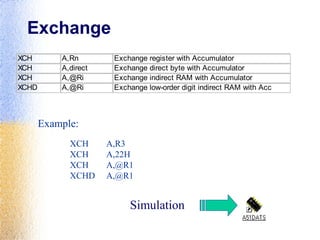
- 42. Exchange XCH A,Rn Exchange register with Accumulator XCH A,direct Exchange direct byte with Accumulator XCH A,@Ri Exchange indirect RAM with Accumulator XCHD A,@Ri Exchange low-order digit indirect RAM with Acc Example: XCH A,R3 XCH A,22H XCH A,@R1 XCHD A,@R1 Simulation
- 44. Arithmetic ADD A,Rn Add register to Accumulator ADD A,direct Add direct byte to Accumulator ADD A,@Ri Add indirect RAM to Accumulator ADD A,#data Add immediate data to Accumulator ADDC A,Rn Add register to Accumulator with carry ADDC A,direct Add direct byte to Accumulator with carry ADDC A,@Ri Add indirect RAM to Accumulator with carry ADDC A,#data Add immediate data to Accumulator with carry DIV AB Divide A by B MUL AB Multiply A and B SUBB A,Rn Subtract Register from Accumulator with borrow SUBB A,direct Subtract direct byte from Accumulator with borrow SUBB A,@Ri Subtract indirect RAM from Accumulator with borrow SUBB A,#data Subtract immediate data from Acc with borrow
- 45. Logic ANL A,Rn AND Register to Accumulator ANL A,direct AND direct byte to Accumulator ANL A,@Ri AND indirect RAM to Accumulator ANL A,#data AND immediate data to Accumulator ANL direct,A AND Accumulator to direct byte ANL direct,#data AND immediate data to direct byte ANL C,bit AND direct bit to carry ANL C,/bit AND complement of direct bit to carry ORL A,Rn OR register to Accumulator ORL A,direct OR direct byte to Accumulator ORL A,@Ri OR indirect RAM to Accumulator ORL A,#data OR immediate data to Accumulator ORL direct,A OR Accumulator to direct byte ORL direct,#data OR immediate data to direct byte ORL C,bit OR direct bit to carry ORL C,/bit OR complement of direct bit to carry
- 46. Logic XRL A,Rn Exclusive-OR register to Accumulator XRL A,direct Exclusive-OR direct byte to Accumulator XRL A,@Ri Exclusive-OR indirect RAM to Accumulator XRL A,#data Exclusive-OR immediate data to Accumulator XRL direct,A Exclusive-OR Accumulator to direct byte XRL direct,#data Exclusive-OR immediate data to direct byte Example: ANL A,1AH ANL 22H,#11H ORL A,R1 ORL A,@R1 XRL A,4FH XRL 2AH,#AAH Simulation
- 47. ADD A, Source ;A=A+SOURCE ADD A,#6 ;A=A+6 ADD A,R6 ;A=A+R6 ADD A,6 ;A=A+[6] or A=A+R6 ADD A,0F3H ;A=A+[0F3H]
- 48. SETB bit ; bit=1 CLR bit ; bit=0 SETB C ; CY=1 SETB P0.0 ;bit 0 from port 0 =1 SETB P3.7 ;bit 7 from port 3 =1 SETB ACC.2 ;bit 2 from ACCUMULATOR =1 SETB 05 ;set high D5 of RAM loc. 20h Note: CLR instruction is as same as SETB i.e: CLR C ;CY=0 But following instruction is only for CLR: CLR A ;A=0 Bit Addressable Page 359,360
- 49. SUBB A,source ;A=A-source-CY SETB C ;CY=1 SUBB A,R5 ;A=A-R5-1 ADC A,source ;A=A+source+CY SETB C ;CY=1 ADC A,R5 ;A=A+R5+1
- 50. DEC byte ;byte=byte-1 INC byte ;byte=byte+1 INC R7 DEC A DEC 40H ; [40]=[40]-1 CPL A ;1’s complement Example: MOV A,#55H ;A=01010101 B L01: CPL A ;A=10101010 B MOV P1,A ACALL DELAY SJMP L01 NOP & RET & RETI All are like 8086 instructions. CALL
- 51. ANL - ORL - XRL EXAMPLE: MOV R5,#89H ANL R5,#08H RR – RL – RRC – RLC A EXAMPLE: RR A
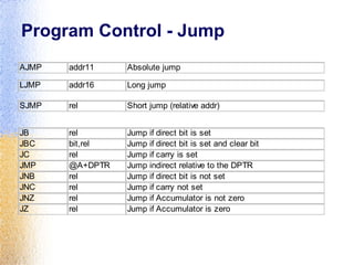
- 53. Program Control - Jump AJMP addr11 Absolute jump JB rel Jump if direct bit is set JBC bit,rel Jump if direct bit is set and clear bit JC rel Jump if carry is set JMP @A+DPTR Jump indirect relative to the DPTR JNB rel Jump if direct bit is not set JNC rel Jump if carry not set JNZ rel Jump if Accumulator is not zero JZ rel Jump if Accumulator is zero LJMP addr16 Long jump SJMP rel Short jump (relative addr)
- 55. Example: Unconditional Jump- LOOP MOV A,#30H MOV R1,A bla…bla… AJMP LOOP LJMPSJMP
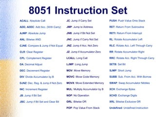
- 58. 8051 Instruction Set ACALL: Absolute Call ADD, ADDC: Add Acc. (With Carry) AJMP: Absolute Jump ANL: Bitwise AND CJNE: Compare & Jump if Not Equal CLR: Clear Register CPL: Complement Register DA: Decimal Adjust DEC: Decrement Register DIV: Divide Accumulator by B DJNZ: Dec. Reg. & Jump if Not Zero INC: Increment Register JB: Jump if Bit Set JBC: Jump if Bit Set and Clear Bit JC: Jump if Carry Set JMP: Jump to Address JNB: Jump if Bit Not Set JNC: Jump if Carry Not Set JNZ: Jump if Acc. Not Zero JZ: Jump if Accumulator Zero LCALL: Long Call LJMP: Long Jump MOV: Move Memory MOVC: Move Code Memory MOVX: Move Extended Memory MUL: Multiply Accumulator by B NOP: No Operation ORL: Bitwise OR POP: Pop Value From Stack PUSH: Push Value Onto Stack RET: Return From Subroutine RETI: Return From Interrupt RL: Rotate Accumulator Left RLC: Rotate Acc. Left Through Carry RR: Rotate Accumulator Right RRC: Rotate Acc. Right Through Carry SETB: Set Bit SJMP: Short Jump SUBB: Sub. From Acc. With Borrow SWAP: Swap Accumulator Nibbles XCH: Exchange Bytes XCHD: Exchange Digits XRL: Bitwise Exclusive OR Undefined: Undefined Instruction
- 60. ABITEC Application Board programming: 1. Eight large LED arrays 2. Eight switches array 3. Two Dual seven segment displays 4. DC Motor & Control 5. Semiconductor temperature sensor 6. Speaker 7. Heater control circuit 8. Telephone type keypad matrix 9. Fibre optic transmitter and receiver 10. Slider potentiometer - variable analogue voltage 11. An 8 bit Digital to Analogue Converter (DAC) and comparator to enable programming of ADC functions • Optional: • LCD interface • Stepper Motor Control (D4 - D7)
- 62. Time Delay •To write accurate time delay routine. •Using the DJNZ or CJNE instruction.
- 64. Interrupts 1. Enabling and Disabling Interrupts 2. Interrupt Priority 3. Writing the ISR (Interrupt Service Routine)
- 65. Interrupt Enable (IE) Register : • EA : Global enable/disable. • --- : Undefined. • ET2 :Enable Timer 2 interrupt. • ES :Enable Serial port interrupt. • ET1 :Enable Timer 1 interrupt. • EX1 :Enable External 1 interrupt. • ET0 : Enable Timer 0 interrupt. • EX0 : Enable External 0 interrupt.
- 66. Interrupt Vectors Interrupt Vector Address System Reset 0000H External 0 0003H Timer 0 000BH External 1 0013H Timer 1 001BH Serial Port 0023H Timer 2 002BH
- 67. Writing the ISR Example: Writing the ISR for Timer0 interrupt ORG 0000H ;reset LJMP MAIN ORG 000BH ;Timer0 entry point T0ISR: . ;Timer0 ISR begins . RETI ;return to main program MAIN: . ;main program . . END
Editor's Notes
- #7: Intel’s x86: 8086,8088,80386,80486, Pentium Motorola’s 680x0: 68000, 68010, 68020,68030,6040
- #13: versatility 多用途的: any number of applications for PC
- #15: processor 整合到整個系統中, 你只看到此系統的外觀, 應用, 感覺不到有 processor 在其中. Embedded system 通常只有一項應用, 而 PC 有許多 applications (game, accounting, fax, mail...) A printer is an example of embedded system since the processor inside it performs one task only.