


![DIRECT ADDRESSING
The instruction contains a field that holds the memory address of the operand
Opcode Operand address
Example:
ADD R1, A // R1=R1+ M[A]
EA = A
Single memory access is required to access the operand
No additional calculations required to determine the
operand address
Limited address space A = contents of an address field in the instruction](https://image.slidesharecdn.com/module3-250101173437-e5e9d581/85/module-3-instruction-set-and-control-unit-16-320.jpg)


![REGISTER INDIRECT ADDRESSING
The instruction specifies a register, and the register holds the
memory address where the operand is stored
EA= (R)
Only one memory reference is required to fetch operand
Example:
ADD R1, (R5) // PC =R1+ Mem[R5]](https://image.slidesharecdn.com/module3-250101173437-e5e9d581/85/module-3-instruction-set-and-control-unit-19-320.jpg)


![Basic Steps in Instruction Execution
• Fetch the contents of the memory location pointed to by the PC. Load these
contents into the IR to be interpreted.
IR [PC]
• Assuming that the memory is byte addressable, increment the contents of the PC
by 4.
PC PC + 4
• Carry out the actions specified by the instruction.
42](https://image.slidesharecdn.com/module3-250101173437-e5e9d581/85/module-3-instruction-set-and-control-unit-42-320.jpg)


module 3 instruction set and control unit
- 1. MODULE 3-Instruction SetS and control unit Dr. Sunil Kumar Pradhan SENSE/VIT-Chennai
- 2. 2 Introduction • The operation of the processor is determined by the instructions it executes, referred to as machine instructions or computer instructions. • The collection of different instructions that the processor can execute is referred to as the processor’s instruction set. • Provides the functional requirements for the processor • Instruction set architecture (ISA) • Interface between hardware and software • Interface between high level language and machine level language • Elements of ISA – instruction format, addressing modes, condition codes, instruction set
- 3. 3 Elements of a Machine Instruction • Operation code – Binary code that specifies the operation to be performed; also referred to as opcode (e.g., ADD, MOVE etc.) • Operands – One or more source/input operands to provide the input for an operation and destination/output operands to store the output of an operation • This field could contain data or registers or addresses (memory or I/O device). • Next instruction reference – Tells the processor where to fetch the next instruction after the execution of this instruction is complete • In most cases, the next instruction to be fetched immediately follows the current instruction. In those cases, there is no explicit reference to the next instruction.
- 4. 4 Instruction Format / Representation • General format • Example formats: Opcode Operand(s)/Address(es) Opcode Operand 1 (Input) Operand 2 (Output) 4 bits 6 bits 6 bits
- 5. 5 Mnemonics • It is difficult for a programmer to deal with binary representations of machine instructions and so it has become common practice to use a symbolic representation of machine instructions. • Opcodes are represented by abbreviations called mnemonics, that represent the operation to be performed. They have a fixed binary representation. • Examples from the ISA instruction set • ADD – Add • SUB – Subtract • MUL – Multiply • DIV – Divide • LOAD – Load data from memory • STOR – Store data to memory
- 6. 6 Instruction Types Based on Number of Addresses • One of the traditional ways of describing processor architecture is in terms of the number of addresses contained in each instruction. • In most architectures, many instructions have one, two, or three operand addresses and some may have an implicit operand (zero address). • The instructions may therefore be classified as • Three-address instruction • Two-address instruction • One-address instruction • Zero-address instruction
- 7. 7 Example THREE ADDRESS INSTRUCTIONS Each address field may specify either a processor register or a memory operand Advantage: Generate short programs Disadvantage: use long instructions
- 8. 8 Example TWO ADDRESS INSTRUCTIONS most popular instructions in commercial computers
- 9. 9 Example ONE ADDRESS INSTRUCTIONS The single accumulator based computers use one-address instructions. all instructions use an implied accumulator (AC) register. T is the temporary memory location required for storing the intermediate result.
- 10. 10 Example ZERO ADDRESS INSTRUCTIONS Zero-address instructions are used by stack-organized computers stack PUSH and POP require an address field to specify the destination or source of operand.
- 11. 11 Instruction Types • Data transfer (data storage/movement) instructions – Load, store, move, push, pop, exchange, input, output • Data manipulation/data processing instructions • Arithmetic instructions – INC, DEC, ADD, SUB, MUL, DIV • Logical instructions – AND, OR, NOT, XOR, TEST, CLR, CLC • Shift instructions – Logical and arithmetic shift, Rotate • Program control instructions • Branch/Jump – Conditional and unconditional • Skip – skip next instruction (increment PC by 2) • Call – Call a subroutine • Return – Return from subroutine Refer to Chapter 12 in the book by William Stallings
- 12. Addressing modes The way the operands are chosen during program execution is depend on addressing mode of instructions Addressing mode specifies a rule for interpreting or modifying the address field of instruction before the operand referenced
- 13. Purpose of addressing modes Computers using the addressing mode techniques for following provisions, -It gives programming versatility to user by providing such facilities as pointers to memory, counters for loop control, indexing of data, and program relocation. -To reduce number of bits in addressing field of instructions
- 14. 14 Addressing Modes • Immediate addressing • Direct addressing • Indirect addressing • Register addressing • Register indirect addressing • Displacement addressing • Relative addressing • Indexed addressing • Base register addressing • Implied addressing • Autoincrement or autodecrement addressing • Some notations • A – address • R – register • EA – effective (actual) address of the operand • (X) – contents of the memory location or register, X
- 15. Immediate addressing Operand is specified in the instruction itself Advantages: No memory reference is required to access the operand Fast Disadvantage : limited range (because limited number of bits are provided to specify the immediate data) Example: ADDI 25 // Acc =ACC+25 MOVI A, 06 // Load 06 to accumulator Opcode Immediate data
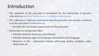
- 16. DIRECT ADDRESSING The instruction contains a field that holds the memory address of the operand Opcode Operand address Example: ADD R1, A // R1=R1+ M[A] EA = A Single memory access is required to access the operand No additional calculations required to determine the operand address Limited address space A = contents of an address field in the instruction
- 17. INDIRECT ADDRESSING The instruction gives a memory address in its address field which holds the address of the operand. EA = (A) Two memory accesses are required to get the operand values Instruction cycle time increases as there are two memory access Slower but can access large address space Not limited by number of bits in operand address like direct addressing Example: -ADD R1, (A) // R1=R1+(Mem (A)) -Content of location whose address is given in A is added with register R1 A = contents of an address field in the instruction
- 18. REGISTER ADDRESSING Register addressing is similar to direct addressing. The only difference is that the address field refers to a register rather than a main memory address EA = R Advantages Faster execution, since no memory access is required for getting operand Only a small address field is needed in the instruction Examples: ADD R1,R2,R3 // R1=R2+R3
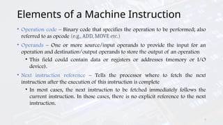
- 19. REGISTER INDIRECT ADDRESSING The instruction specifies a register, and the register holds the memory address where the operand is stored EA= (R) Only one memory reference is required to fetch operand Example: ADD R1, (R5) // PC =R1+ Mem[R5]
- 20. DISPLACEMENT ADDRESSING EA = A + (R) Instructions have two address field –one address field (offset value =A) used directly –other address field R = implicit reference based on opcode, refers to register whose content are added to A to produce effective address Three most common uses of displacement addressing: -Relative addressing -Base-register addressing -Indexing
- 21. RELATIVE ADDRESSING Also called PC relative addressing, implicitly referenced register is program counter (PC) The instruction specifies an offset of displacement(A), which is added to program counter (PC) to get effective address of the operand. Example: JR 20; branch to a location relative to the value 20 (offset)
- 22. INDEXED ADDRESSING The effective address is determined by adding the content of index register (XR) with the address part of the instruction
- 23. BASE REGISTER ADDRESSING The content of the base register (BR) is added to the address part of the instruction to obtain the effective address This mode is used for relocation of the programs in the memory. Relocation is a technique of moving program or data segments from one part of memory to another part of memory.
- 24. STACK ADDRESSING In this addressing mode, all the operands for an instruction are taken from the top of the stack. Instruction does not have any operand field. Example: SUB, ADD, PUSH X, POP X ADD instruction will POP top two operand from the stack, add them, and then PUSH the result to the top of the stack. Uses only opcode field, no address field
- 25. AUTO INCREMENT ADDRESSING This is similar to register indirect addressing mode Effective address of the operand is the contents of a register specified in the instruction. After accessing the operand, the content of the register is automatically incremented to point to the next consecutive memory location (step size d depend on size of operand accessed) Only one reference to memory is required to fetch the operand.
- 26. AUTO DECREMENT ADDRESSING Effective address of the operand is the contents of a register specified in the instruction. Before accessing the operand, the contents of this register are automatically decremented to point to the previous consecutive memory location (step size d depend on size of operand accessed)
- 27. IMPLIED ADDRESSING In this mode the operands are indicated implicitly by the instruction. The accumulator register is generally used to hold the operand and after the instruction execution the result is stored in the same register. For example, RAL; Rotates the content of the accumulator left through carry. CMA; Takes complement of the content of the accumulator This mode is very popular with 8-bit micro-processors such as the Intel’s 8085
- 28. Discussion problem Load to AC Mode Address = 500 Next Instruction 450 700 800 900 325 300 Address 200 201 202 Memory 399 400 500 600 702 PC 200 R1 400 XR 100 AC 800 PC = Program Counter R1 = Register XR = Index Register AC = Accumulator • Memory is having first instruction to load AC • Mode will specify the addressing mode to get operand. • Address field of instruction is 500. Find out the effective address of operand and operand value by considering different addressing modes. Suppose, the 2-word instruction stored at addresses 200 and 201 is an instruction: LDA 500; Load the accumulator (AC) register with the value as indicated by 500
- 29. Example problem Address Memory 200 201 Load to AC Mode Address = 500 Next Instruction 450 700 800 900 325 300 202 399 400 500 600 702 PC 200 R1 400 XR 100 AC 800 1. Immediate Addressing Mode • As instruction contains immediate number 500. • It is stored as address 201. Effective Address = 201 Operand = 500 AC 500
- 30. Example problem Load to AC Mode Address = 500 Next Instruction 450 700 800 900 325 300 Address 200 201 202 Memory 399 400 500 600 702 PC 200 R1 400 XR 100 AC 800 2. Register Addressing Mode • Register R1 contains 400. • As operand is in register so no any memory location. Effective Address = Nil Operand = 400 AC 400
- 31. Example problem Address 200 201 202 Memory 399 400 Load to AC Mode Address = 500 Next Instruction 450 700 800 900 325 300 500 600 702 PC 200 R1 400 XR 100 AC 800 3. Register Indirect Addressing Mode • Register R1 contains 400. • So effective address of operand is 400. • The data stored at 400 is 700. Effective Address = 400 Operand = 700 AC 700
- 32. Example problem Address 200 201 202 Memory 399 400 500 Load to AC Mode Address = 500 Next Instruction 450 700 800 900 325 300 600 702 PC 200 R1 400 XR 100 AC 800 4. Direct Addressing Mode • Instruction contains the address 500. • So effective address of operand is 500. • The data stored at 500 is 800. Effective Address = 500 Operand = 800 AC 800
- 33. Example problem Load to AC Mode Address = 500 Next Instruction 450 700 800 900 325 300 Address 200 201 202 Memory 399 400 500 600 702 PC 200 R1 400 XR 100 AC 800 5. Indirect Addressing Mode • Instruction contains the address 500. • Address at 500 is 800. • So effective address of operand is 800. • The data stored at 800 is 300. Effective Address = 800 Operand = 300 AC 300
- 34. Example problem Address 200 201 202 Memory 399 400 500 600 702 Load to AC Mode Address = 500 Next Instruction 450 700 800 900 325 300 PC 200 R1 400 XR 100 AC 800 6. PC Relative Addressing Mode • PC = 200. • Offset = 500. • Instruction is of 2 bytes. • So effective address = PC + 2 + offset = 200 + 500 +2 = 702 . • The data stored at 702 is 325. Effective Address = 702 Operand = 325 AC 325
- 35. Example problem Address 200 201 202 Memory 399 400 500 600 Load to AC Mode Address = 500 Next Instruction 450 700 800 900 325 300 702 PC 200 R1 400 XR 100 AC 800 7. Indexed Addressing Mode • XR = 100. • Base = 500. • So effective address = Base + XR = 500 + 100 = 600 . • The data stored at 600 is 900. Effective Address = 600 Operand = 900 AC 900
- 36. Example problem Address 200 201 202 Memory 399 400 Load to AC Mode Address = 500 Next Instruction 450 700 800 900 325 300 500 600 702 PC 200 R1 400 XR 100 AC 800 8. Autoincrement Addressing Mode • It is same as register indirect addressing mode except the contents of R1 are incremented after the execution. • R1 contains 400. • So effective address of operand is 400. • The data stored at 400 is 700. Effective Address = 400 Operand = 700 AC 700 R1 401
- 37. Example problem Address 200 201 202 Memory 399 Load to AC Mode Address = 500 Next Instruction 450 700 800 900 325 300 400 500 600 702 PC 200 R1 400 XR 100 AC 800 9. Autodecrement Addressing Mode • It is same as register indirect addressing mode except the contents of R1 are decremented before the execution. • R1 contains 400. • R1 is first decremented to 399. • So effective address of operand is 399. • The data stored at 399 is 450. Effective Address = 399 Operand = 450 AC 450 R1 399
- 38. Solution for problem Addressing Mode Effective Address Operand Immediate Addressing Mode 201 500 Register Addressing Mode Nil 400 Register Indirect Addressing Mode 400 700 Direct Addressing Mode 500 800 Indirect Addressing Mode 800 300 Relative Addressing Mode 702 325 Indexed Addressing Mode 600 900 Autoincrement Addressing Mode 400 700 Autodecrement Addressing Mode 399 450
- 39. Datapath
- 40. Introduction • Movement of data within a processor from one component to another • Registers, ALU, and the interconnecting bus collectively form the datapath • ALU • Performs arithmetic and logical operations • Contains control lines to select one of the possible ALU operations • Registers • General purpose registers to store data, memory address register (MAR), memory data register (MDR), program counter (PC), instruction register (IR), temporary registers (optional) • Buses • Internal (one or more) and external to carry the data from one component to another 40
- 42. Basic Steps in Instruction Execution • Fetch the contents of the memory location pointed to by the PC. Load these contents into the IR to be interpreted. IR [PC] • Assuming that the memory is byte addressable, increment the contents of the PC by 4. PC PC + 4 • Carry out the actions specified by the instruction. 42
- 43. Basic Steps in Instruction Execution • Most instructions involve the following operations: • Transfer a word of data from one processor register to another or the ALU • Perform an arithmetic or logical operation and store the result in a processor register • Fetch the contents of a memory location and load them into a processor register • Store a word of data from a processor register into a memory location 43
- 44. Register Transfer • Enable the output of by setting to 1. This places the contents of on the processor bus. • Enable the input of the register b setting to 1. This loads data from the processor into register . 44 MOV R1, R4
- 45. Arithmetic and Logic Operations • , • , , , • , 45 ADD R1, R2, R3
- 46. Memory Read and Write • Memory Read • Memory Write 46 MOV (R1), R2 MOV R2, (R1)
- 47. Execution of a Complete Instruction 47 ADD (R3), R1
- 48. Multi Cycle Data Path Architecture 48
- 49. Why Multi Cycle Data Path ? • In a single cycle data path architecture , exclusively single data word could be moved through the bus in a given clock cycle • Because of this no of steps needed to execute the inst increases • To decrease the no of steps needed to execute the inst and to transfer more than one word in a clock cycle we go for multicycle 49
- 50. How Multi Cycle Data Path Works • Three buses are used to link reg and ALU of the CPU • All GPR , R1, R2…Rn are presented in one block known as reg files • Figure 2. shows the register files has three ports 50
- 51. Figure 2. Multi Cycle Data Path Architecture 51
- 52. How Multi Cycle Data Path Works • One input and two output ports • Therefore data of three registers are possible to access in single clk cycle • Through Bus C, the value could be put in one reg • Data from two regs is available through Bus A and Bus B 52
- 53. How Multi Cycle Data Path Works • Bus A and B are used to move the source operands to i/ps of the ALU A and B • After ALU process is executed the resultant is moved to destination operand through the bus C • Separate incremental unit is provided to increment the value of PC after every instruction is executed 53
- 54. Execution of Instruction using Multi Cycle Data Path Add R1, R2, R3 Control Sequence • The inst adds the values of register R2 & R3 and stores the resultant in R1 54
- 55. Multi Cycle Data Path Add R1, R2, R3 Control Sequence Explanation • Step 1: The value of the PC are moved to MAR by means of Bus B to begin Read operation. PCMAR • Parallelly PC is incremented point towards the next instruction PCPC+1 55
- 56. Multi Cycle Data Path Add R1, R2, R3 Control Sequence Explanation • Step 2: The processor waits for WMFC signal from the memory • Step 3: The inst code is moved from MDR to IR MDR IR • Step 4: The inst decoder decodes the IR contents 56
- 57. Multi Cycle Data Path Add R1, R2, R3 Control Sequence Explanation • Step 4: Two values from reg R2 & R3 are made accessible at inputs A and B of ALU by means of Bus A & B • By activating the Add signal two inputs are added • Through Bus C the resultant is stored in R1 57