


![1
Chapter 1 Introduction
1.1. Motivation
There is significant growth today in the area of mobile wireless data connectivity, ranging
from home and office networks to public networks, such as the emerging third generation
mobile network. In all these areas, there is expectation of an increase in support for
multimedia rich services, especially since increased data rates make this more feasible. While
there is strong incentive to develop and provide such services, the network owner/operator is
faced with many commercial and technical considerations to balance, including the following:
Consideration 1. Given a finite radio spectrum resource, there is a need to balance the
increasing bandwidth demands of any one single service against the requirement to support
as many concurrent services/subscribers as possible without causing network congestion or
overload.
Consideration 2. The need to cater for user access devices with varying complexities and
capabilities (for example, from laptop PCs to PDAs and mobile phones).
Consideration 3. The need to support end-to-end services, which may be conveyed across
numerous heterogenous networks and technology standards. For example, data originating
in a corporate Ethernet network may be sent simultaneously to both:
a) a mobile phone across a public mobile network.
b) a PC on a home wireless LAN via a broadband internet connection.
Consideration 4. The need to provide services which can adapt and compensate for the error
characteristics of a wireless mobile environment.
Digital video applications are expected to form a part of the increase in multimedia services.
Video conferencing is just one example of real-time video applications that places great
bandwidth and delay requirement demands on a network. In fact, [21] asserts that most real-
time video applications exceed the bandwidth available with existing mobile systems, and
that innovations in video source and channel coding are therefore required alongside the
advances in radio and air interface technology.
Within video compression and coding research, there has been much interest in scalable video
coding techniques. Chapter 23 of [21] defines video scalability as “the property of the
encoded bitstream that allows it to support various bandwidth constraints or display
resolutions”. This facility allows video performance to be optimised depending on both
bandwidth availability and decoder capability, albeit at some penalty to compression
efficiency. In the case of broadcast transmission over a network, a rate control mechanism
can be employed between video encoder and decoder that dynamically adapts to the
bandwidth demands on multiple links. The interest in scalable video is clearly justified by the
scenario where it is desirable to avoid compromising the quality of decoded video for one
user with high bandwidth and high specification user equipment (e.g. a PC via a broadband
internet connection), while still providing a reduced quality video to a second user with low
bandwidth and low specification equipment (e.g. a mobile phone over a public mobile
network). Another illustration of this problem is given in [19], which highlights the similar
predicament currently facing the web design community. With the more recent introduction
of web-connected platforms, such as PDAs and WAP phones, web designers are now
challenged to produce web content which can dynamically cater for varying levels or classes
of access device capability (e.g. screen size and processing power). One potential strategy](https://image.slidesharecdn.com/51b51a0d-43bc-4eaf-8019-09bd462be671-151215105039/85/MSC-Thesis-Wireless-Video-over-HIPERLAN2-JustinJohnstone-9-320.jpg)
![2
identified in [19] echoes the video scalability principle, in that ideally, the means to derive
“reduced complexity” content should be embedded within each web page. This would allow
web designers to avoid the undesired task of publishing and maintaining multiple sites - each
dedicated to the capabilities of each class of access device. With the potential for significant
growth in video applications via broadband internet and third generation mobile access, it is
therefore inevitable that for the same reason, scalable video will become increasingly
important too.
1.2. Scope of Investigations
The brief of this project is to focus on optimising aspects of scalable video coding over a
wireless LAN, and specifically the HiperLAN/2 standard [2]. Within the HiperLAN/2
standard, a key feature of the physical layer is that it supports a number of different physical
modes, which have differing data rates and link quality requirements. Specifically, the modes
with higher nominal data rates require higher carrier-to-interference (C/I) levels to be able to
achieve near their nominal data rates. Performance studies ([7],[16],[20]) have shown that as
the C/I decreases, higher overall throughput can be maintained if the physical mode is
reduced at specific threshold points. The responsibility to monitor and dynamically alter
physical modes is designated to a function referred to as “link adaptation”. However, as this is
function is not defined as part of the HiperLAN/2 standard, there is interest to propose
algorithms in this area. This project was tasked to recommend an optimal scheme to convey
layered video data over HiperLAN/2, including assessment of link adaptation algorithms.
However, when making proposals in any one specific area of mobile multimedia applications,
it is vital to consider these in the wider context of the entire system in which they will
operate. Therefore this report also considers many of the more general techniques in the area
of “wireless packet video”.
1.3. Organisation of this Report
The remainder of this report is organised as follows: Chapter 2 commences with an
introduction of video coding theory. It then provides an overview of nature of errors in a
wireless environment, and what effect these have on the performance of video coding.
Chapter 2 concludes with an overview of the standards used in the project, namely H.263+
and HiperLAN/2. Chapter 3 presents a review of some existing wireless packet video
techniques, which are considered for investigation in this project. Chapter 4 proposes the
approach intended to convey layered video bitstream over HiperLAN/2. The chapter also
considers which of the more general techniques to apply during testing. Chapter 5 describes
the implementation of components in the simulation system used for investigations, and then
introduces the specific tests to be conducted. Chapter 6 discusses test results, and chapter 7
presents conclusions, including a list of areas identified for further investigation.](https://image.slidesharecdn.com/51b51a0d-43bc-4eaf-8019-09bd462be671-151215105039/85/MSC-Thesis-Wireless-Video-over-HIPERLAN2-JustinJohnstone-10-320.jpg)
![3
Chapter 2 Review of Theory and Standards
This chapter introduces some useful concepts regarding video coding, wireless channel errors
and their effect on coded video. The chapter concludes with an overview of the standards
used in the project; H.263+ and HiperLAN/2.
2.1. Video Coding Concepts
The following basic concepts are discussed in this section:
Digital image capture and processing considerations
Picture Formats
Redundancy and Compression
Video Coding Techniques
Quality assessment
The video coding standards considered for use on this project include H.263+, MPEG-2 and
MPEG-4, since all these standards incorporate scalability. While the basic concepts discussed
in this section are common to all these standards, many of the illustrations are tailored to
highlight specific details of H.263+, since this is the standard selected for use in this project.
Further details of this standard, including it scalability modes, are discussed later in section
2.5.1.
2.1.1. Digital Capture and Processing
Digital images provide a two dimensional representation of the visual perception of the three-
dimensional world. As indicated in [22], the process to produce digital images involves the
following two stages, shown also in Figure 2-1 below:
Sampling: Here an image is partitioned into a grid of discrete regions called
picture elements (abbreviated “pixels” or “pels”). An image capture
device obtains measurements for each pixel. Typically this is performed
by a scan, which commences in one corner of the grid, and proceeds
sequentially row by row, and pixel by pixel within each row, until
measurements for the last pixel, in the diagonally opposite corner to the
start point are recorded. Commonly, image capture devices record the
colour components for each pixel in RGB colour format.
Quantisation: Measured values for each pixel are mapped to the nearest integer within
a given range (typically this range is 0 to 255). In this way, digitisation
results in an image being represented by an array of integers.
Note:. The RGB representation is typically converted into YUV format
(where Y represents luminance and U,V represent chrominance
values). The significant benefit of this conversion is that it
subsequently allows more efficient coding of the data.](https://image.slidesharecdn.com/51b51a0d-43bc-4eaf-8019-09bd462be671-151215105039/85/MSC-Thesis-Wireless-Video-over-HIPERLAN2-JustinJohnstone-11-320.jpg)


![8
2.1.4. Coding Categories
There is a wide selection of strategies for video coding. The general categories into which
these strategies are allocated is shown in Figure 2-3 below. As indicated by the shading in the
diagram, this project makes use of DCT transform coding, which is categorised as a lossy,
waveform based method.
Categories of Image and Video Coding
MODEL based WAVEFORM based
Statistical Universal Spatial Frequency
LossyLoss-less
example:
- wire frame modelling
examples:
- sub-band
examples:
- fractal
- predicitive(DPCM)
example:
- ZIP
examples:
- Huffman
- Arithmetic - DCT transform
Note: shaded selections identify the categories and method considered in this project.
Figure 2-3 : Categories of Image and Video Coding
2.1.5. General Coding Techniques
To achieve compression, a video encoder typically performs a combination of the following
techniques, which are discussed briefly in the sub-sections below this list:
Block Structure and Video Layer Decomposition
Intra and Inter coding: Intraframe prediction, Motion Estimation
Block Coding: Transform, Quantisation and Entropy Coding.
2.1.5.1. Block Structuring
The raw array of data samples produced by digitisation is typically restructured into a format
that the video codec can take advantage of during processing. This new structure typically
consists of a four layer hierarchy of sub-elements. A graphical view of this decomposition of
layers, with specific values for QCIF and H.263+ is given in Figure 2-4 below. When coding
schemes apply this style of layering, with the lowest layer consisting of blocks, the coding
scheme is said to be “block-based” or “block-structured”. Alternatives to block-based coding
are object- and model-based coding. While these alternatives promise the potential for even
lower bit rates, they are less mature than current block-based techniques. These will not be
covered in this report, however more information can be found in chapter 19 of [21].](https://image.slidesharecdn.com/51b51a0d-43bc-4eaf-8019-09bd462be671-151215105039/85/MSC-Thesis-Wireless-Video-over-HIPERLAN2-JustinJohnstone-16-320.jpg)


![12
Notes:
1) For highly correlated samples in a uniform region of the frame, the prediction will be very
precise, resulting in a small or zero error term, which can be coded efficiently.
2) When edges occur between non-uniform regions within an image, neighbouring samples
will be uncorrelated and the prediction will produce a large error term, which diminishes
coding efficiency. However, chapter 2 of [23] highlights the following two factors which
determine that this technique does provide overall compression benefits:
a) Within a wide variety of naturally occurring image data, the vast majority of error
terms are very close to zero – hence on average, it is possible to code error terms
efficiently.
b) While the HVS is very sensitive to the location of edges, it is not as sensitive the
actual magnitude change. This allows that the large magnitude error terms can be
quantised coarsely, and hence coded more efficiently.
3) Since this technique only operates on elements within the same frame, the “intraframe”
aspect of it’s name is consistent with the definitions in Table 2-5. However, since coded
data depends on previous samples, it is subject to error propagation in a similar way to
interframe coding. This error propagation may manifest itself as horizontal and/or vertical
streaks to the end of a row or column.
2.1.5.2.3. Intra Coding
When a block is intra coded (for example, when a motion vector cannot be used), the encoder
translates the data in the block into a more compact representation before transmitting it to
the decoder. The objective of such translation (from chapter 3 of [23]) is: “to alter the
distribution of the values representing the luminance levels so that many of them can either be
deleted entirely, or at worst be quantised with very few bits”.
The decoder must perform the inverse of the translation actions to restore the block back to
the original raw format. If the coding method is categorised as being loss-less, then the
decoder will be able to reconstruct the original data exactly. However, this project makes use
of lossy a coding method, where a proportion of the data is permanently lost during coding.
This restricts the decoder to reconstruct an approximation of the original data.
The generic sequence of actions involved in block encoding and decoding are shown in
Figure 2-7 below. Each of these actions is discussed in the paragraphs below, which also
introduce some specific examples relevant to this project.
Transform
block
(e.g. 8x8)
Entropy
Code
Quantise
Inverse
Transform
Requantise
transmission
channel
or storage
Entropy
Decode
ENCODER
block
(e.g. 8x8)
DECODER
Figure 2-7 : Block Encode/Decode Actions](https://image.slidesharecdn.com/51b51a0d-43bc-4eaf-8019-09bd462be671-151215105039/85/MSC-Thesis-Wireless-Video-over-HIPERLAN2-JustinJohnstone-20-320.jpg)
![13
Transformation
This involves translation of the sampled data values in a block into another domain. In the
original format, samples may be viewed as being in the spatial domain. However, chapter 3 of
[23] indicates these may equally be considered to be in the temporal domain, since the
scanning process during image capture provides a deterministic mapping between the two
domains. The coding category highlighted in Figure 2-3 for use in this project is
“Waveform/Lossy/Frequency”. The frequency aspect refers to the target domain for the
transform. The transform can be therefore be viewed as a time to frequency domain
transform, allowing selection of a suitable Fourier Transform based method. Possibilities for
this include:
Walsh-Hadamard Transform (WDT)
Discrete Cosine Transform (DCT)
Karhunen-Loeve Transform (KLT)
The DCT is a popular choice for many standards, including JPEG and H.263. The output of
the transform on an 8x8 (for example) block results in the same number (64) of transform
coefficients, each representing the magnitude of frequency component. The coefficients are
arranged in the block with the single DC coefficient in the upper left corner, then zig-zag
along diagonals with the highest frequency coefficient in the lower right corner of the block
(see Figure 2-8). Since the transform produces the same number of coefficients as there were
to start with; it does not directly achieve any compression. However, compression is achieved
in the subsequent step, namely quantisation. Further details of the DCT transform are not
presented here, as these are not directly relevant to this project, however [23] may be referred
to for more details.
Quantisation
This operation is performed on the transform coefficients. These coefficients usually have
widely varying range of magnitudes, with a typical distribution as shown in the left side of
Figure 2-8 below. This distribution makes it possible to ignore some of the coefficients with
sufficiently small magnitudes. This is achieved by applying a variable quantisation step size
to positions in the block, as shown in the right side of Figure 2-8 below. This approach
provides highest resolution to the DC and high magnitude coefficients in the top left of the
block, while reducing resolution toward the lower right corner of the block. The output of the
quantisation typically results in a block with some non-zero values towards the upper left of
the block, but many zeros towards the lower right corner of the block. Compression is
achieved when these small or zero magnitude values are coded more efficiently as seen in the
subsequent step, namely Entropy Coding.
DC
large magnitude
low frequency
coefficients
small magnitude
high frequency
coefficients
8x8 block of transform coefficients
smallest
quantistion values
- better resolution
largest
quantisation values,
lowest resolution
corresponding 8x8 matrix of quantisation
coefficients
increasing
quantisation
values
increasing
quantisation
values
coefficients
loaded
diagnoanally
Figure 2-8 : Transform Coefficient Distribution and Quantisation Matrix](https://image.slidesharecdn.com/51b51a0d-43bc-4eaf-8019-09bd462be671-151215105039/85/MSC-Thesis-Wireless-Video-over-HIPERLAN2-JustinJohnstone-21-320.jpg)
![14
Entropy Coding
This type of source coding provides data compression without loss of information. In general,
source coding schemes map each source symbol to a unique (typically binary) codeword prior
to transmission. Compression is achieved by coding as efficiently as possible (i.e. using the
fewest number of bits). Entropy coding achieves efficient coding by using variable length
codewords. Shorter codewords are assigned to those symbols that occur more often, and
longer codewords are assigned to symbols that occur less often. This means that on average,
shorter codewords will be used more often, resulting in fewer bits being required to represent
an average sequence of source symbols.
An optional, but desirable property for variable length codes is the “prefix-free” property.
This property is satisfied when no codeword is the prefix of any other codeword. This has the
benefit that codewords are “instantaneously decodable”, which implies that the end of a
codeword can be determined as the codeword is read (and without the need to receive the start
of the next codeword). Unfortunately, there are also some drawbacks in using variable length
codes. These include:
1) The instantaneous rate at which codewords are received will vary due to the variable
codeword length. A decoder therefore requires buffering to smooth the rate at which
codewords are received.
2) Upon receipt of a corrupt codeword, the decoder may lose track of the boundaries
between codewords. This can result in the following two undesirable outcomes, which are
relevant as their occurrence is evident later in this report:
a) The decoder may only recognise the existence of an invalid codeword sometime after
it has read beyond the start of subsequent codewords. In this way, a number of valid
codewords may be incorrectly ignored until the decoder is able to resynchronise itself
to the boundaries of valid codewords.
b) When attempting to resynchronise, a “false synchronisation” may occur. This will
result in further loss of valid codewords until the decoder detects this condition and is
able to establish valid resynchronisation.
An example of a prefix-free variable length code is the Huffman Code. This has the
advantage that it “can achieve the shortest average code length” (chapter 11 of [24]). Further
details of Huffman coding are not covered here, as they are not of specific interest to this
project.
Within a coded block of data, it common to observe a sequence of repeated data values. For
example, the quantised transform coefficients near the lower right corner of the block are
often reduced to zero. In this case, it is possible to modify and further improve the
compression efficiency of Huffman (or other source) coding, by applying “Run-Length
coding”. Instead of encoding each symbol in a lengthy run of repeated values, this technique
describes the run with an efficient substitution code. This substitution code typically consists
of a control code and a repetition count to allow the decoder to recreate the sequence exactly.
2.1.6. Quality Assessment
When developing video coding systems, it is necessary to provide an assessment of the
quality of the recovered decoded video. Such assessments provide performance indicators
which are necessary to optimise system performance during development or even to confirm
the viability of the system prior to deployment. It is usually desirable to perform subjective
and quantitative assessments of video performance. It is quite common to perform
quantitative assessments during earlier development and optimisation phases, and then to](https://image.slidesharecdn.com/51b51a0d-43bc-4eaf-8019-09bd462be671-151215105039/85/MSC-Thesis-Wireless-Video-over-HIPERLAN2-JustinJohnstone-22-320.jpg)


![19
2.4. Impact of Errors on Video Coding
Chapter 27 of [21] provides a good illustration of the potentially drastic impact of errors in a
video bitstream. Table 2-8 provides a summary of these impacts, showing the type of error
and it’s severity. When error propagation results, the table categorises the type of propagation
and lists some typical means to reduce the extent of the propagation. The examples in this
table are ordered from lowest to highest severity impact.
Table 2-8 : Impact of Errors in Coded Video
Example 1:
Location of error: Within a macroblock of an I-frame, which is not used as a
reference in motion estimation.
Extent of impact: The error is limited to a (macro)block within one frame only –
there is no propagation to subsequent frames. This therefore
results in a single block error.
Severity: Low
Error Propagation
Category:
Not applicable – no propagation
Example 2:
Location of error: In motion vectors of a P-frame, that does not cause loss of
synchronisation.
Extent of impact: Temporal error propagation results, with multiple block errors
in subsequent frames until the next intra coded frame is
received.
Severity: Medium
Error Propagation
Category:
Predictive Propagation
Propagation Reduction
strategy:
The accepted recovery method is to send an intra coded frame
to the decoder.
Example 3:
Location of error: In a variable length codeword of a block which is used for
motion estimation, and causes loss of synchronisation.
Extent of impact: When the decoder loses synchronisation, it will ignore valid
data until it is able to recognise the next synchronisation
pattern. If only one synch pattern is used per frame, the rest of
the frame may be lost. If the error occurred at the start of an I-
frame, not only is this frame lost, but subsequent P-frames
will also be severely errored, due to temporal propagation.
This potentially results in multiple frame errors.
Severity: High
Error Propagation
Category:
Loss of Synchronisation
Propagation Reduction
strategy:
One way to reduce the extent of this propagation, is to insert
more synchronisation codewords into the bitstream so that
less data is lost before resynchronisation is gained. This has
the drawback of increasing redundancy overheads.](https://image.slidesharecdn.com/51b51a0d-43bc-4eaf-8019-09bd462be671-151215105039/85/MSC-Thesis-Wireless-Video-over-HIPERLAN2-JustinJohnstone-27-320.jpg)
![20
Example 4:
Location of error: In the header of a frame.
Extent of impact: Information in the header of a frame contains important
information about how data is interpreted in the remainder of
the frame. If this information is corrupt, data in the rest of the
frame is meaningless – hence the entire frame can be lost.
Severity: High
Error Propagation
Category:
Catastrophic
Propagation Reduction
strategy:
Protect the header by a powerful channel code to ensure it is
received intact. Fortunately, header information represents a
small percentage of the bitstream, so the overhead associated
with protecting it is less onerous than might be expected.
Based on the potentially dramatic impact of these errors, it is evident that additional
techniques are required to protect against these errors and their effects in order to enhance the
robustness of coded video. Examples of such techniques are discussed in chapter 3.
2.5. Standards overview
2.5.1. Selection of H.263+
H.263+ was selected as the video coding standard for use on this project. Justifications for
choosing H.263+ in preference to MPEG include the following:
H.263+ simulation software is more readily available and mature than MPEG software.
Specifically, an H.263+ software codec [3] is available within the department, and there
are research staff familiar with this software.
The H263+ specification is much more concise than the MPEG specifications, and given
the timeframe of this project, it was considered more feasible to work with this smaller
standard.
H.263+ is focussed at lower bit rates, which is of more interest in this project. This focus
is based on the anticipation of significant growth in video applications being provided
over the internet and public mobile networks. To make maximum use of their bandwidth
investments, mobile network operators will be challenged to provide services at lower bit
rates.
Based on this choice, some unique aspects of MPEG-2 and MPEG-4, such as those listed
below, are not covered in this project:
Fine-Grained-Scalability (FGS).
Higher bit rates (MPEG-2 operates from 2 to 30Mbps).
Content based scalability (MPEG-4).
Coding of natural and synthetic scenes (MPEG-4)](https://image.slidesharecdn.com/51b51a0d-43bc-4eaf-8019-09bd462be671-151215105039/85/MSC-Thesis-Wireless-Video-over-HIPERLAN2-JustinJohnstone-28-320.jpg)


![23
EI
I P P
Spatial Scalability
Enhancement
Layer
(e.g. CIF)
BASE
layer
(e.g. QCIF)
EP EP
key:
direction of prediction
Figure 2-11 : Spatial scalability
2.5.2.5. Test Model Rate Control Methods
[6] highlights the existence of a rate control algorithm called TMN-8, which is described in
[27]. Although not an integral part of the H.263+ standard, this algorithm is mentioned here
as it is incorporated within the video encoder software used on this project. TMN-8 controls
the dynamic output bit rate of the encoder according to a specified target bit rate. It achieves
this by adjusting the macroblock quantisation coefficients. Larger coefficients will reduce the
bit rate and smaller coefficients will increase the bit rate.
2.5.3. HiperLAN/2
This section presents a brief overview of the HiperLAN/2 standard, and is largely based on
[15].
2.5.3.1. Overview
HiperLAN/2 is an ETSI standard (see [2], [15] and [26]) defining a high speed radio
communication system with typical data rates between 6 to 54 Mbit/s, operating in the 5 GHz
frequency range. It connects portable devices, referred to as Mobile Terminals (MTs), via a
base station, referred to as an Access Point (AP), with broadband networks based on IP, ATM
or other technologies. HiperLAN/2 supports restricted user mobility, and is capable of
supporting multimedia applications. A HiperLAN/2 network may operate in one of the two
modes listed below. The first mode is more typical for business environments, whereas the
second mode is more appropriate for home networks:
a) “CENTRALISED mode”: where a one or more fixed location APs are configured to
provide a cellular access network to a number MTs operating within the coverage area.
All traffic passes through an AP either to an external core network or to another MT
within the coverage area.
b) “DIRECT mode”: where MTs communicate directly with one another in an ad-hoc
manner, without routing data via an AP. One of the MTs may act as a Central Controller
(CC), which can provide connection to an external core network.
ETSI only standardised the radio access network and some of the convergence layer
functions, which permit connection to a variety of core networks. The defined protocol layers
are shown in Table 2-9 below, and these are described in more detail in each of the following
sections.](https://image.slidesharecdn.com/51b51a0d-43bc-4eaf-8019-09bd462be671-151215105039/85/MSC-Thesis-Wireless-Video-over-HIPERLAN2-JustinJohnstone-31-320.jpg)


![26
2.5.3.2.2. Physical Layer Transmit Sequence
In the transmit direction, the sequence of operations performed on data received from the
DLC prior to transmission across the air interface is shown in Figure 2-13 below, and a brief
description of each action is given following this.
1.
scrambling
5.
sub-carrier
modulation
4.
Interleaving
2.
convolutional
coding
data from
DLC layer
8.
RF Modulation and
Transmission
7.
PHY burst
formatting
6.
OFDM
3.
puncturing
Figure 2-13 : HiperLAN/2 Physical Layer Transmit Chain
Transmit Actions:
1. Scrambling: This is performed to avoid long sequences of ones or zeroes
occurring, which can result in undesirable DC bias.
2. Convolutional
encoding:
Channel coding provides error control to improve performance.
Note that the decoding process can apply hard or soft decision
decoding. Soft decision typically improves coding gain by
approximately 2dB, at the expense of increased decoder
complexity.
3. Puncturing The standard convolutional coding above is modified by
omitting some transmitted bits to achieve a higher coding rate.
Different “puncturing patterns” are applied dependant on the
PHY mode selected to achieve the code rates in column 3 of
Table 2-11.
4. Interleaving: Block interleaving is applied as it to improves resilience to
burst errors.
5. Sub-carrier
modulation:
Dependant on the PHY mode selected, the modulation scheme
listed in column 2 of Table 2-11 is applied. The order of these
schemes is directly proportional to the maximum data rate
achievable.
6. Orthogonal Frequency
Division Multiplexing
(OFDM):
Strong justifications for applying this technique are that it
offers good tolerance to multipath distortion [17] and to
narrow–band interferers [18]. It achieves this by spreading the
data over a number of sub-carriers. In HiperLAN/2 this is
achieved by an inverse FFT of 48 data sub-carriers to produce
each OFDM symbol. A guard period is inserted between each
OFDM symbol to combat ISI.
7. PHY Burst
Formatting
The baseband data is formatted into the appropriate PHY burst
format according to the phase within the MAC frame that it
will be transmitted.
8. RF modulation The baseband signal is modulated with the RF carrier and
transmitted over the air interface.](https://image.slidesharecdn.com/51b51a0d-43bc-4eaf-8019-09bd462be671-151215105039/85/MSC-Thesis-Wireless-Video-over-HIPERLAN2-JustinJohnstone-34-320.jpg)
![27
HiperLAN/2 will be deployed in a variety of physical environments, and [16] identifies six
channel models specified to represent such environments. These models are often used in
literature ([7] and [16]) as common reference points when quoting performance in
HiperLAN/2 simulations. These models are repeated in Table 2-12 below for reference.
Table 2-12 : HiperLAN/2 Channel Modes
Channel
Model
Identifier
RMS
Delay
spread
[ns]
Characteristic Environment
A 50 Rayleigh Office Near Line of Sight
(NLOS)
B 100 Rayleigh Open space/Office NLOS
C 150 Rayleigh Large Open Space NLOS
D 200 Rician Large Open Space NLOS
E 250 Rayleigh Large Open Space NLOS
2.5.3.3. DLC layer
This layer provides services to higher layers in the following two categories, discussed below.
2.5.3.3.1. Data transport functions
There are two components to data transport: Medium Access Control (MAC) and Error
Correction (EC).
Medium Access Control
In HiperLAN/2, Medium Access Control is managed centrally from an AP, and it’s purpose is
to control the timing of each MT’s access to the air interface, such that minimum conflict for
this shared resource is achieved. MAC is based on a Time Division Duplex/Time Division
Multiple Access (TDD/TDMA) approach with a 2ms frame format, divided into a number of
distinct phases, each dedicated to conveying specific categories of information in both uplink
and downlink directions. An MT is required to synchronise with the MAC frame structure
and monitor information in the broadcast phase of the frame, before it can request use of radio
resources from the AP. An MT requests resources by an indication in the “Random Access
phase” of the MAC frame. Upon detection of this request, the AP will dynamically allocate
timeslots within the downlink, uplink or Direct Link phases of the frame for the MTs to use
for ongoing communications.
Within the DLC layer, data is categorised and passed along two distinct paths, referred to as
the “Control Plane” and “User Plane”. The Control Plane contains protocol signalling
messages, typically used to dynamically establish and tear down connections between the two
communicating end points. The User plane contains actual “user data” from higher layers.
Both categories of data are conveyed in the Downlink, Uplink or Direct Link phases of a
MAC frame, and are contained in one of 2 formats; namely the “long PDU” or “short PDU”
formats. Control plane data is contained in the 9 octet “short PDU”, and User Plane data is
contained in the 54 octet “long PDU”. In the remainder of this report, reference to a
HiperLAN/2 “packet” implies this long PDU structure, which is shown in Figure 2-14 below.](https://image.slidesharecdn.com/51b51a0d-43bc-4eaf-8019-09bd462be671-151215105039/85/MSC-Thesis-Wireless-Video-over-HIPERLAN2-JustinJohnstone-35-320.jpg)


![30
Table 3-2 : Error Protection Techniques Considered
No. Technique Algorithm
Optimisation
Error
Control
Error
Concealment
1. Scaled/Layered parameters
(e.g. number of layers, relative bit rates, modes)
2. Rate control.
3. Lost packet Treatment.
4. Link adaptation – optimisation of throughput
5. Intra Replenishment.
6. Adaptive encoding with feedback.
7. Prioritisation Packet queuing and dropping.
8. Automatic Repeat Request (ARQ).
9. Forward Error Correction (FEC).
10. Unequal Packet-loss Protection (UPP).
11. Improved resynchronisation.
12. Error Resilient Entropy Coding (EREC).
13. Two-way VLC coding.
14. Lost Content Prediction and Replacement
3.2. Techniques Considered
3.2.1. Layered Video and Rate Control
The primary benefit of scaleable video is that it allows the following chain of possibilities:
Defining
layers in
video
bitstream
Prioritisation
to be assigned
to these layers
Rate Control to be selectively
applied to these priority layers.
Unequal Packet Loss Protection
(UPP) to be applied to these
priorities.
allows
allows
Scalability was created specifically with the intent to allow video performance to be
optimised depending on both bandwidth availability and decoder capability. A layered
bitstream permits a scalable decoder to select and utilise a subset of the lower layers within
the total bitstream suitable to the decoder’s capabilities, while still producing a usable, albeit
reduced quality video output. Scalable video is less compression efficient than non scalable
video [25], however it offers more flexibility to changing channel bandwidths.
A rate control function may be employed at various nodes in a network to dynamically adapt
the bit rate of the bitstream prior to onward transmission over the subsequent channel.
Typically the rate control function is controlled by feedback indications from the transmission
channel and/or the decoder as well. In a broadcast transmission scenario, with one source
video bitstream distributed to many destination decoders, it is possible for multiple rate
control functions to be employed simultaneously to adapt to the unique bandwidth and
display capabilities of each of the destination decoders. In those cases where rate control
reduces the transmitted bit rate in a congested network, this reduces bandwidth demands on
the network, which may actually serve to reduce congestion in the network. The reduction in](https://image.slidesharecdn.com/51b51a0d-43bc-4eaf-8019-09bd462be671-151215105039/85/MSC-Thesis-Wireless-Video-over-HIPERLAN2-JustinJohnstone-38-320.jpg)
![31
bit rate is typically achieved by dropping frames from higher (lower priority) layers until an
acceptable threshold is reached.
While the video coding standards define the syntax for layered bitstreams, settings such the
relative bit rates of each layer, and algorithms to prioritise and protect these layers are left to
the discretion of system designers. [25] is highly relevant, as it contains the following
findings on layered H.263+ video settings:
1. Coding efficiency decreases as the number of layers increases.
2. Layered video can only be decoded at the bit rate at which is it was encoded.
3. Based on point 2, it is therefore necessary to know the most suitable bit rates to encode
the base and enhancement layers at prior to encoding. However, this constraint can
eliminated if an adaptive algorithm using feedback from the transmission channel and/or
the decoder is applied to dynamically adjust settings at the encoder.
4. Informal observation trials feedback indicates that:
a) Repeated noticeable alterations to quality (e.g. by repeated dropping and picking up of
enhancement layers) is displeasing to viewers.
b) A subset of users desire the ability to have some control of the scalability/quality
settings themselves. This necessitates a feedback channel (as suggested in point 3
above).
5. SNR scalability:
a) The frame rate is determined by the bit rate of the base layer. Combining a low base
rate with a high enhancement rate is not considered appropriate (as the frame rate will
not increase). In this case it is recommended to apply other scaling modes (i.e.
temporal or spatial) at the encoder.
b) There is relatively less performance benefit when going from two to three layer SNR
scalability.
c) For low base layer bit rates, it is recommended to apply SNR scalability (as opposed
to temporal or spatial) at the first enhancement layer - as this provides the largest
PSNR performance improvement at these low bit rates.
6. Temporal scalability:
a) Spatial quality of base and enhancement layers is determined by the bit rate of the
base layer.
b) When the base rate is very low (9.6kbps or less), it is not recommended to use
temporal scalability mode.
c) Temporal scalability should only be applied when the base layer bit rate is sufficient
(at least 48 kbps) to produce acceptable quality P-frames.
d) As the enhancement layer bit rate increases, the frame rate will increase - but only up
to the maximum frame rate of the original sequence.
e) Bandwidth for the temporal enhancement layer should not be increased further once
the maximum frame rate has been reached.
f) Once the bit rate between base and enhancement layers exceeds 100 kbps, it is
recommended to apply an additional layer of another scaling mode.
7. Spatial scalability:
a) This only brings noticeable benefit in PSNR performance when there is high
bandwidth available in the enhancement layer.
b) Combined base and enhancement layer bit rates of less than 100 kbps result in
unusable quality.
c) Frame rate is largely determined by the base layer bit rate.](https://image.slidesharecdn.com/51b51a0d-43bc-4eaf-8019-09bd462be671-151215105039/85/MSC-Thesis-Wireless-Video-over-HIPERLAN2-JustinJohnstone-39-320.jpg)
![32
d) It is not recommended to interpolate a QCIF resolution frame for display on a CIF size
display, as this actually makes artefacts appear more pronounced to a viewer.
3.2.2. Packet sequence numbering and Corrupt/Lost Packet Treatment
HiperLAN/2 uses a relatively short, fixed length packet to convey coded video data. It is
therefore typical that data for one frame will be spread over numerous sequential packets. As
packets are sequence numbered and re-ordered prior to presentation to the video decoder, it is
possible to detect lost packets within a frame. Potential treatments by protocol layers
following detection of corrupt or lost packets include those listed in Table 3-3 below.
Table 3-3 : Lost/Corrupt Packet and Frame Treatments Considered
Treatment Description
Packet
Treatment
skip packet simply omit the errored packet(s)
Packet
replacement:
zero fill packet
ones fill packet
Replace the contents of lost or errored packet(s)
with set patterns and forward these to the decoder.
Set patterns are chosen with intention that the
decoder notices coding violations early within this
packet, and attempts resynchronisation
immediately. The desired outcome is that the
decoder regains synchronisation earlier than it
would have done if the packet was skipped.
The two patterns considered are all zeroes and an
all ones pattern (this all ones is actually modified
to avoid misinterpretation as an End of Sequence
(EOS) character).
Frame
Treatment
skip frame Skip the entire frame which contains errored
packets.
[9] applied this technique to enhancement layer
frames only. The intended benefit of this is that if
the decoder loses synchronisation towards the end
of an enhancement layer frame, the
resynchronisation attempt may actually
misinterpret the start of the next (base layer)
frame, resulting in corruption within that frame
too. Skipping the errored enhancement frame
therefore ensures that the next base frame is not
impacted.
abandon remaining
packets to end of
frame
Instead of skipping the entire frame, this only
omits the portion from the (first) corrupt packet
onwards. This can benefit the decoder where
significant amount of valid data is received at the
start of the frame is received. However this option
suffers the potential to impact the data at the start
of the next (otherwise valid) frame while re-
synchronising.](https://image.slidesharecdn.com/51b51a0d-43bc-4eaf-8019-09bd462be671-151215105039/85/MSC-Thesis-Wireless-Video-over-HIPERLAN2-JustinJohnstone-40-320.jpg)
![33
3.2.3. Link Adaptation
In general terms, the purpose of link adaptation is to improve link throughput by adapting
transmit parameters, depending on the link quality requirements, link interference and noise
conditions. When implementing an algorithm, the following design options listed in Table
3-4 need to be considered. The table also suggests some potential options for HiperLAN/2.
Table 3-4 : Link Adpatation Algorithm – Control Issues
Issue Description HiperLAN/2 Options
Link Quality
Measurements
(LQM)
These are the feedback parameters
which the algorithm uses to base
it’s control decisions on to modify
link parameters.
Packet Loss Rate (PLR)
Received Signal Strength
Carrier-to-interference (C/I)
ratio
Link
Parameters to
modify
These are the parameters that the
transmitter can alter to modify the
link performance.
PHY mode
Transmit power
Error Protection (ARQ) mode
Adaptation
rate
This is the (fastest) rate at which
quality measurements are received
and link parameters can be
modified.
At the MAC frame rate
(500Hz).
A HiperLAN/2 link adaptation algorithm is investigated in [17]. The algorithm modified only
one link parameter – the PHY mode. The following points on PHY mode are highlighted:
1. An MT can have multiple DLC user connections (DUC) with its associated AP.
2. Each DUC can be independently configured to operate in a different PHY mode.
3. Uplink and downlink connections associated with the same DUC can operate in
different PHY modes.
Based on points 2 and 3 above, it is reasonable that a unique instance of a link adaptation
algorithm is applied to operate on each link in isolation.
[17] performed a software simulation of a network of APs with a roaming population of MTs
(i.e. operating in HiperLAN/2’s Centralised mode). The following significant points
regarding the adaptation algorithm in [17] are noted:
1. The single link quality measure was instantaneous C/I observed at the receiver. The
C/I was recorded every MAC frame by AP and MT (during uplink and downlink
phases of the MAC frame respectively)
2. In order to avoid rapid oscillations of PHY mode when the LQM changes rapidly,
filtering was applied over a period of 10 MAC frames to smooth the C/I
measurements. The following two measures were derived over this period: minimum
C/I and mean C/I.
3. The decision of which PHY mode to use is based on knowledge of link throughput
versus C/I performance. An example of this performance is shown in Figure 3-1
(extracted from [7]) below. For a given C/I value, the PHY mode which gives the best
throughput is selected. Based on this, it is evident that as the C/I decreases from 30dB
to 10dB, the optimal PHY mode will be altered as given C/I thresholds are reached.
4. The MT determines the optimal PHY mode for downlink connections and proposes
this to the AP. The AP uses this proposal and configures which PHY mode to use.](https://image.slidesharecdn.com/51b51a0d-43bc-4eaf-8019-09bd462be671-151215105039/85/MSC-Thesis-Wireless-Video-over-HIPERLAN2-JustinJohnstone-41-320.jpg)
![34
This allows that the AP could take other factors (such as Quality of Service) into
account before setting the PHY mode. However, consideration of other factors was
not pursued.
5. The investigation compared performance when using minimum C/I and mean C/I to
alter the PHY mode every 10 MAC frames. As can be anticipated, the minimum C/I
option operated in the same or a lower PHY mode for any given channel conditions.
6. The investigation analysed shifting the C/I thresholds at which the PHY Mode was
altered. By increasing all thresholds to a higher C/I level, lower PHY modes were
selected earlier. This has the anticipated effect of reducing average packet error rates
and average throughput, while increasing average packet delays.
Figure 3-1 : HiperLAN/2 Link Throughput (channel Model A)
[7] points out two limitations in the above type of algorithm:
1. The algorithm does not take network congestion into account. The following are noted
on network congestion:
a) As the number of MT communicating with the AP increases, the number of MAC
timeslots available to each MT will decrease.
b) When the AP is heavily loaded, this will typically result in some MT connections
being allocated fewer timeslots.
c) This in turn results in reduced throughput for each connection. However:
(1) it does not decrease the overall throughput of the AP.
(2) it does not decrease the C/I on the radio link (since the timesliced
transmissions of MTs do not interfere with each other).
d) An “admission control function” typically addresses the task of balancing new
requests for access to a shared resource (i.e. the AP) with the resource’s existing
load.
e) Note that a decrease in the C/I on the radio link could be caused by the
interference of transmissions from MTs associated with a neighbouring AP.
2. The adaptation algorithm did not take Quality of Service (QoS) requirements (such as
maximum latency) for an application into account.
[7] suggested enhancing the algorithm as follows. When the link adaptation algorithm
intends to change to a lower PHY mode (based on increased throughput), it should
only proceed if the lower PHY mode still meets the latency requirements of the
application. In the case where the lower PHY mode does not meet these needs, then
the PHY mode should remain unchanged.](https://image.slidesharecdn.com/51b51a0d-43bc-4eaf-8019-09bd462be671-151215105039/85/MSC-Thesis-Wireless-Video-over-HIPERLAN2-JustinJohnstone-42-320.jpg)
![35
It may be argued that these two limitation of the link adaptation algorithms are appropriate, so
long as a function termed “Admission Control Function” (ACF) exists within the AP. An
ACF is typically responsible for:
balancing the QoS requirements of all links/connections active within the AP.
approving or rejecting proposals from link adaptation algorithm to change PHY mode for
links.
deciding on which connections to drop (or degrade) when throughput decreases below a
threshold capable of supporting all active connections.
In this way, it is possible for the link adaptation algorithm to remain relatively simple (i.e.
dedicated to optimising throughput for the one link it is applied to).
3.2.4. Intra Replenishment
As indicated earlier, the benefit of intra coding is that it eradicates temporal error propagation
as soon as the intra coded data is received. Intra coding can be performed on a macroblock or
entire frame basis. Encoders (such as [3]) allow configuration of a periodic rate at which intra
coded frames or macroblocks can be generated. [14] investigated the trade-off between
performance and overhead when the percentage of macroblocks that are intra coded each
frame is increased. Distortion-Rate curves show that in the presence of no errors:
The PSNR performance penalty for intra coding 11% of macroblocks is less than 1dB.
The PSNR performance penalty for intra coding 55% of macroblocks is approximately
4dB.
[14] goes on the investigate the performance of intra coding in random and bursty channel
conditions. It concludes that intra coding is “essential” in bursty channels. The investigation
is able to recommend optimal intra coding percentages to use based on the average error burst
length present in the channel.
[10] intra coded a percentage of macroblocks each frame, however the performance benefits
in this investigation were less conclusive. [13] intra coded every 10th
macroblock. [5]
compared performance of an H.263+ encoder with and without an intraframe encoded every
10 frames, over a range of Packet Loss Rates from 0 to 30%. The overall benefit of periodic
intraframes is very evident in the findings:
Below 2% PLR, the sequence without intra coding performs better.
However, at 2% PLR, the performance curves cross, and the performance difference
between the two curves continues to increase as the PLR increases. The periodic
intraframe sequence performance advantage is approximately 2 to 4dB over the PLR
range from 10 to 30%.
3.2.5. Adaptive Encoding with feedback
[10] makes the very credible point that for error resilient techniques at the decoder to be
effective, it is desirable for the encoder to adjust encoding parameters so that it provides a
bitstream that gives the decoder it’s best chance to recover from errors. While conceptually
this point is convincing, [10] was unable to substantiate this with significant performance
benefits for the limited number of parameters (packet size and intra coding refresh rate for
macroblocks) it considered.
Chapter 28 of [21] proposed use of a feedback channel in the following way. By default, all
frames are inter coded to take advantage of the higher peak PSNR performance of inter
coding (as compared to intra coding). However, upon detection of a corrupt GOB, the
decoder conceals the error (by repetition of the GOB from the previous frame) and then, via
the feedback channel, it instructs the encoder to (re)transmit an intra coded version of the](https://image.slidesharecdn.com/51b51a0d-43bc-4eaf-8019-09bd462be671-151215105039/85/MSC-Thesis-Wireless-Video-over-HIPERLAN2-JustinJohnstone-43-320.jpg)
![36
GOB. This approach is promising in that it takes only makes use of intra coding when it is
needed, thus allowing better efficiency in error-free cases.
Limitations of this technique include:
1. A feedback channel is required to the encoder.
2. It is typically only applicable in a point-to-point transmission
(as broadcast or point-to-multipoint transmission would result in multiple conflicting
feedback indicators to the encoder)
It is recommended that the use of a feedback channel is investigated with other encoder
parameters.
3.2.6. Prioritised Packet Dropping
When congestion occurs in the network, lower priority packets can be dropped first to ease
the demand on network resources, and so allow higher priority packets to get through. When
applied to prioritised, layered video this results in a higher percentage of base layer frames
being received than enhancement frames when the load exceeds the network bandwidth limit.
However, [8] points to other studies which indicate that performance benefit of priority
dropping for layered video is “less than expected”. [8] compared the performance of the
following two styles of packet dropping:
“Head dropping”: Where packets are deleted from the head (front) of the queue.
“Tail dropping”: Where packets are deleted from the tail (end) of the queue.
Of these two options, [8] recommends “head dropping”; as it results in higher throughput and
less delay.
3.2.7. Automatic Repeat Request and Forward Error Correction
3.2.7.1. Overview
The two distinct categories of general error correction techniques are:
Error Detection and Retransmission:
This method adds redundancy (parity bits) to the data, to allow the receiver to detect when
errors occur. The receiver does not correct the error; it simply requests the transmitter to
retransmit the data. This technique is termed Automatic Repeat Request (ARQ). There are
numerous ARQ variants, which trade-off throughput versus complexity. The following
implications of ARQ methods are noted:
a) A bi-directional link is required between transmitter and receiver (therefore, this is not
appropriate for broadcast transmissions)
b) ARQ typically adds less redundant overhead than the technique described next – in
fact, overhead can be reduced to nil in the absence of channel errors.
c) Retransmission introduces delays and increased buffering requirements at both
transmitter and receiver. Increased latency may impact system performance, especially
for real-time applications.
Forward Error Correction (FEC):
This method adds parity bits to the data, which permit the receiver to both detect and
correct errors. The following implication of this method are noted:
a) This method does not require a bi-directional link. It is therefore applicable to
broadcast transmission.
b) Not all errors can be corrected. Error-correcting codes are classified by their ability
(strength) to correct errors. Typically, stronger codes require greater redundancy.](https://image.slidesharecdn.com/51b51a0d-43bc-4eaf-8019-09bd462be671-151215105039/85/MSC-Thesis-Wireless-Video-over-HIPERLAN2-JustinJohnstone-44-320.jpg)
![37
c) FEC codes which cater for bursty errors are more difficult.
One option to counter this is to apply a data interleaving scheme. Block interleaving
rearranges the order of data in a block prior to transmission over the channel. At the
receiver, the data is rearranged back to it’s original order. The benefit of this is that it
is able to separate a burst of channel errors within the block, so that they appear more
randomly distributed following reordering. An undesired effect of interleaving is that
it introduces an increased delay (which is proportional to the interleave block length).
d) The overhead penalty of FEC is omnipresent – i.e. the overhead exists even when
channel errors are absent.
3.2.7.2. Examples
3.2.7.2.1. H.263+ FEC
Annex H of the H.263+ standard [1] offers an optional forward error correction code,
although it’s use is restricted to situations where no other FEC exists. It may also be less
appropriate under packet loss conditions.
3.2.7.2.2. HiperLAN/2 Error Control
The error control function within the DLC layer supports three modes of protection for user
data, as listed in Table 3-5 below. These modes are configured for each user connection
during link establishment. There are restrictions on which type of DLC layer channel these
modes can be applied to. Applicable channel types are listed in the third column of the table.](https://image.slidesharecdn.com/51b51a0d-43bc-4eaf-8019-09bd462be671-151215105039/85/MSC-Thesis-Wireless-Video-over-HIPERLAN2-JustinJohnstone-45-320.jpg)
![38
Table 3-5 : HiperLAN/2 Error Control Modes for user data
Mode Description Permitted
Channel(s)
Acknowledged: This provides a reliable transport service by
means of an ARQ scheme. The specific style of
ARQ is Continuous-ARQ, which offers improved
link throughput compared to idle-ARQ. In
addition, this mode allows consideration of
latency constraints by providing a discard
mechanism for packets that remain
unacknowledged beyond a specified number of
MAC frames. This mode therefore offers delay
constrained ARQ. As this facility is mandated in
the standard (see chapter 6 of [26]), use of it may
be assumed in any complaint HiperLAN/2
system.
User data
Channel
(UDCH)
Repetition: This provides reliable transport service by
repeating packets of user data. This mode is
principally intended to carry broadcast user data
in downlink direction only (i.e. a single AP
transmission received by multiple MTs). The
repetition scheme is left to the discretion of
equipment vendors. This mode also allows
consideration of latency constraints by providing
a discard mechanism, although this mechanism
differs from that in the acknowledged mode. Here
the AP sends a discard message to indicate that it
will no longer repeat a particular (sequence
numbered) packet. This benefits those MT that
were buffering subsequent packets in order to re-
sequence them first. Based on the discard
indication, the buffer will be forwarded up the
protocol stack without further delay.
User data
Channel
(UDCH)
User
Broadcast
Channel
(UBCH)
Transparent/
Unacknowledged:
This provides an unreliable, low latency data
transport service.
User data
Channel
(UDCH)
User
Broadcast
Channel
(UBCH)
This project proposes selective use of all these modes during testing.](https://image.slidesharecdn.com/51b51a0d-43bc-4eaf-8019-09bd462be671-151215105039/85/MSC-Thesis-Wireless-Video-over-HIPERLAN2-JustinJohnstone-46-320.jpg)
![39
3.2.7.2.3. Reed-Solomon Erasure (RSE) codes
[5] employed an RSE (n,k) code, where k data packets are used to create r parity packets,
resulting in a total of n=k+r packets to transmit. The power of the code is that all k data
packets can be recovered, as long as any k out of the n total packets are received intact. Since
RSE coding can add significant overhead, [5] only applied this protection to a subset of
higher priority information (motion vectors, which totalled about 10% of the total data).
3.2.7.2.4. Hybrid Delay-Constrained ARQ
To minimise catastrophic error propagation, it is common to apply stronger protection to
frame header information. When considering ARQ and FEC options, [12] points out that
ARQ can outperform FEC for point to point wireless video links. However, retransmissions
result in delay, which, for real-time services, will only be tolerated up to a given threshold.
[12] and [13] modify ARQ by limiting the number of retransmission attempts with a given
delay constraint, resulting in “Delay-Constrained ARQ”. [13]’s interpretation of this method
was to apply a maximum allowable number of retransmissions. While simple to implement,
this fails to take account variable queuing delays. Therefore the delay is not managed
precisely, and this method is not recommended. The approach taken in [12] is to discard
packets from the encoder’s retransmit buffer which exceed the delay constraint. As packet
dropping results in error propagation, [12] recommends extending this by a combination of
the following two methods.
1. Unequal Delay
constraint:
This applies different delay bounds to information based on it’s
relative importance. More important information is given a larger
delay bound (e.g. 100ms) and less important information is given a
smaller delay bound (e.g. 50ms).
2. Hybrid ARQ FEC is applied in combination with ARQ. While this increases
overhead, it can improve throughput, since some errors may be
corrected without the need for retransmission.
PSNR performance improvements of between ½ to 1dB were observed by [12] using these
techniques.
3.2.8. Unequal Packet Loss Protection (UPP)
In a layered video scheme, the base layer carries the most important information while
subsequent enhancement layers carry information that can improve the video quality if they
received. If packet loss is restricted to the less important enhancement information, this
results in more gradual degradation of visual quality. This technique therefore requires the
base layer to be protected more strongly than the enhancement layers. This can be extended
by prioritising data within each layer, with associated prioritised protection. [9] compared the
performance of Equal Packet Loss Protection (EPP) with UPP in a layered MPEG-4 video
simulation. Significant findings from [9] include:
1. To be able to make comparisons, the following equations are defined for Effective Packet
Loss Ratio (EP). These equations are highlighted as they are used during testing in this
project.
a) Equation (5) takes into account the fact that packets lost over the transmission channel
can be recovered by sufficiently powerful coding. This allows the Packet Loss Ratio
(PLR) to be reduced by the Recovery Rate (RR) associated with the coding, as
follows:](https://image.slidesharecdn.com/51b51a0d-43bc-4eaf-8019-09bd462be671-151215105039/85/MSC-Thesis-Wireless-Video-over-HIPERLAN2-JustinJohnstone-47-320.jpg)
![40
)1( RRPLREP (5)
Where,
PLR = Packet Loss Ratio (due to transmission errors)
RR = Recovery Rate (due to error protection scheme)
b) Equation (6) derives an ‘overall EP’ for a layered bitstream, where each priority
stream may have a unique EP associated with it. The benefit of this overall EP is that
it provides a framework for performance comparison between different scalable video
schemes, regardless of the means by which the data is delivered and protected.
i
prioritylast
priorityfirsti
i PEPEPoverall
(6)
Where,
Pi = Probability that data is in priority stream i. When the relative data
rates are known or can be derived, this is given by equation (7) below.
packetsofNo.Total
istreaminpacketsofNo.
RateDataTotal
istreampriorityofRate
iP
(7)
2. Simulations were conducted using layered MPEG-4 with bit rates ranging from 100kbps
to 1Mbps. Packet Loss conditions were varied from moderate (5%) to high (10%). PSNR
performance comparisons indicate the following:
a) With EPP, scaled video performs somewhat better than non scaled video
(improvement of 1 to 2dB were noted)
b) With UPP, scaled video performs significantly better than non scaled video
(improvements from 5 to 10dB were noted across the bit rate range).
Another specific technique of prioritising and protecting data was considered in [5]. This
investigation noted an H.263+ decoder’s sensitivity to errors in the motion vectors. All
motion vectors were therefore prioritised as high priority data. Based on this importance, and
the fact that motion vectors only represent a small percentage (10%) of the total data, this
investigation applied a Reed-Solomon-Erasure (RSE) correcting code to the motion vectors.
3.2.9. Improved Synchronisation Codewords (SCW)
Two options are considered here:
1. Additional Synchronisation codewords
2. Robust Synchronisation Codewords
This first option provides more patterns in the compressed bitstream, which the decoder can
use to regain synchronisation. The benefit of this is that less valid data will be skipped each
time the decoder loses synchronisation. Clearly there is a trade-off between increased
overhead and derived performance benefits. This technique was employed in the following
investigations, as follows:
[14] – this investigation configured a GOB header (which contains a synchronisation
pattern) to occur for every GOB.
[4] – this investigation claims that in bursty error environments, the use of additional
SCW can be more effective than FEC codes. This investigation allowed the number of
additional SCW to be optimised. It was also noted that use of this technique alone, is not
sufficient to protect against high error rates in wireless channels. It therefore proposed](https://image.slidesharecdn.com/51b51a0d-43bc-4eaf-8019-09bd462be671-151215105039/85/MSC-Thesis-Wireless-Video-over-HIPERLAN2-JustinJohnstone-48-320.jpg)
![41
combining this technique with unequal packet loss protection and powerful correcting
codes.
The second option reduces the likelihood of the decoder locking onto a false synchronisation
codeword when trying to regain synchronisation. This can occur when corrupt data presents
itself as a false synchronisation pattern to the decoder. Once in a false synchronisation state,
the decoder may continue to read past valid data (including the next genuine synchronisation
codeword) before it detects the mistake and attempts to recover. An H.263+ implementation
of a technique to counter this is presented in chapter 27 of [21]. This basis of this technique is
to align the frame start synchronisation codeword at the beginning of a fixed length interval
of 32 bits. To achieve this alignment, it may be necessary to add some padding at the end of
the previous frame. This overhead will be an average of ½ the interval length (i.e. 16 bits),
which is insignificant when compared to the entire length of a frame. However, the derived
benefit is that false synchronisation patterns, which do not fall on the interval boundary, will
now be ignored.
3.2.10. Error Resilient Entropy Coding (EREC)
This technique addresses the potential extended loss of synchronisation when decoding
variable length coded blocks. It achieves this by arranging variable length blocks into fixed
length slots. The slot size is pre-determined (typically it is the average block length over a
given number of blocks), and this is signalled to the decoder prior to sending these slots. The
start of each block is aligned to the start of each slot, however depending on the length of the
block, it may either overflow or under fill the slot. The overflow from an excessive length
block is “packed” into the space at the end of a nearby, unfilled slot. The benefit of this
method is derives as follows. When data in a slot is corrupt, the decoder is guaranteed to
regain synchronisation at the start of the very next slot, since this start position is fixed and
known in advance.
Notes:
1. The relatively small overhead introduced by EREC is due to the need to send a header,
which defines the slot length to use for subsequent blocks. Since the algorithm relies on
this slot length being transferred with assurance; this header information is usually coded
with a powerful error correction code.
2. EREC performance improvements of about 10dB in SNR (for 0.1 to 0.3% BER range) are
claimed in chapter 12 of [23].
3.2.11. Two-way Decoding
This technique depends on reversible variable length codes, which can be decoded reading in
forward and backward direction. Briefly, this technique operates as follows:
a) When an error is detected decoding in the forward (default) direction, the decoder skips to
the next synchronisation code word.
b) The decoder then decodes in the backward direction until it meets an error.
The decoder is then able to utilise all of the valid data it was able to recover, as shown in
Table 3-6 below. In this way, the decoder is able to recover more valid data than otherwise.
Chapter 27 of [21] indicates that this technique is “very effective at reducing the effects of
both random and burst channel errors.” While this technique has been incorporated into the
MPEG-4 standard, it is not compatible with H.263+.](https://image.slidesharecdn.com/51b51a0d-43bc-4eaf-8019-09bd462be671-151215105039/85/MSC-Thesis-Wireless-Video-over-HIPERLAN2-JustinJohnstone-49-320.jpg)
![42
Table 3-6 : Two-way Decoding
VLC coded
Bitstream :
Synch
word
Valid
Data
… Valid
Data
ERROR Valid
data
… Valid
Data
ERROR Valid
Data
… Valid
Data
Synch
word
Forward
Decodable
Backward
Decodable
Two-way
Decodable
Never decodable
3.2.12. Error Concealment
This technique aims to reduce the propagation effects of channel errors. The following
examples are considered:
3.2.12.1.Repetition of Content from Previous Frame
The basis of this technique is to replace corrupted data with the associated part of the picture
from the previous frame. This technique was employed in numerous investigations, including
[9], [10] and [14], as follows:
[9] : This study configured the packet size to contain one entire frame. Therefore in the
case of a lost packet, an entire frame was lost. In this case, the entire previous decoded
frame was repeated. This can be considered a special case, as it is more likely that a frame
will be spread over multiple packets, so that only part of a frame is lost when packets are
lost. This general case therefore involves more processing to determine the exact region of
the frame that needs replacing.
[10] : When corrupt motion vectors are detected, associated macroblocks from the
previous frame are repeated.
[14] : Here, a corrupt GOB is replaced with the entire GOB from the previous frame.
3.2.12.2. Content Prediction and Replacement
When a motion vector for a macroblock is corrupt, an estimate for the motion vector may be
derived by averaging some of the motion vectors from neighbouring macroblocks.
One limitation of these techniques is noted in chapter 28 of [21], which indicates that while
performance improvements are observed for low motion content sequences, severe
distortions can be observed in regions of high motion content.](https://image.slidesharecdn.com/51b51a0d-43bc-4eaf-8019-09bd462be671-151215105039/85/MSC-Thesis-Wireless-Video-over-HIPERLAN2-JustinJohnstone-50-320.jpg)


![50
Notable parameters of the versions of these sequences used in this report are:
Picture format: QCIF
Picture coding: YUV format with 4:1:1 chroma subsampling
Frame rate: 30 frames per second
Duration: 10 seconds (i.e. 300 frames)
Testing was restricted to use only one of the sequences, and “Foreman” was selected as it
represents a compromise in motion content between the other two sequences. In addition, the
camera shake evident in this sequence is likely to be a common aspect of video conferencing
over mobile telephones.
5.3. Video Codec
The H.263+ video encoder and decoder are implemented in software and exist as two separate
programs, which run on a PC. Both source code and executable programs were provided by
James Chung-How, and this software is largely based on the original versions created by
Telenor R&D and the University of British Columbia (see [6] for more details).
The encoder takes as input, a file containing the original uncompressed video sequence and it
outputs a compressed H.263+ compliant bitstream to an output file. The decoder takes this
bitstream file as input and produces an output file containing recovered video frames, as well
as a display of the recovered sequence in a window on the PC. The decoder also outputs a
data file, named “frame_index.dat”, which lists the frame numbers of recovered frames in the
output file. This list of frame numbers is required by the measurement facility discussed later.
Each program executes with many default settings, however these can be reconfigured with
command line parameters each time the program is executed. Amongst others, the parameters
allow the scalability mode to be configured, target bit rates to be set and to activate optional
modes of H.263+. The full range of command line parameters is given in Appendix B. Note,
however, that once configured, the settings remain fixed for that execution of the program.
Based on this static configuration and the fact that encoder and decoder are executed
sequentially, it is not possible to effect a feedback mechanism from the decoder to
dynamically reconfigure the encoder in real time.
5.4. Scaling Function
This facility is implemented in software and exists as a single program which runs on a PC.
The source code and executable program were provided by James Chung-How. This facility
processes the following input files:
a) an H.263+ bitstream file produced by the encoder.
b) a file containing values of “maximum allowed bandwidth”.
The scaling function uses the “maximum bandwidth” to adjust the bit rate of the input
bitstream, so that it produces an output bitstream that does not exceed this allowed
bandwidth. Reducing the bit rate is achieved by deleting frames from higher layers until the
actual bit rate is below the allowed bandwidth threshold.
This project modified the scaling function code to :
a) packetise video frames and associate priorities with these packets (as stated in the
proposal in section 4.2).
b) output these packets over a TCP socket to the HiperLAN/2 simulation software.](https://image.slidesharecdn.com/51b51a0d-43bc-4eaf-8019-09bd462be671-151215105039/85/MSC-Thesis-Wireless-Video-over-HIPERLAN2-JustinJohnstone-58-320.jpg)
![51
These modifications are shown in Figure 5-3 in sections below. Use of the program and its
parameters are listed in Appendix B. Source code for the extensions created by this project
are listed in Appendix C.
5.5. HIPERLAN/2 Simulation System
Initially this project intended to make use of existing HiperLAN/2 hardware and software
simulations available within the department. These were considered as follows:
5.5.1. Existing Simulations
5.5.1.1. Hardware Simulation
This system models the HIPERLAN/2 physical layer, and comprises of proprietary modem
cards designed for insertion in the PC bus system of a desktop PC. One card is configured as
an AP, and the other is configured as an MT. These transceivers are linked via co-axial cable
carrying Intermediate Frequency (IF) transmissions. Software on each PC is used to
configure and control the transceivers.
This system has demonstrated real-time video across the link, with the option to inject a
desired BER into the bitstream at the receiving transceiver. While this system has the appeal
of being used for practical demonstration purposes, it was ruled out for use on this project; on
the grounds that it is still under development. Specifically, components such as convolutional
coding and some protocol software were unavailable. It is recommended that future
investigations do make use of the hardware model.
5.5.1.2. Software Simulations
Simulations within the department have been used to study the performance of HiperLAN/2
([7], [16] and [20]), with results as shown earlier in Figure 2-12. Error models in these studies
were considered for use in this project. These models simulated the HiperLAN/2 physical
layer, and based on the following configuration parameters, they produced typical error
patterns that could be applied to bit streams of data:
a) HiperLAN/2 Channel Model (Model A was always used)
b) PHY mode
c) C/I ratio
One such error pattern produced by these studies was analysed (see Appendix D). The pattern
did not exhibit the bursty nature of errors as anticipated by the theory of errors in wireless
channels. Consultation with the authors of the studies revealed that errors for each packet
were derived independently of the occurrence of errors in previous packets. On the basis that
these errors are random and unrepresentative of the burst errors characteristic of wireless
channels, they were discounted for use in this project. Therefore, this project was required to
create a burst error model, as discussed below.
5.5.2. Development of Bursty Error Model
[11] provides an example of a two state model to implement a bursty channel (also referred to
as a Gilbert-Elliot-Channel (GEC) model). This model is shown in Figure 5-2 below.](https://image.slidesharecdn.com/51b51a0d-43bc-4eaf-8019-09bd462be671-151215105039/85/MSC-Thesis-Wireless-Video-over-HIPERLAN2-JustinJohnstone-59-320.jpg)


![57
Chapter 6 Test Results and Discussion
6.1. Test 1: Layered Video with UPP over HiperLAN/2
6.1.1. Results
Performance plots for tests 1a and b are shown in Figure 6-1 below.
a) 32 kbps base, 34 kbps enhancement b) 32kbps base, 60kbps enhancement
Figure 6-1 : Comparison of EPP with proposed UPP approach over HiperLAN/2.
6.1.2. Observations and Discussion
1. EPP performance degrades quicker than all the UPP cases, and this affirms the desired
outcome of the UPP approach. The performance benefit of UPP is due to the increased
protection of the base layer.
2. In all EPP cases, with EP was greater than 10-2
, the decoder crashed and was unable to
recover any video. While this mainly reflects the decoders lack of robustness, it also
highlights the general increase in sensitivity to errors in the base layer.
3. Significantly, in all UPP cases, the decoder was able to operate up to EP=10-1
. Beyond
this point PSNR levels are around 25dB, with subjective visual quality becoming
unacceptable. This backs the rule of thumb suggested in [12] that an average PSNR of
24dB represents the minimum acceptable visual quality.](https://image.slidesharecdn.com/51b51a0d-43bc-4eaf-8019-09bd462be671-151215105039/85/MSC-Thesis-Wireless-Video-over-HIPERLAN2-JustinJohnstone-65-320.jpg)
![58
4. While EPP performance at EP=10-1
can only be roughly extrapolated, the relative
performance benefits of UPP are less than anticipated. For example, in Figure 6-1a) at
EP=10-2
, there is an approximate 1.5dB improvement of UPP2 over EPP, whereas results
in [9] indicate potential gains of 5 to 10dB at PER of 10-2
to 10-1
respectively for UPP.
5. In Figure 6-1b) the performance curves for UPP2 and UPP3 are identical. Although some
improvement was anticipated for UPP3 case, this identical performance is justified by the
following argument, which is backed by sample calculations presented in Appendix I.
When calculating the overall EP according to equation (6), based on the significant
majority of data (96% in test1b) being contained in priorities 2 and 4, it is the PER of
these priorities which strongly dominate the calculation. Also, given that the PER of
priorities 2 and 4 are offset by the same amount (102
) for both UPP2 and UPP3; for a
given overall EP, the PER of priorities 2 and 4 will be virtually identical. Hence the
performance of the two modes is identical too. The fact that the PER for priorities 1 and 3
are offset from priority 2 by different amounts for UPP2 and UPP3 has negligible effect in
the calculation, since:
a) priority 1 and 3 only carry a minority (4%) of the total data.
b) priority 1 and 3 operate at lower PER than priority 2 and 4.
6. The performance improvements noted above are sufficient to recommend the proposed
UPP approach. However, additional benefits relating to capacity are also argued as
follows. It is possible to estimate the relative number of simultaneous video services that
a single HiperLAN/2 AP could carry when using the UPP/multiple PHY mode approach,
compared with the EPP alternative of carrying all data in the same PHY mode. In the EPP
approach, the PHY mode was selected to lie between the modes used to convey priorities
2 and 4 in the UPP case, as shown in Table 6-1 below. Appendix J derives approximated
capacities for each approach, and while these figures are not intended to represent actual
capacities, they do intend to show relative capacities of the two approaches under similar
conditions and assumptions. The figures listed in the fourth column below indicate a
potential capacity increase of nearly 100% for the proposed approach. Even if this is
reduced by a factor of ten to produce a conservative estimate of 10% increase, this is
sufficient to recommend use of the proposed UPP approach.
Table 6-1 : Allocation of PHY Modes
Approach Priority Allocated
PHY
Mode
Relative
Capacity
1. UPP with Mixed PHY Modes
1,3 1
3852 3
4 5
2. Same PHY mode 1,2,3,4 4 195](https://image.slidesharecdn.com/51b51a0d-43bc-4eaf-8019-09bd462be671-151215105039/85/MSC-Thesis-Wireless-Video-over-HIPERLAN2-JustinJohnstone-66-320.jpg)


![62
Chapter 7 Conclusions and Recommendations
7.1. Conclusions
An Unequal Packet-Loss Protection (UPP) approach over HiperLAN/2 is proposed to
prioritise two layer SNR scalability mode video data into four priority streams, and to
associate each of these priority streams with an independent HiperLAN/2 connection.
Connections are configured to provide increased amounts of protection for higher priority
video data. Higher priorities use lower HiperLAN/2 PHY modes, which attract relatively
lower packet error rates. Higher priority connections are also subjected to delay-constrained
ARQ error protection. Although ARQ potentially increased delay, it’s use is justified on the
following grounds:
a) This overhead was limited to priorities 1 and 3, which comprise less than 10% of the
total video data.
b) Priorities 1 and 3 contain picture layer information for base and enhancement layer
frames respectively. As errors in this data can invalidate subsequent valid data in the
remainder of an entire frame, this data is protected at the highest level to avoid
catastrophic error propagation.
c) The delay-constrained variant of ARQ, available within HiperLAN/2, is applied as
this avoids retransmission of packets beyond a time when they can be used by the
decoder.
d) ARQ only introduces overhead when channel errors become evident.
Lower priorities; 2 and 4 (containing base and enhancement GOB layer data respectively) are
configured to use higher PHY modes, which attract relatively higher packet error rates. FEC
error protection is applied to priority 2 (base layer), while no additional error protection is
applied to the priority 4 (enhancement layer). These configurations reflect the increased
importance of the base layer.
A simulation system is integrated to allow the benefits of this above UPP approach to be
assessed and compared against the controlled approach represented by an Equal Packet-Loss
Protection (EPP) scheme. In this EPP scheme, all video layers and priorities share the same
HiperLAN/2 connection and are therefore subject to the same error profiles. Tests indicate
that the UPP approach does improve recovered video performance. PSNR improvements up
to 1.5dB are noted, and while this is less than anticipated ([9] suggests improvements of 5 to
10dB are possible), this approach is still recommended. The case is also argued that the UPP
approach increases potential capacity offered by a HiperLAN/2 AP to provide multiple
simultaneous video services by up to 90% when compared to the EPP case. This combination
of improved video performance and increased capacity within HiperLAN/2 allows the
proposed UPP approach to be endorsed.
Testing also highlights that the decoder software was not designed to cater for data loss or
corruption. Minor modifications were made to the program, which reduced (but did not
eliminate) the extent to which the decoder program crashed under moderate to extreme error
conditions. A number of options to treat errored packets and frames, prior to passing them to
the decoder, are implemented as part of the HiperLAN/2 simulation system. Tests indicate the
ability of the following two options to improve recovered video PSNR performance by up to
4dB:
a) Base layer: Skip errored frame / Enhancement Layer: Skip errored frame
b) Base layer: Skip errored packet / Enhancement Layer: Skip errored frame](https://image.slidesharecdn.com/51b51a0d-43bc-4eaf-8019-09bd462be671-151215105039/85/MSC-Thesis-Wireless-Video-over-HIPERLAN2-JustinJohnstone-70-320.jpg)


![65
REFERENCES
[1] ITU-T, Recommendation H.263, version 2, “Video Coding for low bit rate
communications”, January 1998.
[2] ETSI – TS 101 475, “Broadband Radio Access Networks (BRAN); HIPERLAN type 2
technical specification; Physical (PHY) layer”, August 1999.
[3] M. Gallant, G. Cote, B. Erol with later modifications by J. Chung-How, “TMN
H.263+ source code and project files”, latest version not published – internal to
department.
[4] M.E. Buckley, M.G. Ramos, S.S. Hemami, S.B. Wicker, “Perceptually-based robust
image transmission over wireless channels”, IEEE Conference on Image Processing,
2000.
[5] J.T.H. Chung-How, D.R. Bull, “Robust H263+ video for real-time internet
applications”, IEEE Conference on Image Processing, 2000.
[6] G.Cote, B. Erol, M. Gallant, and F.Kosentini, “H.263+: Video Coding at Low bit
rates”, IEEE Transactions – Circuits and Systems for Video Technology, vol.8, No.7,
Nov. 1998.
[7] A. Doufexi, D. Redmill, D. Bull and A. Nix, “MPEG-2 Video Transmission using the
HIPERLAN/2 WLAN Standard”, submitted for publication to the IEEE Transactions
on Consumer Electronics in 2001.
[8] T. Tian, A.H. Li, J. Wen, J.D. Villsenor, “Priority Dropping in network transmission
of scalable video”, IEEE Conference on Image Processing, 2000.
[9] M. van der Schaar , H. Radha, “Packet-loss resilient internet video using MPEG-4
fine granularity scalability”, IEEE Conference on Image Processing 2000.
[10] L.D. Soares , S. Adachi, F. Pereira, “Influence of encoder parameters on the decoded
quality for MPEG-4 over W-CDMA mobile networks”, IEEE Conference on Image
Processing 2000
[11] L. Cao, C.W. Chen, “A novel product coding and decoding scheme for wireless image
transmission”, IEEE Conference on Image Processing 2000.
[12] S. Lee, C. Podilchuk, V. Krishnan, A.C. Bovik, “Unequal error protection for
foveation-based error resilience over mobile networks”, IEEE Conference on Image
Processing 2000.
[13] A. Reibman, Y. Wang, X. Qiu, Z. Jiang, K. Chawla, “Transmission of multiple
description and layered video over and EGPRS wireless network”, IEEE Conference
on Image Processing 2000.
[14] K. Stuhlmuller, B. Girod, “Trade-off between source and channel coding for video
transmission.”, IEEE Conference on Image Processing, 2000.
[15] ETIS, TS 101 683, “Broadband Radio Access Networks (BRAN); HiperLAN Type 2;
System Overview”, February 2000.
[16] A. Doufexi, S. Armour, M. Butler, A. Nix, D. Bull, “A study of the Performance of
HIPERLAN/2 and IEEE.802.11a Physical Layers”, Proceedings Vehicular
Technology Conference, 2001 (Rhodes).
[17] Z. Lin, G. Malmgren, J. Torsner , “System performance analysis of link adaptation in
HiperLAN Type 2”, IEEE Proceedings – VTC, 2000 Fall (Boston), pp 1719-1725.
[18] J. Stott, “Explaining some of the magic of COFDM”, Proceeding of 20th
International
Television Symposium, June 1997.
[19] N. Whitfield, “Access for all”, Personal Computer World, October 2001, pp134-139](https://image.slidesharecdn.com/51b51a0d-43bc-4eaf-8019-09bd462be671-151215105039/85/MSC-Thesis-Wireless-Video-over-HIPERLAN2-JustinJohnstone-73-320.jpg)
![66
[20] A. Doufexi, S. Armour, P. Karlsson, A. Nix, D. Bull, “Throughput Performance of
WLANS Operating at 5GHz based on Link Simulations with real and statistical
Channels”, Proceedings Vehicular Technology Conference, 2001 (Rhodes).
[21] D. Bull, N. Canagarajah, A. Nix (Editors), “Insights into Mobile Multimedia
Communications”, Academic Press, ISBN 0-12-140310-6, 1999.
[22] D. Bestilleiro, “”Implementation of an Image-Based Tracker using the TMS320C6211
DSP”, MSc Thesis, Department of Electrical and Electronic Engineering, University
of Bristol, November 2000.
[23] R. Clarke, “Digital Compression of Still Images and Video”, Academic Press Limited,
ISBN 0-12-175720-X, 1995.
[24] B. Sklar, “Digital Communications”, Chapter 11, Prentice-Hall, ISBN 0-13-212713-X,
1988
[25] J. Chung-How, C. Dolbear, D. Redmill, “Optimisation and characteristics of H.263+
layering in dynamic channel conditions”, version D.3.5.1, Information Society
Technologies, Project: IST-1999-12070 TRUST.
[26] ETSI - TS 101 761-1, “HiperLAN Type 2; Data Link Control (DLC) Layer, Part 1:
Basic Data Transport Functions”, 2000.
[27] ITU-T, “Video Codec Test Model Near-term, Version 8 (TMN8), Release 0”, ITU-T
Standardisation Sector of ITU, H.268 Ad hoc Group, June 1997.](https://image.slidesharecdn.com/51b51a0d-43bc-4eaf-8019-09bd462be671-151215105039/85/MSC-Thesis-Wireless-Video-over-HIPERLAN2-JustinJohnstone-74-320.jpg)


![69
APPENDIX B : Command line syntax for all simulation programs
1. Encoder
2. Decoder
3. Scaling function
4. HiperLAN/2 Error Models (H2SIM)
5. Packet Treatment and Multiplexor (MUX)
6. PSNR calculation utility
1. Encoder Parameters
Usage: enc {options} bitstream {outputfilename}
Options:
-i <filename> original sequence [required parameter]
-o <filename> reconstructed frames [./out.raw]
-B <filename> filename for bitstream [./stream.263]
-a <n> image to start at [0]
-b <n> image to stop at [249]
-x <n> (<pels> <lines>) coding format [2]
n=1:SQCIF n=2:QCIF n=3:CIF n=4:4CIF n=5:16CIF n=6: Custom (12:11 PAR)
128x96 176x144 352x288 704x576 1408x1152 pels x lines
-s <n> (0..15) integer pel search window [15]
-q <n> (1..31) quantization parameter QP [15]
-A <n> (1..31) QP for first frame [15]
-r <n> target bitrate in bits/s, default is variable bitrate
-C <n> Rate control method [1]
-k <n> frames to skip between each encoded frame [4]
-Z <n> reference frame rate (25 or 30 fps) [25.0]
-l <n> frames skipped in original compared to reference frame rate [0]
-e <n> original sequence has n bytes header [0]
-g <n> insert sync after each n GOB (slice) [1]
zero above means no extra syncs inserted
-w write difference image to file "./diff.raw" [OFF]
-m write repeated reconstructed frames to disk [OFF]
-t write trace to tracefile trace.intra/trace [OFF]
-f <n> force an Intra frame every <n> frames [0]
-j <n> force an Intra MB refresh rate every <n> macroblocks [0]
-D <n> use unrestricted motion vector mode (annex D) [ON]
n=1: H.263 n=2: H.263+ n=3: H.263+ unlimited range
-E use syntax-based arithmetic coding (annex E) [OFF]
-F use advanced prediction mode (annex F) [OFF]
-G use PB-frames (annex G) [OFF]
-U <n> (0..3) BQUANT parameter [2]
-I use advanced intra coding mode (annex I) [OFF]
-J use deblocking filter (annex J) [OFF]
-M use improved PB-frames (annex M) [OFF]
-N <m> <n> use reference picture selection mode (annex N) [OFF]
VRC with <m> threads and <n> pictures per thread [m = 2, n = 3]
-c <n> frames to select number of true B pictures between P pictures (annex O) [0]
-d <n> to set QP for true B pictures (annex O) [13]
-i <filename> enhancement layer sequence
-u <n> to select SNR or spatial scalability mode (annex O) [OFF]
n=1: SNR n=3: SPATIAL(horiz) n=5: SPATIAL(vert) n=7: SPATIAL(both)
-v <n> to set QP for enhancement layer (annex O) [3]
-S use alternative inter vlc mode (annex S) [OFF]
-T use modified quantization mode (annex T) [OFF]
-h Prints help
2. Decoder Parameters
Usage: decR2 {options} bitstream {outputfilename}
Options: -vn verbose information while decoding(n: level)
n=0 : no information (default)
n=1 : outputs temporal reference
-on output format of highest layer decoded frames
either saves frame in file 'outputfilename'
or displays frame in a window
n=0 : YUV
n=1 : SIF
n=2 : TGA
n=3 : PPM
n=5 : YUV concatenated
n=6 : Windows 95/NT Display
You have to choose one output format!
-q disable warnings to stderr
-r use double precision reference IDCT
-t enable low level tracing
saves trace information to file 'trace.dec'
-s saves reconstructed frames of each layer in YUV conc. format
to files 'base.raw','enhance_1.raw','enhance_2.raw', etc.
-p enable tmn-8 post filter
-c enable error concealment
-fn frame rate
n=0 : as fast as possible
n=99 : read frame rate from bitstream (default)](https://image.slidesharecdn.com/51b51a0d-43bc-4eaf-8019-09bd462be671-151215105039/85/MSC-Thesis-Wireless-Video-over-HIPERLAN2-JustinJohnstone-77-320.jpg)
![70
3. Scaling Function Parameters
Usage: scal_func {options} bitstreamfile outputfile
Options: -ln r1 r2 … rn n =number of layers in bitstreamfile
This must be followed by the bit-rates (in kbps) of each of the layers
r1=bit-rate of base layer
r2=bit-rate of base+first enhancement layer
etc.
-bf specifies the file containing the dynamic channel bandwidth variation,
i.e. ‘channel_bwf.dat is used, and f = 1,2 or 3.
‘channel_bw1.dat’ simulates the dynamic bandwidth variation scenario 1
‘channel_bw2.dat’ simulates the dynamic bandwidth variation scenario 2
‘channel_bw3.dat’ simulates a constant bandwidth equal to the base layer
For example, if the input stream “bitstream.263” consists of two layers at 32 kbps each, and
the dynamic bandwidth variation is as specified in file “channel_bw1.dat”, the command line
option would be:
scal_func –l2 32 64 –b1 bitstream.263 output.263
The scaled bitstream that is stored in the file “output.263” can then be viewed using the
decoder software.
4. HiperLAN/2 Error Models (module name h2sim)
=========================================================================================
H2sim v8
=========================================================================================
Description: This program operates on the 4 priority packet streams received from
the H.263 scaling function program. Packets in each priority stream are subject
to a uniquely configurable error model for that stream, as follow:.
Priority
Stream Contents Error Model Type
======= ======== ================
1 Frame header for base layer Residual random errors only.
2 Rest of base frame Bursty error model (4 parameters)
3 Frame Header for enhancement Residual random errors only.
4 Rest of enhancement frame Bursty error model (4 parameters)
=========================================================================================
Syntax: h2sim ErrorMode RandomMode UserSeed ResidualErrorRate1 ResidualErrorRate3
ClearER2 BurstER2 Clear->BurstTransitionProb2 Burst->CLearTransitionProb2
ClearER4 BurstER4 Clear->BurstTransitionProb4 Burst->CLearTransitionProb4
where ErrorMode : 0=Transparent 1=Random error on Prority 1/3, Burst errors on 2/4
RandomMode : 0=No seed, 1=Random seed, 2=User specified seed.
UserSeed : value of User specified seed.
For priority streams 1 and 3:
ResidualErrorRate :
Desired random Error Rate for packets.
For priority streams 2 and 4, the 4 parameters for the bursty model are:
ClearER : Desired Error Rate in clear state.
BurstER : Desired Error Rate in burst state.
Clear->BurstTransitionProb :
State Transition Probability from clear to burst states.
Burst->ClearTransitionProb :
State Transition Probability from burst to clear states.
=========================================================================================
5. Packet Reassembly and Errored Packet Treatment (module name: mux)
Syntax: mux outputFile BASEpacketTreatment BASEframeTreatment
ENHANCEMENTpacketTreatment ENHANCEMENTframeTreatment
where for each layer:
packetErrorTreatment:
= 0 to zero fill packet and forward.
= 1 to skip packet without forwarding.
= 2 to insert 0x11111011 then all 1's fill packet.
frameErrorTreatment, on detection of an errored packet;
= 0 will NOT abandon subsequent packets automatically.
= 1 abandon all subsequent packets to end of current frame.
= 2 abandon entire frame - even packets prior to error will be discarded.
6. PSNR measurement utility
Syntax: cal_psnr original-filename recovered-filename
[width heigth start-frame stop-frame frame-rate [loopback]]
where:
original-filename : the original video sequence
recovered-filename : this is the concatenated YUV file produced by the decoder.
Width : picture width (176 for QCIF).
Height : picture height (144 for QCIF).
Start-frame : always configured as 0.
Stop-frame : one less then the number of frames listed in frame-index.dat.
Frame-rate : the rate in fps to display the recovered video at.
loopback : when set to 1 the video will be repeated indefinitely until
the program is halted.](https://image.slidesharecdn.com/51b51a0d-43bc-4eaf-8019-09bd462be671-151215105039/85/MSC-Thesis-Wireless-Video-over-HIPERLAN2-JustinJohnstone-78-320.jpg)

![72
int numPackets = 0;
int bytesInLastPacket = 0;
static int numFramesSent = 0;
int lastEndPacketSeqNum = 0;
PACKET_PRIORITY_TYPE_E startPacketInFramePriority,
remainingPacketsInFramePriority;
// 1. Send Control packet at start of frame
paSendControlPacket (START_PACKET_OF_FRAME, layerSocket, layerNumber);
// determine priority
switch (layerNumber) {
case H263_BASE_LAYER_NUM:
startPacketInFramePriority = PACKET_PRIORITY_1;
remainingPacketsInFramePriority = PACKET_PRIORITY_2;
break;
case H263_ENHANCEMENT_LAYER_1: // intentional fall-thru on case
default:
startPacketInFramePriority = PACKET_PRIORITY_3;
remainingPacketsInFramePriority = PACKET_PRIORITY_4;
break;
}
// update debug counter
if (paPacketSeqNum == 0 ) {
lastStartSeqNum = MAX_PACKET_SEQ_NUM-1;
} else {
lastStartSeqNum = paPacketSeqNum-1;
}
if ( byte_count == INDICATE_DISCARDED_PACKET ) {
// This is a discarded frame - send no data, just transmit the
// START-LAST indications to be sent
printf ("nLayer being discarded is %d", layerNumber);
} else {
// 2. Send the required number of *FULLY FILLED* packets
numPackets = (byte_count/PACKET_PAYLOAD_SIZE);
// send first packet at higher priority
paSendDataPacket ( (UCHAR*) &buffer[currentPacketOffset], startPacketInFramePriority,
PACKET_PAYLOAD_SIZE, layerSocket);
currentPacketOffset += PACKET_PAYLOAD_SIZE;
// send remaining packets in frame at lower priority
for (i=0; i<numPackets-1; i++) {
paSendDataPacket( (UCHAR*) &buffer[currentPacketOffset],
remainingPacketsInFramePriority,
PACKET_PAYLOAD_SIZE, layerSocket);
currentPacketOffset += PACKET_PAYLOAD_SIZE;
}
// 3. Test below sees if another *PART_FILLED* packet is required.
bytesInLastPacket = byte_count % PACKET_PAYLOAD_SIZE;
if (bytesInLastPacket > 0) { // true - so send this final packet
paSendDataPacket ( (UCHAR*) &buffer[currentPacketOffset],
remainingPacketsInFramePriority,
bytesInLastPacket, layerSocket);
}
}
// 4. Send Control packet at start of frame
paSendControlPacket (LAST_PACKET_OF_FRAME, layerSocket, layerNumber);
// debug output
numFramesSent +=1;
if (paPacketSeqNum == 0 ) {
lastEndPacketSeqNum = MAX_PACKET_SEQ_NUM-1;
} else {
lastEndPacketSeqNum = paPacketSeqNum-1;
}
printf("nSent frame %d, with SNs %d, %d on socket: %dn",
numFramesSent, lastStartSeqNum,
lastEndPacketSeqNum, layerSocket);
}
/*--------------------------------------------------------------
FUNCTION: paSendControlPacket
----------------------------------------------------------------
DESCRIPTION: This fucntion send teh type of packet with
control filed contents as reequested
----------------------------------------------------------------
NOTES:
----------------------------------------------------------------*/
void](https://image.slidesharecdn.com/51b51a0d-43bc-4eaf-8019-09bd462be671-151215105039/85/MSC-Thesis-Wireless-Video-over-HIPERLAN2-JustinJohnstone-80-320.jpg)
![73
paSendControlPacket
(
PA_CONTROL_PACKET_TYPE_E controlType, /* either start or stop */
SOCKET layerSocket, /* socket for chosen video layer */
PACKET_LAYER_NUMBER_E layerNumber /* video layer 1, 2 etc */
)
{
PACKET_T controlPacket;
PACKET_PRIORITY_TYPE_E thisFrameStartPriority;
if (layerNumber == H263_BASE_LAYER_NUM) {
thisFrameStartPriority = PACKET_PRIORITY_1;
} else {
thisFrameStartPriority = PACKET_PRIORITY_3;
}
// create packet
controlPacket.pduTypeSeqNumUpper =
( (PACKET_PDU_VIDEO_CONTROL << 4) | // 4 MSB
((paPacketSeqNum & UPPER_NIBBLE_MASK) >> 4) ); // 4 LSB
controlPacket.payload.seqNumLowerAndPacketPriority =
( ((paPacketSeqNum & LOWER_NIBBLE_MASK)<< 4) | // 4 MSB
(thisFrameStartPriority & LOWER_NIBBLE_MASK ) ); // 4 LSB
// copy passed control indication field
controlPacket.payload.videoData [0] = controlType;
// force dummy CRC to indicate OK - this may get corrupted within H2 SIM
controlPacket.crc [0] = CRC_OK;
// Send it down designated socket
writeTcpData (layerSocket, (UCHAR*) &controlPacket, sizeof(PACKET_T));
// increment and wrap Sequence number if necessary
paPacketSeqNum += 1;
paPacketSeqNum = paPacketSeqNum % MAX_PACKET_SEQ_NUM;
}
/*--------------------------------------------------------------
FUNCTION: paSendDataPacket
----------------------------------------------------------------
DESCRIPTION: This fucntion send a video data packet with the
video payload passed in the buffer along the socket
requested.
----------------------------------------------------------------
NOTES:
----------------------------------------------------------------*/
void
paSendDataPacket
(
UCHAR *videoData, /* video packet to send */
PACKET_PRIORITY_TYPE_E priority, /* required priority to convey over H2 simulator */
int length, /* Usually full length of packet payload (50 bytes)
however may be reduced */
SOCKET layerSocket /* socket for chosen video layer */
)
{
PACKET_T dataPacket = {0};
int i;
// fill in packet structure
if ( length == PACKET_PAYLOAD_SIZE ) {
// fill in PDUtype, SeqNum and packet priority
dataPacket.pduTypeSeqNumUpper =
( (PACKET_PDU_FULL_PACKET_VIDEO_DATA << 4) | // 4 MSB
((paPacketSeqNum & UPPER_NIBBLE_MASK) >> 4) ); // 4 LSB
dataPacket.payload.seqNumLowerAndPacketPriority =
( ((paPacketSeqNum & LOWER_NIBBLE_MASK) << 4) | // 4 MSB
(priority & LOWER_NIBBLE_MASK ) ); // 4 LSB
// copy data into packet payload
for (i=0; i<length; i++) {
dataPacket.payload.videoData [i] = videoData[i];
}
} else if (length < PACKET_PAYLOAD_SIZE ) { /* create reduced payload */
// fill in PDUtype, SeqNum and packet priority
dataPacket.pduTypeSeqNumUpper =
( (PACKET_PDU_PART_PACKET_VIDEO_DATA << 4) | // 4 MSB
((paPacketSeqNum & UPPER_NIBBLE_MASK) >> 4) ); // 4 LSB
dataPacket.payload.seqNumLowerAndPacketPriority =
( ((paPacketSeqNum & LOWER_NIBBLE_MASK) << 4) | // 4 MSB
(priority & LOWER_NIBBLE_MASK ) ); // 4 LSB](https://image.slidesharecdn.com/51b51a0d-43bc-4eaf-8019-09bd462be671-151215105039/85/MSC-Thesis-Wireless-Video-over-HIPERLAN2-JustinJohnstone-81-320.jpg)
![74
// place length field as first byte of payload
dataPacket.payload.videoData [0] = length;
// copy data into packet payload
for (i=0; i<length; i++) {
dataPacket.payload.videoData [i+1] = videoData[i];
}
} else { // unhandled error condition
printf ("n paSendDataPacket: unexpected length passed.n");
}
// force dummy CRC to indicate OK - thi smay get corrupted within H2 SIM
dataPacket.crc [0] = CRC_OK;
// increment and wrap Sequence number if necessary
paPacketSeqNum += 1;
paPacketSeqNum = paPacketSeqNum % MAX_PACKET_SEQ_NUM;
// Send it down designated socket
writeTcpData (layerSocket, (UCHAR*) &dataPacket, sizeof(PACKET_T));
#ifdef DEBUG_1
printf("n ---Data Packet Sent with SeqNum = %d", paPacketSeqNum);
#endif
}
/*--------------------------------------------------------------
FUNCTION: paExtractSeqNum
----------------------------------------------------------------
DESCRIPTION: This function extracts the SeqNum from the packet.
----------------------------------------------------------------*/
UCHAR
paExtractSeqNum
(
PACKET_T *packet
)
{
UCHAR seqNum;
seqNum = ( (((packet->pduTypeSeqNumUpper)
& LOWER_NIBBLE_MASK) << 4 ) | // 4 MSB
(((packet->payload.seqNumLowerAndPacketPriority)
& UPPER_NIBBLE_MASK) >> 4) ); // 4 LSB
return(seqNum);
}
/* --------------------------- END OF FILE ----------------------------- */
2. packet.h
/*--------------------------------------------------------------
FILE: packet.h
----------------------------------------------------------------
VERSION:
----------------------------------------------------------------
TITLE: Hiperlan/2 Packet
----------------------------------------------------------------
DESCRIPTION: header for Packet utilities
----------------------------------------------------------------*/
#ifndef _PACKET_H
#define _PACKET_H
/*- Includes -*/
/*- Defines -*/
#define MAX_PACKET_QUEUE_SIZE 128
#define SEQ_NUM_OF_FIRST_PACKET 0x00
#define MAX_PACKET_SEQ_NUM 256
#define PACKET_PAYLOAD_SIZE 49
#define PACKET_CRC_SIZE 3
#define PACKET_PDUTYPE_MASK 0xF0
#define UPPER_NIBBLE_MASK 0xF0
#define LOWER_NIBBLE_MASK 0x0F
#define INDICATE_DISCARDED_PACKET 0
// Following counts for NUm bytes in:
// pduTypeSeqNumUpper (1) +
// crc (3) +
// payload.seqNumLowerAndPacketPriority (1) +
// videoData[0] i.e length filed itself (1) =
// TOTAL = 6 bytes
#define PACKET_LENGTH_OVERHEAD 6
#define PACKET_LENGTH_IN_BITS (sizeof(PACKET_T) * 8)](https://image.slidesharecdn.com/51b51a0d-43bc-4eaf-8019-09bd462be671-151215105039/85/MSC-Thesis-Wireless-Video-over-HIPERLAN2-JustinJohnstone-82-320.jpg)
![75
/*- enums and typedefs -*/
typedef enum packetPDUtype_e
{
PACKET_PDU_FULL_PACKET_VIDEO_DATA = 0x01,
PACKET_PDU_PART_PACKET_VIDEO_DATA = 0x02,
PACKET_PDU_VIDEO_CONTROL = 0x03
} PACKET_PDU_TYPE_E;
typedef enum packetPriorityType_e
{
PACKET_PRIORITY_0 = 0x00, // used for simulation control packets only - will never be
errored
// following priorities may have increasingly higher BER
applied by H2sim
PACKET_PRIORITY_1 = 0x01, // base layer PSC code - first packet of frame
PACKET_PRIORITY_2 = 0x02, // base layer - rest of frame
PACKET_PRIORITY_3 = 0x03, // enhance layer PSC code - first packet of frame
PACKET_PRIORITY_4 = 0x04 // enhance layer - rest of frame
} PACKET_PRIORITY_TYPE_E;
/* The next 2 structures define how the long PDU in Hiperlan/2
will be used within this software simualtions.
The 54 byte long packet is shown in its standard form on the left
and its use for this simulation on the right.
----------------------------------|-----------------------------------------
From H/2 Spec | Modified for simulation
----------------------------------|-----------------------------------------
+ PDU type = 2 bits | + PDU type is 4 MSB of first byte,
| Note : PDU type has values specific to this
| simualation - see below.
----------------------------------|-----------------------------------------
+ SN (sequence Num = 10 bits | + SN is 4LSB of first byte, 4MSB of second byte
----------------------------------|-----------------------------------------
+ Payload = 49.5 bytes | + VideoPriority - 4 LSB of second byte
| Note: proprietary use for this simulation
| + Remaining 49 bytes, where,
| a) if PDU type indicates control,
then byte 0 = VIDEO CONTROL,
| and bytes 1-48 are don't care
| b) else if PDU type indicates FULL data
| then byte0 -> byte 48 contain
| 49.5 bytes of raw VIDEO DATA.
| c) else if PDU type indicates PART data
| then bytes 0 indicates number of bytes
| in positions 1-48 which actually contain
| raw VIDEO DATA bytes.
----------------------------------|-----------------------------------------
+ CRC = 3 bytes | + 3 bytes
| Note: CRC will not be calcualted - the first
| byte simply indicates if the packet is errored
| or not.
----------------------------------|-------------------------
TOTAL 54 bytes | 54 bytes. */
typedef struct videoPayload_t
{
UCHAR seqNumLowerAndPacketPriority;
UCHAR videoData [PACKET_PAYLOAD_SIZE];
} VIDEO_PAYLOAD_T;
/* keep above struc together with next one */
typedef struct longPDUpacket_t
{
UCHAR pduTypeSeqNumUpper;
VIDEO_PAYLOAD_T payload;
UCHAR crc [PACKET_CRC_SIZE];
} PACKET_T;
typedef enum packetControlPacketType_e
{
START_PACKET_OF_SEQUENCE = 0x05,
LAST_PACKET_OF_SEQUENCE = 0x06,
START_PACKET_OF_FRAME = 0x07,
LAST_PACKET_OF_FRAME = 0x08
} PA_CONTROL_PACKET_TYPE_E;
typedef enum packetCRCresult_e
{
CRC_OK = 0,
CRC_FAILED = 1
} PACKET_CRC_RESULT_E;
typedef enum H263layerNumbers_e
{
H263_BASE_LAYER_NUM = 1,
H263_ENHANCEMENT_LAYER_1](https://image.slidesharecdn.com/51b51a0d-43bc-4eaf-8019-09bd462be671-151215105039/85/MSC-Thesis-Wireless-Video-over-HIPERLAN2-JustinJohnstone-83-320.jpg)
![76
= 2
} PACKET_LAYER_NUMBER_E;
typedef enum packet_next_control_packet_type_e
{
START_OF_FRAME_RECEIVED,
END_OF_SEQUENCE_RECEIVED,
UNEXPECTED_SEQ_NUMBER,
MISSING_CONTROL_PACKET,
NO_ACTIVITY_ON_SOCKET
} PACKET_NEXT_CONTROL_PACKET_TYPE_E;
#ifdef UNUSED
/* Circular buffer used to send packets */
typedef struct packetQueue_t
{
UCHAR packetCount;
UCHAR inIndex;
UCHAR outIndex;
PACKET_T packet[ MAX_PACKET_QUEUE_SIZE ];
} PACKET_QUEUE_T;
#endif
/*- Macros -*/
// none
#endif /* _PACKET_H */
/* -------------------------- END OF FILE ---------------------------------- */](https://image.slidesharecdn.com/51b51a0d-43bc-4eaf-8019-09bd462be671-151215105039/85/MSC-Thesis-Wireless-Video-over-HIPERLAN2-JustinJohnstone-84-320.jpg)


![79
/*- Defines -*/
#define programVersionString "v8"
//#define DEBUG_1
//#define DEBUG_RAND
//#define ZERO_FILL_ERRORED_PACKET
/*- Globals. -*/
/* Naming convention is that globals are prefixed with 2 letter "module ID", i.e. h2xxYy -*/
/* command line parameters */
static H2SIM_ERROR_MODE_TYPE_E
h2ErrorMode = H2_TRANSPARENT_MODE;
static UCHAR h2RandomMode;
static unsigned int
h2UserSeed;
static double h2ErrorRate1 = 0;
static double h2ErrorRate3 = 0;
static int h2LastStartSeqNum;
static SOCKET h2TxCurrentLayerSocket;
h2RxCurrentLayerSocket;
// counters
static int h2TotalNumPriority1BitErrors = 0;
static int h2TotalNumPriority2BitErrors = 0;
static int h2TotalNumPriority3BitErrors = 0;
static int h2TotalNumPriority4BitErrors = 0;
static int h2TotalNumPriority1Bits = 0;
static int h2TotalNumPriority2Bits = 0;
static int h2TotalNumPriority3Bits = 0;
static int h2TotalNumPriority4Bits = 0;
static int h2TotalNumPriority1PacketErrors = 0;
static int h2TotalNumPriority2PacketErrors = 0;
static int h2TotalNumPriority3PacketErrors = 0;
static int h2TotalNumPriority4PacketErrors = 0;
static int h2TotalNumPriority1VideoPackets = 0;
static int h2TotalNumPriority2VideoPackets = 0;
static int h2TotalNumPriority3VideoPackets = 0;
static int h2TotalNumPriority4VideoPackets = 0;
/*- Local function Prototypes -*/
static void h2ProcessCommandLineParams ( int argc, char *argv[] );
static void h2WaitForStartOfSequence ( SOCKET layerSocket );
static int h2ErrorPacket ( H2SIM_ERROR_MODE_TYPE_E errorMode,
PACKET_T *packetPtr );
static void h2ReportStats ( void );
/*--------------------------------------------------------------
FUNCTION: main
----------------------------------------------------------------
DESCRIPTION: This function conveys packetised H.263+ bitstreams
across TCP connection and applies a specified error
modes to the bitstreams.
----------------------------------------------------------------
NOTES:
----------------------------------------------------------------*/
void main (int argc, char **argv)
{
int numDataPacketsInCurrentFrame= 0;
int layerTerminated = FALSE;
PACKET_T newPacket;
int i;
int numFramesSent = 0;
int numBytes = 0;
int numBytesToFillPacket;
UCHAR seqNumReceived = 99; /* i.e. >31 is invalid number at
start */
UCHAR *packetPtr;
UCHAR fillData [sizeof(PACKET_T)];
int offsetInPacketToFillFrom;
int totalNumBitErrors = 0;
// 1. Process command line parameters
h2ProcessCommandLineParams ( argc, argv );
// 2. Initiate TCP and Bursty model Module
initTcp();
geInitGlobals();
// 3. Connect to a) Tx socket and b) Rx socket on the given layer,
// then c) wait for "START SEQUENCE" indication before proceeding.
// a) Tx Socket
h2TxCurrentLayerSocket = connectToServer ( LOOPBACK_SERVER,
(short)
(PORT_H2SIM_TX_BASE+H263_BASE_LAYER_NUM) );](https://image.slidesharecdn.com/51b51a0d-43bc-4eaf-8019-09bd462be671-151215105039/85/MSC-Thesis-Wireless-Video-over-HIPERLAN2-JustinJohnstone-87-320.jpg)
![80
// b) Rx socket
h2RxCurrentLayerSocket = connectToClient ( (short) (PORT_SF_TX_BASE+H263_BASE_LAYER_NUM)
);
// c) wait for START indication
h2WaitForStartOfSequence (h2RxCurrentLayerSocket);
// 4. Process packets one by one until the "END SEQUENCE" control indication is received.
do {
// test read on required socket
numBytes = readSomeTcpData ( h2RxCurrentLayerSocket,
(UCHAR*) &newPacket,
sizeof(PACKET_T));
if (numBytes> 0) {
// Check if fewer bytes were received - need to recover
if (numBytes < sizeof(PACKET_T)) {
printf ("nreadTCP reads less than packet size.");
// back off and try to get remainder into packet
Sleep (20);
numBytesToFillPacket = sizeof(PACKET_T) - numBytes;
numBytes = readSomeTcpData ( h2RxCurrentLayerSocket,
fillData,
numBytesToFillPacket);
if (numBytes == numBytesToFillPacket ) {
// copy into newPacket
offsetInPacketToFillFrom = ((sizeof(PACKET_T)) - numBytesToFillPacket);
packetPtr = &newPacket.pduTypeSeqNumUpper;
packetPtr += offsetInPacketToFillFrom;
for (i=0; i<numBytesToFillPacket; i++) {
*packetPtr = fillData [i];
packetPtr +=1;
}
// indicate recovery
printf("nreadTCP recovery succeeded.");
} else {
printf ("nreadTCP under-read recovery failed");
}
}
// check Sequence Number
seqNumReceived = paExtractSeqNum(&newPacket);
switch ((newPacket.pduTypeSeqNumUpper & PACKET_PDUTYPE_MASK) >> 4) {
case PACKET_PDU_FULL_PACKET_VIDEO_DATA: // intentional fall-through for next case
case PACKET_PDU_PART_PACKET_VIDEO_DATA:
// APPLY ERROR MODE/RATE to this video DATA packet
totalNumBitErrors += h2ErrorPacket ( h2ErrorMode, &newPacket );
// pass on packet and increment packet counter
writeTcpData (h2TxCurrentLayerSocket, (UCHAR*) &newPacket, sizeof(PACKET_T));
numDataPacketsInCurrentFrame += 1;
//debug
#ifdef DEBUG_1
printf ("n DATA Packet received with SN = %d.", seqNumReceived );
#endif
break;
case PACKET_PDU_VIDEO_CONTROL:
// do not error control packets, as they are part of simulator
// - they are NOT part of the H.263 bitstream
switch ( newPacket.payload.videoData [0] ) {
case START_PACKET_OF_FRAME:
// initiate frame counters - purely for debugging
h2LastStartSeqNum = seqNumReceived;
numDataPacketsInCurrentFrame = 0;
// pass on packet
writeTcpData (h2TxCurrentLayerSocket, (UCHAR*) &newPacket, sizeof(PACKET_T));
//debug
#ifdef DEBUG_1
printf ("n CONTROL Packet received with SN = %d.", seqNumReceived );
#endif
break;
case LAST_PACKET_OF_FRAME:
// pass on packet
writeTcpData (h2TxCurrentLayerSocket, (UCHAR*) &newPacket, sizeof(PACKET_T));
// output frame level debug info
numFramesSent += 1;
#ifdef DEBUG_1](https://image.slidesharecdn.com/51b51a0d-43bc-4eaf-8019-09bd462be671-151215105039/85/MSC-Thesis-Wireless-Video-over-HIPERLAN2-JustinJohnstone-88-320.jpg)
![81
printf ("n CONTROL Packet received with SN = %d.", seqNumReceived );
#endif
printf("nSent frame %d with %d packets, with SNs %d, %d on socket: %dn",
numFramesSent, numDataPacketsInCurrentFrame, h2LastStartSeqNum,
seqNumReceived, h2TxCurrentLayerSocket);
break;
case LAST_PACKET_OF_SEQUENCE:
// pass on packet
writeTcpData (h2TxCurrentLayerSocket, (UCHAR*) &newPacket, sizeof(PACKET_T));
// set indicator to terminate processing packets
layerTerminated = TRUE;
break;
default:
printf ("nUnexpected control packet receivedn");
break;
} // switch
break;
default:
// no other type possible
printf ("nUnexpected PDU Type.");
break;
} // switch
} else {
// hang around a while
Sleep (100);
printf("nDelay in receive frame - unexpected since we had start already");
}
} while (!layerTerminated);
// 5. Close down sockets
closesocket ( h2RxCurrentLayerSocket );
closesocket ( h2TxCurrentLayerSocket );
WSACleanup ( );
// 6. Show stats and terminate with graceful shutdown
geFinalisePacketStats ( );
h2ReportStats ( );
gePacketLevelStats ( h2TotalNumPriority2PacketErrors,
h2TotalNumPriority4PacketErrors,
h2TotalNumPriority2VideoPackets,
h2TotalNumPriority4VideoPackets );
printf ("nH2Sim Terminated successfully.");
}
/*--------------------------------------------------------------
FUNCTION: h2ProcessCommandLineParams
----------------------------------------------------------------
DESCRIPTION: Process command line parameters and print welcom banner
----------------------------------------------------------------*/
void
h2ProcessCommandLineParams
(
int argc,
char *argv[]
)
{
double minRandGranularity;
if (argc!=14) {
printf("n==================================================================================
=======");
printf("ntttH2simt%s", programVersionString );
printf("n==================================================================================
=======");
printf("nDescription: This program operates on the 4 priority packet streams received
from");
printf("n the H.263 scaling function program. Packets in each priority stream are
subject");
printf("n to a uniquely configurable error model for that stream, as follow:.");
printf("n Priority");
printf("n Stream Contents Error Model Type");
printf("n ======= ======== ================");
printf("n 1 Frame header for base layer Residual random errors only.");
printf("n 2 Rest of base frame Bursty error model (4 parameters)");
printf("n 3 Frame Header for enhancement Residual random errors only.");
printf("n 4 Rest of enhancement frame Bursty error model (4 parameters)");](https://image.slidesharecdn.com/51b51a0d-43bc-4eaf-8019-09bd462be671-151215105039/85/MSC-Thesis-Wireless-Video-over-HIPERLAN2-JustinJohnstone-89-320.jpg)
![82
printf("n==================================================================================
=======");
printf("nSyntax: h2sim ErrorMode RandomMode UserSeed ResidualErrorRate1
ResidualErrorRate3");
printf("n ClearER2 BurstER2 Clear->BurstTransitionProb2 Burst-
>CLearTransitionProb2");
printf("n ClearER4 BurstER4 Clear->BurstTransitionProb4 Burst-
>CLearTransitionProb4");
printf("n where ErrorMode : 0=Transparent 1=Random error on Priority 1/3, Burst
errors on Priority 2/4");
printf("n RandomMode : 0=No seed, 1=Random seed, 2=User specified seed.");
printf("n UserSeed : value of User specified seed.");
printf("n For priority streams 1 and 3:");
printf("n ResidualErrorRate : ntt Desired random Error Rate for
packets.");
printf("n For priority streams 2 and 4, the 4 parameters for the bursty model
are:");
printf("n ClearER : Desired Error Rate in clear state.");
printf("n BurstER : Desired Error Rate in burst state.");
printf("n Clear->BurstTransitionProb :ntt State Transition Probability
from clear to burst states.");
printf("n Burst->ClearTransitionProb :ntt State Transition Probability
from burst to clear states.");
printf("n==================================================================================
=======");
exit(1);
} else {
h2ErrorMode = atoi (argv[1]);
h2RandomMode = atoi (argv[2]);
h2UserSeed = atoi (argv[3]);
h2ErrorRate1 = atof (argv[4]);
h2ErrorRate3 = atof (argv[5]);
gePriority2StateInfo [GEC_CLEAR_STATE].errorRate = atof (argv[6]);
gePriority2StateInfo [GEC_BURST_STATE].errorRate = atof (argv[7]);
gePriority2StateInfo [GEC_CLEAR_STATE].transitionProbability = atof (argv[8]);
gePriority2StateInfo [GEC_BURST_STATE].transitionProbability = atof (argv[9]);
gePriority4StateInfo [GEC_CLEAR_STATE].errorRate = atof (argv[10]);
gePriority4StateInfo [GEC_BURST_STATE].errorRate = atof (argv[11]);
gePriority4StateInfo [GEC_CLEAR_STATE].transitionProbability = atof (argv[12]);
gePriority4StateInfo [GEC_BURST_STATE].transitionProbability = atof (argv[13]);
}
// Check if 2nd stage rand generator required on transition probability
// Clear -> Burst. This is indicated if transition probability less
// than 1/RAND_MAX.
// If so: set flag and calculate 2nd stage threshold
minRandGranularity = (double) 1 / RAND_MAX;
if ( gePriority2StateInfo [GEC_CLEAR_STATE].transitionProbability < minRandGranularity) {
ge2ndStageRandRequiredPriority2 = TRUE;
geTransitionProbability2ndStageRandResolutionPriority2 =
(double) gePriority2StateInfo [GEC_CLEAR_STATE].transitionProbability * RAND_MAX;
}
if ( gePriority4StateInfo [GEC_CLEAR_STATE].transitionProbability < minRandGranularity) {
ge2ndStageRandRequiredPriority4 = TRUE;
geTransitionProbability2ndStageRandResolutionPriority4 =
(double) gePriority4StateInfo [GEC_CLEAR_STATE].transitionProbability * RAND_MAX;
}
/* As selected by command line control, "Seed" the random-number generator.
0 = no seed, 1= use current time so that the random seqeunce WILL
actually differ each time the program is run.
2 = use user specified seed*/
if (h2RandomMode == 0) {
// do nothing - no seed
} else if (h2RandomMode == 1) {
// seed with time
srand( (unsigned) time(NULL) );
} else {
// seed with user specified number
srand( (unsigned) h2UserSeed );
}
}
/*--------------------------------------------------------------
FUNCTION: h2WaitForStartOfSequence
----------------------------------------------------------------
DESCRIPTION: Wait for start indication control packets to be received
via each layer's soscket.
----------------------------------------------------------------*/
void
h2WaitForStartOfSequence
( SOCKET layerSocket )
{
int numBytes = 0;
UCHAR waitingForStart = TRUE;](https://image.slidesharecdn.com/51b51a0d-43bc-4eaf-8019-09bd462be671-151215105039/85/MSC-Thesis-Wireless-Video-over-HIPERLAN2-JustinJohnstone-90-320.jpg)
![83
PACKET_T testPacket;
int numBasePacketsReceived = 0;
int numEnhancePacketsReceived = 0;
do {
numBytes = readSomeTcpData(layerSocket, (UCHAR*) &testPacket, sizeof(PACKET_T));
if (numBytes> 0) {
if ( ((testPacket.pduTypeSeqNumUpper & PACKET_PDUTYPE_MASK) ==
(PACKET_PDU_VIDEO_CONTROL<<4)) &&
(testPacket.payload.videoData [0] == START_PACKET_OF_SEQUENCE) ) {
// This is the start of sequence control packet
waitingForStart = FALSE;
// pass on packet
writeTcpData (h2TxCurrentLayerSocket, (UCHAR*) &testPacket, sizeof(PACKET_T));
}
} else {
// sleep a while- units are millisecs
Sleep (100);
}
} while (waitingForStart);
printf("nStart of sequence detected on socket : %d", layerSocket);
}
/*--------------------------------------------------------------
FUNCTION: h2ErrorPacket
----------------------------------------------------------------
DESCRIPTION: This function errors the packet according to
the selected mode of the following:
MODE DESCRIPTION
==== ===========
0 transparent - no errors applied
1 Random PACKET errors on Priority 1/3
Burst PACKET errors on Priority 2/4
This function performs the following steps:
1. Determine packet priority and length
(in case part filled packet)
2a. Apply error mode to packet
- according to priority/state/configured Rates
2b. Update stats counters for each priority stream
----------------------------------------------------------------
NOTES: 1. It is assumed that only data packets will be passed
- as there is NO intention ot corrupt "simulation
control" packets only.
2. Any H.263 control packets in the H.263 bitsream are
treated as data from the perpective of this program,
so these may get corrupted.
----------------------------------------------------------------*/
int
h2ErrorPacket
(
H2SIM_ERROR_MODE_TYPE_E h2ErrorMode, /* desired error mode */
PACKET_T *packetPtr /* pointer to current packet */
)
{
int numErrorBitsInPacket=0; // error counter
int actualPayloadLength;
PACKET_PRIORITY_TYPE_E packetPriority;
double randRate;
// Step 1. Get priority and length
packetPriority = ( (packetPtr->payload.seqNumLowerAndPacketPriority) & LOWER_NIBBLE_MASK
);
switch ( ((packetPtr->pduTypeSeqNumUpper) & PACKET_PDUTYPE_MASK) >> 4 ) {
case PACKET_PDU_FULL_PACKET_VIDEO_DATA:
actualPayloadLength = sizeof(PACKET_T);
break;
case PACKET_PDU_PART_PACKET_VIDEO_DATA:
actualPayloadLength = (packetPtr->payload.videoData[0]) + PACKET_LENGTH_OVERHEAD;
break;
default:
printf ("nNON-DATA PDUtype packet passed to h2ErrorPacket.");
}
// Step 2. Apply error to packet - dependant on errorMode AND priority
switch (h2ErrorMode) {
case H2_TRANSPARENT_MODE: // intentional fall-through
default:
// do nothing to the packet - regardless of priority stream!
break;](https://image.slidesharecdn.com/51b51a0d-43bc-4eaf-8019-09bd462be671-151215105039/85/MSC-Thesis-Wireless-Video-over-HIPERLAN2-JustinJohnstone-91-320.jpg)
![84
case H2_RANDOM_PR1_3_BURST_PR2_4_MODE:
switch (packetPriority) {
case PACKET_PRIORITY_1:
randRate = (double) rand()/RAND_MAX;
if (randRate < h2ErrorRate1) {
// error this packet
packetPtr->crc[0] = CRC_FAILED;
numErrorBitsInPacket = 1;
// update error counters
h2TotalNumPriority1BitErrors += numErrorBitsInPacket;
h2TotalNumPriority1PacketErrors += 1;
}
// update totals counters
h2TotalNumPriority1Bits += PACKET_LENGTH_IN_BITS;
h2TotalNumPriority1VideoPackets += 1;
break;
case PACKET_PRIORITY_2:
// exercise the bursty state machine model in module GEC
numErrorBitsInPacket = geErrorPacket (PACKET_PRIORITY_2);
if (numErrorBitsInPacket > 0) {
// error this packet
packetPtr->crc[0] = CRC_FAILED;
// update error counters
h2TotalNumPriority2BitErrors += numErrorBitsInPacket;
h2TotalNumPriority2PacketErrors += 1;
}
// update totals counters
h2TotalNumPriority2Bits += PACKET_LENGTH_IN_BITS;
h2TotalNumPriority2VideoPackets += 1;
break;
case PACKET_PRIORITY_3:
randRate = (double) rand()/RAND_MAX;
if (randRate < h2ErrorRate3) {
// error this packet
packetPtr->crc[0] = CRC_FAILED;
numErrorBitsInPacket = 1;
// update error counters
h2TotalNumPriority3BitErrors += numErrorBitsInPacket;
h2TotalNumPriority3PacketErrors += 1;
}
// update totals counters
h2TotalNumPriority3Bits += PACKET_LENGTH_IN_BITS;
h2TotalNumPriority3VideoPackets += 1;
break;
case PACKET_PRIORITY_4:
// exercise the bursty state machine model in module GEC
numErrorBitsInPacket = geErrorPacket (PACKET_PRIORITY_4);
if (numErrorBitsInPacket > 0) {
// error this packet
packetPtr->crc[0] = CRC_FAILED;
// update error counters
h2TotalNumPriority4BitErrors += numErrorBitsInPacket;
h2TotalNumPriority4PacketErrors += 1;
}
// update totals counters
h2TotalNumPriority4Bits += PACKET_LENGTH_IN_BITS;
h2TotalNumPriority4VideoPackets += 1;
break;
default:
printf("nUnhandled case for -priority- in h2ErrorPacket.");
break;
} // switch packetPriority
} // switch on errorMode for step 2
return (numErrorBitsInPacket);
}
/*--------------------------------------------------------------
FUNCTION: h2ReportStats
----------------------------------------------------------------
DESCRIPTION: Print stat of packets/bits received and elvel of
actual errors injected into each priority stream.
----------------------------------------------------------------*/
void
h2ReportStats
(
void
)
{](https://image.slidesharecdn.com/51b51a0d-43bc-4eaf-8019-09bd462be671-151215105039/85/MSC-Thesis-Wireless-Video-over-HIPERLAN2-JustinJohnstone-92-320.jpg)
![85
int totalNumPackets = h2TotalNumPriority1VideoPackets + h2TotalNumPriority2VideoPackets +
h2TotalNumPriority3VideoPackets + h2TotalNumPriority4VideoPackets;
double priority1PacketProbability = (double) h2TotalNumPriority1VideoPackets /
totalNumPackets;
double priority2PacketProbability = (double) h2TotalNumPriority2VideoPackets /
totalNumPackets;
double priority3PacketProbability = (double) h2TotalNumPriority3VideoPackets /
totalNumPackets;
double priority4PacketProbability = (double) h2TotalNumPriority4VideoPackets /
totalNumPackets;
double priority1PER;
double priority2PER;
double priority3PER;
double priority4PER;
double observedEffectivePacketLossRatio;
double theoreticalEffectivePacketLossRatio;
double priority2AverageER;
double priority4AverageER;
if (h2TotalNumPriority1VideoPackets == 0) {
priority1PER = 0;
} else {
priority1PER = (double)
h2TotalNumPriority1PacketErrors/h2TotalNumPriority1VideoPackets;
}
if (h2TotalNumPriority2VideoPackets == 0) {
priority2PER = 0;
} else {
priority2PER = (double)
h2TotalNumPriority2PacketErrors/h2TotalNumPriority2VideoPackets;
}
if (h2TotalNumPriority3VideoPackets == 0) {
priority3PER = 0;
} else {
priority3PER = (double)
h2TotalNumPriority3PacketErrors/h2TotalNumPriority3VideoPackets;
}
if (h2TotalNumPriority4VideoPackets == 0) {
priority4PER = 0;
} else {
priority4PER = (double)
h2TotalNumPriority4PacketErrors/h2TotalNumPriority4VideoPackets;
}
// Theoretical EP
priority2AverageER = geCalcAverageERforBurstyModel (PACKET_PRIORITY_2);
priority4AverageER = geCalcAverageERforBurstyModel (PACKET_PRIORITY_4);
theoreticalEffectivePacketLossRatio = (double) (
(priority1PacketProbability * h2ErrorRate1) + (priority2PacketProbability *
priority2AverageER) +
(priority3PacketProbability * h2ErrorRate3) + (priority4PacketProbability *
priority4AverageER) );
// Observed EP
observedEffectivePacketLossRatio = (double) (
(priority1PacketProbability * priority1PER) + (priority2PacketProbability *
priority2PER) +
(priority3PacketProbability * priority3PER) + (priority4PacketProbability *
priority4PER) );
printf ("n============================================================================");
printf ("ntttH2Sim %s", programVersionString);
printf ("n============================================================================");
printf ("nt1) Record of command line parameters:");
printf ("nError mode = %d.", h2ErrorMode);
printf ("nRandomSeeded = %d.", h2RandomMode);
printf ("nUserSeed = %d.", h2UserSeed );
printf ("nRandom ErrorRates: n Priority 1 = %.1E, n Priority 3 = %.1E.",
h2ErrorRate1, h2ErrorRate3);
printf ("nBursty Model Parameters: CLEARttBURST");
printf ("n Priority 2 ErrorRate = %.1Ett%.1E",
gePriority2StateInfo[GEC_CLEAR_STATE].errorRate,
gePriority2StateInfo[GEC_BURST_STATE].errorRate);
printf ("n Prob_Transition = %.1Ett%.1E",
gePriority2StateInfo[GEC_CLEAR_STATE].transitionProbability,
gePriority2StateInfo[GEC_BURST_STATE].transitionProbability );
printf ("n Priority 4 ErrorRate = %.1Ett%.1E",
gePriority4StateInfo[GEC_CLEAR_STATE].errorRate,
gePriority4StateInfo[GEC_BURST_STATE].errorRate);
printf ("n Prob_Transition = %.1Ett%.1E",
gePriority4StateInfo[GEC_CLEAR_STATE].transitionProbability,
gePriority4StateInfo[GEC_BURST_STATE].transitionProbability );](https://image.slidesharecdn.com/51b51a0d-43bc-4eaf-8019-09bd462be671-151215105039/85/MSC-Thesis-Wireless-Video-over-HIPERLAN2-JustinJohnstone-93-320.jpg)

![87
HISTORY: v5 - incorporated into H2sim project
v4 - Packet level only - removed boundaary analysis
v3 - added packet boundary averaging analysis
v2 - added packet level analysis
v1 - bit level operation only
stand-alone program - will still need to:
a) create for packet stats
b) integrate inside h2sim module.
----------------------------------------------------------------
ACKNOWLEDGEMENT: 1) This Model is derived from the descripiton
given in reference:
L. Cao et al, ""A novel product coding and decoding
scheme for wireless image transmission", Proceedings-
International Conference on Image Processing, 2000.
2) The HIPERLAN/2 bit error patterns used for comparison
was derived from Hiperlan/2 physical layer simulation
studies conducted by Angela Doufexi (and Mike
Butler) at Bristol University.
----------------------------------------------------------------*/
/* Include headers */
#include <stdlib.h>
#include <stdio.h>
#include <string.h>
#include <io.h>
#include <fcntl.h>
#include <ctype.h>
#include <time.h>
#include "..commonpacket_extern.h"
#include "GEC.h"
/*- Defines -*/
#define programVersionString "v5"
// Debugging - only turn on what is required
#define BURST_DURATION_DEBUG 1
#define UNIT_BURST_DEBUG 1
//#define PACKET_DEBUG 1
/*- Globals. -*/
/* Convention: globals are prefixed with 2 letter "module ID" - e.g. geXyXy -*/
/* state variable */
GEC_STATE_E geState = GEC_CLEAR_STATE;
/* command line parameters */
static unsigned int geMode;
static UCHAR geRandomMode;
static unsigned int geUserSeed;
static unsigned long int geNumUnitsToTest;
GEC_STATE_STRUCT_T gePriority2StateInfo [2];
GEC_STATE_STRUCT_T gePriority4StateInfo [2];
// misc
static long int geNumPriority2PacketsProcessed = 0;
static long int gePriority2ClearDurationStart = 0;
static long int gePriority2BurstDurationStart = 0;
static long int geNumPriority4PacketsProcessed = 0;
static long int gePriority4ClearDurationStart = 0;
static long int gePriority4BurstDurationStart = 0;
static GEC_STATE_E gePriority2CurrentState = GEC_CLEAR_STATE;
static GEC_STATE_E gePriority4CurrentState = GEC_CLEAR_STATE;
static GEC_STATE_E gePriority2NextState = GEC_CLEAR_STATE;
static GEC_STATE_E gePriority4NextState = GEC_CLEAR_STATE;
int ge2ndStageRandRequiredPriority2 = FALSE;
int ge2ndStageRandRequiredPriority4 = FALSE;
double geTransitionProbability2ndStageRandResolutionPriority2;
double geTransitionProbability2ndStageRandResolutionPriority4;
// counters
static int geTotalNumPriority2UnitsErrors = 0;
static int geTotalNumPriority2ClearStateUnitsErrors = 0;
static int geTotalNumPriority2BurstStateUnitsErrors = 0;
static int geTotalNumPriority2ClearStateUnits = 0;
static int geTotalNumPriority2BurstStateUnits = 1; // non-zero avoids div-zero
error
static int gePriority2ClearCount = 1; // starts in clear state by
default
static int gePriority2BurstCount = 0;
static int gePriority2PacketCount = 1;
static double gePriority2OverallErrorRate = 0;
static GEC_BURST_STATS_STRUCT_T gePriority2BurstStats [GEC_MAX_NUM_BURSTS_RECORDED];
static GEC_BURST_STATS_STRUCT_T gePriority2ClearStats [GEC_MAX_NUM_BURSTS_RECORDED];
static GEC_PACKET_STATS_STRUCT_T gePriority2PacketStats [GEC_MAX_NUM_PACKETS_RECORDABLE];
static int geNumPriority2ErroredPacketWithPreviousPacketErrored = 0;
static int geTotalNumPriority4UnitsErrors = 0;
static int geTotalNumPriority4ClearStateUnitsErrors = 0;](https://image.slidesharecdn.com/51b51a0d-43bc-4eaf-8019-09bd462be671-151215105039/85/MSC-Thesis-Wireless-Video-over-HIPERLAN2-JustinJohnstone-95-320.jpg)
![88
static int geTotalNumPriority4BurstStateUnitsErrors = 0;
static int geTotalNumPriority4ClearStateUnits = 0;
static int geTotalNumPriority4BurstStateUnits = 1; // non-zero avoids div-zero
error
static int gePriority4ClearCount = 1; // starts in clear state by
default
static int gePriority4BurstCount = 0;
static int gePriority4PacketCount = 1;
static double gePriority4OverallErrorRate = 0;
static GEC_BURST_STATS_STRUCT_T gePriority4BurstStats [GEC_MAX_NUM_BURSTS_RECORDED];
static GEC_BURST_STATS_STRUCT_T gePriority4ClearStats [GEC_MAX_NUM_BURSTS_RECORDED];
static GEC_PACKET_STATS_STRUCT_T gePriority4PacketStats [GEC_MAX_NUM_PACKETS_RECORDABLE];
static int geNumPriority4ErroredPacketWithPreviousPacketErrored = 0;
/*- Function Prototypes -*/
int geErrorPacket ( PACKET_PRIORITY_TYPE_E priority );
void geFinalisePacketStats ( void ) ;
void geInitGlobals ( void );
void gePacketLevelStats ( int totalNumPriority2PacketErrors,
int totalNumPriority4PacketErrors,
int totalNumPriority2VideoPackets,
int totalNumPriority4VideoPackets );
double geCalcAverageERforBurstyModel
( PACKET_PRIORITY_TYPE_E priority );
/*--------------------------------------------------------------
FUNCTION: geErrorpacket
----------------------------------------------------------------
DESCRIPTION: This function uses the model parameters and
produces error pattern accroding to model.
Returns: - TRUE for an errored packet,
- FALSE for an unerored packet.
----------------------------------------------------------------
NOTES:
----------------------------------------------------------------*/
int
geErrorPacket
(
PACKET_PRIORITY_TYPE_E priority
)
{
double randRate;
static int previousPriority2UnitErrored = FALSE;
static int previousPriority4UnitErrored = FALSE;
int numPacketsErrored = 0; // set to 1 if packet is errored
// Determine error of current packet in this priority state machine
switch (priority) {
case PACKET_PRIORITY_2:
// a) update state variable from last loop iteration
gePriority2CurrentState = gePriority2NextState;
// b) update unit counters for this state
geNumPriority2PacketsProcessed += 1;
if ( gePriority2CurrentState == GEC_BURST_STATE) {
geTotalNumPriority2BurstStateUnits += 1;
} else {
geTotalNumPriority2ClearStateUnits += 1;
}
// c) Error probability
randRate = (double) rand()/RAND_MAX;
if ( randRate < (gePriority2StateInfo[gePriority2CurrentState].errorRate) ) {
// error this unit
numPacketsErrored = 1;
geTotalNumPriority2UnitsErrors += 1;
if (previousPriority2UnitErrored == TRUE) {
geNumPriority2ErroredPacketWithPreviousPacketErrored += 1;
}
// update clear/burst counters
if ( gePriority2CurrentState == GEC_BURST_STATE) {
gePriority2BurstStats[gePriority2BurstCount-1].numErrors += 1;
geTotalNumPriority2BurstStateUnitsErrors += 1;
} else {
gePriority2ClearStats[gePriority2ClearCount-1].numErrors += 1;
geTotalNumPriority2ClearStateUnitsErrors += 1;
}
previousPriority2UnitErrored = TRUE;
} else {
// Do NOT error this bit
previousPriority2UnitErrored = FALSE;
}
// d) Probability for state transition
randRate = (double) rand()/RAND_MAX;](https://image.slidesharecdn.com/51b51a0d-43bc-4eaf-8019-09bd462be671-151215105039/85/MSC-Thesis-Wireless-Video-over-HIPERLAN2-JustinJohnstone-96-320.jpg)
![89
if ( randRate < gePriority2StateInfo[gePriority2CurrentState].transitionProbability )
{
if (gePriority2CurrentState == GEC_CLEAR_STATE) {
if (ge2ndStageRandRequiredPriority2 == TRUE) {
randRate = (double) rand()/RAND_MAX;
if (randRate < geTransitionProbability2ndStageRandResolutionPriority2) {
// toggle state
gePriority2NextState = GEC_BURST_STATE;
// calculations for last clear burst
gePriority2ClearStats[gePriority2ClearCount-1].duration =
geNumPriority2PacketsProcessed-gePriority2ClearDurationStart+1;
gePriority2ClearStats[gePriority2ClearCount-1].errorRate =
(double) gePriority2ClearStats[gePriority2ClearCount-1].numErrors /
gePriority2ClearStats[gePriority2ClearCount-1].duration;
// update/reset counters for next bad burst
gePriority2BurstCount += 1;
printf("n-PR2:Entered BURST No. %d at unit No. %d---",
gePriority2BurstCount,geNumPriority2PacketsProcessed+1);
if (gePriority2BurstCount == GEC_MAX_NUM_BURSTS_RECORDED) {
printf ("n gePriority2BurstCount buffer overflow. Exiting.");
exit(1);
}
gePriority2BurstDurationStart = geNumPriority2PacketsProcessed+1;
} else {
// Do NOT change state
}
} else { // 2nd stage not required - so transition
// toggle state
gePriority2NextState = GEC_BURST_STATE;
// calculations for last clear burst
gePriority2ClearStats[gePriority2ClearCount-1].duration =
geNumPriority2PacketsProcessed-gePriority2ClearDurationStart+1;
gePriority2ClearStats[gePriority2ClearCount-1].errorRate =
(double) gePriority2ClearStats[gePriority2ClearCount-1].numErrors /
gePriority2ClearStats[gePriority2ClearCount-1].duration;
// update/reset counters for next bad burst
gePriority2BurstCount += 1;
printf("n-PR2:Entered BURST No. %d at unit No. %d---",
gePriority2BurstCount,geNumPriority2PacketsProcessed+1);
if (gePriority2BurstCount == GEC_MAX_NUM_BURSTS_RECORDED) {
printf ("n gePriority2BurstCount buffer overflow. Exiting.");
exit(1);
}
gePriority2BurstDurationStart = geNumPriority2PacketsProcessed+1;
}
} else { // BURST STATE
// toggle state
gePriority2NextState = GEC_CLEAR_STATE;
// calculations for last bad burst
gePriority2BurstStats[gePriority2BurstCount-1].duration =
geNumPriority2PacketsProcessed-gePriority2BurstDurationStart+1;
gePriority2BurstStats[gePriority2BurstCount-1].errorRate =
(double) gePriority2BurstStats[gePriority2BurstCount-1].numErrors /
gePriority2BurstStats[gePriority2BurstCount-1].duration;
// update/reset counters for next clear
gePriority2ClearCount += 1;
printf("n-PR2:Entered CLEAR No. %d at unit No. %d---",
gePriority2ClearCount,geNumPriority2PacketsProcessed+1);
if (gePriority2ClearCount == GEC_MAX_NUM_BURSTS_RECORDED) {
printf ("n gePriority2ClearCount buffer overflow. Exiting.");
exit(1);
}
gePriority2ClearDurationStart = geNumPriority2PacketsProcessed+1;
}
}
break;
case PACKET_PRIORITY_4:
// a) update state variable from last loop iteration
gePriority4CurrentState = gePriority4NextState;
// b) update unit counters for this state
geNumPriority4PacketsProcessed += 1;
if ( gePriority4CurrentState == GEC_BURST_STATE) {
geTotalNumPriority4BurstStateUnits += 1;
} else {
geTotalNumPriority4ClearStateUnits += 1;
}](https://image.slidesharecdn.com/51b51a0d-43bc-4eaf-8019-09bd462be671-151215105039/85/MSC-Thesis-Wireless-Video-over-HIPERLAN2-JustinJohnstone-97-320.jpg)
![90
// c) Error probability
randRate = (double) rand()/RAND_MAX;
if ( randRate < (gePriority4StateInfo[gePriority4CurrentState].errorRate) ) {
// error this unit
numPacketsErrored = 1;
geTotalNumPriority4UnitsErrors += 1;
if (previousPriority4UnitErrored == TRUE) {
geNumPriority4ErroredPacketWithPreviousPacketErrored += 1;
}
// update clear/burst counters
if ( gePriority4CurrentState == GEC_BURST_STATE) {
gePriority4BurstStats[gePriority4BurstCount-1].numErrors += 1;
geTotalNumPriority4BurstStateUnitsErrors += 1;
} else {
gePriority4ClearStats[gePriority4ClearCount-1].numErrors += 1;
geTotalNumPriority4ClearStateUnitsErrors += 1;
}
previousPriority4UnitErrored = TRUE;
} else {
// Do NOT error this bit
previousPriority4UnitErrored = FALSE;
}
// d) Probability for state transition
randRate = (double) rand()/RAND_MAX;
if ( randRate < gePriority4StateInfo[gePriority4CurrentState].transitionProbability )
{
if (gePriority4CurrentState == GEC_CLEAR_STATE) {
if (ge2ndStageRandRequiredPriority4 == TRUE) {
randRate = (double) rand()/RAND_MAX;
if (randRate < geTransitionProbability2ndStageRandResolutionPriority4) {
// toggle state
gePriority4NextState = GEC_BURST_STATE;
// calculations for last clear burst
gePriority4ClearStats[gePriority4ClearCount-1].duration =
geNumPriority4PacketsProcessed-gePriority4ClearDurationStart+1;
gePriority4ClearStats[gePriority4ClearCount-1].errorRate =
(double) gePriority4ClearStats[gePriority4ClearCount-1].numErrors /
gePriority4ClearStats[gePriority4ClearCount-1].duration;
// update/reset counters for next bad burst
gePriority4BurstCount += 1;
printf("n-PR4:Entered BURST No. %d at unit No. %d---",
gePriority4BurstCount,geNumPriority4PacketsProcessed+1);
if (gePriority4BurstCount == GEC_MAX_NUM_BURSTS_RECORDED) {
printf ("n gePriority4BurstCount buffer overflow. Exiting.");
exit(1);
}
gePriority4BurstDurationStart = geNumPriority4PacketsProcessed+1;
} else {
// Do NOT change state
}
} else { // 2nd stage not required - so transition
// toggle state
gePriority4NextState = GEC_BURST_STATE;
// calculations for last clear burst
gePriority4ClearStats[gePriority4ClearCount-1].duration =
geNumPriority4PacketsProcessed-gePriority4ClearDurationStart+1;
gePriority4ClearStats[gePriority4ClearCount-1].errorRate =
(double) gePriority4ClearStats[gePriority4ClearCount-1].numErrors /
gePriority4ClearStats[gePriority4ClearCount-1].duration;
// update/reset counters for next bad burst
gePriority4BurstCount += 1;
printf("n-PR4:Entered BURST No. %d at unit No. %d---",
gePriority4BurstCount,geNumPriority4PacketsProcessed+1);
if (gePriority4BurstCount == GEC_MAX_NUM_BURSTS_RECORDED) {
printf ("n gePriority4BurstCount buffer overflow. Exiting.");
exit(1);
}
gePriority4BurstDurationStart = geNumPriority4PacketsProcessed+1;
}
} else { // BURST STATE
// toggle state
gePriority4NextState = GEC_CLEAR_STATE;
// calculations for last bad burst
gePriority4BurstStats[gePriority4BurstCount-1].duration =
geNumPriority4PacketsProcessed-gePriority4BurstDurationStart+1;
gePriority4BurstStats[gePriority4BurstCount-1].errorRate =
(double) gePriority4BurstStats[gePriority4BurstCount-1].numErrors /
gePriority4BurstStats[gePriority4BurstCount-1].duration;](https://image.slidesharecdn.com/51b51a0d-43bc-4eaf-8019-09bd462be671-151215105039/85/MSC-Thesis-Wireless-Video-over-HIPERLAN2-JustinJohnstone-98-320.jpg)
![91
// update/reset counters for next clear
gePriority4ClearCount += 1;
printf("n-PR4:Entered CLEAR No. %d at unit No. %d---",
gePriority4ClearCount,geNumPriority4PacketsProcessed+1);
if (gePriority4ClearCount == GEC_MAX_NUM_BURSTS_RECORDED) {
printf ("n gePriority4ClearCount buffer overflow. Exiting.");
exit(1);
}
gePriority4ClearDurationStart = geNumPriority4PacketsProcessed+1;
}
}
break;
default:
printf ("nInvalid priority passed to geErrorPacket.Exiting!");
exit(1);
break;
}
return (numPacketsErrored);
}
/*--------------------------------------------------------------
FUNCTION: geFinalisePacketStats
----------------------------------------------------------------
DESCRIPTION: This function tidies sup the stats for the last
burst or clear state for priority streams 2 and 4.
----------------------------------------------------------------*/
void
geFinalisePacketStats
(
void
)
{
// Tidy up Priority 2
if (gePriority2CurrentState == GEC_CLEAR_STATE) {
gePriority2ClearStats[gePriority2ClearCount-1].duration =
geNumPriority2PacketsProcessed-gePriority2ClearDurationStart+1;
gePriority2ClearStats[gePriority2ClearCount-1].errorRate =
(double) gePriority2ClearStats[gePriority2ClearCount-1].numErrors /
gePriority2ClearStats[gePriority2ClearCount-1].duration;
} else {
gePriority2BurstStats[gePriority2BurstCount-1].duration =
geNumPriority2PacketsProcessed-gePriority2BurstDurationStart+1;
gePriority2BurstStats[gePriority2BurstCount-1].errorRate =
(double) gePriority2BurstStats[gePriority2BurstCount-1].numErrors /
gePriority2BurstStats[gePriority2BurstCount-1].duration;
}
// Tidy up Priority 4
if (gePriority4CurrentState == GEC_CLEAR_STATE) {
gePriority4ClearStats[gePriority4ClearCount-1].duration =
geNumPriority4PacketsProcessed-gePriority4ClearDurationStart+1;
gePriority4ClearStats[gePriority4ClearCount-1].errorRate =
(double) gePriority4ClearStats[gePriority4ClearCount-1].numErrors /
gePriority4ClearStats[gePriority4ClearCount-1].duration;
} else {
gePriority4BurstStats[gePriority4BurstCount-1].duration =
geNumPriority4PacketsProcessed-gePriority4BurstDurationStart+1;
gePriority4BurstStats[gePriority4BurstCount-1].errorRate =
(double) gePriority4BurstStats[gePriority4BurstCount-1].numErrors /
gePriority4BurstStats[gePriority4BurstCount-1].duration;
}
}
/*--------------------------------------------------------------
FUNCTION: geInitGlobals
----------------------------------------------------------------
DESCRIPTION: re-initialises variables ready for next bit loop
----------------------------------------------------------------*/
void
geInitGlobals
(
void
)
{
int i;
geTotalNumPriority2UnitsErrors = 0;
geTotalNumPriority2ClearStateUnitsErrors = 0;
geTotalNumPriority2BurstStateUnitsErrors = 0;
geTotalNumPriority2ClearStateUnits = 0;
geTotalNumPriority2BurstStateUnits = 1;
gePriority2ClearCount = 1;
gePriority2BurstCount = 0;](https://image.slidesharecdn.com/51b51a0d-43bc-4eaf-8019-09bd462be671-151215105039/85/MSC-Thesis-Wireless-Video-over-HIPERLAN2-JustinJohnstone-99-320.jpg)
![92
gePriority2PacketCount = 1;
gePriority2ClearDurationStart = 1;
gePriority2CurrentState = GEC_CLEAR_STATE;
gePriority2NextState = GEC_CLEAR_STATE;
geTotalNumPriority4UnitsErrors = 0;
geTotalNumPriority4ClearStateUnitsErrors = 0;
geTotalNumPriority4BurstStateUnitsErrors = 0;
geTotalNumPriority4ClearStateUnits = 0;
geTotalNumPriority4BurstStateUnits = 1;
gePriority4ClearCount = 1;
gePriority4BurstCount = 0;
gePriority4PacketCount = 1;
gePriority4ClearDurationStart = 1;
gePriority4CurrentState = GEC_CLEAR_STATE;
gePriority4NextState = GEC_CLEAR_STATE;
// clear structures
for (i=0; i<GEC_MAX_NUM_BURSTS_RECORDED; i++) {
gePriority2BurstStats [i].duration = 0;
gePriority2BurstStats [i].numErrors = 0;
gePriority2BurstStats [i].errorRate = 0;
gePriority2ClearStats [i].duration = 0;
gePriority2ClearStats [i].numErrors = 0;
gePriority2ClearStats [i].errorRate = 0;
gePriority4BurstStats [i].duration = 0;
gePriority4BurstStats [i].numErrors = 0;
gePriority4BurstStats [i].errorRate = 0;
gePriority4ClearStats [i].duration = 0;
gePriority4ClearStats [i].numErrors = 0;
gePriority4ClearStats [i].errorRate = 0;
}
for (i=0; i<GEC_MAX_NUM_PACKETS_RECORDABLE; i++) {
gePriority2PacketStats [i].packetErrored = FALSE;
gePriority2PacketStats [i].previousPacketErrored = FALSE;
gePriority4PacketStats [i].packetErrored = FALSE;
gePriority4PacketStats [i].previousPacketErrored = FALSE;
}
}
/*--------------------------------------------------------------
FUNCTION: gePacketLevelStats
----------------------------------------------------------------
DESCRIPTION: calculate and print stats
----------------------------------------------------------------*/
void
gePacketLevelStats
(
int totalNumPriority2PacketErrors,
int totalNumPriority4PacketErrors,
int totalNumPriority2VideoPackets,
int totalNumPriority4VideoPackets
)
{
// Burst stats
double averageBurstLength = 0;
double averageBurstErrorRate = 0;
double sumBurstErrorRates = 0;
unsigned long int sumBurstDurations = 0;
unsigned long int sumNumErrorsInBurst = 0;
double averageErrorsInBurst = 0;
double burstErrorRate = 0;
// Clear stats
double averageClearLength = 0;
double averageClearErrorRate = 0;
double sumClearErrorRates = 0;
unsigned long int sumClearDurations = 0;
unsigned long int sumNumErrorsInClear = 0;
double averageErrorsInClear = 0;
double clearErrorRate = 0;
// Packet stats
unsigned long int sumNumErrorsInPackets = 0;
double averageErrorsPerErroredPacket = 0;
double overallPacketErrorRate = 0;
double consecutivePacketErrorPercentage = 0;
double averageER = 0;
// misc
int i = 0;
// PRIORITY 2
// step 1 - perform remaining calulations
// a) Burst/Bad State Calculations](https://image.slidesharecdn.com/51b51a0d-43bc-4eaf-8019-09bd462be671-151215105039/85/MSC-Thesis-Wireless-Video-over-HIPERLAN2-JustinJohnstone-100-320.jpg)
![93
for (i=0; i<gePriority2BurstCount; i++) {
sumBurstDurations += gePriority2BurstStats[i].duration;
sumBurstErrorRates += gePriority2BurstStats[i].errorRate;
sumNumErrorsInBurst += gePriority2BurstStats[i].numErrors;
}
// Need to provide div-zero checking in case no burst were recorded
// i.e. when geBurstCount = ZERO
if (geTotalNumPriority2BurstStateUnits > 0) {
if (gePriority2BurstCount > 0 ) {
averageBurstLength = (double) sumBurstDurations / gePriority2BurstCount;
averageBurstErrorRate = (double) sumBurstErrorRates / gePriority2BurstCount;
averageErrorsInBurst = (double) sumNumErrorsInBurst / gePriority2BurstCount;
}
} else {
averageBurstLength = 0;
averageBurstErrorRate = 0;
averageErrorsInBurst = 0;
}
if (geTotalNumPriority2ClearStateUnits > 0) {
clearErrorRate = (double) geTotalNumPriority2ClearStateUnitsErrors /
geTotalNumPriority2ClearStateUnits;
} else {
clearErrorRate = 0;
}
if (geTotalNumPriority2BurstStateUnits > 0) {
burstErrorRate = (double) geTotalNumPriority2BurstStateUnitsErrors /
geTotalNumPriority2BurstStateUnits;
} else {
burstErrorRate = 0;
}
if (totalNumPriority2VideoPackets > 0) {
overallPacketErrorRate = (double) totalNumPriority2PacketErrors /
totalNumPriority2VideoPackets;
} else {
overallPacketErrorRate = 0;
}
// b) Clear state calculations
if (geTotalNumPriority2ClearStateUnits > 0) {
for (i=0; i<gePriority2ClearCount; i++) {
sumClearDurations += gePriority2ClearStats[i].duration;
sumClearErrorRates += gePriority2ClearStats[i].errorRate;
sumNumErrorsInClear += gePriority2ClearStats[i].numErrors;
}
if (gePriority2ClearCount > 0) {
averageClearLength = (double) sumClearDurations / gePriority2ClearCount;
averageClearErrorRate = (double) sumClearErrorRates / gePriority2ClearCount;
averageErrorsInClear = (double) sumNumErrorsInClear / gePriority2ClearCount;
}
} else {
averageClearLength = 0;
averageClearErrorRate = 0;
averageErrorsInClear = 0;
}
// c) Packet Level calculations
// Need to provide div-zero checking in case no packet errors were recorded
// i.e. when totalNumPriorityXPacketErrors = ZERO
if (totalNumPriority2PacketErrors > 0) {
consecutivePacketErrorPercentage = (double) 100 *
geNumPriority2ErroredPacketWithPreviousPacketErrored /
totalNumPriority2PacketErrors;
} else {
consecutivePacketErrorPercentage = 0;
}
// d) average ErrorRate
averageER = geCalcAverageERforBurstyModel (PACKET_PRIORITY_2);
//step 2 - print results out
printf ("ntt* Priority 2 *");
printf ("n============================================================================");
printf ("n | CLEARt| BURSTtt| TOTAL/" );
printf ("n | Statet| Statett| OVERALL" );
printf ("n============================================================================");
printf ("na) Units-Transmitted: | %dtt| %dtt| %d.",
geTotalNumPriority2ClearStateUnits,
geTotalNumPriority2BurstStateUnits-1,
(geTotalNumPriority2ClearStateUnits+geTotalNumPriority2BurstStateUnits-1) );
printf ("nb) -ERRORed: | %dtt| %dtt| %d.",
geTotalNumPriority2ClearStateUnitsErrors,
geTotalNumPriority2BurstStateUnitsErrors,
geTotalNumPriority2UnitsErrors );](https://image.slidesharecdn.com/51b51a0d-43bc-4eaf-8019-09bd462be671-151215105039/85/MSC-Thesis-Wireless-Video-over-HIPERLAN2-JustinJohnstone-101-320.jpg)
![94
printf ("nc) Error Rates: (actual) | %.1Et| %.1Et| %.1E",
clearErrorRate, burstErrorRate, overallPacketErrorRate );
printf ("nd) Average Theoretical | tt| tt|");
printf ("n Error Rate: | tt| tt| %.1E",
averageER );
printf ("n--------------------------------------------------------------------");
printf ("ne) Clear/Burst Averages: | tt| tt|");
printf ("n * No. state occurences: | %dtt| %dtt| %d",
gePriority2ClearCount,
gePriority2BurstCount,
(gePriority2ClearCount+gePriority2BurstCount) );
printf ("n * Ave. Duration: | %.1Et| %.1Et|",
averageClearLength,
averageBurstLength );
printf ("n * Ave. Errors/Occurence:| %.1Et| %.1Et|",
averageErrorsInClear,
averageErrorsInBurst );
printf ("n * Ave. ErrorRate: | %.1Et| %.1Et|",
averageClearErrorRate,
averageBurstErrorRate );
printf ("n--------------------------------------------------------------------");
printf ("nf) Percentage - ConsecutiveErrorPackets/TotalErrPackets = %.1E",
consecutivePacketErrorPercentage );
printf ("n============================================================================");
// PRIORITY 4
// step 3 - perform remaining calulations
// reset counters again
sumBurstDurations = 0;
sumBurstErrorRates = 0;
sumNumErrorsInBurst = 0;
sumClearDurations = 0;
sumClearErrorRates = 0;
sumNumErrorsInClear = 0;
// a) Burst/Bad State Calculations
for (i=0; i<gePriority4BurstCount; i++) {
sumBurstDurations += gePriority4BurstStats[i].duration;
sumBurstErrorRates += gePriority4BurstStats[i].errorRate;
sumNumErrorsInBurst += gePriority4BurstStats[i].numErrors;
}
// Need to provide div-zero checking in case no burst were recorded
// i.e. when geBurstCount = ZERO
if (geTotalNumPriority4BurstStateUnits > 0) {
if (gePriority4BurstCount > 0 ) {
averageBurstLength = (double) sumBurstDurations / gePriority4BurstCount;
averageBurstErrorRate = (double) sumBurstErrorRates / gePriority4BurstCount;
averageErrorsInBurst = (double) sumNumErrorsInBurst / gePriority4BurstCount;
}
} else {
averageBurstLength = 0;
averageBurstErrorRate = 0;
averageErrorsInBurst = 0;
}
// b) Clear state calculations
if (geTotalNumPriority4ClearStateUnits > 0) {
for (i=0; i<gePriority4ClearCount; i++) {
sumClearDurations += gePriority4ClearStats[i].duration;
sumClearErrorRates += gePriority4ClearStats[i].errorRate;
sumNumErrorsInClear += gePriority4ClearStats[i].numErrors;
}
if (gePriority4ClearCount > 0 ) {
averageClearLength = (double) sumClearDurations / gePriority4ClearCount;
averageClearErrorRate = (double) sumClearErrorRates / gePriority4ClearCount;
averageErrorsInClear = (double) sumNumErrorsInClear / gePriority4ClearCount;
}
} else {
averageClearLength = 0;
averageClearErrorRate = 0;
averageErrorsInClear = 0;
}
if (geTotalNumPriority4ClearStateUnits > 0) {
clearErrorRate = (double)
geTotalNumPriority4ClearStateUnitsErrors/geTotalNumPriority4ClearStateUnits;
} else {
clearErrorRate = 0;
}
if (geTotalNumPriority4BurstStateUnits > 0) {
burstErrorRate = (double)
geTotalNumPriority4BurstStateUnitsErrors/geTotalNumPriority4BurstStateUnits;
} else {
burstErrorRate = 0;](https://image.slidesharecdn.com/51b51a0d-43bc-4eaf-8019-09bd462be671-151215105039/85/MSC-Thesis-Wireless-Video-over-HIPERLAN2-JustinJohnstone-102-320.jpg)
![95
}
if (totalNumPriority4VideoPackets > 0) {
overallPacketErrorRate = (double) totalNumPriority4PacketErrors /
totalNumPriority4VideoPackets;
} else {
overallPacketErrorRate = 0;
}
// c) Packet Level calculations
// Need to provide div-zero checking in case no packet errors were recorded
// i.e. when totalNumPriorityXPacketErrors = ZERO
if (totalNumPriority4PacketErrors > 0) {
consecutivePacketErrorPercentage = (double) 100 *
geNumPriority4ErroredPacketWithPreviousPacketErrored /
totalNumPriority4PacketErrors;
} else {
consecutivePacketErrorPercentage = 0;
}
// d) average BER
averageER = geCalcAverageERforBurstyModel (PACKET_PRIORITY_4);
// step 4 - print the results
printf ("ntt* Priority 4 *");
printf ("n============================================================================");
printf ("n | CLEARt| BURSTtt| TOTAL/" );
printf ("n | Statet| Statett| OVERALL" );
printf ("n============================================================================");
printf ("na) Units-Transmitted: | %dtt| %dtt| %d.",
geTotalNumPriority4ClearStateUnits,
geTotalNumPriority4BurstStateUnits-1,
(geTotalNumPriority4ClearStateUnits+geTotalNumPriority4BurstStateUnits-1) );
printf ("nb) -ERRORed: | %dtt| %dtt| %d.",
geTotalNumPriority4ClearStateUnitsErrors,
geTotalNumPriority4BurstStateUnitsErrors,
geTotalNumPriority4UnitsErrors );
printf ("nc) Error Rates: (actual) | %.1Et| %.1Et| %.1E",
clearErrorRate, burstErrorRate, overallPacketErrorRate );
printf ("nd) Average Theoretical | tt| tt|");
printf ("n Error Rate: | tt| tt| %.1E",
averageER );
printf ("n--------------------------------------------------------------------");
printf ("ne) Clear/Burst Averages: | tt| tt|");
printf ("n * No. state occurences: | %dtt| %dtt| %d",
gePriority4ClearCount,
gePriority4BurstCount,
(gePriority4ClearCount+gePriority4BurstCount) );
printf ("n * Ave. Duration: | %.1Et| %.1Et|",
averageClearLength,
averageBurstLength );
printf ("n * Ave. Errors/Occurence:| %.1Et| %.1Et|",
averageErrorsInClear,
averageErrorsInBurst );
printf ("n * Ave. ErrorRate: | %.1Et| %.1Et|",
averageClearErrorRate,
averageBurstErrorRate );
printf ("nf) Percentage - ConsecutiveErrorPackets/TotalErrPackets = %.1E",
consecutivePacketErrorPercentage );
printf ("n============================================================================");
}
/*--------------------------------------------------------------
FUNCTION: geCalcAverageERforBurstyModel
----------------------------------------------------------------
DESCRIPTION: calculates the theoretical average BER for the bursty
error mopdel - given the 4 control parameters.
----------------------------------------------------------------*/
double
geCalcAverageERforBurstyModel
(
PACKET_PRIORITY_TYPE_E priority
)
{
double probClearState;
double probBurstState;
double averageBER = 0;
switch (priority) {
case PACKET_PRIORITY_2:
if ( (gePriority2StateInfo[GEC_CLEAR_STATE].transitionProbability +
gePriority2StateInfo[GEC_BURST_STATE].transitionProbability) == 0) {
averageBER = gePriority2StateInfo[GEC_CLEAR_STATE].errorRate;
} else {
probClearState =
(double) gePriority2StateInfo[GEC_BURST_STATE].transitionProbability /
(gePriority2StateInfo[GEC_CLEAR_STATE].transitionProbability +](https://image.slidesharecdn.com/51b51a0d-43bc-4eaf-8019-09bd462be671-151215105039/85/MSC-Thesis-Wireless-Video-over-HIPERLAN2-JustinJohnstone-103-320.jpg)
![96
gePriority2StateInfo[GEC_BURST_STATE].transitionProbability);
probBurstState =
(double) gePriority2StateInfo[GEC_CLEAR_STATE].transitionProbability /
(gePriority2StateInfo[GEC_CLEAR_STATE].transitionProbability +
gePriority2StateInfo[GEC_BURST_STATE].transitionProbability);
averageBER =
(double) (probClearState * gePriority2StateInfo[GEC_CLEAR_STATE].errorRate) +
(probBurstState * gePriority2StateInfo[GEC_BURST_STATE].errorRate);
}
break;
case PACKET_PRIORITY_4:
if ( (gePriority4StateInfo[GEC_CLEAR_STATE].transitionProbability +
gePriority4StateInfo[GEC_BURST_STATE].transitionProbability) == 0) {
averageBER = gePriority4StateInfo[GEC_CLEAR_STATE].errorRate;
} else {
probClearState =
(double) gePriority4StateInfo[GEC_BURST_STATE].transitionProbability /
(gePriority4StateInfo[GEC_CLEAR_STATE].transitionProbability +
gePriority4StateInfo[GEC_BURST_STATE].transitionProbability);
probBurstState =
(double) gePriority4StateInfo[GEC_CLEAR_STATE].transitionProbability /
(gePriority4StateInfo[GEC_CLEAR_STATE].transitionProbability +
gePriority4StateInfo[GEC_BURST_STATE].transitionProbability);
averageBER =
(double) (probClearState * gePriority4StateInfo[GEC_CLEAR_STATE].errorRate) +
(probBurstState * gePriority4StateInfo[GEC_BURST_STATE].errorRate);
}
break;
default:
printf ("nUnexpected priority passed to geCalcAverageBER. Exiting.");
exit(1);
break;
}
return(averageBER);
}
/* ----------------------------- END OF FILE -------------------------------- */
4. GEC.h
/*--------------------------------------------------------------
FILE: GEC.h
----------------------------------------------------------------
TITLE: Hiperlan/2 BURSTY Channel Error Simulation Module
----------------------------------------------------------------
DESCRIPTION: header for GEC
----------------------------------------------------------------
VERSION: v3 - added packet boundary averaging analysis
v2 - added packet level analysis
v1 - bit level operation only
----------------------------------------------------------------*/
#ifndef _GEC_H
#define _GEC_H
/*- Includes -*/
#include <stdio.h>
#include <winsock.h>
/*- Defines -*/
#define GEC_MAX_NUM_BURSTS_RECORDED 5000
#define GEC_MAX_NUM_PACKETS_RECORDABLE 8000
#define GEC_H2_PACKET_LENGTH 432
#define GEC_BOUNDARY_SHIFT_RANGE 432
/*- enums and typedefs -*/
typedef enum gec_state_e
{
GEC_CLEAR_STATE = 0,
GEC_BURST_STATE = 1
} GEC_STATE_E;
typedef enum gec_mode_e
{
GEC_SINGLE_BER_MODE = 0,
GEC_BER_ITERATED_BOUNDARY_MODE = 1,
GEC_SINGLE_PER_MODE = 2,
} GEC_MODE_E;
typedef struct gec_state_struct
{
double transitionProbability;
double errorRate;](https://image.slidesharecdn.com/51b51a0d-43bc-4eaf-8019-09bd462be671-151215105039/85/MSC-Thesis-Wireless-Video-over-HIPERLAN2-JustinJohnstone-104-320.jpg)
![97
} GEC_STATE_STRUCT_T;
typedef struct gec_burst_stats_struct
{
int duration;
int numErrors;
double errorRate;
} GEC_BURST_STATS_STRUCT_T;
typedef struct gec_packet_stats_struct
{
int packetErrored;
int previousPacketErrored;
} GEC_PACKET_STATS_STRUCT_T;
#endif /* _GEC_H */
/* -------------------------- END OF FILE ---------------------------------- */
5. Mux.c
/*--------------------------------------------------------------
FILE: mux.c
----------------------------------------------------------------
TITLE: Hiperlan Simulation Mux Module
----------------------------------------------------------------
DESCRIPTION: This module contains the functions for receiving
packetised H.263+ scaled bitstream over 2 TCP sockets
and recombining them into one bitstream, for presentation
to the video decoder.
----------------------------------------------------------------
VERSION HISTORY: v5 - added distinct treatment for Base/Enhancement layer errors
v4 - added deletion of entire frame if errored packets occur
v3 - added frame stats and overall stats
v2 - added "nearly all ones" fill of errored packet
and skipping to end of frame if errored packet
detected within frame.
v1 - caters for skip paackets of "all zeroes" fill
of errored packets
----------------------------------------------------------------
NOTES:
----------------------------------------------------------------*/
/*- Includes -*/
#include <stdlib.h>
#include <stdio.h>
#include <string.h>
#include <io.h>
#include <fcntl.h>
#include <ctype.h>
#include <stdio.h>
#include "..commonsim.h"
#include "..commonglobal.h"
#include "..commonpacket_extern.h"
#include "..commontcp_extern.h"
#include "mux.h"
/*- Defines -*/
// #define DEBUG_1 TRUE
#define programVersionString "v5"
/*- Globals -*/
/* same style buffer as Scaling function. i.e. per JCH - 30.08.00*/
static UCHAR receiveFrameBuffer [MUX_FRAME_BUFFER_SIZE];
/* counters */
static int receiveFrameCount = 0;
static int muxNumInvalidPacketsInFrame;
static int muxNumValidPacketsInFrame;
static int muxNumSkippedInvalidPacketsInFrame;
static int muxNumSkippedValidPacketsInFrame;
static int muxNumTotalInvalidPackets;
static int muxNumTotalValidPackets;
static int muxNumTotalSkippedInvalidPackets;
static int muxNumTotalSkippedValidPackets;
static int lastStartSeqNum;
static int numFramesReceived = 0;
static int numBasePacketsReceived = 0;
static int numEnhancePacketsReceived = 0;
static int numTotalPacketsReceived = 0;
static int muxNumErroredDataPacketsReceived = 0;
static int muxOverallSeqNumReceived = 0;
/* various */
static FILE *fout;
static SOCKET baseLayerSocket, enhanceLayerSocket, currentSocket;](https://image.slidesharecdn.com/51b51a0d-43bc-4eaf-8019-09bd462be671-151215105039/85/MSC-Thesis-Wireless-Video-over-HIPERLAN2-JustinJohnstone-105-320.jpg)
![98
static PACKET_LAYER_NUMBER_E
muxVideoLayerOfCurrentFrame;
/* flags */
static UCHAR muxWaitingForEndOfSequence = TRUE;
static UCHAR muxEnhanceControlPacketBuffered = FALSE;
static UCHAR muxErrorPacketInCurrentFrame = FALSE;
/* Command line parameters */
static MUX_PACKET_ERROR_TREATMENT_TYPE_E
muxBasePacketErrorTreatment;
static MUX_PACKET_ERROR_TREATMENT_TYPE_E
muxEnhancementPacketErrorTreatment;
static MUX_FRAME_TREATMENT_AFTER_ERRORED_PACKET_E
muxBaseFrameTreatmentAfterErroredPacket;
static MUX_FRAME_TREATMENT_AFTER_ERRORED_PACKET_E
muxEnhancementFrameTreatmentAfterErroredPacket;
/*- Local Prototypes -*/
static void muxWaitForStartOfSequence ( void );
static void muxFlushOutputBuffer ( void );
static PACKET_NEXT_CONTROL_PACKET_TYPE_E
muxTestNextControlPacket ( SOCKET testSocket, UCHAR waitForActivity);
static void muxIncOverallSeqNum ( void );
static UCHAR muxReceiveVideoFrame ( SOCKET layerSocket );
static UCHAR muxConfirmExpectedSeqNum ( int lastPacketSeqNum);
static void muxReportStats ( char *filename );
/*--------------------------------------------------------------
FUNCTION: main
----------------------------------------------------------------
DESCRIPTION: This task performs the receipt of multiple
packet TCP streams and forms them back into one
file stream for decoder to read.
----------------------------------------------------------------
NOTES:
----------------------------------------------------------------*/
void main (int argc, char **argv)
{
char *filename; /* output file */
UCHAR baseTerminated = FALSE;
UCHAR enhanceTerminated = FALSE;
int numPacketsInCurrentFrame = 0;
// Step 1 - process command line parameters
if (argc!=6) {
printf("nSyntax: mux outputFile BASEpacketTreatment BASEframeTreatment
ENHANCEMENTpacketTreatment ENHANCEMENTframeTreatment");
printf("n where for each layer:");
printf("n packetErrorTreatment:");
printf("n = 0 to zero fill packet and forward.");
printf("n = 1 to skip packet without forwarding.");
printf("n = 2 to insert 0x11111011 then all 1's fill packet.");
printf("n frameErrorTreatment, on detection of an errored packet;");
printf("n = 0 will NOT abandon subsequent packets automatically.");
printf("n = 1 abandon all subsequent packets to end of current frame.");
printf("n = 2 abandon entire frame - even packets prior to error will be
discarded.");
return;
}
// store Command line parameters
filename =
argv[1];
muxBasePacketErrorTreatment = (MUX_PACKET_ERROR_TREATMENT_TYPE_E)
atoi (argv[2]);
muxBaseFrameTreatmentAfterErroredPacket =
(MUX_FRAME_TREATMENT_AFTER_ERRORED_PACKET_E) atoi (argv[3]);
muxEnhancementPacketErrorTreatment = (MUX_PACKET_ERROR_TREATMENT_TYPE_E)
atoi (argv[4]);
muxEnhancementFrameTreatmentAfterErroredPacket =
(MUX_FRAME_TREATMENT_AFTER_ERRORED_PACKET_E) atoi (argv[5]);
// Open the output file
fout = fopen(filename, "wb");
if(!fout) {
fprintf(stderr, "Bad file %sn", filename);
return;
}
// Step 2: Various Initialisations
// Inititiate mux message queues
muxFlushOutputBuffer();
// Initiate TCP and Wait for connection(s) from client
initTcp();
baseLayerSocket = connectToClient ( PORT_H2SIM_TX_BASE + H263_BASE_LAYER_NUM );
// enhanceLayerSocket = connectToClient ( PORT_H2SIM_TX_BASE + H263_ENHANCEMENT_LAYER_1
);
// Note: early testing bypasses H2SIM sim - therefore direct from SF -> Mux now](https://image.slidesharecdn.com/51b51a0d-43bc-4eaf-8019-09bd462be671-151215105039/85/MSC-Thesis-Wireless-Video-over-HIPERLAN2-JustinJohnstone-106-320.jpg)
![99
// baseLayerSocket = connectToClient ( PORT_SF_TX_BASE + H263_BASE_LAYER_NUM );
// enhanceLayerSocket = connectToClient ( PORT_SF_TX_BASE + H263_ENHANCEMENT_LAYER_1 );
// Debug stats - header
printf("n======================================================================");
printf("ntttMux %s, Frame Statistics:", programVersionString);
printf("n======================================================================");
printf("nReceivettSeqNostt| Packet stats in Frame");
printf("nFrame No.tStarttEndt| ValidtInvalidtSkippedtTotal");
printf("n======================================================================");
// step 3 - wait for start of video sequence
muxWaitForStartOfSequence();
// step 4 - read and process each frame
do {
// Check input packet stream for next frame - when present read it
switch (muxTestNextControlPacket (baseLayerSocket, MUX_DONT_WAIT)) {
case START_OF_FRAME_RECEIVED:
// receive entire base frame
numPacketsInCurrentFrame = muxReceiveVideoFrame ( baseLayerSocket );
numBasePacketsReceived += numPacketsInCurrentFrame;
break;
case END_OF_SEQUENCE_RECEIVED:
baseTerminated = TRUE;
break;
case UNEXPECTED_SEQ_NUMBER: // intentional fall thru to next condition
case NO_ACTIVITY_ON_SOCKET:
// nothing to do for this layer now - only expected is input
// stream dries up without sending a last packet
printf ("nUnexpected IDLE period on socket.n");
break;
}
} while(!baseTerminated);
// step 5 - shut down gracefully and display statistics
// close down sockets
closesocket ( baseLayerSocket );
WSACleanup ( );
//close output file
fclose (fout);
// Print stats summary and terminate
muxReportStats (filename);
printf("nMux Terminated successfully.");
}
/*--------------------------------------------------------------
FUNCTION: muxReceiveVideoFrame
----------------------------------------------------------------
DESCRIPTION: Read data packets into fame buffer until
end of frame control packet is received.
----------------------------------------------------------------*/
UCHAR
muxReceiveVideoFrame
( SOCKET layerSocket )
{
int i;
int payloadLength;
int numBytes = 0;
int numBytesToFillPacket;
UCHAR endOfFrameReceived = FALSE;
UCHAR seqNumReceived = 99; /* i.e. >31 is invalid number at start */
PACKET_T newPacket = {0};
UCHAR numDataPacketsReceived = 0;
UCHAR *packetPtr;
UCHAR fillData [sizeof(PACKET_T)];
int offsetInPacketToFillFrom;
int startOffsetOfPayload = 0;
UCHAR packetMarkedForFrameDiscard = FALSE;
MUX_PACKET_ERROR_TREATMENT_TYPE_E
currentPacketErrorTreatment;
MUX_FRAME_TREATMENT_AFTER_ERRORED_PACKET_E
currentFrameTreatmentAfterErroredPacket;
// reset frame stats counters
muxNumInvalidPacketsInFrame = 0;
muxNumValidPacketsInFrame = 0;
muxNumSkippedInvalidPacketsInFrame = 0;
muxNumSkippedValidPacketsInFrame = 0;
// Set error treatment for current frame
if (muxVideoLayerOfCurrentFrame == H263_BASE_LAYER_NUM) {
currentPacketErrorTreatment = muxBasePacketErrorTreatment;](https://image.slidesharecdn.com/51b51a0d-43bc-4eaf-8019-09bd462be671-151215105039/85/MSC-Thesis-Wireless-Video-over-HIPERLAN2-JustinJohnstone-107-320.jpg)
![100
currentFrameTreatmentAfterErroredPacket = muxBaseFrameTreatmentAfterErroredPacket;
} else if (muxVideoLayerOfCurrentFrame == H263_ENHANCEMENT_LAYER_1) {
currentPacketErrorTreatment = muxEnhancementPacketErrorTreatment;
currentFrameTreatmentAfterErroredPacket =
muxEnhancementFrameTreatmentAfterErroredPacket;
}
do {
// test read on required socket
numBytes = readSomeTcpData(layerSocket, (UCHAR*) &newPacket, sizeof(PACKET_T));
if (numBytes> 0) {
if (numBytes < sizeof(PACKET_T)) {
printf ("nreadTCP reads less than packet size.");
// back off and try to get remainder into packet
Sleep (20);
numBytesToFillPacket = sizeof(PACKET_T) - numBytes;
numBytes = readSomeTcpData ( layerSocket,
fillData,
numBytesToFillPacket);
if (numBytes == numBytesToFillPacket ) {
// copy into newPacket
offsetInPacketToFillFrom = ((sizeof(PACKET_T)) - numBytesToFillPacket);
packetPtr = &newPacket.pduTypeSeqNumUpper;
packetPtr += offsetInPacketToFillFrom;
for (i=0; i<numBytesToFillPacket; i++) {
*packetPtr = fillData [i];
packetPtr +=1;
}
// indicate recovery
printf("nreadTCP recovery - now read end of this packet");
}
}
muxIncOverallSeqNum ();
// check Sequence Number
seqNumReceived = paExtractSeqNum (&newPacket);
if ( muxConfirmExpectedSeqNum (seqNumReceived) == TRUE ) {
switch ((newPacket.pduTypeSeqNumUpper & PACKET_PDUTYPE_MASK) >> 4) {
case PACKET_PDU_FULL_PACKET_VIDEO_DATA: // intentional fall thru - payload length
is the only
case PACKET_PDU_PART_PACKET_VIDEO_DATA: // specific in each cases - and this is
determined first
// Determine ACTUAL payload size
if ( ((newPacket.pduTypeSeqNumUpper & PACKET_PDUTYPE_MASK) >> 4) ==
PACKET_PDU_PART_PACKET_VIDEO_DATA ) {
payloadLength = newPacket.payload.videoData [0];
startOffsetOfPayload = 1;
} else {
payloadLength = PACKET_PAYLOAD_SIZE;
startOffsetOfPayload = 0;
}
if (newPacket.crc[0] == CRC_OK) { // Process valid packet
muxNumValidPacketsInFrame += 1;
if ( (muxErrorPacketInCurrentFrame == TRUE) &&
(currentFrameTreatmentAfterErroredPacket ==
MUX_ABANDON_SUBSEQUENT_PACKETS_IN_ERRORED_FRAME) ) {
// Do nothing with this packet until end of frame reached
muxNumSkippedValidPacketsInFrame += 1;
} else if (packetMarkedForFrameDiscard) {
// Do nothing with this packet
muxNumSkippedValidPacketsInFrame += 1;
} else {
// copy packet contents out to frame buffer - depends on payload type/length
for (i=startOffsetOfPayload; i<(startOffsetOfPayload+payloadLength); i++) {
receiveFrameBuffer [ receiveFrameCount ] = newPacket.payload.videoData
[i];
receiveFrameCount +=1;
if (receiveFrameCount >= MUX_FRAME_BUFFER_SIZE) {
printf ("nreceiveFrameBuffer overflow!!!!!");
}
}
numDataPacketsReceived +=1;
}
} else if (newPacket.crc[0] == CRC_FAILED) { // Process corrupt packet
muxNumInvalidPacketsInFrame += 1;
// set flags for further treatment of packets in this frame
muxErrorPacketInCurrentFrame = TRUE;
// Check whether all subsequent packets - good or bad will be discarded
if ( currentFrameTreatmentAfterErroredPacket ==
MUX_DISCARD_ENTIRE_FRAME_WITH_ERRORED_PACKET) {](https://image.slidesharecdn.com/51b51a0d-43bc-4eaf-8019-09bd462be671-151215105039/85/MSC-Thesis-Wireless-Video-over-HIPERLAN2-JustinJohnstone-108-320.jpg)
![101
// set flag so appropriate counters are incremented - without processing
frame.
packetMarkedForFrameDiscard = TRUE;
}
if ( currentFrameTreatmentAfterErroredPacket ==
MUX_ABANDON_SUBSEQUENT_PACKETS_IN_ERRORED_FRAME) {
// Do nothing with this packet until end of frame reached
muxNumSkippedInvalidPacketsInFrame += 1;
} else if (packetMarkedForFrameDiscard) {
// Do nothing with this packet
muxNumSkippedInvalidPacketsInFrame += 1;
} else {
// check how to treat errored packet - choice of
// a) Zeroes Fill b) "near" Ones Fill c) skip individual packet
switch (currentPacketErrorTreatment) {
case MUX_ZERO_FILL_ERRORED_PACKET:
// The following provides an "all zeroes" packet to the decoder
// to convice it that it needs to resync. The motivation for this
// it to minimise the potential for errors to be decoded and propogate
// into subsequent frames.
for (i=0; i<payloadLength; i++) {
receiveFrameBuffer [ receiveFrameCount ] = 0;
receiveFrameCount +=1;
if (receiveFrameCount >= MUX_FRAME_BUFFER_SIZE) {
printf ("nreceiveFrameBuffer overflow!!!!!");
}
}
break;
case MUX_NEAR_ALL_ONES_FILL_ERRORED_PACKET:
// The following provides - nearly- an "all ones" packet to the decoder
// to convice it that it needs to resync. As before, the motivation for
// this is to minimise the potential for errors to be decoded and
propogate
// into subsequent frames.
// HOWEVER the benfits that this has over the "all zeroes" packet are:
// a) reduces liklihood of "false detection" of PSC
// where previously 0....000000000 followed by next packet with data
// 100000xx woudl be interpereted as PSC.
// When this occurs the next bits would be intertreted as TR (i.e.
frame number)
// which will prove to be incorrect.
// b) reduces liklihood of "false detection" of EOS
// where 0000000 0000000 in previous packet data followed by 111111xx
in fill packet
// would be interpreted as EOS.
// Hence first byte in fill packet is 111110xx to avoid this.
receiveFrameBuffer [ receiveFrameCount ] =
MUX_FIRST_BYTE_ALL_ONES_FILL_PACKET;
receiveFrameCount +=1;
for (i=1; i<payloadLength; i++) {
receiveFrameBuffer [ receiveFrameCount ] = 0xFF;
receiveFrameCount +=1;
if (receiveFrameCount >= MUX_FRAME_BUFFER_SIZE) {
printf ("nreceiveFrameBuffer overflow!!!!!");
}
}
break;
case MUX_SKIP_ERRORED_PACKET:
default:
// do nothing - do not transfer bits
muxNumSkippedInvalidPacketsInFrame += 1;
break;
} // switch
muxNumErroredDataPacketsReceived += 1;
}
}
break;
case PACKET_PDU_VIDEO_CONTROL:
if (newPacket.payload.videoData [0] == LAST_PACKET_OF_FRAME) {
endOfFrameReceived = TRUE;
} else {
printf ("nUnexpected Video Control type %d with SN %d on socket %d
received.",
newPacket.payload.videoData [0], seqNumReceived, layerSocket );
}
break;
default:
// no other type possible
printf ("nUnexpected PDU Type.");
break;](https://image.slidesharecdn.com/51b51a0d-43bc-4eaf-8019-09bd462be671-151215105039/85/MSC-Thesis-Wireless-Video-over-HIPERLAN2-JustinJohnstone-109-320.jpg)
![102
} // switch
} else { // incorrect sequence
printf ("n Unexpected Sequence number in muxReceiveVideoFrame.");
}
} else {
// hang around a while
Sleep (100);
printf("nDelay in receive frame - unexpected since we had start already");
}
} while (endOfFrameReceived == FALSE);
// Update stats & counters
numFramesReceived += 1;
// Check if we are skipping entire frame - because if so,
// then ALL those marked valid or invliad will also be skipped
if (packetMarkedForFrameDiscard) {
muxNumSkippedInvalidPacketsInFrame = muxNumInvalidPacketsInFrame;
muxNumSkippedValidPacketsInFrame = muxNumValidPacketsInFrame;;
}
// update rest of counters
muxNumTotalInvalidPackets += muxNumInvalidPacketsInFrame;
muxNumTotalValidPackets += muxNumValidPacketsInFrame;
muxNumTotalSkippedInvalidPackets += muxNumSkippedInvalidPacketsInFrame;
muxNumTotalSkippedValidPackets += muxNumSkippedValidPacketsInFrame;
if (packetMarkedForFrameDiscard) {
// Errors did occur in the frameErrorTreatmnt mode where we
// DO NOT transfer any of frame to the output file.
} else {
// transfer bitstream to the output file
fwrite (receiveFrameBuffer, 1, receiveFrameCount+1, fout);
}
// reset receive buffer for next frame
muxFlushOutputBuffer ();
// reset error indicator for next frame
muxErrorPacketInCurrentFrame = FALSE;
// Debug statistics
printf("n%dtt%dt%dt| %dt%dt%dt%d",
numFramesReceived, lastStartSeqNum, seqNumReceived,
muxNumValidPacketsInFrame, muxNumInvalidPacketsInFrame,
(muxNumSkippedInvalidPacketsInFrame + muxNumSkippedValidPacketsInFrame),
(muxNumValidPacketsInFrame + muxNumInvalidPacketsInFrame) );
return(numDataPacketsReceived);
}
/*--------------------------------------------------------------
FUNCTION: muxTestNextControlPacket
----------------------------------------------------------------
DESCRIPTION: Look for start of frame control packet on selected
socket - return indicates if start Frame was detected.
----------------------------------------------------------------
NOTES:
----------------------------------------------------------------*/
static PACKET_NEXT_CONTROL_PACKET_TYPE_E
muxTestNextControlPacket
(
SOCKET testSocket,
UCHAR waitForActivity
)
{
PACKET_NEXT_CONTROL_PACKET_TYPE_E result;
UCHAR waitingForStart = TRUE;
int numBytes = 0;
int seqNumReceived;
UCHAR activityDetected = FALSE;
PACKET_T testPacket;
int numBytesToFillPacket;
UCHAR *packetPtr;
UCHAR fillData [sizeof(PACKET_T)];
int offsetInPacketToFillFrom;
int i;
PACKET_PRIORITY_TYPE_E packetPriority;
do {
// test read on required socket
numBytes = readSomeTcpData(testSocket, (UCHAR*) &testPacket, sizeof(PACKET_T));
if (numBytes> 0) {
// process received data - but first check if full packet was received
// over socket - if not try again toi fill packet
if (numBytes < sizeof(PACKET_T)) {](https://image.slidesharecdn.com/51b51a0d-43bc-4eaf-8019-09bd462be671-151215105039/85/MSC-Thesis-Wireless-Video-over-HIPERLAN2-JustinJohnstone-110-320.jpg)
![103
printf ("nreadTCP reads less than packet size.");
// back off and try to get remainder into packet
Sleep (20);
numBytesToFillPacket = sizeof(PACKET_T) - numBytes;
numBytes = readSomeTcpData ( testSocket, fillData, numBytesToFillPacket);
if (numBytes == numBytesToFillPacket ) {
// copy into newPacket
offsetInPacketToFillFrom = ((sizeof(PACKET_T)) - numBytesToFillPacket);
packetPtr = &testPacket.pduTypeSeqNumUpper;
packetPtr += offsetInPacketToFillFrom;
for (i=0; i<numBytesToFillPacket; i++) {
*packetPtr = fillData [i];
packetPtr +=1;
}
// indicate recovery
printf("nreadTCP recovery succeeded.");
} else {
printf ("nreadTCP under-read recovery failed");
}
}
muxIncOverallSeqNum ();
if ( ((testPacket.pduTypeSeqNumUpper & PACKET_PDUTYPE_MASK)>>4)
== PACKET_PDU_VIDEO_CONTROL ) {
activityDetected = TRUE;
seqNumReceived = paExtractSeqNum(&testPacket);
if ( muxConfirmExpectedSeqNum (seqNumReceived) == TRUE ) {
// Correct sequence - check which type of control packet
switch ( testPacket.payload.videoData [0] ) {
case START_PACKET_OF_FRAME:
result = START_OF_FRAME_RECEIVED;
lastStartSeqNum = seqNumReceived;
// extract which layer this frame belongs to - this can
// be inferred from the packet priority.
packetPriority = ( (testPacket.payload.seqNumLowerAndPacketPriority) &
LOWER_NIBBLE_MASK );
if ( (packetPriority == PACKET_PRIORITY_3) ||
(packetPriority == PACKET_PRIORITY_4) ) {
muxVideoLayerOfCurrentFrame = H263_ENHANCEMENT_LAYER_1;
} else {
muxVideoLayerOfCurrentFrame = H263_BASE_LAYER_NUM;
}
break;
case LAST_PACKET_OF_SEQUENCE:
result = END_OF_SEQUENCE_RECEIVED;
break;
default:
printf ("nUnexpected control packet receivedn");
break;
} // switch
} else { // wrong sequence
result = UNEXPECTED_SEQ_NUMBER;
// if this is "END SEQUENCE" : dont worry about sequence
if (testPacket.payload.videoData [0] == (UCHAR) LAST_PACKET_OF_SEQUENCE) {
result = END_OF_SEQUENCE_RECEIVED;
} else {
printf ("nUnhandled seqNum error.");
}
}
} else {
result = MISSING_CONTROL_PACKET;
printf ("nEnexpected Missing Control Packet. Not handled.n");
}
} else { // nothing received
if (waitForActivity == TRUE) {
// Wait a while before testing again
Sleep (100);
} else {
result = NO_ACTIVITY_ON_SOCKET;
}
}
} while ((waitForActivity==TRUE) && (activityDetected == FALSE) );
return (result);
}
/*--------------------------------------------------------------
FUNCTION: muxWaitForStartOfSequence
----------------------------------------------------------------
DESCRIPTION: Wait for start indication control packets to be received
via each layer's soscket.](https://image.slidesharecdn.com/51b51a0d-43bc-4eaf-8019-09bd462be671-151215105039/85/MSC-Thesis-Wireless-Video-over-HIPERLAN2-JustinJohnstone-111-320.jpg)
![104
----------------------------------------------------------------*/
void
muxWaitForStartOfSequence
( void )
{
int numBytes = 0;
UCHAR waitingForStart = TRUE;
PACKET_T testPacket;
do {
// 1. check base Socket
if (numBasePacketsReceived == 0) {
numBytes = readSomeTcpData(baseLayerSocket, (UCHAR*) &testPacket, sizeof(PACKET_T));
if (numBytes> 0) {
muxIncOverallSeqNum ();
if ( ((testPacket.pduTypeSeqNumUpper & PACKET_PDUTYPE_MASK) ==
(PACKET_PDU_VIDEO_CONTROL<<4)) &&
(testPacket.payload.videoData [0] == START_PACKET_OF_SEQUENCE) ) {
// This is the start of sequence control packet
numBasePacketsReceived++;
}
}
}
// 2. check enhancement Socket
// if (numEnhancePacketsReceived == 0) {
// numBytes = readSomeTcpData(enhanceLayerSocket, (UCHAR*) &testPacket,
sizeof(PACKET_T));
// if (numBytes> 0) {
// muxIncOverallSeqNum ();
// if ( ((testPacket.pduTypeSeqNum & PACKET_PDUTYPE_MASK) ==
(PACKET_PDU_VIDEO_CONTROL<<4)) &&
// (testPacket.videoPayload [0] == START_PACKET_OF_SEQUENCE) ) {
// // This is the start of sequence control packet
// numEnhancePacketsReceived++;
// }
// }
// }
numEnhancePacketsReceived++;
// 3. Check if anything received - otherwise wait for a while
if ( (numBasePacketsReceived>0) && (numEnhancePacketsReceived>0) ) {
waitingForStart = FALSE;
}
else {
// sleep a while- units are millisecs
Sleep (100);
}
} while (waitingForStart);
printf("nStart of sequence detected.n");
}
/*--------------------------------------------------------------
FUNCTION: muxFlushOutputBuffer
----------------------------------------------------------------
DESCRIPTION: This function clears the output buffer
----------------------------------------------------------------
NOTES:
----------------------------------------------------------------*/
void
muxFlushOutputBuffer
( void )
{
int i;
for (i=0; i<MUX_FRAME_BUFFER_SIZE; i++) {
receiveFrameBuffer[i] = 0;
}
receiveFrameCount = 0;
}
/*-------------------------------------------------------------
FUNCTION: muxIncOverallSeqNum
----------------------------------------------------------------
DESCRIPTION: This function increments teh global variable
muxOverallSeqNumReceived, which is modulo 16.
Therefore wrapping is implemented.
----------------------------------------------------------------*/
void
muxIncOverallSeqNum
(
void
)](https://image.slidesharecdn.com/51b51a0d-43bc-4eaf-8019-09bd462be671-151215105039/85/MSC-Thesis-Wireless-Video-over-HIPERLAN2-JustinJohnstone-112-320.jpg)


![110
APPENDIX G : PSNR calculation program
This entire program was provided courtesy of James Chung-How. This appendix contains an
extract of the function which calculates PSNR for a single frame.
Function “compute_snr”:
float compute_snr ( unsigned char *source, /* address of source image in concatenated yuv
format */
unsigned char *recon, /* address of reconstructed image, same format
*/
int width,
int height,
int comp /* 1=Y, 2=U, 3=V */
)
{
int i;
float mse, psnr;
int squared_error = 0;
int diff;
if (comp == 1) {
/* PSNR-Y for 176X144 elements*/
for (i=0; i<width*height; i++) {
diff = source[i] - recon[i];
squared_error += diff*diff;
}
mse = (float) squared_error/(width*height);
} else if (comp == 2) {
/* PSNR-U for 88X72 elements*/
for (i=width*height; i<(width*height + width*height/4); i++) {
diff = source[i] - recon[i];
squared_error += diff*diff;
}
mse = (float) squared_error/(width*height/4);
} else if (comp == 3) {
/* PSNR-V for 88X72 elements*/
for (i=(width*height + width*height/4); i<(width*height + width*height/2); i++) {
diff = source[i] - recon[i];
squared_error += diff*diff;
}
mse = (float) squared_error/(width*height/4);
}
psnr = 10 * (float) log10 (255*255 / mse);
return psnr;
}](https://image.slidesharecdn.com/51b51a0d-43bc-4eaf-8019-09bd462be671-151215105039/85/MSC-Thesis-Wireless-Video-over-HIPERLAN2-JustinJohnstone-118-320.jpg)


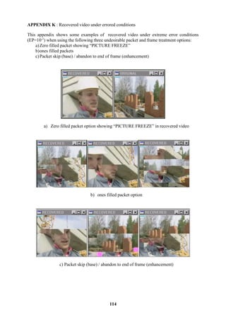

MSC-Thesis-Wireless-Video-over-HIPERLAN2-JustinJohnstone
- 1. DEPARTMENT OF ELECTRICAL AND ELECTRONIC ENGINEERING UNIVERSITY OF BRISTOL ________________________________________ “WIRELESS VIDEO OVER HIPERLAN/2” A THESIS SUBMITTED TO THE UNIVERSITY OF BRISTOL IN ACCORDANCE WITH THE REQUIREMENTS OF THE DEGREE OF M.SC. IN COMMUNICATIONS SYSTEMS AND SIGNAL PROCESSING IN THE FACULTY OF ENGINEERING. ________________________________________ JUSTIN JOHNSTONE OCTOBER 2001
- 3. i ABSTRACT In this report, techniques are investigated to optimise the performance of scalable modes of video coding over a HiperLAN/2 wireless LAN. This report commences with a review of video coding theory and overviews of the H.263+ video coding standard and HiperLAN/2. A review of the nature of errors in wireless environments and how these errors impact the performance of video coding is then presented. Existing packet video techniques are reviewed, and these lead to the proposal of an approach to convey scaled video over HiperLAN/2. The approach is based on the Unequal Packet-Loss Protection (UPP) technique, and it prioritises layered video data into four priority streams, and associates each of these priority streams with an independent HiperLAN/2 connection. Connections are configured to provide increased amounts of protection for higher priority video data. A simulation system is integrated to allow benefits of this UPP approach to be assessed and compared against an Equal Packet-Loss Protection (EPP) scheme, where all video data shares the same HiperLAN/2 connection. Tests conclude that the UPP approach does improve recovered video performance. The case is argued that the UPP approach increases potential capacity offered by HiperLAN/2 to provide multiple simultaneous video services. This combination of improved performance and increased capacity allows the UPP approach to be endorsed. Testing highlighted the video decoder software’s intolerance to data loss or corruption. A number of options to treat errored packets and video frames, prior to passing them to the decoder, are implemented and assessed. Two options which improve recovered video performance are recommended within the context of this project. It is also recommended that the decoder program is modified to improve it’s robustness to data loss/corruption. Error models within the simulation system permitted configuration of bursty errors, and tests illustrate improved video performance under increasingly bursty error conditions. Based on these performance differences, and the fact that bursty errors are more representative of the nature of wireless channels; it is recommended that any future simulations include bursty error models.
- 4. ii ACKNOWLEDGMENTS I would like to thank the following for their support with this project: David Redmill, my project supervisor at Bristol University, for his patient guidance. James Chung-How and David Clewer, research staff within the Centre for Communications Research (CCR) at Bristol University, for their insights and assistance into use of the H.263+ video codec software, and specifically to James for providing the software utility to derive PSNR measurements. Tony Manuel and Richard Davies, technical managers at Lucent Technologies, for allowing me to undertake this MSc course at Bristol University. AUTHOR’S DECLARATION I declare that all the work presented in this report was produced by myself, unless otherwise stated. Recognition is made to my project supervisor, David Redmill, for his guidance. Any use of ideas of other authors has been fully acknowledged by use of references. Signed, Justin Johnstone DISCLAIMER The views and opinions expressed in this report are entirely those of the author and not the University of Bristol.
- 5. iii TABLE OF CONTENTS CHAPTER 1 ...... INTRODUCTION...................................................................................... 1 1.1. Motivation ............................................................................................................... 1 1.2. Scope of Investigations............................................................................................ 2 1.3. Organisation of this Report...................................................................................... 2 CHAPTER 2 ...... REVIEW OF THEORY AND STANDARDS .......................................... 3 2.1. Video Coding Concepts........................................................................................... 3 2.1.1. Digital Capture and Processing..................................................................................................3 2.1.2. Source Picture Format................................................................................................................4 2.1.3. Redundancy and Data Compression ..........................................................................................5 2.1.4. Coding Categories......................................................................................................................8 2.1.5. General Coding Techniques.......................................................................................................8 2.1.5.1. Block Structuring...............................................................................................................8 2.1.5.2. Intraframe and interframe coding.....................................................................................10 2.1.5.2.1. Motion Estimation ........................................................................................................10 2.1.5.2.2. Intraframe Predictive Coding........................................................................................11 2.1.5.2.3. Intra Coding..................................................................................................................12 2.1.6. Quality Assessment..................................................................................................................14 2.1.6.1. Subjective Assessment.....................................................................................................15 2.1.6.2. Objective/Quantitative Assessment..................................................................................15 2.2. Nature of Errors in Wireless Channels.................................................................. 17 2.3. Nature of Packet Errors ......................................................................................... 18 2.4. Impact of Errors on Video Coding ........................................................................ 19 2.5. Standards overview................................................................................................ 20 2.5.1. Selection of H.263+.................................................................................................................20 2.5.2. H.263+ : “Video Coding for Low Bit Rate Communications” ................................................21 2.5.2.1. Overview..........................................................................................................................21 2.5.2.2. SNR scalability ................................................................................................................21 2.5.2.3. Temporal scalability.........................................................................................................22 2.5.2.4. Spatial scalability.............................................................................................................22 2.5.2.5. Test Model Rate Control Methods...................................................................................23 2.5.3. HiperLAN/2.............................................................................................................................23 2.5.3.1. Overview..........................................................................................................................23 2.5.3.2. Physical Layer..................................................................................................................24 2.5.3.2.1. Multiple data rates ........................................................................................................25 2.5.3.2.2. Physical Layer Transmit Sequence ...............................................................................26 2.5.3.3. DLC layer ........................................................................................................................27 2.5.3.3.1. Data transport functions................................................................................................27 2.5.3.3.2. Radio Link Control functions........................................................................................28 2.5.3.4. Convergence Layer (CL)..................................................................................................28 CHAPTER 3 ...... REVIEW OF EXISTING PACKET VIDEO TECHNIQUES................... 29 3.1. Overview ............................................................................................................... 29 3.2. Techniques Considered.......................................................................................... 30 3.2.1. Layered Video and Rate Control .............................................................................................30 3.2.2. Packet sequence numbering and Corrupt/Lost Packet Treatment ............................................32 3.2.3. Link Adaptation .......................................................................................................................33 3.2.4. Intra Replenishment .................................................................................................................35 3.2.5. Adaptive Encoding with feedback ...........................................................................................35 3.2.6. Prioritised Packet Dropping.....................................................................................................36 3.2.7. Automatic Repeat Request and Forward Error Correction ......................................................36 3.2.7.1. Overview..........................................................................................................................36 3.2.7.2. Examples..........................................................................................................................37 3.2.7.2.1. H.263+ FEC..................................................................................................................37 3.2.7.2.2. HiperLAN/2 Error Control ...........................................................................................37 3.2.7.2.3. Reed-Solomon Erasure (RSE) codes ............................................................................39 3.2.7.2.4. Hybrid Delay-Constrained ARQ...................................................................................39 3.2.8. Unequal Packet Loss Protection (UPP) ...................................................................................39
- 6. iv 3.2.9. Improved Synchronisation Codewords (SCW)........................................................................40 3.2.10. Error Resilient Entropy Coding (EREC)..................................................................................41 3.2.11. Two-way Decoding..................................................................................................................41 3.2.12. Error Concealment...................................................................................................................42 3.2.12.1. Repetition of Content from Previous Frame ....................................................................42 3.2.12.2. Content Prediction and Replacement ...............................................................................42 CHAPTER 4 ...... EVALUATION OF TECHNIQUES AND PROPOSED APPROACH .... 43 4.1. General Packet Video Techniques to apply........................................................... 43 4.2. Proposal: Layered video over HiperLAN/2........................................................... 44 4.2.1. Proposal Details.......................................................................................................................45 4.2.2. Support for this approach in the HiperLAN/2 Simulation .......................................................48 CHAPTER 5 ...... TEST SYSTEM IMPLEMENTATION..................................................... 49 5.1. System Overview................................................................................................... 49 5.2. Video Sequences.................................................................................................... 49 5.3. Video Codec .......................................................................................................... 50 5.4. Scaling Function.................................................................................................... 50 5.5. HIPERLAN/2 Simulation System ......................................................................... 51 5.5.1. Existing Simulations ................................................................................................................51 5.5.1.1. Hardware Simulation .......................................................................................................51 5.5.1.2. Software Simulations .......................................................................................................51 5.5.2. Development of Bursty Error Model .......................................................................................51 5.5.3. Hiperlan/2 Simulation Software...............................................................................................53 5.5.3.1. HiperLAN/2 Error Model ................................................................................................53 5.5.3.2. HiperLAN/2 Packet Error Treatment and Reassembly ....................................................53 5.6. Measurement system ............................................................................................. 54 5.7. Proposed Tests....................................................................................................... 54 5.7.1. Test 1: Layered Video with UPP over HiperLAN/2 ................................................................54 5.7.2. Test 2: Errored Packet and Frame Treatment ..........................................................................55 5.7.3. Test 3: Performance under burst and random errors ................................................................56 CHAPTER 6 ...... TEST RESULTS AND DISCUSSION...................................................... 57 6.1. Test 1: Layered Video with UPP over HiperLAN/2.............................................. 57 6.1.1. Results......................................................................................................................................57 6.1.2. Observations and Discussion ...................................................................................................57 6.2. Test 2: Errored packet and frame Treatment ......................................................... 59 6.2.1. Results......................................................................................................................................59 6.2.2. Discussion................................................................................................................................59 6.3. Test 3: Comparison of performance under burst and random errors..................... 60 6.3.1. Results......................................................................................................................................60 6.3.2. Discussion................................................................................................................................60 6.4. Limitations in Testing............................................................................................ 61 CHAPTER 7 ...... CONCLUSIONS AND RECOMMENDATIONS..................................... 62 7.1. Conclusions ........................................................................................................... 62 7.2. Recommendations for Further Work..................................................................... 63 REFERENCES .. .................................................................................................................... 65 APPENDICES ... .................................................................................................................... 67 APPENDIX A : Overview of H263+ Optional Modes................................................... 68 APPENDIX B : Command line syntax for all simulation programs .............................. 69 APPENDIX C : Packetisation and Prioritisation Software – Source code listings........ 71 APPENDIX D : Hiperlan/2 – Analysis of Error Patterns............................................... 77 APPENDIX E : Hiperlan/2 Error Models and Packet Reassembly/Treatment software 78 APPENDIX F : Summary Reports from HiperLAN/2 Simulation modules................ 107 APPENDIX G : PSNR calculation program ................................................................ 110 APPENDIX H : Overview and Sample of Test Execution .......................................... 111
- 7. v APPENDIX I : UPP2 and UPP3 – EP derivation, Performance comparison............... 112 APPENDIX J : Capacities of proposed UPP approach versus non-UPP approach .... 113 APPENDIX K : Recovered video under errored conditions ........................................ 114 APPENDIX L : Electronic copy of project files on CD............................................... 115
- 8. vi LIST OF TABLES Table 2-1 : Source picture format...........................................................................................................................5 Table 2-2 : Redundancy in digital image and video................................................................................................5 Table 2-3 : Compression Considerations................................................................................................................7 Table 2-4 : Video Layer Hierarchy.........................................................................................................................9 Table 2-5 : Distinctions between Intraframe and Interframe coding.....................................................................10 Table 2-6 : Intraframe Predictive Coding .............................................................................................................11 Table 2-7 : Wireless Propagation Issues...............................................................................................................17 Table 2-8 : Impact of Errors in Coded Video ......................................................................................................19 Table 2-9 : HiperLAN/2 Protocol Layers .............................................................................................................24 Table 2-10 : OSI Protocol Layers above HiperLAN/2 .........................................................................................24 Table 2-11 : HiperLAN/2 PHY modes.................................................................................................................25 Table 2-12 : HiperLAN/2 Channel Modes ...........................................................................................................27 Table 2-13 : Radio Link Control Functions..........................................................................................................28 Table 3-1 : General Strategies for Video Coding .................................................................................................29 Table 3-2 : Error Protection Techniques Considered ...........................................................................................30 Table 3-3 : Lost/Corrupt Packet and Frame Treatments Considered....................................................................32 Table 3-4 : Link Adpatation Algorithm – Control Issues .....................................................................................33 Table 3-5 : HiperLAN/2 Error Control Modes for user data ................................................................................38 Table 3-6 : Two-way Decoding ............................................................................................................................42 Table 4-1 : Packet Video Techniques – Extent Considered in Testing.................................................................44 Table 4-2 : Proposed Prioritisation.......................................................................................................................45 Table 4-3 : Default UPP setting for DUC of a point-to-point connection.............................................................45 Table 4-4 : Default UPP setting for DUC of a broadcast downlink connection ...................................................46 Table 4-5 : Default UPP setting for DUC of a point-to-point connection.............................................................48 Table 5-1 : Error Models for Priority Streams......................................................................................................53 Table 5-2 : Packet and frame treatment Options...................................................................................................54 Table 5-3 : Test Configurations For UPP Tests....................................................................................................55 Table 5-4 : Tests for Packet and Frame Treatment...............................................................................................55 Table 5-5 : Common Test Configurations For Packet and Frame Treatment .......................................................56 Table 5-6 : Test for Random and Burst Error Conditions.....................................................................................56 Table 5-7 : Common Test Configurations For Random and Burst Errors ............................................................56 Table 6-1 : Allocation of PHY Modes..................................................................................................................58 LIST OF ILLUSTRATIONS Figure 2-1 : Image Digitisation...............................................................................................................................4 Figure 2-2 : Generic Video System.........................................................................................................................5 Figure 2-3 : Categories of Image and Video Coding .............................................................................................8 Figure 2-4 : Video Layer Decomposition ...............................................................................................................9 Figure 2-5 : Predictive encoding relationship between I-, P- and B- frames ........................................................10 Figure 2-6 : Motion Estimation.............................................................................................................................11 Figure 2-7 : Block Encode/Decode Actions .........................................................................................................12 Figure 2-8 : Transform Coefficient Distribution and Quantisation Matrix ...........................................................13 Figure 2-9 : SNR scalability .................................................................................................................................22 Figure 2-10 : Temporal scalability........................................................................................................................22 Figure 2-11 : Spatial scalability............................................................................................................................23 Figure 2-12 : HiperLAN/2 PHY mode link requirements.....................................................................................25 Figure 2-13 : HiperLAN/2 Physical Layer Transmit Chain..................................................................................26 Figure 2-14 : HiperLAN/2 “Packet” (long PDU) format......................................................................................28 Figure 3-1 : HiperLAN/2 Link Throughput (channel Model A)...........................................................................34 Figure 4-1 : Proposed Admission Control/QoS ....................................................................................................47 Figure 5-1 : Test System Overview ......................................................................................................................49 Figure 5-2 : Burst Error Model.............................................................................................................................52 Figure 5-3 : HiperLAN/2 Simulation....................................................................................................................53 Figure 6-1 : Comparison of EPP with proposed UPP approach over HiperLAN/2. .............................................57 Figure 6-2 : Comparison of Errored Packet and Frame Treatment.......................................................................59 Figure 6-3 : Performance under Random and Burst Error Conditions..................................................................60
- 9. 1 Chapter 1 Introduction 1.1. Motivation There is significant growth today in the area of mobile wireless data connectivity, ranging from home and office networks to public networks, such as the emerging third generation mobile network. In all these areas, there is expectation of an increase in support for multimedia rich services, especially since increased data rates make this more feasible. While there is strong incentive to develop and provide such services, the network owner/operator is faced with many commercial and technical considerations to balance, including the following: Consideration 1. Given a finite radio spectrum resource, there is a need to balance the increasing bandwidth demands of any one single service against the requirement to support as many concurrent services/subscribers as possible without causing network congestion or overload. Consideration 2. The need to cater for user access devices with varying complexities and capabilities (for example, from laptop PCs to PDAs and mobile phones). Consideration 3. The need to support end-to-end services, which may be conveyed across numerous heterogenous networks and technology standards. For example, data originating in a corporate Ethernet network may be sent simultaneously to both: a) a mobile phone across a public mobile network. b) a PC on a home wireless LAN via a broadband internet connection. Consideration 4. The need to provide services which can adapt and compensate for the error characteristics of a wireless mobile environment. Digital video applications are expected to form a part of the increase in multimedia services. Video conferencing is just one example of real-time video applications that places great bandwidth and delay requirement demands on a network. In fact, [21] asserts that most real- time video applications exceed the bandwidth available with existing mobile systems, and that innovations in video source and channel coding are therefore required alongside the advances in radio and air interface technology. Within video compression and coding research, there has been much interest in scalable video coding techniques. Chapter 23 of [21] defines video scalability as “the property of the encoded bitstream that allows it to support various bandwidth constraints or display resolutions”. This facility allows video performance to be optimised depending on both bandwidth availability and decoder capability, albeit at some penalty to compression efficiency. In the case of broadcast transmission over a network, a rate control mechanism can be employed between video encoder and decoder that dynamically adapts to the bandwidth demands on multiple links. The interest in scalable video is clearly justified by the scenario where it is desirable to avoid compromising the quality of decoded video for one user with high bandwidth and high specification user equipment (e.g. a PC via a broadband internet connection), while still providing a reduced quality video to a second user with low bandwidth and low specification equipment (e.g. a mobile phone over a public mobile network). Another illustration of this problem is given in [19], which highlights the similar predicament currently facing the web design community. With the more recent introduction of web-connected platforms, such as PDAs and WAP phones, web designers are now challenged to produce web content which can dynamically cater for varying levels or classes of access device capability (e.g. screen size and processing power). One potential strategy
- 10. 2 identified in [19] echoes the video scalability principle, in that ideally, the means to derive “reduced complexity” content should be embedded within each web page. This would allow web designers to avoid the undesired task of publishing and maintaining multiple sites - each dedicated to the capabilities of each class of access device. With the potential for significant growth in video applications via broadband internet and third generation mobile access, it is therefore inevitable that for the same reason, scalable video will become increasingly important too. 1.2. Scope of Investigations The brief of this project is to focus on optimising aspects of scalable video coding over a wireless LAN, and specifically the HiperLAN/2 standard [2]. Within the HiperLAN/2 standard, a key feature of the physical layer is that it supports a number of different physical modes, which have differing data rates and link quality requirements. Specifically, the modes with higher nominal data rates require higher carrier-to-interference (C/I) levels to be able to achieve near their nominal data rates. Performance studies ([7],[16],[20]) have shown that as the C/I decreases, higher overall throughput can be maintained if the physical mode is reduced at specific threshold points. The responsibility to monitor and dynamically alter physical modes is designated to a function referred to as “link adaptation”. However, as this is function is not defined as part of the HiperLAN/2 standard, there is interest to propose algorithms in this area. This project was tasked to recommend an optimal scheme to convey layered video data over HiperLAN/2, including assessment of link adaptation algorithms. However, when making proposals in any one specific area of mobile multimedia applications, it is vital to consider these in the wider context of the entire system in which they will operate. Therefore this report also considers many of the more general techniques in the area of “wireless packet video”. 1.3. Organisation of this Report The remainder of this report is organised as follows: Chapter 2 commences with an introduction of video coding theory. It then provides an overview of nature of errors in a wireless environment, and what effect these have on the performance of video coding. Chapter 2 concludes with an overview of the standards used in the project, namely H.263+ and HiperLAN/2. Chapter 3 presents a review of some existing wireless packet video techniques, which are considered for investigation in this project. Chapter 4 proposes the approach intended to convey layered video bitstream over HiperLAN/2. The chapter also considers which of the more general techniques to apply during testing. Chapter 5 describes the implementation of components in the simulation system used for investigations, and then introduces the specific tests to be conducted. Chapter 6 discusses test results, and chapter 7 presents conclusions, including a list of areas identified for further investigation.
- 11. 3 Chapter 2 Review of Theory and Standards This chapter introduces some useful concepts regarding video coding, wireless channel errors and their effect on coded video. The chapter concludes with an overview of the standards used in the project; H.263+ and HiperLAN/2. 2.1. Video Coding Concepts The following basic concepts are discussed in this section: Digital image capture and processing considerations Picture Formats Redundancy and Compression Video Coding Techniques Quality assessment The video coding standards considered for use on this project include H.263+, MPEG-2 and MPEG-4, since all these standards incorporate scalability. While the basic concepts discussed in this section are common to all these standards, many of the illustrations are tailored to highlight specific details of H.263+, since this is the standard selected for use in this project. Further details of this standard, including it scalability modes, are discussed later in section 2.5.1. 2.1.1. Digital Capture and Processing Digital images provide a two dimensional representation of the visual perception of the three- dimensional world. As indicated in [22], the process to produce digital images involves the following two stages, shown also in Figure 2-1 below: Sampling: Here an image is partitioned into a grid of discrete regions called picture elements (abbreviated “pixels” or “pels”). An image capture device obtains measurements for each pixel. Typically this is performed by a scan, which commences in one corner of the grid, and proceeds sequentially row by row, and pixel by pixel within each row, until measurements for the last pixel, in the diagonally opposite corner to the start point are recorded. Commonly, image capture devices record the colour components for each pixel in RGB colour format. Quantisation: Measured values for each pixel are mapped to the nearest integer within a given range (typically this range is 0 to 255). In this way, digitisation results in an image being represented by an array of integers. Note:. The RGB representation is typically converted into YUV format (where Y represents luminance and U,V represent chrominance values). The significant benefit of this conversion is that it subsequently allows more efficient coding of the data.
- 12. 4 Figure 2-1 : Image Digitisation Digital video is a sequence of still images (or frames) displayed sequentially at a given rate, measured in frames per second (fps). When designing a video system, trade-off decisions need to be made between the perceived visual quality of the video and the complexity of the system, which may typically be characterised by a combination of the following: Storage Space/cost Bandwidth Requirements (i.e. data rate required for transmission) Processing power/cost. These trade-off decision can be partly made by defining the following parameters of the system. Note that increasing these parameters enhances visual quality at the expense of increased complexity. Resolution: This includes both: The number of chrominance/luminance samples in horizontal and vertical axes. The number of quantised steps in the range of chrominance and luminance values (for example, whether 8, 16 or more bits are stored for each value). Frame rate: The number of frames displayed per second. Sensitivity limitations of the Human Visual System (HVS) effectively establish practical upper thresholds for the above parameters, beyond which there are diminishing returns in perceived quality. An example of video coding adapting to the HVS limits is the technique known as “chrominance sub-sampling”. Here, the number of chrominance samples is reduced by a given factor (typically 2) relative to the number of luminance samples in one or both of the horizontal and vertical axes. The justification for this is that the HVS is spatially less sensitive to differences in colour than brightness. 2.1.2. Source Picture Format Common settings for resolution parameters have been defined within video standards. One example is the “Common Intermediate Format” (CIF) picture format. The parameters for CIF are shown in Table 2-1 below, along with some common variants.
- 13. 5 Table 2-1 : Source picture format Source Picture Format Resolution (Number of samples in horizontal x vertical) Luminance Chrominance 16CIF 1408x1152 704x576 4CIF 704x576 352x288 CIF 352 x 288 176 x 144 QCIF (Quarter-CIF) 176 x 144 88 x 72 sub-QCIF 128x96 64x48 2.1.3. Redundancy and Data Compression Even with fixed setting for resolution and frame rate parameters, it is both desirable and possible to further reduce the complexity of the video system. Significant reductions in storage or bandwidth requirements may be achieved by encoding and decoding of the video data to achieve data compression. A generic video coding scheme depicting this compression is shown in Figure 2-2 below. reference input video recovered output video transmission channel or data storage Video Encoder compressed data compressed data Video Decoder Figure 2-2 : Generic Video System Data compression is possible, since video data contains redundant information. Table 2-2 lists the types of redundancy and introduces two compression techniques which take advantage of this redundancy. These techniques are discussed later in section 2.1.5. Table 2-2 : Redundancy in digital image and video Domain where Redundancy Exists Description Applicable Compression Technique Spatial: Within a typical still image, spatial redundancy exists in a uniform region of the image, where luminance and chrominance values are highly correlated between neighbouring samples. Intraframe Predictive coding Temporal: Video contains temporal redundancy in that data in one frame is often highly correlated with data in the same region of the subsequent frame (e.g. where the same object appears in the subsequent frames, albeit with some motion effects). This correlation diminishes as the frame rate is reduced and/or the motion content within the video sequence increases. Interframe Predictive coding.
- 14. 6 While the encoding and decoding procedures do increase processing demands on the system, this penalty is often accepted when compared to the potential savings in storage and bandwidth costs. Apart from increased processing power, there are other options to consider during compression. These generally trade-off compression efficiency against perceived visual quality, as shown in Table 2-3 below.
- 15. 7 Table 2-3 : Compression Considerations Consideration Factor Effects on: Compression Efficiency Perceived Quality a) Resolution, Frame Rate Skipping frames/ reducing the frames rate will increase efficiency. Digitising the same picture with an increased number of pixels allows that more spatial correlation and redundancy can be exploited during compression. Increased resolution (e.g. going from 8 to 16 bit representation) will decrease efficiency. Increases in resolution and frame rate typically improve quality at the expense of increased processing complexity/cost. b) Latency: end-to-end delays introduced into the system due to finite processing delays. Improved compression may improve or degrade latency, dependant on other system features. At one extreme, it may increase latency due to increased complexity and therefore increased processing delays. At the other extreme, in a network, it may result in a reduced bandwidth demand. This may serve to reduce network load and actually reduce buffering delays and latency in the network. If frames are not played back at a regular frame rate, the resultant pausing or skipping will drastically reduce perceived quality. c) Lossless compression: where the original can be reconstructed exactly after decompression. This category of compression typically achieves lower compression efficiency than lossless compression. By definition, the recovered image is not degraded. This may be more applicable to medical imaging or legal applications where storage costs or latency are of less concern. d) Lossy compression: where the original cannot be reconstructed exactly. This typically achieves higher compression efficiency than lossless. By definition, the quality will be degraded, however techniques here may capitalise on HVS limitations, so that the losses are less perceivable. This is more applicable to consumer video applications.
- 16. 8 2.1.4. Coding Categories There is a wide selection of strategies for video coding. The general categories into which these strategies are allocated is shown in Figure 2-3 below. As indicated by the shading in the diagram, this project makes use of DCT transform coding, which is categorised as a lossy, waveform based method. Categories of Image and Video Coding MODEL based WAVEFORM based Statistical Universal Spatial Frequency LossyLoss-less example: - wire frame modelling examples: - sub-band examples: - fractal - predicitive(DPCM) example: - ZIP examples: - Huffman - Arithmetic - DCT transform Note: shaded selections identify the categories and method considered in this project. Figure 2-3 : Categories of Image and Video Coding 2.1.5. General Coding Techniques To achieve compression, a video encoder typically performs a combination of the following techniques, which are discussed briefly in the sub-sections below this list: Block Structure and Video Layer Decomposition Intra and Inter coding: Intraframe prediction, Motion Estimation Block Coding: Transform, Quantisation and Entropy Coding. 2.1.5.1. Block Structuring The raw array of data samples produced by digitisation is typically restructured into a format that the video codec can take advantage of during processing. This new structure typically consists of a four layer hierarchy of sub-elements. A graphical view of this decomposition of layers, with specific values for QCIF and H.263+ is given in Figure 2-4 below. When coding schemes apply this style of layering, with the lowest layer consisting of blocks, the coding scheme is said to be “block-based” or “block-structured”. Alternatives to block-based coding are object- and model-based coding. While these alternatives promise the potential for even lower bit rates, they are less mature than current block-based techniques. These will not be covered in this report, however more information can be found in chapter 19 of [21].
- 17. 9 Figure 2-4 : Video Layer Decomposition A brief description of the contents of these four layers is given in Table 2-4 below. Some of the terms introduced in this table are be covered later. Table 2-4 : Video Layer Hierarchy Layer Description/Contents a) Picture: This layer commences each frame in the sequence, and includes: Picture Start Code. Frame number. Picture type, which is very important as it indicates how to interpret subsequent information in the sub-layers. b) Group of blocks (GOB): GOB start code. Group number. Quantisation information. c) MacroBlock (MB): MB address. Type (indicates intra/inter coding, use of motion compensation). Quantisation information. Motion vector information. Coded Block Pattern. d) Block: Transform Coefficients. Quantiser Reconstruction Information.
- 18. 10 2.1.5.2. Intraframe and interframe coding The features and main distinctions between these two types of coding is summarised briefly in Table 2-5 below. Table 2-5 : Distinctions between Intraframe and Interframe coding Coding Style Features and Implications INTER coding Frames coded this way rely on information in previous frames, and code the relative changes from this reference frame. This coding improves compression efficiency (compared to intra coding). The decoder is only able to reconstruct an inter coded frame when it has received both: a) the reference frame, and b) the inter frame. The common type of inter coding, relevant to project, is ‘Motion Estimation and Compensation’, which is discussed below. The reference frame(s) can be forward or backwards in time (or a combination of both) relative to the predictive encoded frame. When the reference frame is a previous frame, the encoded frame is called a “P-frame”. When reference frames are previous and subsequent frames, the encoded frame is termed a “B-frame” (Bi-directional). This relationship is made clear in Figure 2-5 below. Since decoding depends on data in reference frames, any errors that occur in the reference will persist and propagate into subsequent frames – this is known as “temporal error propagation”. INTRA coding Does not rely on previous (or subsequent) frames in the video sequence. Compression efficiency is reduced (compared to inter coding). Recovered video quality is improved. Specifically, if any temporal error propagation existed, it will be removed at the point of receiving the intra coded frame. Frames coded this way are termed “I-frames”. I-frame I-frame P-frame B-frame P-frame B-frame Forward Prediction from Reference Bi-Directional Prediction from References time Figure 2-5 : Predictive encoding relationship between I-, P- and B- frames 2.1.5.2.1. Motion Estimation Motion estimation and compensation techniques provide data compression by exploiting temporal redundancy in a sequence of frames. “Block Matching Motion Estimation” is one such technique, which results in a high levels of data compression.
- 19. 11 The essence of this technique is that for each macroblock in the current frame, an attempt is made to locate a matching macroblock within a limited search window in the previous frame. If a matching block is found, the relative spatial displacement of the macroblock between frames is determined, and this is coded and sent as a motion vector. This is shown in Figure 2-6 below. Transmitting the motion vector instead of the entire block represents a vastly reduced amount of data. When no matching block is found, then the block will need to be intra coded. Limitations of this technique include the following: It does not cater for three dimensional aspects such as zooming, object rotation and object hiding. It suffers from temporal error propagation. matched MB n (x+ Dx, y+Dy) Macroblock n position in previous frame (x,y) Macroblock n position in current frame MB n (Dx, Dy) motion vector for MB n search window - vertical search range search window - horizontal search range Figure 2-6 : Motion Estimation 2.1.5.2.2. Intraframe Predictive Coding This technique provides compression by taking advantage of the spatial redundancy within a frame. This technique operates by performing the sequence of actions at the encoder and decoder as listed in Table 2-6 below. Table 2-6 : Intraframe Predictive Coding Actions performed by: Actions for each sample: 1. Encoder: a) An estimate for the value of the current sample is produced by a prediction algorithm that uses values from ‘neighbouring” samples. b) The difference (or error term) between the actual and the predicted values is calculated. c) The error term is sent to the decoder (see notes 1 and 2 below). 2. Decoder: a) The same prediction algorithm is performed to produce an estimate for the current sample. b) This estimate is adjusted by the error term received from the encoder to produce an improved approximation of the original sample.
- 20. 12 Notes: 1) For highly correlated samples in a uniform region of the frame, the prediction will be very precise, resulting in a small or zero error term, which can be coded efficiently. 2) When edges occur between non-uniform regions within an image, neighbouring samples will be uncorrelated and the prediction will produce a large error term, which diminishes coding efficiency. However, chapter 2 of [23] highlights the following two factors which determine that this technique does provide overall compression benefits: a) Within a wide variety of naturally occurring image data, the vast majority of error terms are very close to zero – hence on average, it is possible to code error terms efficiently. b) While the HVS is very sensitive to the location of edges, it is not as sensitive the actual magnitude change. This allows that the large magnitude error terms can be quantised coarsely, and hence coded more efficiently. 3) Since this technique only operates on elements within the same frame, the “intraframe” aspect of it’s name is consistent with the definitions in Table 2-5. However, since coded data depends on previous samples, it is subject to error propagation in a similar way to interframe coding. This error propagation may manifest itself as horizontal and/or vertical streaks to the end of a row or column. 2.1.5.2.3. Intra Coding When a block is intra coded (for example, when a motion vector cannot be used), the encoder translates the data in the block into a more compact representation before transmitting it to the decoder. The objective of such translation (from chapter 3 of [23]) is: “to alter the distribution of the values representing the luminance levels so that many of them can either be deleted entirely, or at worst be quantised with very few bits”. The decoder must perform the inverse of the translation actions to restore the block back to the original raw format. If the coding method is categorised as being loss-less, then the decoder will be able to reconstruct the original data exactly. However, this project makes use of lossy a coding method, where a proportion of the data is permanently lost during coding. This restricts the decoder to reconstruct an approximation of the original data. The generic sequence of actions involved in block encoding and decoding are shown in Figure 2-7 below. Each of these actions is discussed in the paragraphs below, which also introduce some specific examples relevant to this project. Transform block (e.g. 8x8) Entropy Code Quantise Inverse Transform Requantise transmission channel or storage Entropy Decode ENCODER block (e.g. 8x8) DECODER Figure 2-7 : Block Encode/Decode Actions
- 21. 13 Transformation This involves translation of the sampled data values in a block into another domain. In the original format, samples may be viewed as being in the spatial domain. However, chapter 3 of [23] indicates these may equally be considered to be in the temporal domain, since the scanning process during image capture provides a deterministic mapping between the two domains. The coding category highlighted in Figure 2-3 for use in this project is “Waveform/Lossy/Frequency”. The frequency aspect refers to the target domain for the transform. The transform can be therefore be viewed as a time to frequency domain transform, allowing selection of a suitable Fourier Transform based method. Possibilities for this include: Walsh-Hadamard Transform (WDT) Discrete Cosine Transform (DCT) Karhunen-Loeve Transform (KLT) The DCT is a popular choice for many standards, including JPEG and H.263. The output of the transform on an 8x8 (for example) block results in the same number (64) of transform coefficients, each representing the magnitude of frequency component. The coefficients are arranged in the block with the single DC coefficient in the upper left corner, then zig-zag along diagonals with the highest frequency coefficient in the lower right corner of the block (see Figure 2-8). Since the transform produces the same number of coefficients as there were to start with; it does not directly achieve any compression. However, compression is achieved in the subsequent step, namely quantisation. Further details of the DCT transform are not presented here, as these are not directly relevant to this project, however [23] may be referred to for more details. Quantisation This operation is performed on the transform coefficients. These coefficients usually have widely varying range of magnitudes, with a typical distribution as shown in the left side of Figure 2-8 below. This distribution makes it possible to ignore some of the coefficients with sufficiently small magnitudes. This is achieved by applying a variable quantisation step size to positions in the block, as shown in the right side of Figure 2-8 below. This approach provides highest resolution to the DC and high magnitude coefficients in the top left of the block, while reducing resolution toward the lower right corner of the block. The output of the quantisation typically results in a block with some non-zero values towards the upper left of the block, but many zeros towards the lower right corner of the block. Compression is achieved when these small or zero magnitude values are coded more efficiently as seen in the subsequent step, namely Entropy Coding. DC large magnitude low frequency coefficients small magnitude high frequency coefficients 8x8 block of transform coefficients smallest quantistion values - better resolution largest quantisation values, lowest resolution corresponding 8x8 matrix of quantisation coefficients increasing quantisation values increasing quantisation values coefficients loaded diagnoanally Figure 2-8 : Transform Coefficient Distribution and Quantisation Matrix
- 22. 14 Entropy Coding This type of source coding provides data compression without loss of information. In general, source coding schemes map each source symbol to a unique (typically binary) codeword prior to transmission. Compression is achieved by coding as efficiently as possible (i.e. using the fewest number of bits). Entropy coding achieves efficient coding by using variable length codewords. Shorter codewords are assigned to those symbols that occur more often, and longer codewords are assigned to symbols that occur less often. This means that on average, shorter codewords will be used more often, resulting in fewer bits being required to represent an average sequence of source symbols. An optional, but desirable property for variable length codes is the “prefix-free” property. This property is satisfied when no codeword is the prefix of any other codeword. This has the benefit that codewords are “instantaneously decodable”, which implies that the end of a codeword can be determined as the codeword is read (and without the need to receive the start of the next codeword). Unfortunately, there are also some drawbacks in using variable length codes. These include: 1) The instantaneous rate at which codewords are received will vary due to the variable codeword length. A decoder therefore requires buffering to smooth the rate at which codewords are received. 2) Upon receipt of a corrupt codeword, the decoder may lose track of the boundaries between codewords. This can result in the following two undesirable outcomes, which are relevant as their occurrence is evident later in this report: a) The decoder may only recognise the existence of an invalid codeword sometime after it has read beyond the start of subsequent codewords. In this way, a number of valid codewords may be incorrectly ignored until the decoder is able to resynchronise itself to the boundaries of valid codewords. b) When attempting to resynchronise, a “false synchronisation” may occur. This will result in further loss of valid codewords until the decoder detects this condition and is able to establish valid resynchronisation. An example of a prefix-free variable length code is the Huffman Code. This has the advantage that it “can achieve the shortest average code length” (chapter 11 of [24]). Further details of Huffman coding are not covered here, as they are not of specific interest to this project. Within a coded block of data, it common to observe a sequence of repeated data values. For example, the quantised transform coefficients near the lower right corner of the block are often reduced to zero. In this case, it is possible to modify and further improve the compression efficiency of Huffman (or other source) coding, by applying “Run-Length coding”. Instead of encoding each symbol in a lengthy run of repeated values, this technique describes the run with an efficient substitution code. This substitution code typically consists of a control code and a repetition count to allow the decoder to recreate the sequence exactly. 2.1.6. Quality Assessment When developing video coding systems, it is necessary to provide an assessment of the quality of the recovered decoded video. Such assessments provide performance indicators which are necessary to optimise system performance during development or even to confirm the viability of the system prior to deployment. It is usually desirable to perform subjective and quantitative assessments of video performance. It is quite common to perform quantitative assessments during earlier development and optimisation phases, and then to
- 23. 15 conduct subjective testing prior to deployment. Features of these two types of assessment are discussed below. 2.1.6.1. Subjective Assessment Testing is performed by conducting formal human observation trials with a statistically significant population of the target audience for the video application. During the trials, observers independently view video sequences and then rate their opinion of the quality according to a standardised five point scoring system. Scores from all observers are then averaged to provide a “Mean Opinion Score” (MOS) for each video sequence. A significant advantage of subjective assessment trials is that they allows observers to consider the entire range of psycho-visual impressions when rating a test sequence. Trial results therefore reflect a full consideration of all aspects of video quality. MOS scores are therefore a well accepted means to compare the relative performance of different systems. The following implications of subjective assessments are noted: Formal trials are relatively costly and time consuming. This can result in trials being skipped or deferred to later stages of system development. Performance of the same system can vary widely depending on the specific video content used in trials. In the same way, observers’ perceptions are equally dependent on the video content. Therefore, comparison of MOS scores between different systems is only credible if identical video sequences are used. Observers’ perceptions may vary dependant on the context of the environment in which they are viewed. An illustration of this is given in mobile telephony. Here, lower MOS scores for the audio quality of mobile telephony (when compared to higher MOS scores for the quality of PSTN) are tolerated when taking into account the benefits of mobility. This tolerant attitude is likely to persist toward video services offered over mobile networks. Therefore, observation trials should account for this attitude when conducting trials and reporting MOS scores. Alongside the anticipated rapid growth in mobile video services, it is likely that audience expectations will rapidly become more sophisticated. It is therefore suggested that comparing results between two trials is less meaningful if the trial dates are separated by a significant time period (say 2 years, for example). 2.1.6.2. Objective/Quantitative Assessment In strong contrast to subjective testing, where consideration of all aspects of the quality are incorporated within a MOS score; quantitative assessments are able to focus on specific aspects of video quality. It is therefore often more useful if these assessments are quoted in the context of some other relevant parameters (such as frame rate or channel error rate). The defacto measurement used in video research is Peak-Signal-to-Noise Ratio (PSNR), described below. Peak-Signal-to-Noise Ratio (PSNR) This assessment provides a measure in decibels of the difference between original and reconstructed pixels over a frame. It is common to quote PSNR for luminance values only, even though PSNR can be derived for chrominance values as well. This project adopts the convention of using luminance PSNR only. The luminance PSNR for a single frame is calculated according to equation (2) below.
- 24. 16 MSE PSNR frame 2 MAX_LEVEL 10log10 (2) Where, MAX_LEVEL= The maximum value luminance (when using 8 bit representation for luminance, this value is 255) MSE = “Mean Squared Error” of decoded pixel luminance amplitude compared with original reference pixel, given by equation (3) 2 ValuePixelOrignalValuePixelRecovered 1 pixelsNpixelsN MSE (3) Where, Npixels = Total number of pixels in the frame. PSNR may be also be calculated for an entire video sequence. This is simply an average of PSNR values for each frame, as shown in equation (4) below. framesAll frame frames sequence PSNR N PSNR 1 (4) Where, N frames = Total number of decoded frames in sequence. For example, if only frame numbers 1, 6 and 10 are decoded, then N frames = 3. The following implications of using PSNR as a quality assessment are noted: 1. PSNR for a sequence can only be based on the subset of original frames that are decoded. When compression results in frames being dropped, this will not be reflected in the PSNR result. This is a case where quoting the frame rate alongside PSNR results is appropriate. 2. The PSNR calculation requires a reference of the original input video is required at the receiver. This may only be possible in a controlled test environment. 3. PSNR is measured between the original (uncompressed) frames and the final decoded output frames. This therefore reflects a measure of effects across the entire system, including the transmission channel, which may introduce errors. Hence quoting the error rate of the channel alongside the PSNR result may be appropriate in this case 4. Since both: a) PSNRframe is averaged over the pixels in a frame b) PSNRsequence is averaged over the frames in a sequence, these averages are unable to highlight the occurrence of localised quality degradations which may be intolerable to a viewer. Based on this, it is highly recommended that when quoting PSNR measurement, observations from informal (as a minimum) viewing trials are noted as well.
- 25. 17 2.2. Nature of Errors in Wireless Channels Errors in wireless channels result from propagation issues described briefly in Table 2-7 below. Table 2-7 : Wireless Propagation Issues Propagation Issue Description, Implications 1) Attenuation For a line of sight (LOS) radio transmission, the signal power at the receiver will be attenuated due to “free space attenuation loss”, which is inversely proportional to square of the range between transmitter and receiver. For non-LOS transmissions, the signal power will also suffer “penetration losses” when entering or passing through objects. a) Multipath & Shadowing In a mobile wireless environment, transmitted signals will undergo effects such as reflection, absorption, diffraction and scattering off large objects in the environment (such as buildings or hills). Apart from further attenuating the signal, these effects result in multiple versions of the signal being observed at the receiver. This is termed multipath propagation. When the LOS signal component is lost, the effect on received signal power is determined by combination of these multipath signals. Severe power fluctuations at the mobile receiver result as it moves in relation to objects in the environment. The rate of these power fluctuations is limited by mobile speeds in relation to these objects, and is typically less than two per second. For this reason, this power variation is termed “slow fading”. Another type of signal fluctuation exists and this is termed “fast fading”. Due to the differing path lengths of the multipath signals; these signals possess different amplitudes and phases. These will result in constructive or destructive interference when combined instantaneously at the receiver. Minor changes in the environment or very small movements of the mobile receiver can dynamically modify these multipath properties, and this results in rapid fluctuations (above 50Hz, for example) of received signal power – hence the name “fast fading”. As slow and fast fading are occur at the same time, their effects on received power level are superimposed. During fades, received power levels can drops by tens of dB, which can drastically impair system performance. b) Delay Spread Another multipath effect is “delay dispersion”. Due to the varying paths lengths of the versions of the signal, these will arrive at slightly differing times at the receiver. If the delay spread is larger than a symbol period of the system, energy from one symbol will be received during the next symbol period, and this will interfere with the interpretation of that symbol’s true value. This undesirable phenomenon is termed Inter-Symbol Interference (ISI). c) Doppler effects When a mobile receiver moves within the reception area, the phase at the receiver will constantly change due to changing path length. This phase change represents a frequency, known as the Doppler Frequency. At the receiver, unless the offset of the Doppler frequency is tracked, this reduces the energy received over a symbol period, which degrades system performance.
- 26. 18 The combination of these effects, but specifically multipath, results in received signal strength undergoing continual fades of varying depth and duration. When the received signal falls below a given threshold during a fade, then unrecoverable errors will occur at the receiver until the received signal level exceeds the threshold again. Errors therefore occur in bursts over the duration of such fades. This bursty nature of the errors in a wireless is the key point raised in this section. Therefore, when simulating errors in a wireless transmission channel, it is realistic to represent this by a bursty error model (as opposed to a random error model). 2.3. Nature of Packet Errors Degradation of coded video in a packet network can be attributed to the following factors: a) Packet Delay: Whether overall packet delay is a problem depends on the application. One-way, non-interactive services such as video streaming or broadcast can typically withstand greater overall delay. However, two- way, interactive services such as video conferencing are adversely effected by overall delay. Excessive delay can result in effective packet loss, where, for example, if a packet arrives beyond a cut-off time for the decoder to make use of the packet, it is discarded. b) Packet Jitter: This relates to the amount of variation of delay. Jitter may be caused by varying queuing delays at each node across a network. Different prioritisation strategies for packets queues can have significant effects on delay, especially as network congestion increases. The effects of jitter depend on the applications, as before. One-way, non-interactive applications can cope as long as sufficient buffering exists to smooth the variable arrival rate of packets, so that the application can consume packets at a regular rate. Problems still exist for two-way, interactive services when excessive delays result in effective packet loss. c) Packet Loss: Corrupt packets will be abandoned as soon as they are detected in the network. Some queuing strategies can also discard valid packets if they are noted as being “older” than a specified temporal threshold. Since these packets are too late to be of use, there is no benefit in forwarding them. This technique can actually alleviate congestion in networks and reduce overall delays. The fact that an entire packet is lost (even if only a single bit in it was corrupt), further contributes to the bursty nature of errors already mentioned for wireless channels.
- 27. 19 2.4. Impact of Errors on Video Coding Chapter 27 of [21] provides a good illustration of the potentially drastic impact of errors in a video bitstream. Table 2-8 provides a summary of these impacts, showing the type of error and it’s severity. When error propagation results, the table categorises the type of propagation and lists some typical means to reduce the extent of the propagation. The examples in this table are ordered from lowest to highest severity impact. Table 2-8 : Impact of Errors in Coded Video Example 1: Location of error: Within a macroblock of an I-frame, which is not used as a reference in motion estimation. Extent of impact: The error is limited to a (macro)block within one frame only – there is no propagation to subsequent frames. This therefore results in a single block error. Severity: Low Error Propagation Category: Not applicable – no propagation Example 2: Location of error: In motion vectors of a P-frame, that does not cause loss of synchronisation. Extent of impact: Temporal error propagation results, with multiple block errors in subsequent frames until the next intra coded frame is received. Severity: Medium Error Propagation Category: Predictive Propagation Propagation Reduction strategy: The accepted recovery method is to send an intra coded frame to the decoder. Example 3: Location of error: In a variable length codeword of a block which is used for motion estimation, and causes loss of synchronisation. Extent of impact: When the decoder loses synchronisation, it will ignore valid data until it is able to recognise the next synchronisation pattern. If only one synch pattern is used per frame, the rest of the frame may be lost. If the error occurred at the start of an I- frame, not only is this frame lost, but subsequent P-frames will also be severely errored, due to temporal propagation. This potentially results in multiple frame errors. Severity: High Error Propagation Category: Loss of Synchronisation Propagation Reduction strategy: One way to reduce the extent of this propagation, is to insert more synchronisation codewords into the bitstream so that less data is lost before resynchronisation is gained. This has the drawback of increasing redundancy overheads.
- 28. 20 Example 4: Location of error: In the header of a frame. Extent of impact: Information in the header of a frame contains important information about how data is interpreted in the remainder of the frame. If this information is corrupt, data in the rest of the frame is meaningless – hence the entire frame can be lost. Severity: High Error Propagation Category: Catastrophic Propagation Reduction strategy: Protect the header by a powerful channel code to ensure it is received intact. Fortunately, header information represents a small percentage of the bitstream, so the overhead associated with protecting it is less onerous than might be expected. Based on the potentially dramatic impact of these errors, it is evident that additional techniques are required to protect against these errors and their effects in order to enhance the robustness of coded video. Examples of such techniques are discussed in chapter 3. 2.5. Standards overview 2.5.1. Selection of H.263+ H.263+ was selected as the video coding standard for use on this project. Justifications for choosing H.263+ in preference to MPEG include the following: H.263+ simulation software is more readily available and mature than MPEG software. Specifically, an H.263+ software codec [3] is available within the department, and there are research staff familiar with this software. The H263+ specification is much more concise than the MPEG specifications, and given the timeframe of this project, it was considered more feasible to work with this smaller standard. H.263+ is focussed at lower bit rates, which is of more interest in this project. This focus is based on the anticipation of significant growth in video applications being provided over the internet and public mobile networks. To make maximum use of their bandwidth investments, mobile network operators will be challenged to provide services at lower bit rates. Based on this choice, some unique aspects of MPEG-2 and MPEG-4, such as those listed below, are not covered in this project: Fine-Grained-Scalability (FGS). Higher bit rates (MPEG-2 operates from 2 to 30Mbps). Content based scalability (MPEG-4). Coding of natural and synthetic scenes (MPEG-4)
- 29. 21 2.5.2. H.263+ : “Video Coding for Low Bit Rate Communications” 2.5.2.1. Overview H.263+ refers to the version 2 issue of the original H.263 standard. This specification defines the coded representation and syntax for compressed video bitstream. The coding method is block-based and uses motion compensation, inter picture prediction, DCT transform coding, quantisation and entropy coding, as discussed earlier in Chapter 2. The standard specifies operation with all five picture formats listed in Table 2-1, namely sub-QCIF, QCIF, CIF, 4CIF and 16CIF. The specification defines the syntax in the four layer hierarchy (Picture, GOB, MacroBlock and Block) as discussed earlier. The specification defines sixteen negotiable coding modes in a number of annexes. A brief description of all these modes is given in Appendix A. However, the most significant mode for this project is given in annex O, which defines the three scalability modes supported by the standard. With scalability enabled, the coded bitstream is arranged into a number of layers, starting with a mandatory base layer and one or more enhancement layers, as follows: Base Layer A single base layer is coded which contains the most important information in the video bitstream. It is essential for this layer to be sent to the decoder as it contains what is considered as the ‘bare minimum’ amount of information required for the decoder to produce acceptable quality recovered video. This layer consists of I- frames and P-frames. Enhancement Layer(s) One or more enhancement layers are coded above the base layer. These contain additional information, which, if received by the decoder, serve to improve the perceived quality of the recovered video produced by the decoder. Each layer can only be used by the decoder if all layers below it have been received. The lower layer thus forms a reference layer for the layer above it. The modes of scalability relate directly to the way in which they improve the perceived quality of the recovered video, namely: resolution, spatial quality or temporal quality. These modes are described in the following sections. Note that it is possible to combine the scalability modes into a hybrid scheme, although this is not considered in this report. 2.5.2.2. SNR scalability The perceived quality improvement derived from the enhancement layers in this mode is pixel resolution (luminance and chrominance). This mode provides “coding error” information in the enhancement layer(s). The decoder uses this information in combination with that received in the base layer. After decoding information in the base layer to produce estimated luminance and chrominance value for each pixel, the coding error is then used to adjust these values to create a more accurate approximation of the original values. Frames in the enhancement layer are called Enhancement I-frames (EI) and Enhancement P-frames (EP). The “prediction direction” relationship between I and P frames is carried over to the EI and EP frames in the enhancement layer. This relationship is shown in Figure 2-9 below.
- 30. 22 EI EP EP EP I P P P SNR scaled sequence Enhancement Layer 1 BASE layer key: direction of prediction Figure 2-9 : SNR scalability 2.5.2.3. Temporal scalability The perceived quality improvement derived from the enhancement layers in this mode is frame rate. This mode provides the addition of B frames, which are bi-directionally predicted and inserted between I and P frames. These additional frames increase the decoded frame rate, as shown in Figure 2-10 below. I P P P B B B Temporal scalability key: direction of prediction enhancement layer: base layer: Figure 2-10 : Temporal scalability 2.5.2.4. Spatial scalability The perceived quality improvement factor derived from the enhancement layers in this mode is picture size. In this mode, the base layer codes the frame in a reduced size picture format (or equivalently, a reduced resolution at the same picture format size). The enhancement layer contains information to increase the picture to its original size (or resolution). Similar to the SNR scalability, the enhancement layer contains EI and EP frames with the same prediction relationship between them, as shown in Figure 2-11 below.
- 31. 23 EI I P P Spatial Scalability Enhancement Layer (e.g. CIF) BASE layer (e.g. QCIF) EP EP key: direction of prediction Figure 2-11 : Spatial scalability 2.5.2.5. Test Model Rate Control Methods [6] highlights the existence of a rate control algorithm called TMN-8, which is described in [27]. Although not an integral part of the H.263+ standard, this algorithm is mentioned here as it is incorporated within the video encoder software used on this project. TMN-8 controls the dynamic output bit rate of the encoder according to a specified target bit rate. It achieves this by adjusting the macroblock quantisation coefficients. Larger coefficients will reduce the bit rate and smaller coefficients will increase the bit rate. 2.5.3. HiperLAN/2 This section presents a brief overview of the HiperLAN/2 standard, and is largely based on [15]. 2.5.3.1. Overview HiperLAN/2 is an ETSI standard (see [2], [15] and [26]) defining a high speed radio communication system with typical data rates between 6 to 54 Mbit/s, operating in the 5 GHz frequency range. It connects portable devices, referred to as Mobile Terminals (MTs), via a base station, referred to as an Access Point (AP), with broadband networks based on IP, ATM or other technologies. HiperLAN/2 supports restricted user mobility, and is capable of supporting multimedia applications. A HiperLAN/2 network may operate in one of the two modes listed below. The first mode is more typical for business environments, whereas the second mode is more appropriate for home networks: a) “CENTRALISED mode”: where a one or more fixed location APs are configured to provide a cellular access network to a number MTs operating within the coverage area. All traffic passes through an AP either to an external core network or to another MT within the coverage area. b) “DIRECT mode”: where MTs communicate directly with one another in an ad-hoc manner, without routing data via an AP. One of the MTs may act as a Central Controller (CC), which can provide connection to an external core network. ETSI only standardised the radio access network and some of the convergence layer functions, which permit connection to a variety of core networks. The defined protocol layers are shown in Table 2-9 below, and these are described in more detail in each of the following sections.
- 32. 24 Table 2-9 : HiperLAN/2 Protocol Layers Higher Layers (not part of the standard) CONVERGENCE LAYER (CL) DATA LINK CONTROL LAYER (DLC) With sub-layers: Radio Link Control (RLC) Medium Access Control (MAC) Error Control (EC) PHYSICAL LAYER (PHY) Since these layers, in themselves, do not provide the full functionality necessary to convey video applications, other functionality in higher protocol layers is required. Table 2-10 presents a generic view of higher layers which would operate above the HiperLAN/2 protocol stack. The table lists some typical functionality that is pertinent to video coding. This layered stack, based on the Open Systems Interconnect (OSI) model, is not mandatory for the development of communication system, however it does provide a useful framework for discussing where functionality exists within the system. Table 2-10 : OSI Protocol Layers above HiperLAN/2 Protocol Layers above HiperLAN/2 Generic Functions within this layer Application Layer: Interface to user equipment (cameras/display monitors) Determine information formats used in lower layers Presentation Layer: Error Recovery Video Compression/Coding Insertion of synchronisation flags and resynchronisation. Session Layer: Set up and tear down of each session. Determination of session parameters (e.g. which layers to use in a layered system) Transport Layer: Packet Formation. Packet loss detection at receiver. Error Control coding. Network Layer: Addressing and routing of between physical nodes in the network. 2.5.3.2. Physical Layer The physical (PHY) layer provides a data transport service to the Data Link Control (DLC) layer by mapping and conveying DLC information across the air interface in the appropriate physical layer format. Prior to providing a brief discussion of the sequence of actions required to transmit data in the physical layer format, the following feature of the physical layer is highlighted since it is of prime consideration for this project.
- 33. 25 2.5.3.2.1. Multiple data rates The data rate of each HiperLAN/2 connection may be varied between a nominal 6 to 54 Mbit/s, by configuring a specific “PHY mode”. Table 2-11 below lists these modes, showing the different modulation schemes, coding rates (produced by different puncturing patterns of the main convolutional code), and the nominal bit rate. Table 2-11 : HiperLAN/2 PHY modes Mode Sub-carrier Modulation scheme Coding Rate R Nominal (maximum) Bit Rate (Mbits/s) 1 BPSK 1 / 2 6 2 BPSK 3 / 4 9 3 QPSK 1 / 2 12 4 QPSK 3 / 4 18 5 16QAM 9/16 27 6 16QAM 3 / 4 36 7 64QAM 3 / 4 54 Notes on PHY modes: Multiple (DLC) connections may exist simultaneously between a communicating AP and MT, and each of these connections may have a different PHY mode configured. The responsibility to control PHY modes is designated to a function referred to as “link adaptation”. However, since this is not defined as part of the standard, proprietary algorithms are required. The PHY modes have differing link quality requirements to achieve their nominal bit rates. Specifically, modes with higher data rates require higher carrier-to-interference (C/I) ratios to be able to achieve near their nominal data rates. This is shown in the plot of simulation results provided by M. Butler in Figure 2-12 below. Figure 2-12 : HiperLAN/2 PHY mode link requirements
- 34. 26 2.5.3.2.2. Physical Layer Transmit Sequence In the transmit direction, the sequence of operations performed on data received from the DLC prior to transmission across the air interface is shown in Figure 2-13 below, and a brief description of each action is given following this. 1. scrambling 5. sub-carrier modulation 4. Interleaving 2. convolutional coding data from DLC layer 8. RF Modulation and Transmission 7. PHY burst formatting 6. OFDM 3. puncturing Figure 2-13 : HiperLAN/2 Physical Layer Transmit Chain Transmit Actions: 1. Scrambling: This is performed to avoid long sequences of ones or zeroes occurring, which can result in undesirable DC bias. 2. Convolutional encoding: Channel coding provides error control to improve performance. Note that the decoding process can apply hard or soft decision decoding. Soft decision typically improves coding gain by approximately 2dB, at the expense of increased decoder complexity. 3. Puncturing The standard convolutional coding above is modified by omitting some transmitted bits to achieve a higher coding rate. Different “puncturing patterns” are applied dependant on the PHY mode selected to achieve the code rates in column 3 of Table 2-11. 4. Interleaving: Block interleaving is applied as it to improves resilience to burst errors. 5. Sub-carrier modulation: Dependant on the PHY mode selected, the modulation scheme listed in column 2 of Table 2-11 is applied. The order of these schemes is directly proportional to the maximum data rate achievable. 6. Orthogonal Frequency Division Multiplexing (OFDM): Strong justifications for applying this technique are that it offers good tolerance to multipath distortion [17] and to narrow–band interferers [18]. It achieves this by spreading the data over a number of sub-carriers. In HiperLAN/2 this is achieved by an inverse FFT of 48 data sub-carriers to produce each OFDM symbol. A guard period is inserted between each OFDM symbol to combat ISI. 7. PHY Burst Formatting The baseband data is formatted into the appropriate PHY burst format according to the phase within the MAC frame that it will be transmitted. 8. RF modulation The baseband signal is modulated with the RF carrier and transmitted over the air interface.
- 35. 27 HiperLAN/2 will be deployed in a variety of physical environments, and [16] identifies six channel models specified to represent such environments. These models are often used in literature ([7] and [16]) as common reference points when quoting performance in HiperLAN/2 simulations. These models are repeated in Table 2-12 below for reference. Table 2-12 : HiperLAN/2 Channel Modes Channel Model Identifier RMS Delay spread [ns] Characteristic Environment A 50 Rayleigh Office Near Line of Sight (NLOS) B 100 Rayleigh Open space/Office NLOS C 150 Rayleigh Large Open Space NLOS D 200 Rician Large Open Space NLOS E 250 Rayleigh Large Open Space NLOS 2.5.3.3. DLC layer This layer provides services to higher layers in the following two categories, discussed below. 2.5.3.3.1. Data transport functions There are two components to data transport: Medium Access Control (MAC) and Error Correction (EC). Medium Access Control In HiperLAN/2, Medium Access Control is managed centrally from an AP, and it’s purpose is to control the timing of each MT’s access to the air interface, such that minimum conflict for this shared resource is achieved. MAC is based on a Time Division Duplex/Time Division Multiple Access (TDD/TDMA) approach with a 2ms frame format, divided into a number of distinct phases, each dedicated to conveying specific categories of information in both uplink and downlink directions. An MT is required to synchronise with the MAC frame structure and monitor information in the broadcast phase of the frame, before it can request use of radio resources from the AP. An MT requests resources by an indication in the “Random Access phase” of the MAC frame. Upon detection of this request, the AP will dynamically allocate timeslots within the downlink, uplink or Direct Link phases of the frame for the MTs to use for ongoing communications. Within the DLC layer, data is categorised and passed along two distinct paths, referred to as the “Control Plane” and “User Plane”. The Control Plane contains protocol signalling messages, typically used to dynamically establish and tear down connections between the two communicating end points. The User plane contains actual “user data” from higher layers. Both categories of data are conveyed in the Downlink, Uplink or Direct Link phases of a MAC frame, and are contained in one of 2 formats; namely the “long PDU” or “short PDU” formats. Control plane data is contained in the 9 octet “short PDU”, and User Plane data is contained in the 54 octet “long PDU”. In the remainder of this report, reference to a HiperLAN/2 “packet” implies this long PDU structure, which is shown in Figure 2-14 below.
- 36. 28 PDU type (2 bits) Sequence Number (10 bits) Payload (49.5 octets) CRC (3 bytes) total length: 54 octets Figure 2-14 : HiperLAN/2 “Packet” (long PDU) format Error Correction This function is applicable to User Plane data only. When activated on selected connections; it adds error protection on the data. Further details of this facility are covered in section 3.2.7, as it is of direct relevance to this project. 2.5.3.3.2. Radio Link Control functions Table 2-13 briefly lists the three main functions with Radio Link control. Further details on these functions are not presented as they are not directly relevant this project. Table 2-13 : Radio Link Control Functions Function Responsibilities of this function Association Control Registering/Deregistering of MTs with their AP, by (de)allocation of unique identities (addresses) for these MTs used in subsequent signalling. Configuration of connection capabilities for each MT (for example, which convergence layer to use, and whether encryption is activated). Security: Authentication and Encryption management. Radio Resource Control Frequency Selection. Power control. Handover. Transmit Power control. DLC control Setup and tear down of DLC connections. 2.5.3.4. Convergence Layer (CL) Convergence layers adapt the HiperLAN/2 DLC layer to various core networks, and provide connection management across the interface. There are two categories of convergence layers defined in the standard, namely: Packet-based CL: This integrates HiperLAN/2 with existing packet based networks such as Ethernet and IP networks. Cell-based CL: This integrates HiperLAN/2 with cell-based networks such as ATM and UMTS networks.
- 37. 29 Chapter 3 Review of Existing Packet Video Techniques 3.1. Overview Consistent with the style of contemporary communications standards, H.263+ and HiperLAN/2 specifications provide enough detail such that systems from different vendors may inter-operate. Specifications do not typically indicate how to optimise use of various parameters and options available within the standards. The few occasions when specifications do provide any such indications may be to clarify mandatory options to achieve inter-working with another standard, such as illustrated in the convergence layers for HiperLAN/2. Therefore, the development of techniques to optimise performance of system using these standards are left to the proprietary endeavours of equipment designers, so as create product differentiation and competition in the marketplace. This chapter introduces a selection of these techniques. This chapter looks at techniques which are generally applicable to video coding (and independent of the type of transmission channel), as well as focussing on some specific techniques which are applicable to layered video operating in a wireless packet environment. To allow further description of these techniques, they are classified under the following general strategies. Table 3-1 : General Strategies for Video Coding Strategy Overview Algorithmic Optimisation (of parameters and options) Techniques in this strategy aim to define optimal settings or dynamic control algorithms for system parameters or options, such that the combined effect results in optimal performance for a given video application. Error Control Techniques here aim to reduce the occurrence of errors presented to the video decoder. By exploiting knowledge of both a) the format of coded video bitstreams, and b) the differing impact of errors in different portions of the bitstream; it is possible to provide greater protection for parts of the data considered more important than others. Error Concealment Techniques here deal with the residual errors that are presented to the video decoder. Techniques here modify compression algorithms, so that when errors do occur, these are handled in such a way that: a) The propagation effects of errors are minimised. b) Decoding performance degrades more gracefully as conditions in the transmission degrade. Techniques are listed in Table 3-2, which provides an indication of which strategies are incorporated in each technique. A brief description of these techniques is presented in the following sections, which also contain specific examples taken from existing research. Note that this list of techniques is not intended to be exhaustive or rigorous.
- 38. 30 Table 3-2 : Error Protection Techniques Considered No. Technique Algorithm Optimisation Error Control Error Concealment 1. Scaled/Layered parameters (e.g. number of layers, relative bit rates, modes) 2. Rate control. 3. Lost packet Treatment. 4. Link adaptation – optimisation of throughput 5. Intra Replenishment. 6. Adaptive encoding with feedback. 7. Prioritisation Packet queuing and dropping. 8. Automatic Repeat Request (ARQ). 9. Forward Error Correction (FEC). 10. Unequal Packet-loss Protection (UPP). 11. Improved resynchronisation. 12. Error Resilient Entropy Coding (EREC). 13. Two-way VLC coding. 14. Lost Content Prediction and Replacement 3.2. Techniques Considered 3.2.1. Layered Video and Rate Control The primary benefit of scaleable video is that it allows the following chain of possibilities: Defining layers in video bitstream Prioritisation to be assigned to these layers Rate Control to be selectively applied to these priority layers. Unequal Packet Loss Protection (UPP) to be applied to these priorities. allows allows Scalability was created specifically with the intent to allow video performance to be optimised depending on both bandwidth availability and decoder capability. A layered bitstream permits a scalable decoder to select and utilise a subset of the lower layers within the total bitstream suitable to the decoder’s capabilities, while still producing a usable, albeit reduced quality video output. Scalable video is less compression efficient than non scalable video [25], however it offers more flexibility to changing channel bandwidths. A rate control function may be employed at various nodes in a network to dynamically adapt the bit rate of the bitstream prior to onward transmission over the subsequent channel. Typically the rate control function is controlled by feedback indications from the transmission channel and/or the decoder as well. In a broadcast transmission scenario, with one source video bitstream distributed to many destination decoders, it is possible for multiple rate control functions to be employed simultaneously to adapt to the unique bandwidth and display capabilities of each of the destination decoders. In those cases where rate control reduces the transmitted bit rate in a congested network, this reduces bandwidth demands on the network, which may actually serve to reduce congestion in the network. The reduction in
- 39. 31 bit rate is typically achieved by dropping frames from higher (lower priority) layers until an acceptable threshold is reached. While the video coding standards define the syntax for layered bitstreams, settings such the relative bit rates of each layer, and algorithms to prioritise and protect these layers are left to the discretion of system designers. [25] is highly relevant, as it contains the following findings on layered H.263+ video settings: 1. Coding efficiency decreases as the number of layers increases. 2. Layered video can only be decoded at the bit rate at which is it was encoded. 3. Based on point 2, it is therefore necessary to know the most suitable bit rates to encode the base and enhancement layers at prior to encoding. However, this constraint can eliminated if an adaptive algorithm using feedback from the transmission channel and/or the decoder is applied to dynamically adjust settings at the encoder. 4. Informal observation trials feedback indicates that: a) Repeated noticeable alterations to quality (e.g. by repeated dropping and picking up of enhancement layers) is displeasing to viewers. b) A subset of users desire the ability to have some control of the scalability/quality settings themselves. This necessitates a feedback channel (as suggested in point 3 above). 5. SNR scalability: a) The frame rate is determined by the bit rate of the base layer. Combining a low base rate with a high enhancement rate is not considered appropriate (as the frame rate will not increase). In this case it is recommended to apply other scaling modes (i.e. temporal or spatial) at the encoder. b) There is relatively less performance benefit when going from two to three layer SNR scalability. c) For low base layer bit rates, it is recommended to apply SNR scalability (as opposed to temporal or spatial) at the first enhancement layer - as this provides the largest PSNR performance improvement at these low bit rates. 6. Temporal scalability: a) Spatial quality of base and enhancement layers is determined by the bit rate of the base layer. b) When the base rate is very low (9.6kbps or less), it is not recommended to use temporal scalability mode. c) Temporal scalability should only be applied when the base layer bit rate is sufficient (at least 48 kbps) to produce acceptable quality P-frames. d) As the enhancement layer bit rate increases, the frame rate will increase - but only up to the maximum frame rate of the original sequence. e) Bandwidth for the temporal enhancement layer should not be increased further once the maximum frame rate has been reached. f) Once the bit rate between base and enhancement layers exceeds 100 kbps, it is recommended to apply an additional layer of another scaling mode. 7. Spatial scalability: a) This only brings noticeable benefit in PSNR performance when there is high bandwidth available in the enhancement layer. b) Combined base and enhancement layer bit rates of less than 100 kbps result in unusable quality. c) Frame rate is largely determined by the base layer bit rate.
- 40. 32 d) It is not recommended to interpolate a QCIF resolution frame for display on a CIF size display, as this actually makes artefacts appear more pronounced to a viewer. 3.2.2. Packet sequence numbering and Corrupt/Lost Packet Treatment HiperLAN/2 uses a relatively short, fixed length packet to convey coded video data. It is therefore typical that data for one frame will be spread over numerous sequential packets. As packets are sequence numbered and re-ordered prior to presentation to the video decoder, it is possible to detect lost packets within a frame. Potential treatments by protocol layers following detection of corrupt or lost packets include those listed in Table 3-3 below. Table 3-3 : Lost/Corrupt Packet and Frame Treatments Considered Treatment Description Packet Treatment skip packet simply omit the errored packet(s) Packet replacement: zero fill packet ones fill packet Replace the contents of lost or errored packet(s) with set patterns and forward these to the decoder. Set patterns are chosen with intention that the decoder notices coding violations early within this packet, and attempts resynchronisation immediately. The desired outcome is that the decoder regains synchronisation earlier than it would have done if the packet was skipped. The two patterns considered are all zeroes and an all ones pattern (this all ones is actually modified to avoid misinterpretation as an End of Sequence (EOS) character). Frame Treatment skip frame Skip the entire frame which contains errored packets. [9] applied this technique to enhancement layer frames only. The intended benefit of this is that if the decoder loses synchronisation towards the end of an enhancement layer frame, the resynchronisation attempt may actually misinterpret the start of the next (base layer) frame, resulting in corruption within that frame too. Skipping the errored enhancement frame therefore ensures that the next base frame is not impacted. abandon remaining packets to end of frame Instead of skipping the entire frame, this only omits the portion from the (first) corrupt packet onwards. This can benefit the decoder where significant amount of valid data is received at the start of the frame is received. However this option suffers the potential to impact the data at the start of the next (otherwise valid) frame while re- synchronising.
- 41. 33 3.2.3. Link Adaptation In general terms, the purpose of link adaptation is to improve link throughput by adapting transmit parameters, depending on the link quality requirements, link interference and noise conditions. When implementing an algorithm, the following design options listed in Table 3-4 need to be considered. The table also suggests some potential options for HiperLAN/2. Table 3-4 : Link Adpatation Algorithm – Control Issues Issue Description HiperLAN/2 Options Link Quality Measurements (LQM) These are the feedback parameters which the algorithm uses to base it’s control decisions on to modify link parameters. Packet Loss Rate (PLR) Received Signal Strength Carrier-to-interference (C/I) ratio Link Parameters to modify These are the parameters that the transmitter can alter to modify the link performance. PHY mode Transmit power Error Protection (ARQ) mode Adaptation rate This is the (fastest) rate at which quality measurements are received and link parameters can be modified. At the MAC frame rate (500Hz). A HiperLAN/2 link adaptation algorithm is investigated in [17]. The algorithm modified only one link parameter – the PHY mode. The following points on PHY mode are highlighted: 1. An MT can have multiple DLC user connections (DUC) with its associated AP. 2. Each DUC can be independently configured to operate in a different PHY mode. 3. Uplink and downlink connections associated with the same DUC can operate in different PHY modes. Based on points 2 and 3 above, it is reasonable that a unique instance of a link adaptation algorithm is applied to operate on each link in isolation. [17] performed a software simulation of a network of APs with a roaming population of MTs (i.e. operating in HiperLAN/2’s Centralised mode). The following significant points regarding the adaptation algorithm in [17] are noted: 1. The single link quality measure was instantaneous C/I observed at the receiver. The C/I was recorded every MAC frame by AP and MT (during uplink and downlink phases of the MAC frame respectively) 2. In order to avoid rapid oscillations of PHY mode when the LQM changes rapidly, filtering was applied over a period of 10 MAC frames to smooth the C/I measurements. The following two measures were derived over this period: minimum C/I and mean C/I. 3. The decision of which PHY mode to use is based on knowledge of link throughput versus C/I performance. An example of this performance is shown in Figure 3-1 (extracted from [7]) below. For a given C/I value, the PHY mode which gives the best throughput is selected. Based on this, it is evident that as the C/I decreases from 30dB to 10dB, the optimal PHY mode will be altered as given C/I thresholds are reached. 4. The MT determines the optimal PHY mode for downlink connections and proposes this to the AP. The AP uses this proposal and configures which PHY mode to use.
- 42. 34 This allows that the AP could take other factors (such as Quality of Service) into account before setting the PHY mode. However, consideration of other factors was not pursued. 5. The investigation compared performance when using minimum C/I and mean C/I to alter the PHY mode every 10 MAC frames. As can be anticipated, the minimum C/I option operated in the same or a lower PHY mode for any given channel conditions. 6. The investigation analysed shifting the C/I thresholds at which the PHY Mode was altered. By increasing all thresholds to a higher C/I level, lower PHY modes were selected earlier. This has the anticipated effect of reducing average packet error rates and average throughput, while increasing average packet delays. Figure 3-1 : HiperLAN/2 Link Throughput (channel Model A) [7] points out two limitations in the above type of algorithm: 1. The algorithm does not take network congestion into account. The following are noted on network congestion: a) As the number of MT communicating with the AP increases, the number of MAC timeslots available to each MT will decrease. b) When the AP is heavily loaded, this will typically result in some MT connections being allocated fewer timeslots. c) This in turn results in reduced throughput for each connection. However: (1) it does not decrease the overall throughput of the AP. (2) it does not decrease the C/I on the radio link (since the timesliced transmissions of MTs do not interfere with each other). d) An “admission control function” typically addresses the task of balancing new requests for access to a shared resource (i.e. the AP) with the resource’s existing load. e) Note that a decrease in the C/I on the radio link could be caused by the interference of transmissions from MTs associated with a neighbouring AP. 2. The adaptation algorithm did not take Quality of Service (QoS) requirements (such as maximum latency) for an application into account. [7] suggested enhancing the algorithm as follows. When the link adaptation algorithm intends to change to a lower PHY mode (based on increased throughput), it should only proceed if the lower PHY mode still meets the latency requirements of the application. In the case where the lower PHY mode does not meet these needs, then the PHY mode should remain unchanged.
- 43. 35 It may be argued that these two limitation of the link adaptation algorithms are appropriate, so long as a function termed “Admission Control Function” (ACF) exists within the AP. An ACF is typically responsible for: balancing the QoS requirements of all links/connections active within the AP. approving or rejecting proposals from link adaptation algorithm to change PHY mode for links. deciding on which connections to drop (or degrade) when throughput decreases below a threshold capable of supporting all active connections. In this way, it is possible for the link adaptation algorithm to remain relatively simple (i.e. dedicated to optimising throughput for the one link it is applied to). 3.2.4. Intra Replenishment As indicated earlier, the benefit of intra coding is that it eradicates temporal error propagation as soon as the intra coded data is received. Intra coding can be performed on a macroblock or entire frame basis. Encoders (such as [3]) allow configuration of a periodic rate at which intra coded frames or macroblocks can be generated. [14] investigated the trade-off between performance and overhead when the percentage of macroblocks that are intra coded each frame is increased. Distortion-Rate curves show that in the presence of no errors: The PSNR performance penalty for intra coding 11% of macroblocks is less than 1dB. The PSNR performance penalty for intra coding 55% of macroblocks is approximately 4dB. [14] goes on the investigate the performance of intra coding in random and bursty channel conditions. It concludes that intra coding is “essential” in bursty channels. The investigation is able to recommend optimal intra coding percentages to use based on the average error burst length present in the channel. [10] intra coded a percentage of macroblocks each frame, however the performance benefits in this investigation were less conclusive. [13] intra coded every 10th macroblock. [5] compared performance of an H.263+ encoder with and without an intraframe encoded every 10 frames, over a range of Packet Loss Rates from 0 to 30%. The overall benefit of periodic intraframes is very evident in the findings: Below 2% PLR, the sequence without intra coding performs better. However, at 2% PLR, the performance curves cross, and the performance difference between the two curves continues to increase as the PLR increases. The periodic intraframe sequence performance advantage is approximately 2 to 4dB over the PLR range from 10 to 30%. 3.2.5. Adaptive Encoding with feedback [10] makes the very credible point that for error resilient techniques at the decoder to be effective, it is desirable for the encoder to adjust encoding parameters so that it provides a bitstream that gives the decoder it’s best chance to recover from errors. While conceptually this point is convincing, [10] was unable to substantiate this with significant performance benefits for the limited number of parameters (packet size and intra coding refresh rate for macroblocks) it considered. Chapter 28 of [21] proposed use of a feedback channel in the following way. By default, all frames are inter coded to take advantage of the higher peak PSNR performance of inter coding (as compared to intra coding). However, upon detection of a corrupt GOB, the decoder conceals the error (by repetition of the GOB from the previous frame) and then, via the feedback channel, it instructs the encoder to (re)transmit an intra coded version of the
- 44. 36 GOB. This approach is promising in that it takes only makes use of intra coding when it is needed, thus allowing better efficiency in error-free cases. Limitations of this technique include: 1. A feedback channel is required to the encoder. 2. It is typically only applicable in a point-to-point transmission (as broadcast or point-to-multipoint transmission would result in multiple conflicting feedback indicators to the encoder) It is recommended that the use of a feedback channel is investigated with other encoder parameters. 3.2.6. Prioritised Packet Dropping When congestion occurs in the network, lower priority packets can be dropped first to ease the demand on network resources, and so allow higher priority packets to get through. When applied to prioritised, layered video this results in a higher percentage of base layer frames being received than enhancement frames when the load exceeds the network bandwidth limit. However, [8] points to other studies which indicate that performance benefit of priority dropping for layered video is “less than expected”. [8] compared the performance of the following two styles of packet dropping: “Head dropping”: Where packets are deleted from the head (front) of the queue. “Tail dropping”: Where packets are deleted from the tail (end) of the queue. Of these two options, [8] recommends “head dropping”; as it results in higher throughput and less delay. 3.2.7. Automatic Repeat Request and Forward Error Correction 3.2.7.1. Overview The two distinct categories of general error correction techniques are: Error Detection and Retransmission: This method adds redundancy (parity bits) to the data, to allow the receiver to detect when errors occur. The receiver does not correct the error; it simply requests the transmitter to retransmit the data. This technique is termed Automatic Repeat Request (ARQ). There are numerous ARQ variants, which trade-off throughput versus complexity. The following implications of ARQ methods are noted: a) A bi-directional link is required between transmitter and receiver (therefore, this is not appropriate for broadcast transmissions) b) ARQ typically adds less redundant overhead than the technique described next – in fact, overhead can be reduced to nil in the absence of channel errors. c) Retransmission introduces delays and increased buffering requirements at both transmitter and receiver. Increased latency may impact system performance, especially for real-time applications. Forward Error Correction (FEC): This method adds parity bits to the data, which permit the receiver to both detect and correct errors. The following implication of this method are noted: a) This method does not require a bi-directional link. It is therefore applicable to broadcast transmission. b) Not all errors can be corrected. Error-correcting codes are classified by their ability (strength) to correct errors. Typically, stronger codes require greater redundancy.
- 45. 37 c) FEC codes which cater for bursty errors are more difficult. One option to counter this is to apply a data interleaving scheme. Block interleaving rearranges the order of data in a block prior to transmission over the channel. At the receiver, the data is rearranged back to it’s original order. The benefit of this is that it is able to separate a burst of channel errors within the block, so that they appear more randomly distributed following reordering. An undesired effect of interleaving is that it introduces an increased delay (which is proportional to the interleave block length). d) The overhead penalty of FEC is omnipresent – i.e. the overhead exists even when channel errors are absent. 3.2.7.2. Examples 3.2.7.2.1. H.263+ FEC Annex H of the H.263+ standard [1] offers an optional forward error correction code, although it’s use is restricted to situations where no other FEC exists. It may also be less appropriate under packet loss conditions. 3.2.7.2.2. HiperLAN/2 Error Control The error control function within the DLC layer supports three modes of protection for user data, as listed in Table 3-5 below. These modes are configured for each user connection during link establishment. There are restrictions on which type of DLC layer channel these modes can be applied to. Applicable channel types are listed in the third column of the table.
- 46. 38 Table 3-5 : HiperLAN/2 Error Control Modes for user data Mode Description Permitted Channel(s) Acknowledged: This provides a reliable transport service by means of an ARQ scheme. The specific style of ARQ is Continuous-ARQ, which offers improved link throughput compared to idle-ARQ. In addition, this mode allows consideration of latency constraints by providing a discard mechanism for packets that remain unacknowledged beyond a specified number of MAC frames. This mode therefore offers delay constrained ARQ. As this facility is mandated in the standard (see chapter 6 of [26]), use of it may be assumed in any complaint HiperLAN/2 system. User data Channel (UDCH) Repetition: This provides reliable transport service by repeating packets of user data. This mode is principally intended to carry broadcast user data in downlink direction only (i.e. a single AP transmission received by multiple MTs). The repetition scheme is left to the discretion of equipment vendors. This mode also allows consideration of latency constraints by providing a discard mechanism, although this mechanism differs from that in the acknowledged mode. Here the AP sends a discard message to indicate that it will no longer repeat a particular (sequence numbered) packet. This benefits those MT that were buffering subsequent packets in order to re- sequence them first. Based on the discard indication, the buffer will be forwarded up the protocol stack without further delay. User data Channel (UDCH) User Broadcast Channel (UBCH) Transparent/ Unacknowledged: This provides an unreliable, low latency data transport service. User data Channel (UDCH) User Broadcast Channel (UBCH) This project proposes selective use of all these modes during testing.
- 47. 39 3.2.7.2.3. Reed-Solomon Erasure (RSE) codes [5] employed an RSE (n,k) code, where k data packets are used to create r parity packets, resulting in a total of n=k+r packets to transmit. The power of the code is that all k data packets can be recovered, as long as any k out of the n total packets are received intact. Since RSE coding can add significant overhead, [5] only applied this protection to a subset of higher priority information (motion vectors, which totalled about 10% of the total data). 3.2.7.2.4. Hybrid Delay-Constrained ARQ To minimise catastrophic error propagation, it is common to apply stronger protection to frame header information. When considering ARQ and FEC options, [12] points out that ARQ can outperform FEC for point to point wireless video links. However, retransmissions result in delay, which, for real-time services, will only be tolerated up to a given threshold. [12] and [13] modify ARQ by limiting the number of retransmission attempts with a given delay constraint, resulting in “Delay-Constrained ARQ”. [13]’s interpretation of this method was to apply a maximum allowable number of retransmissions. While simple to implement, this fails to take account variable queuing delays. Therefore the delay is not managed precisely, and this method is not recommended. The approach taken in [12] is to discard packets from the encoder’s retransmit buffer which exceed the delay constraint. As packet dropping results in error propagation, [12] recommends extending this by a combination of the following two methods. 1. Unequal Delay constraint: This applies different delay bounds to information based on it’s relative importance. More important information is given a larger delay bound (e.g. 100ms) and less important information is given a smaller delay bound (e.g. 50ms). 2. Hybrid ARQ FEC is applied in combination with ARQ. While this increases overhead, it can improve throughput, since some errors may be corrected without the need for retransmission. PSNR performance improvements of between ½ to 1dB were observed by [12] using these techniques. 3.2.8. Unequal Packet Loss Protection (UPP) In a layered video scheme, the base layer carries the most important information while subsequent enhancement layers carry information that can improve the video quality if they received. If packet loss is restricted to the less important enhancement information, this results in more gradual degradation of visual quality. This technique therefore requires the base layer to be protected more strongly than the enhancement layers. This can be extended by prioritising data within each layer, with associated prioritised protection. [9] compared the performance of Equal Packet Loss Protection (EPP) with UPP in a layered MPEG-4 video simulation. Significant findings from [9] include: 1. To be able to make comparisons, the following equations are defined for Effective Packet Loss Ratio (EP). These equations are highlighted as they are used during testing in this project. a) Equation (5) takes into account the fact that packets lost over the transmission channel can be recovered by sufficiently powerful coding. This allows the Packet Loss Ratio (PLR) to be reduced by the Recovery Rate (RR) associated with the coding, as follows:
- 48. 40 )1( RRPLREP (5) Where, PLR = Packet Loss Ratio (due to transmission errors) RR = Recovery Rate (due to error protection scheme) b) Equation (6) derives an ‘overall EP’ for a layered bitstream, where each priority stream may have a unique EP associated with it. The benefit of this overall EP is that it provides a framework for performance comparison between different scalable video schemes, regardless of the means by which the data is delivered and protected. i prioritylast priorityfirsti i PEPEPoverall (6) Where, Pi = Probability that data is in priority stream i. When the relative data rates are known or can be derived, this is given by equation (7) below. packetsofNo.Total istreaminpacketsofNo. RateDataTotal istreampriorityofRate iP (7) 2. Simulations were conducted using layered MPEG-4 with bit rates ranging from 100kbps to 1Mbps. Packet Loss conditions were varied from moderate (5%) to high (10%). PSNR performance comparisons indicate the following: a) With EPP, scaled video performs somewhat better than non scaled video (improvement of 1 to 2dB were noted) b) With UPP, scaled video performs significantly better than non scaled video (improvements from 5 to 10dB were noted across the bit rate range). Another specific technique of prioritising and protecting data was considered in [5]. This investigation noted an H.263+ decoder’s sensitivity to errors in the motion vectors. All motion vectors were therefore prioritised as high priority data. Based on this importance, and the fact that motion vectors only represent a small percentage (10%) of the total data, this investigation applied a Reed-Solomon-Erasure (RSE) correcting code to the motion vectors. 3.2.9. Improved Synchronisation Codewords (SCW) Two options are considered here: 1. Additional Synchronisation codewords 2. Robust Synchronisation Codewords This first option provides more patterns in the compressed bitstream, which the decoder can use to regain synchronisation. The benefit of this is that less valid data will be skipped each time the decoder loses synchronisation. Clearly there is a trade-off between increased overhead and derived performance benefits. This technique was employed in the following investigations, as follows: [14] – this investigation configured a GOB header (which contains a synchronisation pattern) to occur for every GOB. [4] – this investigation claims that in bursty error environments, the use of additional SCW can be more effective than FEC codes. This investigation allowed the number of additional SCW to be optimised. It was also noted that use of this technique alone, is not sufficient to protect against high error rates in wireless channels. It therefore proposed
- 49. 41 combining this technique with unequal packet loss protection and powerful correcting codes. The second option reduces the likelihood of the decoder locking onto a false synchronisation codeword when trying to regain synchronisation. This can occur when corrupt data presents itself as a false synchronisation pattern to the decoder. Once in a false synchronisation state, the decoder may continue to read past valid data (including the next genuine synchronisation codeword) before it detects the mistake and attempts to recover. An H.263+ implementation of a technique to counter this is presented in chapter 27 of [21]. This basis of this technique is to align the frame start synchronisation codeword at the beginning of a fixed length interval of 32 bits. To achieve this alignment, it may be necessary to add some padding at the end of the previous frame. This overhead will be an average of ½ the interval length (i.e. 16 bits), which is insignificant when compared to the entire length of a frame. However, the derived benefit is that false synchronisation patterns, which do not fall on the interval boundary, will now be ignored. 3.2.10. Error Resilient Entropy Coding (EREC) This technique addresses the potential extended loss of synchronisation when decoding variable length coded blocks. It achieves this by arranging variable length blocks into fixed length slots. The slot size is pre-determined (typically it is the average block length over a given number of blocks), and this is signalled to the decoder prior to sending these slots. The start of each block is aligned to the start of each slot, however depending on the length of the block, it may either overflow or under fill the slot. The overflow from an excessive length block is “packed” into the space at the end of a nearby, unfilled slot. The benefit of this method is derives as follows. When data in a slot is corrupt, the decoder is guaranteed to regain synchronisation at the start of the very next slot, since this start position is fixed and known in advance. Notes: 1. The relatively small overhead introduced by EREC is due to the need to send a header, which defines the slot length to use for subsequent blocks. Since the algorithm relies on this slot length being transferred with assurance; this header information is usually coded with a powerful error correction code. 2. EREC performance improvements of about 10dB in SNR (for 0.1 to 0.3% BER range) are claimed in chapter 12 of [23]. 3.2.11. Two-way Decoding This technique depends on reversible variable length codes, which can be decoded reading in forward and backward direction. Briefly, this technique operates as follows: a) When an error is detected decoding in the forward (default) direction, the decoder skips to the next synchronisation code word. b) The decoder then decodes in the backward direction until it meets an error. The decoder is then able to utilise all of the valid data it was able to recover, as shown in Table 3-6 below. In this way, the decoder is able to recover more valid data than otherwise. Chapter 27 of [21] indicates that this technique is “very effective at reducing the effects of both random and burst channel errors.” While this technique has been incorporated into the MPEG-4 standard, it is not compatible with H.263+.
- 50. 42 Table 3-6 : Two-way Decoding VLC coded Bitstream : Synch word Valid Data … Valid Data ERROR Valid data … Valid Data ERROR Valid Data … Valid Data Synch word Forward Decodable Backward Decodable Two-way Decodable Never decodable 3.2.12. Error Concealment This technique aims to reduce the propagation effects of channel errors. The following examples are considered: 3.2.12.1.Repetition of Content from Previous Frame The basis of this technique is to replace corrupted data with the associated part of the picture from the previous frame. This technique was employed in numerous investigations, including [9], [10] and [14], as follows: [9] : This study configured the packet size to contain one entire frame. Therefore in the case of a lost packet, an entire frame was lost. In this case, the entire previous decoded frame was repeated. This can be considered a special case, as it is more likely that a frame will be spread over multiple packets, so that only part of a frame is lost when packets are lost. This general case therefore involves more processing to determine the exact region of the frame that needs replacing. [10] : When corrupt motion vectors are detected, associated macroblocks from the previous frame are repeated. [14] : Here, a corrupt GOB is replaced with the entire GOB from the previous frame. 3.2.12.2. Content Prediction and Replacement When a motion vector for a macroblock is corrupt, an estimate for the motion vector may be derived by averaging some of the motion vectors from neighbouring macroblocks. One limitation of these techniques is noted in chapter 28 of [21], which indicates that while performance improvements are observed for low motion content sequences, severe distortions can be observed in regions of high motion content.
- 51. 43 Chapter 4 Evaluation of Techniques and Proposed Approach The merits and characteristics of existing techniques discussed in Chapter 3, permits consideration of which techniques to adopt or investigate further. The following list presents some ideal attributes that any technique should possess: a) it should not add significant redundancy/overhead. b) it should reduce the occurrence of channel errors. c) it should not add significant delay. d) it should permit graceful degradation of video decoder performance as the channel conditions deteriorate. e) it should limit or reduce the effects of propagation errors. f) it should be compatible with standards. The following section lists which techniques are recommended for general application in an H263+ over HiperLAN/2 environment. Following this, a specific proposal is presented to convey layered video over HiperLAN/2, by making use of the various PHY modes. 4.1. General Packet Video Techniques to apply Table 4-1 indicates which techniques are suitable for application in an H.263+ over HiperLAN/2 environment. The table also indicates to what extent each technique will be considered during testing in this project. Note that entries marked as “demonstrated” will be enabled during testing, however their derived benefits will not be assessed.
- 52. 44 Table 4-1 : Packet Video Techniques – Extent Considered in Testing No. Technique Suitable for H.263+ over HiperLAN/2 Extent of Use in this Project 1. Scaled/Layered Video Yes Tested 2. Rate control. Yes Not tested. 3. Lost packet Treatment. Yes Tested 4. Link adaptation. Yes Not tested. 5. Intra Replenishment. Yes Demonstrated 6. Adaptive encoding with feedback. Yes Not tested 7. Prioritisation Packet queuing and dropping. Yes Not tested 8. Automatic Repeat Request (ARQ). Yes Not implemented, but assumed effects are simulated 9. Forward Error Correction (FEC). Yes Not implemented, but assumed effects are simulated 10. Unequal Packet-loss Protection (UPP). Yes Tested 11. Improved resynchronisation. Yes Not tested 12. Error Resilient Entropy Coding (EREC). Yes Not tested 13. Two-way VLC coding. No – not supported in H.263+. Not tested 14. Lost Content Prediction and Replacement Yes Not tested 4.2. Proposal: Layered video over HiperLAN/2 The main brief for this project was to focus on how to convey layered video over HiperLAN/2, by making use of the various PHY modes. A specific proposal for this is presented below.
- 53. 45 4.2.1. Proposal Details 1. Take a two layer scaled H.263+ bitstream, and packetise it such that each frame commences at the start of a new packet. This will require padding of part-filled packets at the end of each frame. 2. Prioritise the packets into four distinct categories, as shown in Table 4-2 below. Table 4-2 : Proposed Prioritisation Priority Contents 1 BASE First packet containing frame header. 2 Layer Frame Rest of packets in frame. 3 ENHANCEMENT First packet containing frame header. 4 Layer Frame Rest of packets in frame. 3. When setting up the HiperLAN/2 user connections for a specific video application session; configure as follows: a) Associate each of the priority streams with an independent HiperLAN/2 DLC user connection (DUC). b) Associate an instance of the link adaptation algorithm (as outlined earlier in section 0) with each DUC. c) Configure differing connection parameters for each DUC, so as to achieve unequal packet loss protection. Note that an “Admission Control Function” (ACF) is required to manage the capacity versus quality trade-offs decisions when accepting multiple new connections and configuring these parameters. Some examples of default settings that an ACF may make are shown below in: i) Table 4-3 for a point-to-point connection. ii) Table 4-4 for a broadcast downlink connection (i.e. one AP to multiple MTs) Note that the PHY modes are specified relative to Priority 1. Table 4-3 : Default UPP setting for DUC of a point-to-point connection Priority Example DUC parameters to achieve UPP Logical Channel Type HiperLAN/2 Error Correction Options Uplink channel Required PHY mode 1 User Data Channel (UDCH) Delay-constrained ARQ Mode1 = 1or 2 2 Unacknowledged, but with FEC supplied by protocol layers above HiperLAN/2 Mode2 ≥ Mode1+2 3 Delay-constrained ARQ Mode3 = Mode1 4 Unacknowledged, with no other protection. Mode4 ≥ Mode1+4
- 54. 46 Table 4-4 : Default UPP setting for DUC of a broadcast downlink connection Priority Example DUC parameters to achieve UPP Logical Channel Type HiperLAN/2 Error Correction Options Uplink channel Required PHY mode 1 User Broadcast Channel (UBCH) Repetition mode Mode1 = 1or 2 2 Repetition mode (however less protection than Priority 1 or 3) Mode2 ≥ Mode1+2 3 Repetition mode Mode3 = Mode1 4 Unacknowledged. Mode4 ≥ Mode1+4 4. Provide an “Admission Control/Quality of Service(QoS)” function at the AP, which balances the QoS requirements for all active and proposed links/connections within the AP. The main tasks of this are to: a) Process requests to setup new connections, based on current load and link performance. b) Process request to tear-down existing links c) Provide approval to each link’s adaptation algorithm, when it intends to change PHY for that link. d) When channel conditions deteriorate and connections cannot be maintained at their minimum acceptable QoS levels, decide which connections to drop or degrade. A conceptual proposal for the logic of this ACF task is shown in the Specification Design Language (SDL) chart in Figure 4-1 below. This chart is not intended to be rigorous or complete, as it is not implemented in this project. This area is recommended for further study.
- 55. 47 Connection Setup Request, containing QoS requirements: - bandwidth (min + desired) - latency (max + desired) - jitter (max + desired) - class of connection - link reference No. Admission Control and QoS: IDLE PHYmode change request from LinkAdaptation, containing: - link Reference No. - current throughput/ErrorRate/latency - intended throughput/ErrorRate/latency Connection TearDown Request containing: - link reference No. - remove connections - update capacity tables Validate Link QoS and current load/capacity current QoS unacceptable, proposed QoS unacceptable Any lower class links to abort ? Abort lower class link(s) APPROVE PHYmode change Yes Abandon Link current QoS acceptable, proposed QoS acceptable current QoS acceptable, proposed QoS unacceptable current QoS unacceptable, proposed QoS acceptable Update Capacity Table Abandon Link Update Capacity Table capacity available ? No Update Link QoS No APPROVE PHYmode change Update Link QoS Yes Any lower class links to abort ? Abort lower class link(s) APPROVE PHYmode change Yes capacity available ?No Update Link QoS No APPROVE PHYmode change Update Link QoS Yes REJECT PHYmode change REJECT PHYmode change IDLE IDLE IDLE IDLE IDLE IDLE IDLE IDLE IDLE Any lower class links to abort ? Abort lower class link(s) ACCEPT Request Yes capacity available ?No No APPROVE Request Update Link QoS and Capacity Yes REJECT Request IDLE IDLE IDLE Update Link QoS and Capacity Link Update: - link reference No. - throughput - latency - jitter Current QoS acceptable? Propose PHY Mode Change No A IDLE Yes A Figure 4-1 : Proposed Admission Control/QoS
- 56. 48 4.2.2. Support for this approach in the HiperLAN/2 Simulation The above approach is incorporated into a simulation system, which allows unique error characteristics to be configured for each priority stream. Ideally, the simulation system would be able to derive the effective packet error rates for each priority as a function of the following inputs: 1. General parameters (applicable to all connections): a) Channel Model Type (e.g. type A in Table 2-12). b) C/I level. - Packet Error Rate 2. Specific parameters per connection: (e.g. as per Table 4-3). for each connection a) PHY mode. b) error protection scheme. However, as this relationship is not known, it is necessary to make assumptions for use within this project. The following table lists three settings that will be used during testing. These assumptions are based on the PER relationships between PHY modes presented in Figure 2-12. When considering C/I levels between 15 to 30dB, the settings proposed below represent order of magnitude approximations for relative PER levels, when associating priorities to the different modes and protection schemes. The error protection methods applied to priority streams 1,2 and 3 also serves to widen the divide with the PER for stream 4, as reflected in settings 2 and 3. While these settings are used in testing, it is recommended that further study is performed to formally verify the accuracy of these relationships. Table 4-5 : Default UPP setting for DUC of a point-to-point connection Priority Proposed PHY mode HiperLAN/2 Error Protection Options Relative Packet Error Rates across layers (relative to Priority 1) Setting 1 (UPP1) Setting 2 (UPP2) Setting 3 (UPP3) 1 Mode1 = 1or 2 Delay-constrained ARQ x x x 2 Mode2 ≥ Mode1+2 Unacknowledged, with FEC x*101 x*101 x*102 3 Mode3 = Mode1 Delay-constrained ARQ x x x 4 Mode4 ≥ Mode1+4 Unacknowledged x*102 x*103 x*104
- 57. 49 Chapter 5 Test System Implementation This chapter describes the implementation of a simulation system integrated to investigate the proposal identified in Chapter 4. An introduction is also given to the specific tests that are conducted. 5.1. System Overview An overview of an end-to-end software simulation system, which runs on a PC is given in Figure 5-1 below. A description of the implementation of each component is presented in the following sections. Video Coder HiperLan-2 Transceiver (Transmit) Scaling Function Video Decoder HiperLan-2 Simulation System HiperLan-2 Transceiver (Receive) Measurement System Feedback to Rate Control Raw Video Clip Video Ouput Reference of Input Video Emulation of Channel Model parameters (e.g. C/N, BER, PER) Including: 1. PSNR 2. Informal subjective analysis Note: indicates multilayer scaled video Channel Performance Feedback Figure 5-1 : Test System Overview 5.2. Video Sequences As performance measures are highly dependant on specific video content, it is highly desirable to use standard video sequences which are well recognised within the field of research, since this allows results to be more meaningfully related to other research findings. On this basis, the following 3 clips were identified for use: “Akiyo” This is a typical “head and shoulders” shot, with low motion content limited to facial movement. “Foreman” This sequence combines an animated head and shoulders shot with a large camera pan towards the second half of the sequence. Camera-shake is very evident throughput the sequence. “Stefan” This is an extremely high motion sports action sequence with panning.
- 58. 50 Notable parameters of the versions of these sequences used in this report are: Picture format: QCIF Picture coding: YUV format with 4:1:1 chroma subsampling Frame rate: 30 frames per second Duration: 10 seconds (i.e. 300 frames) Testing was restricted to use only one of the sequences, and “Foreman” was selected as it represents a compromise in motion content between the other two sequences. In addition, the camera shake evident in this sequence is likely to be a common aspect of video conferencing over mobile telephones. 5.3. Video Codec The H.263+ video encoder and decoder are implemented in software and exist as two separate programs, which run on a PC. Both source code and executable programs were provided by James Chung-How, and this software is largely based on the original versions created by Telenor R&D and the University of British Columbia (see [6] for more details). The encoder takes as input, a file containing the original uncompressed video sequence and it outputs a compressed H.263+ compliant bitstream to an output file. The decoder takes this bitstream file as input and produces an output file containing recovered video frames, as well as a display of the recovered sequence in a window on the PC. The decoder also outputs a data file, named “frame_index.dat”, which lists the frame numbers of recovered frames in the output file. This list of frame numbers is required by the measurement facility discussed later. Each program executes with many default settings, however these can be reconfigured with command line parameters each time the program is executed. Amongst others, the parameters allow the scalability mode to be configured, target bit rates to be set and to activate optional modes of H.263+. The full range of command line parameters is given in Appendix B. Note, however, that once configured, the settings remain fixed for that execution of the program. Based on this static configuration and the fact that encoder and decoder are executed sequentially, it is not possible to effect a feedback mechanism from the decoder to dynamically reconfigure the encoder in real time. 5.4. Scaling Function This facility is implemented in software and exists as a single program which runs on a PC. The source code and executable program were provided by James Chung-How. This facility processes the following input files: a) an H.263+ bitstream file produced by the encoder. b) a file containing values of “maximum allowed bandwidth”. The scaling function uses the “maximum bandwidth” to adjust the bit rate of the input bitstream, so that it produces an output bitstream that does not exceed this allowed bandwidth. Reducing the bit rate is achieved by deleting frames from higher layers until the actual bit rate is below the allowed bandwidth threshold. This project modified the scaling function code to : a) packetise video frames and associate priorities with these packets (as stated in the proposal in section 4.2). b) output these packets over a TCP socket to the HiperLAN/2 simulation software.
- 59. 51 These modifications are shown in Figure 5-3 in sections below. Use of the program and its parameters are listed in Appendix B. Source code for the extensions created by this project are listed in Appendix C. 5.5. HIPERLAN/2 Simulation System Initially this project intended to make use of existing HiperLAN/2 hardware and software simulations available within the department. These were considered as follows: 5.5.1. Existing Simulations 5.5.1.1. Hardware Simulation This system models the HIPERLAN/2 physical layer, and comprises of proprietary modem cards designed for insertion in the PC bus system of a desktop PC. One card is configured as an AP, and the other is configured as an MT. These transceivers are linked via co-axial cable carrying Intermediate Frequency (IF) transmissions. Software on each PC is used to configure and control the transceivers. This system has demonstrated real-time video across the link, with the option to inject a desired BER into the bitstream at the receiving transceiver. While this system has the appeal of being used for practical demonstration purposes, it was ruled out for use on this project; on the grounds that it is still under development. Specifically, components such as convolutional coding and some protocol software were unavailable. It is recommended that future investigations do make use of the hardware model. 5.5.1.2. Software Simulations Simulations within the department have been used to study the performance of HiperLAN/2 ([7], [16] and [20]), with results as shown earlier in Figure 2-12. Error models in these studies were considered for use in this project. These models simulated the HiperLAN/2 physical layer, and based on the following configuration parameters, they produced typical error patterns that could be applied to bit streams of data: a) HiperLAN/2 Channel Model (Model A was always used) b) PHY mode c) C/I ratio One such error pattern produced by these studies was analysed (see Appendix D). The pattern did not exhibit the bursty nature of errors as anticipated by the theory of errors in wireless channels. Consultation with the authors of the studies revealed that errors for each packet were derived independently of the occurrence of errors in previous packets. On the basis that these errors are random and unrepresentative of the burst errors characteristic of wireless channels, they were discounted for use in this project. Therefore, this project was required to create a burst error model, as discussed below. 5.5.2. Development of Bursty Error Model [11] provides an example of a two state model to implement a bursty channel (also referred to as a Gilbert-Elliot-Channel (GEC) model). This model is shown in Figure 5-2 below.
- 60. 52 CLEAR state BURST state P Q 1-Q1-P Key: P, Q = state transition probabilities. EC , EB = (Packet) Error probabilities in these states. EBEC Figure 5-2 : Burst Error Model This model requires the following parameters to be configured: a) EC : Desired Error Rate in Clear state. b) EB : Desired Error Rate in Burst state. c) P : State transition Probability – Clear to Burst state d) Q : State transition Probability – Burst to Clear state Another way to characterise a bursty channel is by the: a) Average error rate, and b) Average burst length. As the average error rate is required for comparison during testing, it is calculated from model parameters, according to the equation (8) below. BBURSTCCLEAR EPEPRateErrorAverage (8) Where, PCLEAR = Probability of being in Clear State, given by equation (9). PBURST = Probability of being in Burst State, given by equation (10). QP Q PCLEAR (9) QP P PBURST (10)
- 61. 53 5.5.3. Hiperlan/2 Simulation Software Figure 5-3 below shows the two software modules that were implemented for the HiperLAN/2 simulation. These are described in the sections below. Scaling Function + Packetisation and Prioritisation HiperLAN/2 Simulation TCP socket H.263+ bitstream file read from disk. Error Model - Priority 1 Error Model - Priority 4 Error Model - Priority 3 Error Model - Priority 2 H2SIM Error Models MUX and Errored Packet Treatment Configured Error Rates Actual Error Rates Errored Packet Treatment Resultant Packet Errors TCP socket H.263+ bitstream file written to disk. Maximum bandwidth Figure 5-3 : HiperLAN/2 Simulation 5.5.3.1. HiperLAN/2 Error Model This module receives the four prioritised packet streams (via a TCP socket) from the scaling function and applies the error models to each priority, as shown in Table 5-1 below. Note that random errors are applied to priorities 1 and 3. This is based on the proposal to apply UPP, and that much reduced error rates will be applied to priorities 1 and 3. Table 5-1 : Error Models for Priority Streams Priority Streams Error Model User Configuration Parameters required 1, 3 Residual random errors only Packet Error Rate 2, 4 Burst error model 4 parameters: P, Q, EC, EB The program allows the user to configure a seed for the random number generator used in the program. This allows tests to be repeated if necessary. When the program terminates, it displays a summary report of actual errors observed during that test run. The report also lists the effective packet error rate, calculated using equations (6) and (8). A sample summary report is shown in Appendix F. Command line syntax for this program is given in Appendix B, and the source code is listed in Appendix E. 5.5.3.2. HiperLAN/2 Packet Error Treatment and Reassembly This module receives the four prioritised packet streams (via a TCP socket) from the HiperLAN/2 Error models, and it reassembles these into an H.263+ format bitstream and writes this as a file to disk. The program allows the user to specify how errored packets and frames are to be treated for base and enhancement layers independently. Treatment can be applied selectively as shown in Table 5-2 below:
- 62. 54 Table 5-2 : Packet and frame treatment Options Option Packet Error Treatment Frame Error Treatment : (when an errored packet is detected in the current frame) 0 to zero fill packet and forward. Do NOT abandon subsequent packets automatically. 1 to skip packet without forwarding. Abandon all subsequent packets to end of current frame. 2 to insert 0x11111011 then all 1's fill packet. Abandon entire frame – even packets prior to error will be discarded. When the program terminates, it displays a summary report of actual errors observed, as well as the effective overall packet error rate. A sample summary report is shown in Appendix F. Command line syntax for this program is given in Appendix B, and the source code is listed in Appendix E. 5.6. Measurement system The source code and executable for this program were provided by James Chung-How. The program takes the following three inputs: a) recovered video file produced by the decoder b) list of recovered frame numbers (output by decoder) c) reference copy of the original video The program performs the following: a) calculates the luminance PSNR for each recovered frame and writes this to an output file, named psnr_out.txt. b) Display the original and recovered video in side-by-side windows on the PC screen. c) Averages the PSNR for all frames in a summary report to the command window. Command line syntax for this program is given in Appendix B. An extract from the program, containing the function that calculates the PSNR for each frame, is listed in Appendix G. 5.7. Proposed Tests Brief descriptions are given in the following sections for the following tests: Test 1. Layered Video with Unequal Packet Loss Protection over HiperLAN/2 Test 2. Errored Packet and Frame Treatment Test 3. Burst Error Performance. Detailed test procedures are not presented, however an overview of testing and a sample test execution are given in Appendix H. 5.7.1. Test 1: Layered Video with UPP over HiperLAN/2 This test aims to demonstrate the benefits of applying the approach proposed in section 4.2 to carry layered video over HiperLAN/2. The following two tests are conducted.
- 63. 55 Table 5-3 : Test Configurations For UPP Tests Settings Test 1a Test 1b Sequence: Foreman Foreman Scalability: Type SNR SNR No. Layers 2 2 Bit Rates (kbps): Base 32 64 Enhancement 34 168 Error Model: Average Burst Length 10 packets 10 packets Effective Packet Error Rate 10-3 to 10-1 Packet Loss Protection schemes: EPP, UPP1, UPP2 EPP, UPP2, UPP3 Packet/Frame Treatment Skip errored packet ONLY. Scaling Function: Full capacity permitted 5.7.2. Test 2: Errored Packet and Frame Treatment These tests investigate the performance of errored packet and frame treatment options introduced in Table 3-3. While it is accepted that these options may be viewed as being fairly crude, consideration of them was justified as a means to counter the video decoder program’s inherent intolerance to data loss or corruption in the received bitstream. During trial use of the decoder, the program was discovered to crash when presented with moderate to extreme error conditions in the bitstream. The crash manifested as an infinite loop or a program abort due to memory access violation errors. David Redmill made some specific suggestions to the alter the source code, and while these modifications eliminated the occurrence of infinite loops, the program remained prone to abort under extreme error conditions. Tests listed in Table 5-4 compare the performance of five combinations of options with the default combination. Table 5-4 : Tests for Packet and Frame Treatment Test No. Errored PACKET Treatment Errored FRAME Treatment Base Enhancement Base Enhancement 2a (Default) skip skip none none 2b zero fill zero fill none none 2c ones fill ones fill none none 2d not applicable not applicable skip skip 2e skip not applicable none abandon from errored packet to end of frame 2f skip not applicable none skip
- 64. 56 Table 5-5 : Common Test Configurations For Packet and Frame Treatment Common Settings for all tests Value Sequence: Foreman Scalability: Type SNR No. Layers 2 Bit Rates (kbps): Base 32 Enhancement 60 Error Model: Average Burst Length 10 packets Effective Packet Error Rate 10-3 to 10-1 Packet Loss Protection scheme UPP2 Scaling Function: Full capacity permitted 5.7.3. Test 3: Performance under burst and random errors This test compares the video performance under random and burst error conditions, as described in Table 5-6 and Table 5-7 below. Table 5-6 : Test for Random and Burst Error Conditions Settings Test 3a Test 3b Test 3c Test 3d Random or Bursty Random Bursty Bursty Bursty Average Burst length (packets) not applicable 5 10 20 Table 5-7 : Common Test Configurations For Random and Burst Errors Common settings for all tests Value Sequence: Foreman Scalability: Type SNR No. Layers 2 Bit Rates: Base 32 Enhancement 34 Error Model: Average Burst Length as above Effective Packet Error Rate 10-3 to 10-1 Packet Loss Protection UPP2 Packet/Frame Treatment Skip errored packet Scaling Function: Full capacity permitted
- 65. 57 Chapter 6 Test Results and Discussion 6.1. Test 1: Layered Video with UPP over HiperLAN/2 6.1.1. Results Performance plots for tests 1a and b are shown in Figure 6-1 below. a) 32 kbps base, 34 kbps enhancement b) 32kbps base, 60kbps enhancement Figure 6-1 : Comparison of EPP with proposed UPP approach over HiperLAN/2. 6.1.2. Observations and Discussion 1. EPP performance degrades quicker than all the UPP cases, and this affirms the desired outcome of the UPP approach. The performance benefit of UPP is due to the increased protection of the base layer. 2. In all EPP cases, with EP was greater than 10-2 , the decoder crashed and was unable to recover any video. While this mainly reflects the decoders lack of robustness, it also highlights the general increase in sensitivity to errors in the base layer. 3. Significantly, in all UPP cases, the decoder was able to operate up to EP=10-1 . Beyond this point PSNR levels are around 25dB, with subjective visual quality becoming unacceptable. This backs the rule of thumb suggested in [12] that an average PSNR of 24dB represents the minimum acceptable visual quality.
- 66. 58 4. While EPP performance at EP=10-1 can only be roughly extrapolated, the relative performance benefits of UPP are less than anticipated. For example, in Figure 6-1a) at EP=10-2 , there is an approximate 1.5dB improvement of UPP2 over EPP, whereas results in [9] indicate potential gains of 5 to 10dB at PER of 10-2 to 10-1 respectively for UPP. 5. In Figure 6-1b) the performance curves for UPP2 and UPP3 are identical. Although some improvement was anticipated for UPP3 case, this identical performance is justified by the following argument, which is backed by sample calculations presented in Appendix I. When calculating the overall EP according to equation (6), based on the significant majority of data (96% in test1b) being contained in priorities 2 and 4, it is the PER of these priorities which strongly dominate the calculation. Also, given that the PER of priorities 2 and 4 are offset by the same amount (102 ) for both UPP2 and UPP3; for a given overall EP, the PER of priorities 2 and 4 will be virtually identical. Hence the performance of the two modes is identical too. The fact that the PER for priorities 1 and 3 are offset from priority 2 by different amounts for UPP2 and UPP3 has negligible effect in the calculation, since: a) priority 1 and 3 only carry a minority (4%) of the total data. b) priority 1 and 3 operate at lower PER than priority 2 and 4. 6. The performance improvements noted above are sufficient to recommend the proposed UPP approach. However, additional benefits relating to capacity are also argued as follows. It is possible to estimate the relative number of simultaneous video services that a single HiperLAN/2 AP could carry when using the UPP/multiple PHY mode approach, compared with the EPP alternative of carrying all data in the same PHY mode. In the EPP approach, the PHY mode was selected to lie between the modes used to convey priorities 2 and 4 in the UPP case, as shown in Table 6-1 below. Appendix J derives approximated capacities for each approach, and while these figures are not intended to represent actual capacities, they do intend to show relative capacities of the two approaches under similar conditions and assumptions. The figures listed in the fourth column below indicate a potential capacity increase of nearly 100% for the proposed approach. Even if this is reduced by a factor of ten to produce a conservative estimate of 10% increase, this is sufficient to recommend use of the proposed UPP approach. Table 6-1 : Allocation of PHY Modes Approach Priority Allocated PHY Mode Relative Capacity 1. UPP with Mixed PHY Modes 1,3 1 3852 3 4 5 2. Same PHY mode 1,2,3,4 4 195
- 67. 59 6.2. Test 2: Errored packet and frame Treatment 6.2.1. Results Performance plots are shown in Figure 6-2 below. Figure 6-2 : Comparison of Errored Packet and Frame Treatment 6.2.2. Discussion 1. The performance differences between the default option and the five alternative options only becomes apparent when EP exceeded 10-2 . 2. The following three combinations perform worse than the default option and are therefore discounted from use: a) Zero fill: This option results in violations in the H.263+ bitstream syntax, as it caused the decoder to issues messages, such as: warning: document camera indicator not supported in this version warning: frozen picture not supported in this version error: source format 000 is reserved and not used in this version error: split-screen not supported in this version These messages indicate that zero filled packets are misinterpreted as commands to implement “Enhancement Info Mode” features, such as picture freeze and split screen (as per H.263+ Annex K ). Even though the decoder indicates that picture freeze is not supported, picture freeze was noted to occur in 38% of test runs executed (with no subsequent recovery). This freezing accounts for the low PSNR performance. b) Ones fill : This option results in a subjective viewing experience regarded as very unpleasant. The recovered frames were characterised by severe misplacement of objects in the image as well as the reoccurrence of objects subsequent to their actual disappearance in the original sequence. It is suggested that the ones may have been misinterpreted as motion vectors. c) Packet skip (base) / abandon to end of frame (enhancement): The option also resulted in unpleasant viewing with similar characteristics to ‘Ones fill’ case. It is argued that
- 68. 60 this option did suffer the effect of truncated enhancement layer frames impacting (otherwise valid) data at the start of the next base layer frame while re-synchronising. Samples of errored frames from these above three options are presented in Appendix K. 3. The two combinations which perform better than the default combination, by up to 4dB at EP=10-1 , are: a) Base layer: Skip errored frame / Enhancement Layer: Skip errored frame b) Base layer: Skip errored packet / Enhancement Layer: Skip errored frame The benefit of both these options is derived from the fact that with most errors occurring in the enhancement layer frames (due to the UPP approach), errored enhancement layer frames are completely removed from the bitstream, prior to being presented to the decoder. With these errors removed, the decoder does not lose synchronisation and subsequent base layer frames will not be impacted. In the extreme case with all enhancement layer frames removed, recovered performance will tend towards that of the base layer in isolation. 4. While these latter two options are recommended for use in the context of this project, these options are considered as a work-around for the decoder’s intolerance to data loss/corruption. The ideal long-term solution is to modify the decoder software to enhance it’s robustness to data loss. While this effort was ruled out of the scope of this project, this activity is recommended for further study. 6.3. Test 3: Comparison of performance under burst and random errors 6.3.1. Results Performance plots for test runs 3a,b,c and d are given in Figure 6-3 below. Figure 6-3 : Performance under Random and Burst Error Conditions 6.3.2. Discussion 1. From the plots, at EP=10-2 , there is a difference of between 5 and 7dB from the random error case to the burst error cases. Therefore, as the overall EP increases, the bursty nature of errors significantly influences the decoder’s performance. 2. Clearly, in a PSNR assessment, the decoder performs better under more bursty error conditions. Burst errors conditions with a higher average burst length will, on average,
- 69. 61 result in fewer frames being errored, even though when a frame is errored; it is likely to be more severely errored. A severely errored frames will typically result in error propagation, with poor subjective quality and low PSNR for subsequent frames until reception of the next intra coded frame. However, since the PSNR for a sequence is determined as the average over the total number of frames; this averaging serves to smooth the influence of smaller number of severely errored frames. 3. The differing performance under varying burst error conditions highlights the need to take the burst error nature of the channel into account when performing simulations. The HiperLAN/2 channel modes listed Table 2-12 go some way to characterise the channel, and while they were not used in this project, it is recommended they are incorporated in future testing. 6.4. Limitations in Testing 1. Tests made use of only one video sequence, with two combinations of bit rates of the base and enhancement layer. To be able to generalise findings, it is preferable to extend testing with a range of other video sequences and bit rates. 2. Tests only considered SNR scalability. To be able to generalise findings for the H.263+ video standard, testing should be extended to include temporal and spatial scalability. 3. This project focussed on scalability modes available within the H.263+ standard. Ideally, the proposed approach should be investigated using the scalability modes available in other video standards such as MPEG-2 and MPEG-4. 4. Other techniques identified as being applicable to H.263+ and HiperLAN/2 in Table 4-1 were not tested in this project. While it is accepted that the simultaneous application of a number of these techniques will provide cumulative video performance benefits, this report was not able to quantify the benefits derived from each technique in particular.
- 70. 62 Chapter 7 Conclusions and Recommendations 7.1. Conclusions An Unequal Packet-Loss Protection (UPP) approach over HiperLAN/2 is proposed to prioritise two layer SNR scalability mode video data into four priority streams, and to associate each of these priority streams with an independent HiperLAN/2 connection. Connections are configured to provide increased amounts of protection for higher priority video data. Higher priorities use lower HiperLAN/2 PHY modes, which attract relatively lower packet error rates. Higher priority connections are also subjected to delay-constrained ARQ error protection. Although ARQ potentially increased delay, it’s use is justified on the following grounds: a) This overhead was limited to priorities 1 and 3, which comprise less than 10% of the total video data. b) Priorities 1 and 3 contain picture layer information for base and enhancement layer frames respectively. As errors in this data can invalidate subsequent valid data in the remainder of an entire frame, this data is protected at the highest level to avoid catastrophic error propagation. c) The delay-constrained variant of ARQ, available within HiperLAN/2, is applied as this avoids retransmission of packets beyond a time when they can be used by the decoder. d) ARQ only introduces overhead when channel errors become evident. Lower priorities; 2 and 4 (containing base and enhancement GOB layer data respectively) are configured to use higher PHY modes, which attract relatively higher packet error rates. FEC error protection is applied to priority 2 (base layer), while no additional error protection is applied to the priority 4 (enhancement layer). These configurations reflect the increased importance of the base layer. A simulation system is integrated to allow the benefits of this above UPP approach to be assessed and compared against the controlled approach represented by an Equal Packet-Loss Protection (EPP) scheme. In this EPP scheme, all video layers and priorities share the same HiperLAN/2 connection and are therefore subject to the same error profiles. Tests indicate that the UPP approach does improve recovered video performance. PSNR improvements up to 1.5dB are noted, and while this is less than anticipated ([9] suggests improvements of 5 to 10dB are possible), this approach is still recommended. The case is also argued that the UPP approach increases potential capacity offered by a HiperLAN/2 AP to provide multiple simultaneous video services by up to 90% when compared to the EPP case. This combination of improved video performance and increased capacity within HiperLAN/2 allows the proposed UPP approach to be endorsed. Testing also highlights that the decoder software was not designed to cater for data loss or corruption. Minor modifications were made to the program, which reduced (but did not eliminate) the extent to which the decoder program crashed under moderate to extreme error conditions. A number of options to treat errored packets and frames, prior to passing them to the decoder, are implemented as part of the HiperLAN/2 simulation system. Tests indicate the ability of the following two options to improve recovered video PSNR performance by up to 4dB: a) Base layer: Skip errored frame / Enhancement Layer: Skip errored frame b) Base layer: Skip errored packet / Enhancement Layer: Skip errored frame
- 71. 63 While these techniques are recommended within the context of this project, it is recommended that the decoder program is modified to improve it’s robustness to data loss/corruption, if used for similar simulations in the future. Error models within the HiperLAN/2 simulation system were designed to allow configuration of bursty errors, and tests were conducted to compare the recovered video performance under increasingly bursty channels against a random error model. PSNR performance improvements of 5 to 7dB were noted for increasingly bursty models when compared to the random error model case. Based on these significant performance differences, and the fact that bursty errors are representative of the nature of errors in wireless channels; it is recommended that any future simulations include bursty error models. Other general packet video techniques, which were not tested in this report, but are identified as being applicable to H.263+ and HiperLAN/2 in Table 4-1, may be applied in combination to the approach investigated. Application of multiple techniques will provide cumulative video performance benefits. 7.2. Recommendations for Further Work 1. Extend testing conducted in the project to confirm that results observed are more generally applicable, by : a) using other video sequences (such as Akiyo and Stephan) b) using a variety of bit rates (the overall bit rate of the video, as well as relative bit rates of base and enhancement layers) 2. Make use of the department’s HiperLAN/2 physical layer hardware simulator to conduct link performance assessments to verify the assumptions made in this project on the relative PER performance of the different modes and error protection schemes proposed to convey video data in priorities 1 to 4 (as indicated in Table 4-3 and Table 4-4). This investigation should vary the C/I level and observe the resultant PER for each connection, which has the following fixed parameters: a) Channel model e.g. type A b) PHY mode specific to each video priority stream, as indicated in Table 4-3. c) Error protection scheme specific to each video priority stream, as indicated in Table 4-3. It is possible that the relationships assumed in this project are overly conservative, and that greater PER performance distinctions between the priorities may be achievable. If this is the case, this will allow the UPP approach to perform better than predicted in this report. 3. Repeat the investigations in this project, making use of the department’s HiperLAN/2 physical layer hardware simulator. Once the relationships between C/I and PER have been determined for each priority bitstream, it will be possible to characterise video performance in plots of PSNR versus C/I. Note : To be able to make use of the HiperLAN/2 physical layer hardware simulator, the following need to be available within the simulator: a) convolutional coding b) protocol layer software (such as packetisation and prioritisation software used in this project) c) errors models: the simulator needs to introduce representative errors on the RF channel according to the HiperLAN/2 channel models. This could be achieved by
- 72. 64 hardware (such as a fading simulator) or software simulations (possibly using the bursty model software used in this project). 4. Modify the decoder software to enhance it’s robustness to data loss or corruption. From original author’s comments embedded in the source code, it is evident that such robustness was specifically excluded from the scope of original design. On this basis, it is suggested that significant redesign of this software may be necessary to cater for all syntax violation recovery scenarios. This effort is only justified if continued use of the H.263+ decoder is anticipated within the department An alternative piecemeal approach may yield early benefits for considerably less effort, however this approach may limit the ultimate extent to which recovery scenarios can be incorporated in the future. ________________________
- 73. 65 REFERENCES [1] ITU-T, Recommendation H.263, version 2, “Video Coding for low bit rate communications”, January 1998. [2] ETSI – TS 101 475, “Broadband Radio Access Networks (BRAN); HIPERLAN type 2 technical specification; Physical (PHY) layer”, August 1999. [3] M. Gallant, G. Cote, B. Erol with later modifications by J. Chung-How, “TMN H.263+ source code and project files”, latest version not published – internal to department. [4] M.E. Buckley, M.G. Ramos, S.S. Hemami, S.B. Wicker, “Perceptually-based robust image transmission over wireless channels”, IEEE Conference on Image Processing, 2000. [5] J.T.H. Chung-How, D.R. Bull, “Robust H263+ video for real-time internet applications”, IEEE Conference on Image Processing, 2000. [6] G.Cote, B. Erol, M. Gallant, and F.Kosentini, “H.263+: Video Coding at Low bit rates”, IEEE Transactions – Circuits and Systems for Video Technology, vol.8, No.7, Nov. 1998. [7] A. Doufexi, D. Redmill, D. Bull and A. Nix, “MPEG-2 Video Transmission using the HIPERLAN/2 WLAN Standard”, submitted for publication to the IEEE Transactions on Consumer Electronics in 2001. [8] T. Tian, A.H. Li, J. Wen, J.D. Villsenor, “Priority Dropping in network transmission of scalable video”, IEEE Conference on Image Processing, 2000. [9] M. van der Schaar , H. Radha, “Packet-loss resilient internet video using MPEG-4 fine granularity scalability”, IEEE Conference on Image Processing 2000. [10] L.D. Soares , S. Adachi, F. Pereira, “Influence of encoder parameters on the decoded quality for MPEG-4 over W-CDMA mobile networks”, IEEE Conference on Image Processing 2000 [11] L. Cao, C.W. Chen, “A novel product coding and decoding scheme for wireless image transmission”, IEEE Conference on Image Processing 2000. [12] S. Lee, C. Podilchuk, V. Krishnan, A.C. Bovik, “Unequal error protection for foveation-based error resilience over mobile networks”, IEEE Conference on Image Processing 2000. [13] A. Reibman, Y. Wang, X. Qiu, Z. Jiang, K. Chawla, “Transmission of multiple description and layered video over and EGPRS wireless network”, IEEE Conference on Image Processing 2000. [14] K. Stuhlmuller, B. Girod, “Trade-off between source and channel coding for video transmission.”, IEEE Conference on Image Processing, 2000. [15] ETIS, TS 101 683, “Broadband Radio Access Networks (BRAN); HiperLAN Type 2; System Overview”, February 2000. [16] A. Doufexi, S. Armour, M. Butler, A. Nix, D. Bull, “A study of the Performance of HIPERLAN/2 and IEEE.802.11a Physical Layers”, Proceedings Vehicular Technology Conference, 2001 (Rhodes). [17] Z. Lin, G. Malmgren, J. Torsner , “System performance analysis of link adaptation in HiperLAN Type 2”, IEEE Proceedings – VTC, 2000 Fall (Boston), pp 1719-1725. [18] J. Stott, “Explaining some of the magic of COFDM”, Proceeding of 20th International Television Symposium, June 1997. [19] N. Whitfield, “Access for all”, Personal Computer World, October 2001, pp134-139
- 74. 66 [20] A. Doufexi, S. Armour, P. Karlsson, A. Nix, D. Bull, “Throughput Performance of WLANS Operating at 5GHz based on Link Simulations with real and statistical Channels”, Proceedings Vehicular Technology Conference, 2001 (Rhodes). [21] D. Bull, N. Canagarajah, A. Nix (Editors), “Insights into Mobile Multimedia Communications”, Academic Press, ISBN 0-12-140310-6, 1999. [22] D. Bestilleiro, “”Implementation of an Image-Based Tracker using the TMS320C6211 DSP”, MSc Thesis, Department of Electrical and Electronic Engineering, University of Bristol, November 2000. [23] R. Clarke, “Digital Compression of Still Images and Video”, Academic Press Limited, ISBN 0-12-175720-X, 1995. [24] B. Sklar, “Digital Communications”, Chapter 11, Prentice-Hall, ISBN 0-13-212713-X, 1988 [25] J. Chung-How, C. Dolbear, D. Redmill, “Optimisation and characteristics of H.263+ layering in dynamic channel conditions”, version D.3.5.1, Information Society Technologies, Project: IST-1999-12070 TRUST. [26] ETSI - TS 101 761-1, “HiperLAN Type 2; Data Link Control (DLC) Layer, Part 1: Basic Data Transport Functions”, 2000. [27] ITU-T, “Video Codec Test Model Near-term, Version 8 (TMN8), Release 0”, ITU-T Standardisation Sector of ITU, H.268 Ad hoc Group, June 1997.
- 75. 67 APPENDICES APPENDIX A : Overview of H263+ Optional Modes 68 APPENDIX B : Command line syntax for all simulation programs 69 APPENDIX C : Packetisation and Prioritisation Software – Source code listings 71 APPENDIX D : Hiperlan/2 – Analysis of Error Patterns 77 APPENDIX E : Hiperlan/2 Error Models and Packet Reassembly/Treatment software 78 APPENDIX F : Summary Reports from HiperLAN/2 Simulation modules 107 APPENDIX G : PSNR calculation program 110 APPENDIX H : Overview and Sample of Test Execution 111 APPENDIX I : UPP2 and UPP3 – EP derivation, Performance comparison 112 APPENDIX J : Capacities of proposed UPP approach versus non-UPP approach 113 APPENDIX K : Recovered video under errored conditions 114 APPENDIX L : Electronic copy of project files on CD 115
- 76. 68 APPENDIX A : Overview of H263+ Optional Modes Annex No. Optional Mode Description Benefits/Drawbacks D Unrestricted motion vectors This mode allows motion vectors to point outside the picture. This mode improves performance when there is motion at the edge of a picture (including camera movement) E Syntax based Arithmetic coding This is an alternative to the Huffman style of entropy coding. This can reduce bit rate by 5%, with no associated disadvantages. F Advanced Prediction Mode This permits four motion vectors per macroblock – one for each luminance block. This annex is H263 specific, and is superseded by annex M in H.263+. This mode improves prediction and can reduce blocking artefacts with no impact on bit rate. G PB Frames mode This mode combines P and B frames, with savings in bit rate Frame rate can be increased for a given bit rate. I Advanced Intra coding This modes allows use of more efficient intra coding. This mode reduces bit rate. J Deblocking Filter This mode introduces a filter into the prediction coding. This mode reduces blocking artefacts, at the expense of some complexity. K Slice Structure This mode allows an alternative way to group macroblocks together other than the rigid GOB arrangement. This permits more flexibility, for example, the length of a slice could be set to match the packet length. More frequent slice headers can improve synchronisation recovery. L Enhancement Info Mode This mode allows features such as ‘picture freeze’ and ‘split screen’ to be coded. M Improved PB frames This mode extends on annex F by allowing bi-directional, forward and backward prediction. This mode improves performance when there is high motion content in the video. N Reference Picture Selection This mode allows another frame to be used as a reference picture, when the default reference picture is corrupt. This modes reduces temporal error propagation. O Scalability: Temporal, SNR, spatial Provides layered bitstream that can be used to adapt to channel bandwidth and decoder capabilities. This mode provides increased robustness to noisy channel environments, at the expense of some compression efficiency. P Reference picture resampling This mode allows a reference picture to be manipulated before it is used for prediction. This mode can provide some compensation for object rotation effects, which prediction cannot otherwise take account of. Q Reduced Resolution update During periods of high motion content, this mode allows some information to be coded at lower resolution, which compensates for reference frames being coded at a higher resolution. Improves performance during high motion content. R Independently decoded segments This mode limits predictive coding within segment boundaries. This mode can reduce error propagation. S Alternative Inter VLC mode This mode permits a choice of coding tables are used. It is believed that this mode may improve compression efficiency. T Modified Quantisation Mode This mode permits finer and more flexible control of quantisation coefficients. This mode assists rate control and can improve quality.
- 77. 69 APPENDIX B : Command line syntax for all simulation programs 1. Encoder 2. Decoder 3. Scaling function 4. HiperLAN/2 Error Models (H2SIM) 5. Packet Treatment and Multiplexor (MUX) 6. PSNR calculation utility 1. Encoder Parameters Usage: enc {options} bitstream {outputfilename} Options: -i <filename> original sequence [required parameter] -o <filename> reconstructed frames [./out.raw] -B <filename> filename for bitstream [./stream.263] -a <n> image to start at [0] -b <n> image to stop at [249] -x <n> (<pels> <lines>) coding format [2] n=1:SQCIF n=2:QCIF n=3:CIF n=4:4CIF n=5:16CIF n=6: Custom (12:11 PAR) 128x96 176x144 352x288 704x576 1408x1152 pels x lines -s <n> (0..15) integer pel search window [15] -q <n> (1..31) quantization parameter QP [15] -A <n> (1..31) QP for first frame [15] -r <n> target bitrate in bits/s, default is variable bitrate -C <n> Rate control method [1] -k <n> frames to skip between each encoded frame [4] -Z <n> reference frame rate (25 or 30 fps) [25.0] -l <n> frames skipped in original compared to reference frame rate [0] -e <n> original sequence has n bytes header [0] -g <n> insert sync after each n GOB (slice) [1] zero above means no extra syncs inserted -w write difference image to file "./diff.raw" [OFF] -m write repeated reconstructed frames to disk [OFF] -t write trace to tracefile trace.intra/trace [OFF] -f <n> force an Intra frame every <n> frames [0] -j <n> force an Intra MB refresh rate every <n> macroblocks [0] -D <n> use unrestricted motion vector mode (annex D) [ON] n=1: H.263 n=2: H.263+ n=3: H.263+ unlimited range -E use syntax-based arithmetic coding (annex E) [OFF] -F use advanced prediction mode (annex F) [OFF] -G use PB-frames (annex G) [OFF] -U <n> (0..3) BQUANT parameter [2] -I use advanced intra coding mode (annex I) [OFF] -J use deblocking filter (annex J) [OFF] -M use improved PB-frames (annex M) [OFF] -N <m> <n> use reference picture selection mode (annex N) [OFF] VRC with <m> threads and <n> pictures per thread [m = 2, n = 3] -c <n> frames to select number of true B pictures between P pictures (annex O) [0] -d <n> to set QP for true B pictures (annex O) [13] -i <filename> enhancement layer sequence -u <n> to select SNR or spatial scalability mode (annex O) [OFF] n=1: SNR n=3: SPATIAL(horiz) n=5: SPATIAL(vert) n=7: SPATIAL(both) -v <n> to set QP for enhancement layer (annex O) [3] -S use alternative inter vlc mode (annex S) [OFF] -T use modified quantization mode (annex T) [OFF] -h Prints help 2. Decoder Parameters Usage: decR2 {options} bitstream {outputfilename} Options: -vn verbose information while decoding(n: level) n=0 : no information (default) n=1 : outputs temporal reference -on output format of highest layer decoded frames either saves frame in file 'outputfilename' or displays frame in a window n=0 : YUV n=1 : SIF n=2 : TGA n=3 : PPM n=5 : YUV concatenated n=6 : Windows 95/NT Display You have to choose one output format! -q disable warnings to stderr -r use double precision reference IDCT -t enable low level tracing saves trace information to file 'trace.dec' -s saves reconstructed frames of each layer in YUV conc. format to files 'base.raw','enhance_1.raw','enhance_2.raw', etc. -p enable tmn-8 post filter -c enable error concealment -fn frame rate n=0 : as fast as possible n=99 : read frame rate from bitstream (default)
- 78. 70 3. Scaling Function Parameters Usage: scal_func {options} bitstreamfile outputfile Options: -ln r1 r2 … rn n =number of layers in bitstreamfile This must be followed by the bit-rates (in kbps) of each of the layers r1=bit-rate of base layer r2=bit-rate of base+first enhancement layer etc. -bf specifies the file containing the dynamic channel bandwidth variation, i.e. ‘channel_bwf.dat is used, and f = 1,2 or 3. ‘channel_bw1.dat’ simulates the dynamic bandwidth variation scenario 1 ‘channel_bw2.dat’ simulates the dynamic bandwidth variation scenario 2 ‘channel_bw3.dat’ simulates a constant bandwidth equal to the base layer For example, if the input stream “bitstream.263” consists of two layers at 32 kbps each, and the dynamic bandwidth variation is as specified in file “channel_bw1.dat”, the command line option would be: scal_func –l2 32 64 –b1 bitstream.263 output.263 The scaled bitstream that is stored in the file “output.263” can then be viewed using the decoder software. 4. HiperLAN/2 Error Models (module name h2sim) ========================================================================================= H2sim v8 ========================================================================================= Description: This program operates on the 4 priority packet streams received from the H.263 scaling function program. Packets in each priority stream are subject to a uniquely configurable error model for that stream, as follow:. Priority Stream Contents Error Model Type ======= ======== ================ 1 Frame header for base layer Residual random errors only. 2 Rest of base frame Bursty error model (4 parameters) 3 Frame Header for enhancement Residual random errors only. 4 Rest of enhancement frame Bursty error model (4 parameters) ========================================================================================= Syntax: h2sim ErrorMode RandomMode UserSeed ResidualErrorRate1 ResidualErrorRate3 ClearER2 BurstER2 Clear->BurstTransitionProb2 Burst->CLearTransitionProb2 ClearER4 BurstER4 Clear->BurstTransitionProb4 Burst->CLearTransitionProb4 where ErrorMode : 0=Transparent 1=Random error on Prority 1/3, Burst errors on 2/4 RandomMode : 0=No seed, 1=Random seed, 2=User specified seed. UserSeed : value of User specified seed. For priority streams 1 and 3: ResidualErrorRate : Desired random Error Rate for packets. For priority streams 2 and 4, the 4 parameters for the bursty model are: ClearER : Desired Error Rate in clear state. BurstER : Desired Error Rate in burst state. Clear->BurstTransitionProb : State Transition Probability from clear to burst states. Burst->ClearTransitionProb : State Transition Probability from burst to clear states. ========================================================================================= 5. Packet Reassembly and Errored Packet Treatment (module name: mux) Syntax: mux outputFile BASEpacketTreatment BASEframeTreatment ENHANCEMENTpacketTreatment ENHANCEMENTframeTreatment where for each layer: packetErrorTreatment: = 0 to zero fill packet and forward. = 1 to skip packet without forwarding. = 2 to insert 0x11111011 then all 1's fill packet. frameErrorTreatment, on detection of an errored packet; = 0 will NOT abandon subsequent packets automatically. = 1 abandon all subsequent packets to end of current frame. = 2 abandon entire frame - even packets prior to error will be discarded. 6. PSNR measurement utility Syntax: cal_psnr original-filename recovered-filename [width heigth start-frame stop-frame frame-rate [loopback]] where: original-filename : the original video sequence recovered-filename : this is the concatenated YUV file produced by the decoder. Width : picture width (176 for QCIF). Height : picture height (144 for QCIF). Start-frame : always configured as 0. Stop-frame : one less then the number of frames listed in frame-index.dat. Frame-rate : the rate in fps to display the recovered video at. loopback : when set to 1 the video will be repeated indefinitely until the program is halted.
- 79. 71 APPENDIX C : Packetisation and Prioritisation Software – Source code listings This appendix contains the following extracts from the “scal_test” project: 1. packet.c 2. packet.h Note that electronic copies of all software used on this project are contained on the compact disk in appendix L. 1. packet.c /*-------------------------------------------------------------- FILE: packet.c ---------------------------------------------------------------- TITLE: Hiperlan Simulation Packet Module ---------------------------------------------------------------- DESCRIPTION: This module contains the functions for conveying the H.263+ scaled bitstream as H2 size packets across a TCP interface to the H2 simulator and on to the bitstream mux. ---------------------------------------------------------------- NOTES: ----------------------------------------------------------------*/ /* Include headers */ #include <stdlib.h> #include <stdio.h> #include <string.h> #include <io.h> #include <fcntl.h> #include <ctype.h> #include "..commonsim.h" #include "..commonglobal.h" #include "..commonpacket.h" #include "..commontcp_extern.h" /*- Defines -*/ // #define DEBUG_1 /*- Globals -*/ /* The following 4 bit wrapping counter is embedded within the header of each packet sent. It counts across all layers and TCP streams, so that the mux can re-asemble into the order originally sent. */ static UCHAR paPacketSeqNum = 0; static int lastStartSeqNum; /*- Prototypes -*/ void paSendFrameAsPacketsToH2sim ( SOCKET layerSocket, UCHAR *buffer, int byte_count, int layerNumber ); void paSendControlPacket ( PA_CONTROL_PACKET_TYPE_E controlType, SOCKET layerSocket, PACKET_LAYER_NUMBER_E layerNumber); void paSendDataPacket ( UCHAR *videoData, PACKET_PRIORITY_TYPE_E priority, int length, SOCKET layerSocket); /*-------------------------------------------------------------- FUNCTION: paSendFrameAsPacketsToH2sim ---------------------------------------------------------------- DESCRIPTION: This function splits up video frame into packets and send them over the requested TCP socket ---------------------------------------------------------------- NOTES: ----------------------------------------------------------------*/ void paSendFrameAsPacketsToH2sim ( SOCKET layerSocket, /* allow specific socket to be used - not tied to */ /* specific video layer allows flexibility for testing */ UCHAR *buffer, /* data to packetise and send */ int byte_count, /* number of bytes in original */ PACKET_LAYER_NUMBER_E layerNumber /* video layer 1, 2 etc */ ) { int i, currentPacketOffset = 0;
- 80. 72 int numPackets = 0; int bytesInLastPacket = 0; static int numFramesSent = 0; int lastEndPacketSeqNum = 0; PACKET_PRIORITY_TYPE_E startPacketInFramePriority, remainingPacketsInFramePriority; // 1. Send Control packet at start of frame paSendControlPacket (START_PACKET_OF_FRAME, layerSocket, layerNumber); // determine priority switch (layerNumber) { case H263_BASE_LAYER_NUM: startPacketInFramePriority = PACKET_PRIORITY_1; remainingPacketsInFramePriority = PACKET_PRIORITY_2; break; case H263_ENHANCEMENT_LAYER_1: // intentional fall-thru on case default: startPacketInFramePriority = PACKET_PRIORITY_3; remainingPacketsInFramePriority = PACKET_PRIORITY_4; break; } // update debug counter if (paPacketSeqNum == 0 ) { lastStartSeqNum = MAX_PACKET_SEQ_NUM-1; } else { lastStartSeqNum = paPacketSeqNum-1; } if ( byte_count == INDICATE_DISCARDED_PACKET ) { // This is a discarded frame - send no data, just transmit the // START-LAST indications to be sent printf ("nLayer being discarded is %d", layerNumber); } else { // 2. Send the required number of *FULLY FILLED* packets numPackets = (byte_count/PACKET_PAYLOAD_SIZE); // send first packet at higher priority paSendDataPacket ( (UCHAR*) &buffer[currentPacketOffset], startPacketInFramePriority, PACKET_PAYLOAD_SIZE, layerSocket); currentPacketOffset += PACKET_PAYLOAD_SIZE; // send remaining packets in frame at lower priority for (i=0; i<numPackets-1; i++) { paSendDataPacket( (UCHAR*) &buffer[currentPacketOffset], remainingPacketsInFramePriority, PACKET_PAYLOAD_SIZE, layerSocket); currentPacketOffset += PACKET_PAYLOAD_SIZE; } // 3. Test below sees if another *PART_FILLED* packet is required. bytesInLastPacket = byte_count % PACKET_PAYLOAD_SIZE; if (bytesInLastPacket > 0) { // true - so send this final packet paSendDataPacket ( (UCHAR*) &buffer[currentPacketOffset], remainingPacketsInFramePriority, bytesInLastPacket, layerSocket); } } // 4. Send Control packet at start of frame paSendControlPacket (LAST_PACKET_OF_FRAME, layerSocket, layerNumber); // debug output numFramesSent +=1; if (paPacketSeqNum == 0 ) { lastEndPacketSeqNum = MAX_PACKET_SEQ_NUM-1; } else { lastEndPacketSeqNum = paPacketSeqNum-1; } printf("nSent frame %d, with SNs %d, %d on socket: %dn", numFramesSent, lastStartSeqNum, lastEndPacketSeqNum, layerSocket); } /*-------------------------------------------------------------- FUNCTION: paSendControlPacket ---------------------------------------------------------------- DESCRIPTION: This fucntion send teh type of packet with control filed contents as reequested ---------------------------------------------------------------- NOTES: ----------------------------------------------------------------*/ void
- 81. 73 paSendControlPacket ( PA_CONTROL_PACKET_TYPE_E controlType, /* either start or stop */ SOCKET layerSocket, /* socket for chosen video layer */ PACKET_LAYER_NUMBER_E layerNumber /* video layer 1, 2 etc */ ) { PACKET_T controlPacket; PACKET_PRIORITY_TYPE_E thisFrameStartPriority; if (layerNumber == H263_BASE_LAYER_NUM) { thisFrameStartPriority = PACKET_PRIORITY_1; } else { thisFrameStartPriority = PACKET_PRIORITY_3; } // create packet controlPacket.pduTypeSeqNumUpper = ( (PACKET_PDU_VIDEO_CONTROL << 4) | // 4 MSB ((paPacketSeqNum & UPPER_NIBBLE_MASK) >> 4) ); // 4 LSB controlPacket.payload.seqNumLowerAndPacketPriority = ( ((paPacketSeqNum & LOWER_NIBBLE_MASK)<< 4) | // 4 MSB (thisFrameStartPriority & LOWER_NIBBLE_MASK ) ); // 4 LSB // copy passed control indication field controlPacket.payload.videoData [0] = controlType; // force dummy CRC to indicate OK - this may get corrupted within H2 SIM controlPacket.crc [0] = CRC_OK; // Send it down designated socket writeTcpData (layerSocket, (UCHAR*) &controlPacket, sizeof(PACKET_T)); // increment and wrap Sequence number if necessary paPacketSeqNum += 1; paPacketSeqNum = paPacketSeqNum % MAX_PACKET_SEQ_NUM; } /*-------------------------------------------------------------- FUNCTION: paSendDataPacket ---------------------------------------------------------------- DESCRIPTION: This fucntion send a video data packet with the video payload passed in the buffer along the socket requested. ---------------------------------------------------------------- NOTES: ----------------------------------------------------------------*/ void paSendDataPacket ( UCHAR *videoData, /* video packet to send */ PACKET_PRIORITY_TYPE_E priority, /* required priority to convey over H2 simulator */ int length, /* Usually full length of packet payload (50 bytes) however may be reduced */ SOCKET layerSocket /* socket for chosen video layer */ ) { PACKET_T dataPacket = {0}; int i; // fill in packet structure if ( length == PACKET_PAYLOAD_SIZE ) { // fill in PDUtype, SeqNum and packet priority dataPacket.pduTypeSeqNumUpper = ( (PACKET_PDU_FULL_PACKET_VIDEO_DATA << 4) | // 4 MSB ((paPacketSeqNum & UPPER_NIBBLE_MASK) >> 4) ); // 4 LSB dataPacket.payload.seqNumLowerAndPacketPriority = ( ((paPacketSeqNum & LOWER_NIBBLE_MASK) << 4) | // 4 MSB (priority & LOWER_NIBBLE_MASK ) ); // 4 LSB // copy data into packet payload for (i=0; i<length; i++) { dataPacket.payload.videoData [i] = videoData[i]; } } else if (length < PACKET_PAYLOAD_SIZE ) { /* create reduced payload */ // fill in PDUtype, SeqNum and packet priority dataPacket.pduTypeSeqNumUpper = ( (PACKET_PDU_PART_PACKET_VIDEO_DATA << 4) | // 4 MSB ((paPacketSeqNum & UPPER_NIBBLE_MASK) >> 4) ); // 4 LSB dataPacket.payload.seqNumLowerAndPacketPriority = ( ((paPacketSeqNum & LOWER_NIBBLE_MASK) << 4) | // 4 MSB (priority & LOWER_NIBBLE_MASK ) ); // 4 LSB
- 82. 74 // place length field as first byte of payload dataPacket.payload.videoData [0] = length; // copy data into packet payload for (i=0; i<length; i++) { dataPacket.payload.videoData [i+1] = videoData[i]; } } else { // unhandled error condition printf ("n paSendDataPacket: unexpected length passed.n"); } // force dummy CRC to indicate OK - thi smay get corrupted within H2 SIM dataPacket.crc [0] = CRC_OK; // increment and wrap Sequence number if necessary paPacketSeqNum += 1; paPacketSeqNum = paPacketSeqNum % MAX_PACKET_SEQ_NUM; // Send it down designated socket writeTcpData (layerSocket, (UCHAR*) &dataPacket, sizeof(PACKET_T)); #ifdef DEBUG_1 printf("n ---Data Packet Sent with SeqNum = %d", paPacketSeqNum); #endif } /*-------------------------------------------------------------- FUNCTION: paExtractSeqNum ---------------------------------------------------------------- DESCRIPTION: This function extracts the SeqNum from the packet. ----------------------------------------------------------------*/ UCHAR paExtractSeqNum ( PACKET_T *packet ) { UCHAR seqNum; seqNum = ( (((packet->pduTypeSeqNumUpper) & LOWER_NIBBLE_MASK) << 4 ) | // 4 MSB (((packet->payload.seqNumLowerAndPacketPriority) & UPPER_NIBBLE_MASK) >> 4) ); // 4 LSB return(seqNum); } /* --------------------------- END OF FILE ----------------------------- */ 2. packet.h /*-------------------------------------------------------------- FILE: packet.h ---------------------------------------------------------------- VERSION: ---------------------------------------------------------------- TITLE: Hiperlan/2 Packet ---------------------------------------------------------------- DESCRIPTION: header for Packet utilities ----------------------------------------------------------------*/ #ifndef _PACKET_H #define _PACKET_H /*- Includes -*/ /*- Defines -*/ #define MAX_PACKET_QUEUE_SIZE 128 #define SEQ_NUM_OF_FIRST_PACKET 0x00 #define MAX_PACKET_SEQ_NUM 256 #define PACKET_PAYLOAD_SIZE 49 #define PACKET_CRC_SIZE 3 #define PACKET_PDUTYPE_MASK 0xF0 #define UPPER_NIBBLE_MASK 0xF0 #define LOWER_NIBBLE_MASK 0x0F #define INDICATE_DISCARDED_PACKET 0 // Following counts for NUm bytes in: // pduTypeSeqNumUpper (1) + // crc (3) + // payload.seqNumLowerAndPacketPriority (1) + // videoData[0] i.e length filed itself (1) = // TOTAL = 6 bytes #define PACKET_LENGTH_OVERHEAD 6 #define PACKET_LENGTH_IN_BITS (sizeof(PACKET_T) * 8)
- 83. 75 /*- enums and typedefs -*/ typedef enum packetPDUtype_e { PACKET_PDU_FULL_PACKET_VIDEO_DATA = 0x01, PACKET_PDU_PART_PACKET_VIDEO_DATA = 0x02, PACKET_PDU_VIDEO_CONTROL = 0x03 } PACKET_PDU_TYPE_E; typedef enum packetPriorityType_e { PACKET_PRIORITY_0 = 0x00, // used for simulation control packets only - will never be errored // following priorities may have increasingly higher BER applied by H2sim PACKET_PRIORITY_1 = 0x01, // base layer PSC code - first packet of frame PACKET_PRIORITY_2 = 0x02, // base layer - rest of frame PACKET_PRIORITY_3 = 0x03, // enhance layer PSC code - first packet of frame PACKET_PRIORITY_4 = 0x04 // enhance layer - rest of frame } PACKET_PRIORITY_TYPE_E; /* The next 2 structures define how the long PDU in Hiperlan/2 will be used within this software simualtions. The 54 byte long packet is shown in its standard form on the left and its use for this simulation on the right. ----------------------------------|----------------------------------------- From H/2 Spec | Modified for simulation ----------------------------------|----------------------------------------- + PDU type = 2 bits | + PDU type is 4 MSB of first byte, | Note : PDU type has values specific to this | simualation - see below. ----------------------------------|----------------------------------------- + SN (sequence Num = 10 bits | + SN is 4LSB of first byte, 4MSB of second byte ----------------------------------|----------------------------------------- + Payload = 49.5 bytes | + VideoPriority - 4 LSB of second byte | Note: proprietary use for this simulation | + Remaining 49 bytes, where, | a) if PDU type indicates control, then byte 0 = VIDEO CONTROL, | and bytes 1-48 are don't care | b) else if PDU type indicates FULL data | then byte0 -> byte 48 contain | 49.5 bytes of raw VIDEO DATA. | c) else if PDU type indicates PART data | then bytes 0 indicates number of bytes | in positions 1-48 which actually contain | raw VIDEO DATA bytes. ----------------------------------|----------------------------------------- + CRC = 3 bytes | + 3 bytes | Note: CRC will not be calcualted - the first | byte simply indicates if the packet is errored | or not. ----------------------------------|------------------------- TOTAL 54 bytes | 54 bytes. */ typedef struct videoPayload_t { UCHAR seqNumLowerAndPacketPriority; UCHAR videoData [PACKET_PAYLOAD_SIZE]; } VIDEO_PAYLOAD_T; /* keep above struc together with next one */ typedef struct longPDUpacket_t { UCHAR pduTypeSeqNumUpper; VIDEO_PAYLOAD_T payload; UCHAR crc [PACKET_CRC_SIZE]; } PACKET_T; typedef enum packetControlPacketType_e { START_PACKET_OF_SEQUENCE = 0x05, LAST_PACKET_OF_SEQUENCE = 0x06, START_PACKET_OF_FRAME = 0x07, LAST_PACKET_OF_FRAME = 0x08 } PA_CONTROL_PACKET_TYPE_E; typedef enum packetCRCresult_e { CRC_OK = 0, CRC_FAILED = 1 } PACKET_CRC_RESULT_E; typedef enum H263layerNumbers_e { H263_BASE_LAYER_NUM = 1, H263_ENHANCEMENT_LAYER_1
- 84. 76 = 2 } PACKET_LAYER_NUMBER_E; typedef enum packet_next_control_packet_type_e { START_OF_FRAME_RECEIVED, END_OF_SEQUENCE_RECEIVED, UNEXPECTED_SEQ_NUMBER, MISSING_CONTROL_PACKET, NO_ACTIVITY_ON_SOCKET } PACKET_NEXT_CONTROL_PACKET_TYPE_E; #ifdef UNUSED /* Circular buffer used to send packets */ typedef struct packetQueue_t { UCHAR packetCount; UCHAR inIndex; UCHAR outIndex; PACKET_T packet[ MAX_PACKET_QUEUE_SIZE ]; } PACKET_QUEUE_T; #endif /*- Macros -*/ // none #endif /* _PACKET_H */ /* -------------------------- END OF FILE ---------------------------------- */
- 85. 77 APPENDIX D : Hiperlan/2 – Analysis of Error Patterns The error pattern Herr2p5x10_5 was supplied by Angela Doufexi. Pattern Analysis pattern name: Herr2p5x10_5 Nominal BER total #bits expected #errors 82 actual #errors 75 actual BER Bit # 1 2 3 4 5 6 7 8 9 10 11 12 13 14 15 16 17 18 19 20 21 22 23 Burst # 1 1 1 1 1 1 1 1 7 14 0.50 2 1 1 1 1 1 1 1 7 15 0.47 3 1 1 1 1 1 1 6 11 0.55 4 1 1 1 1 4 6 0.67 5 1 1 1 3 5 0.60 6 1 1 1 1 4 8 0.50 7 1 1 1 1 4 6 0.67 8 1 1 1 1 1 1 1 7 14 0.50 9 1 1 1 1 1 1 1 7 14 0.50 10 1 1 1 1 1 1 1 1 1 1 10 20 0.50 11 1 1 2 4 0.50 12 1 1 1 3 3 1.00 13 1 1 1 1 1 1 6 14 0.43 14 1 1 1 1 1 5 7 0.71 KEY 1 = errored bit in burst Totals 75 141 Averages 5.36 10.07 0.58 Summary: 0.53 For 2 state bursty model, use: a) Average Burst Length = b) Perror in burst = 2.5E-05 3264000 #Errors In Burst burst length Perror in burst 2.30E-05 11 0.578
- 86. 78 APPENDIX E : Hiperlan/2 Error Models and Packet Reassembly/Treatment software This code is contained in two modules (H2SIM and MUX) with the following files listed in this appendix: H2SIM module MUX module 1 H2sim.c 5 Mux.c 2 H2sim.h 6 Mux.h 3 GEC.c 4 GEC.h 1. H2sim.c /*-------------------------------------------------------------- FILE: H2sim.c ---------------------------------------------------------------- TITLE: Hiperlan/2 Simulation Module ---------------------------------------------------------------- DESCRIPTION: This module contains the functions for conveying packetised H.263+ layered bitstreams across TCP connections and applying specified error modes/rates to these bitstreams. The bitstreams are layered and prioritised within the H.263 scaling function program. Packets in each priority stream are subject to a uniquely configurable error model for that stream, as follow: Priority Stream Contents Error Model Type ====== ======== ================ 1 Frame header for base layer Residual random errors only. 2 Rest of base frame Bursty error model (4 parameters) 3 Frame Header for enhancement Residual random errors only. 4 Rest of enhancement frame Bursty error model (4 parameters) The error modes that can be applied were intended to include error patterns derived from Hiperlan/2 physical layer simulation studies conducted by Angela Doufexi and Mike Butler at Bristol University. However, these models were not deemed fully representative and were never incorporated. The following modes were therefore implemented: MODE DESCRIPTION ==== =========== 0 TRANSPARENT - i.e. no errors applied at all 1 Random PACKET errors on Priority stream 1 and 3 Burst PACKET errors on Priority stream 2 and 4 (according to desired user parameters) ---------------------------------------------------------------- NOTES: The error modes will depend on : a) current "PHY Mode" used in H/2 transmission. b) current C/N observed on the air interface - this will vary dependent on environment and mobility c) "Channel Mode" selected - 5 modes are specified in the H/2 standards. ---------------------------------------------------------------- VERSION HISTORY: v8 - corrected more stats bugs from v7 v7 - added EP stats v6 - corrected stats bug from v5 v5 - incorporated GEC bursty packet error model v4 - added summary stats v3 - removed RAND_DEBUG v2 - added srand() call in step 3d) to seed rand() which causes DIFFERENT sequence each time program is run. ----------------------------------------------------------------*/ /* Include headers */ #include <stdlib.h> #include <stdio.h> #include <string.h> #include <io.h> #include <fcntl.h> #include <ctype.h> #include <time.h> #include "..commonsim.h" #include "..commonglobal.h" #include "..commonpacket_extern.h" #include "..commontcp_extern.h" #include "..commonGEC_extern.h" #include "H2sim.h"
- 87. 79 /*- Defines -*/ #define programVersionString "v8" //#define DEBUG_1 //#define DEBUG_RAND //#define ZERO_FILL_ERRORED_PACKET /*- Globals. -*/ /* Naming convention is that globals are prefixed with 2 letter "module ID", i.e. h2xxYy -*/ /* command line parameters */ static H2SIM_ERROR_MODE_TYPE_E h2ErrorMode = H2_TRANSPARENT_MODE; static UCHAR h2RandomMode; static unsigned int h2UserSeed; static double h2ErrorRate1 = 0; static double h2ErrorRate3 = 0; static int h2LastStartSeqNum; static SOCKET h2TxCurrentLayerSocket; h2RxCurrentLayerSocket; // counters static int h2TotalNumPriority1BitErrors = 0; static int h2TotalNumPriority2BitErrors = 0; static int h2TotalNumPriority3BitErrors = 0; static int h2TotalNumPriority4BitErrors = 0; static int h2TotalNumPriority1Bits = 0; static int h2TotalNumPriority2Bits = 0; static int h2TotalNumPriority3Bits = 0; static int h2TotalNumPriority4Bits = 0; static int h2TotalNumPriority1PacketErrors = 0; static int h2TotalNumPriority2PacketErrors = 0; static int h2TotalNumPriority3PacketErrors = 0; static int h2TotalNumPriority4PacketErrors = 0; static int h2TotalNumPriority1VideoPackets = 0; static int h2TotalNumPriority2VideoPackets = 0; static int h2TotalNumPriority3VideoPackets = 0; static int h2TotalNumPriority4VideoPackets = 0; /*- Local function Prototypes -*/ static void h2ProcessCommandLineParams ( int argc, char *argv[] ); static void h2WaitForStartOfSequence ( SOCKET layerSocket ); static int h2ErrorPacket ( H2SIM_ERROR_MODE_TYPE_E errorMode, PACKET_T *packetPtr ); static void h2ReportStats ( void ); /*-------------------------------------------------------------- FUNCTION: main ---------------------------------------------------------------- DESCRIPTION: This function conveys packetised H.263+ bitstreams across TCP connection and applies a specified error modes to the bitstreams. ---------------------------------------------------------------- NOTES: ----------------------------------------------------------------*/ void main (int argc, char **argv) { int numDataPacketsInCurrentFrame= 0; int layerTerminated = FALSE; PACKET_T newPacket; int i; int numFramesSent = 0; int numBytes = 0; int numBytesToFillPacket; UCHAR seqNumReceived = 99; /* i.e. >31 is invalid number at start */ UCHAR *packetPtr; UCHAR fillData [sizeof(PACKET_T)]; int offsetInPacketToFillFrom; int totalNumBitErrors = 0; // 1. Process command line parameters h2ProcessCommandLineParams ( argc, argv ); // 2. Initiate TCP and Bursty model Module initTcp(); geInitGlobals(); // 3. Connect to a) Tx socket and b) Rx socket on the given layer, // then c) wait for "START SEQUENCE" indication before proceeding. // a) Tx Socket h2TxCurrentLayerSocket = connectToServer ( LOOPBACK_SERVER, (short) (PORT_H2SIM_TX_BASE+H263_BASE_LAYER_NUM) );
- 88. 80 // b) Rx socket h2RxCurrentLayerSocket = connectToClient ( (short) (PORT_SF_TX_BASE+H263_BASE_LAYER_NUM) ); // c) wait for START indication h2WaitForStartOfSequence (h2RxCurrentLayerSocket); // 4. Process packets one by one until the "END SEQUENCE" control indication is received. do { // test read on required socket numBytes = readSomeTcpData ( h2RxCurrentLayerSocket, (UCHAR*) &newPacket, sizeof(PACKET_T)); if (numBytes> 0) { // Check if fewer bytes were received - need to recover if (numBytes < sizeof(PACKET_T)) { printf ("nreadTCP reads less than packet size."); // back off and try to get remainder into packet Sleep (20); numBytesToFillPacket = sizeof(PACKET_T) - numBytes; numBytes = readSomeTcpData ( h2RxCurrentLayerSocket, fillData, numBytesToFillPacket); if (numBytes == numBytesToFillPacket ) { // copy into newPacket offsetInPacketToFillFrom = ((sizeof(PACKET_T)) - numBytesToFillPacket); packetPtr = &newPacket.pduTypeSeqNumUpper; packetPtr += offsetInPacketToFillFrom; for (i=0; i<numBytesToFillPacket; i++) { *packetPtr = fillData [i]; packetPtr +=1; } // indicate recovery printf("nreadTCP recovery succeeded."); } else { printf ("nreadTCP under-read recovery failed"); } } // check Sequence Number seqNumReceived = paExtractSeqNum(&newPacket); switch ((newPacket.pduTypeSeqNumUpper & PACKET_PDUTYPE_MASK) >> 4) { case PACKET_PDU_FULL_PACKET_VIDEO_DATA: // intentional fall-through for next case case PACKET_PDU_PART_PACKET_VIDEO_DATA: // APPLY ERROR MODE/RATE to this video DATA packet totalNumBitErrors += h2ErrorPacket ( h2ErrorMode, &newPacket ); // pass on packet and increment packet counter writeTcpData (h2TxCurrentLayerSocket, (UCHAR*) &newPacket, sizeof(PACKET_T)); numDataPacketsInCurrentFrame += 1; //debug #ifdef DEBUG_1 printf ("n DATA Packet received with SN = %d.", seqNumReceived ); #endif break; case PACKET_PDU_VIDEO_CONTROL: // do not error control packets, as they are part of simulator // - they are NOT part of the H.263 bitstream switch ( newPacket.payload.videoData [0] ) { case START_PACKET_OF_FRAME: // initiate frame counters - purely for debugging h2LastStartSeqNum = seqNumReceived; numDataPacketsInCurrentFrame = 0; // pass on packet writeTcpData (h2TxCurrentLayerSocket, (UCHAR*) &newPacket, sizeof(PACKET_T)); //debug #ifdef DEBUG_1 printf ("n CONTROL Packet received with SN = %d.", seqNumReceived ); #endif break; case LAST_PACKET_OF_FRAME: // pass on packet writeTcpData (h2TxCurrentLayerSocket, (UCHAR*) &newPacket, sizeof(PACKET_T)); // output frame level debug info numFramesSent += 1; #ifdef DEBUG_1
- 89. 81 printf ("n CONTROL Packet received with SN = %d.", seqNumReceived ); #endif printf("nSent frame %d with %d packets, with SNs %d, %d on socket: %dn", numFramesSent, numDataPacketsInCurrentFrame, h2LastStartSeqNum, seqNumReceived, h2TxCurrentLayerSocket); break; case LAST_PACKET_OF_SEQUENCE: // pass on packet writeTcpData (h2TxCurrentLayerSocket, (UCHAR*) &newPacket, sizeof(PACKET_T)); // set indicator to terminate processing packets layerTerminated = TRUE; break; default: printf ("nUnexpected control packet receivedn"); break; } // switch break; default: // no other type possible printf ("nUnexpected PDU Type."); break; } // switch } else { // hang around a while Sleep (100); printf("nDelay in receive frame - unexpected since we had start already"); } } while (!layerTerminated); // 5. Close down sockets closesocket ( h2RxCurrentLayerSocket ); closesocket ( h2TxCurrentLayerSocket ); WSACleanup ( ); // 6. Show stats and terminate with graceful shutdown geFinalisePacketStats ( ); h2ReportStats ( ); gePacketLevelStats ( h2TotalNumPriority2PacketErrors, h2TotalNumPriority4PacketErrors, h2TotalNumPriority2VideoPackets, h2TotalNumPriority4VideoPackets ); printf ("nH2Sim Terminated successfully."); } /*-------------------------------------------------------------- FUNCTION: h2ProcessCommandLineParams ---------------------------------------------------------------- DESCRIPTION: Process command line parameters and print welcom banner ----------------------------------------------------------------*/ void h2ProcessCommandLineParams ( int argc, char *argv[] ) { double minRandGranularity; if (argc!=14) { printf("n================================================================================== ======="); printf("ntttH2simt%s", programVersionString ); printf("n================================================================================== ======="); printf("nDescription: This program operates on the 4 priority packet streams received from"); printf("n the H.263 scaling function program. Packets in each priority stream are subject"); printf("n to a uniquely configurable error model for that stream, as follow:."); printf("n Priority"); printf("n Stream Contents Error Model Type"); printf("n ======= ======== ================"); printf("n 1 Frame header for base layer Residual random errors only."); printf("n 2 Rest of base frame Bursty error model (4 parameters)"); printf("n 3 Frame Header for enhancement Residual random errors only."); printf("n 4 Rest of enhancement frame Bursty error model (4 parameters)");
- 90. 82 printf("n================================================================================== ======="); printf("nSyntax: h2sim ErrorMode RandomMode UserSeed ResidualErrorRate1 ResidualErrorRate3"); printf("n ClearER2 BurstER2 Clear->BurstTransitionProb2 Burst- >CLearTransitionProb2"); printf("n ClearER4 BurstER4 Clear->BurstTransitionProb4 Burst- >CLearTransitionProb4"); printf("n where ErrorMode : 0=Transparent 1=Random error on Priority 1/3, Burst errors on Priority 2/4"); printf("n RandomMode : 0=No seed, 1=Random seed, 2=User specified seed."); printf("n UserSeed : value of User specified seed."); printf("n For priority streams 1 and 3:"); printf("n ResidualErrorRate : ntt Desired random Error Rate for packets."); printf("n For priority streams 2 and 4, the 4 parameters for the bursty model are:"); printf("n ClearER : Desired Error Rate in clear state."); printf("n BurstER : Desired Error Rate in burst state."); printf("n Clear->BurstTransitionProb :ntt State Transition Probability from clear to burst states."); printf("n Burst->ClearTransitionProb :ntt State Transition Probability from burst to clear states."); printf("n================================================================================== ======="); exit(1); } else { h2ErrorMode = atoi (argv[1]); h2RandomMode = atoi (argv[2]); h2UserSeed = atoi (argv[3]); h2ErrorRate1 = atof (argv[4]); h2ErrorRate3 = atof (argv[5]); gePriority2StateInfo [GEC_CLEAR_STATE].errorRate = atof (argv[6]); gePriority2StateInfo [GEC_BURST_STATE].errorRate = atof (argv[7]); gePriority2StateInfo [GEC_CLEAR_STATE].transitionProbability = atof (argv[8]); gePriority2StateInfo [GEC_BURST_STATE].transitionProbability = atof (argv[9]); gePriority4StateInfo [GEC_CLEAR_STATE].errorRate = atof (argv[10]); gePriority4StateInfo [GEC_BURST_STATE].errorRate = atof (argv[11]); gePriority4StateInfo [GEC_CLEAR_STATE].transitionProbability = atof (argv[12]); gePriority4StateInfo [GEC_BURST_STATE].transitionProbability = atof (argv[13]); } // Check if 2nd stage rand generator required on transition probability // Clear -> Burst. This is indicated if transition probability less // than 1/RAND_MAX. // If so: set flag and calculate 2nd stage threshold minRandGranularity = (double) 1 / RAND_MAX; if ( gePriority2StateInfo [GEC_CLEAR_STATE].transitionProbability < minRandGranularity) { ge2ndStageRandRequiredPriority2 = TRUE; geTransitionProbability2ndStageRandResolutionPriority2 = (double) gePriority2StateInfo [GEC_CLEAR_STATE].transitionProbability * RAND_MAX; } if ( gePriority4StateInfo [GEC_CLEAR_STATE].transitionProbability < minRandGranularity) { ge2ndStageRandRequiredPriority4 = TRUE; geTransitionProbability2ndStageRandResolutionPriority4 = (double) gePriority4StateInfo [GEC_CLEAR_STATE].transitionProbability * RAND_MAX; } /* As selected by command line control, "Seed" the random-number generator. 0 = no seed, 1= use current time so that the random seqeunce WILL actually differ each time the program is run. 2 = use user specified seed*/ if (h2RandomMode == 0) { // do nothing - no seed } else if (h2RandomMode == 1) { // seed with time srand( (unsigned) time(NULL) ); } else { // seed with user specified number srand( (unsigned) h2UserSeed ); } } /*-------------------------------------------------------------- FUNCTION: h2WaitForStartOfSequence ---------------------------------------------------------------- DESCRIPTION: Wait for start indication control packets to be received via each layer's soscket. ----------------------------------------------------------------*/ void h2WaitForStartOfSequence ( SOCKET layerSocket ) { int numBytes = 0; UCHAR waitingForStart = TRUE;
- 91. 83 PACKET_T testPacket; int numBasePacketsReceived = 0; int numEnhancePacketsReceived = 0; do { numBytes = readSomeTcpData(layerSocket, (UCHAR*) &testPacket, sizeof(PACKET_T)); if (numBytes> 0) { if ( ((testPacket.pduTypeSeqNumUpper & PACKET_PDUTYPE_MASK) == (PACKET_PDU_VIDEO_CONTROL<<4)) && (testPacket.payload.videoData [0] == START_PACKET_OF_SEQUENCE) ) { // This is the start of sequence control packet waitingForStart = FALSE; // pass on packet writeTcpData (h2TxCurrentLayerSocket, (UCHAR*) &testPacket, sizeof(PACKET_T)); } } else { // sleep a while- units are millisecs Sleep (100); } } while (waitingForStart); printf("nStart of sequence detected on socket : %d", layerSocket); } /*-------------------------------------------------------------- FUNCTION: h2ErrorPacket ---------------------------------------------------------------- DESCRIPTION: This function errors the packet according to the selected mode of the following: MODE DESCRIPTION ==== =========== 0 transparent - no errors applied 1 Random PACKET errors on Priority 1/3 Burst PACKET errors on Priority 2/4 This function performs the following steps: 1. Determine packet priority and length (in case part filled packet) 2a. Apply error mode to packet - according to priority/state/configured Rates 2b. Update stats counters for each priority stream ---------------------------------------------------------------- NOTES: 1. It is assumed that only data packets will be passed - as there is NO intention ot corrupt "simulation control" packets only. 2. Any H.263 control packets in the H.263 bitsream are treated as data from the perpective of this program, so these may get corrupted. ----------------------------------------------------------------*/ int h2ErrorPacket ( H2SIM_ERROR_MODE_TYPE_E h2ErrorMode, /* desired error mode */ PACKET_T *packetPtr /* pointer to current packet */ ) { int numErrorBitsInPacket=0; // error counter int actualPayloadLength; PACKET_PRIORITY_TYPE_E packetPriority; double randRate; // Step 1. Get priority and length packetPriority = ( (packetPtr->payload.seqNumLowerAndPacketPriority) & LOWER_NIBBLE_MASK ); switch ( ((packetPtr->pduTypeSeqNumUpper) & PACKET_PDUTYPE_MASK) >> 4 ) { case PACKET_PDU_FULL_PACKET_VIDEO_DATA: actualPayloadLength = sizeof(PACKET_T); break; case PACKET_PDU_PART_PACKET_VIDEO_DATA: actualPayloadLength = (packetPtr->payload.videoData[0]) + PACKET_LENGTH_OVERHEAD; break; default: printf ("nNON-DATA PDUtype packet passed to h2ErrorPacket."); } // Step 2. Apply error to packet - dependant on errorMode AND priority switch (h2ErrorMode) { case H2_TRANSPARENT_MODE: // intentional fall-through default: // do nothing to the packet - regardless of priority stream! break;
- 92. 84 case H2_RANDOM_PR1_3_BURST_PR2_4_MODE: switch (packetPriority) { case PACKET_PRIORITY_1: randRate = (double) rand()/RAND_MAX; if (randRate < h2ErrorRate1) { // error this packet packetPtr->crc[0] = CRC_FAILED; numErrorBitsInPacket = 1; // update error counters h2TotalNumPriority1BitErrors += numErrorBitsInPacket; h2TotalNumPriority1PacketErrors += 1; } // update totals counters h2TotalNumPriority1Bits += PACKET_LENGTH_IN_BITS; h2TotalNumPriority1VideoPackets += 1; break; case PACKET_PRIORITY_2: // exercise the bursty state machine model in module GEC numErrorBitsInPacket = geErrorPacket (PACKET_PRIORITY_2); if (numErrorBitsInPacket > 0) { // error this packet packetPtr->crc[0] = CRC_FAILED; // update error counters h2TotalNumPriority2BitErrors += numErrorBitsInPacket; h2TotalNumPriority2PacketErrors += 1; } // update totals counters h2TotalNumPriority2Bits += PACKET_LENGTH_IN_BITS; h2TotalNumPriority2VideoPackets += 1; break; case PACKET_PRIORITY_3: randRate = (double) rand()/RAND_MAX; if (randRate < h2ErrorRate3) { // error this packet packetPtr->crc[0] = CRC_FAILED; numErrorBitsInPacket = 1; // update error counters h2TotalNumPriority3BitErrors += numErrorBitsInPacket; h2TotalNumPriority3PacketErrors += 1; } // update totals counters h2TotalNumPriority3Bits += PACKET_LENGTH_IN_BITS; h2TotalNumPriority3VideoPackets += 1; break; case PACKET_PRIORITY_4: // exercise the bursty state machine model in module GEC numErrorBitsInPacket = geErrorPacket (PACKET_PRIORITY_4); if (numErrorBitsInPacket > 0) { // error this packet packetPtr->crc[0] = CRC_FAILED; // update error counters h2TotalNumPriority4BitErrors += numErrorBitsInPacket; h2TotalNumPriority4PacketErrors += 1; } // update totals counters h2TotalNumPriority4Bits += PACKET_LENGTH_IN_BITS; h2TotalNumPriority4VideoPackets += 1; break; default: printf("nUnhandled case for -priority- in h2ErrorPacket."); break; } // switch packetPriority } // switch on errorMode for step 2 return (numErrorBitsInPacket); } /*-------------------------------------------------------------- FUNCTION: h2ReportStats ---------------------------------------------------------------- DESCRIPTION: Print stat of packets/bits received and elvel of actual errors injected into each priority stream. ----------------------------------------------------------------*/ void h2ReportStats ( void ) {
- 93. 85 int totalNumPackets = h2TotalNumPriority1VideoPackets + h2TotalNumPriority2VideoPackets + h2TotalNumPriority3VideoPackets + h2TotalNumPriority4VideoPackets; double priority1PacketProbability = (double) h2TotalNumPriority1VideoPackets / totalNumPackets; double priority2PacketProbability = (double) h2TotalNumPriority2VideoPackets / totalNumPackets; double priority3PacketProbability = (double) h2TotalNumPriority3VideoPackets / totalNumPackets; double priority4PacketProbability = (double) h2TotalNumPriority4VideoPackets / totalNumPackets; double priority1PER; double priority2PER; double priority3PER; double priority4PER; double observedEffectivePacketLossRatio; double theoreticalEffectivePacketLossRatio; double priority2AverageER; double priority4AverageER; if (h2TotalNumPriority1VideoPackets == 0) { priority1PER = 0; } else { priority1PER = (double) h2TotalNumPriority1PacketErrors/h2TotalNumPriority1VideoPackets; } if (h2TotalNumPriority2VideoPackets == 0) { priority2PER = 0; } else { priority2PER = (double) h2TotalNumPriority2PacketErrors/h2TotalNumPriority2VideoPackets; } if (h2TotalNumPriority3VideoPackets == 0) { priority3PER = 0; } else { priority3PER = (double) h2TotalNumPriority3PacketErrors/h2TotalNumPriority3VideoPackets; } if (h2TotalNumPriority4VideoPackets == 0) { priority4PER = 0; } else { priority4PER = (double) h2TotalNumPriority4PacketErrors/h2TotalNumPriority4VideoPackets; } // Theoretical EP priority2AverageER = geCalcAverageERforBurstyModel (PACKET_PRIORITY_2); priority4AverageER = geCalcAverageERforBurstyModel (PACKET_PRIORITY_4); theoreticalEffectivePacketLossRatio = (double) ( (priority1PacketProbability * h2ErrorRate1) + (priority2PacketProbability * priority2AverageER) + (priority3PacketProbability * h2ErrorRate3) + (priority4PacketProbability * priority4AverageER) ); // Observed EP observedEffectivePacketLossRatio = (double) ( (priority1PacketProbability * priority1PER) + (priority2PacketProbability * priority2PER) + (priority3PacketProbability * priority3PER) + (priority4PacketProbability * priority4PER) ); printf ("n============================================================================"); printf ("ntttH2Sim %s", programVersionString); printf ("n============================================================================"); printf ("nt1) Record of command line parameters:"); printf ("nError mode = %d.", h2ErrorMode); printf ("nRandomSeeded = %d.", h2RandomMode); printf ("nUserSeed = %d.", h2UserSeed ); printf ("nRandom ErrorRates: n Priority 1 = %.1E, n Priority 3 = %.1E.", h2ErrorRate1, h2ErrorRate3); printf ("nBursty Model Parameters: CLEARttBURST"); printf ("n Priority 2 ErrorRate = %.1Ett%.1E", gePriority2StateInfo[GEC_CLEAR_STATE].errorRate, gePriority2StateInfo[GEC_BURST_STATE].errorRate); printf ("n Prob_Transition = %.1Ett%.1E", gePriority2StateInfo[GEC_CLEAR_STATE].transitionProbability, gePriority2StateInfo[GEC_BURST_STATE].transitionProbability ); printf ("n Priority 4 ErrorRate = %.1Ett%.1E", gePriority4StateInfo[GEC_CLEAR_STATE].errorRate, gePriority4StateInfo[GEC_BURST_STATE].errorRate); printf ("n Prob_Transition = %.1Ett%.1E", gePriority4StateInfo[GEC_CLEAR_STATE].transitionProbability, gePriority4StateInfo[GEC_BURST_STATE].transitionProbability );
- 94. 86 printf ("n============================================================================"); printf ("nt2) Performance Counts:"); printf ("n Priority1tPriority2tPriority3tPriority4"); printf ("nTotal Bits : %8dt%8dt%8dt%8d", h2TotalNumPriority1Bits, h2TotalNumPriority2Bits, h2TotalNumPriority3Bits, h2TotalNumPriority4Bits ); printf ("nTotal Packets : %8dt%8dt%8dt%8d", h2TotalNumPriority1VideoPackets, h2TotalNumPriority2VideoPackets, h2TotalNumPriority3VideoPackets, h2TotalNumPriority4VideoPackets ); printf ("nPacket Errors : %8dt%8dt%8dt%8d", h2TotalNumPriority1PacketErrors, h2TotalNumPriority2PacketErrors, h2TotalNumPriority3PacketErrors, h2TotalNumPriority4PacketErrors ); printf ("nPER : %.1Et%.1Et%.1Et%.1E", priority1PER, priority2PER, priority3PER, priority4PER ); printf ("nEP (observed) : %.1E", observedEffectivePacketLossRatio ); printf ("nEP (theoretical) : %.1E", theoreticalEffectivePacketLossRatio ); printf ("n============================================================================"); printf ("nt3) Bursty Statistics:"); } /* --------------------------- END OF FILE --------------------------*/ 2. H2sim.h /*-------------------------------------------------------------- FILE: h2sim.h ---------------------------------------------------------------- VERSION: ---------------------------------------------------------------- TITLE: Hiperlan/2 Simulation header file ---------------------------------------------------------------- DESCRIPTION: header for H2Sim ----------------------------------------------------------------*/ #ifndef _H2SIM_H #define _H2SIM_H /*- Includes -*/ #include <stdio.h> #include <winsock.h> /*- Defines -*/ /*- enums and typedefs -*/ typedef enum h2sim_error_modes_e { H2_TRANSPARENT_MODE = 0, H2_RANDOM_PR1_3_BURST_PR2_4_MODE = 1 } H2SIM_ERROR_MODE_TYPE_E; #endif /* _H2SIM_H */ /* -------------------------- END OF FILE ---------------------------------- */ 3. GEC.c /*-------------------------------------------------------------- FILE: GEC.c ---------------------------------------------------------------- TITLE: Hiperlan/2 BURSTY Channel Error Simulation Module ---------------------------------------------------------------- DESCRIPTION: This module contains the Markov noise source (sometimes refered to as a "Gilbert-Elliot-Channel" - hence the abbreviation "GEC"). This channel errors bits according to a 2 state model, which is specified by the following parameters: a) States: "Clear" - has nominally low error rate "Burst" - has nominally high error rate b) Error rates: different rate for each state, as above. c) State Transition Probabilities: Pt(Clear2Burst) - liklihood of transition from "Clear" -> "Burst" Pt(Burst2Clear) - liklihood of transition from "Burst" -> "Clear". ---------------------------------------------------------------- NOTES: Another way of specifying a GEC is by: a) Average burst length b) Overall BER Since this program does not work this way, these 2 parameters are produced as ouputs to allow comparison. ----------------------------------------------------------------
- 95. 87 HISTORY: v5 - incorporated into H2sim project v4 - Packet level only - removed boundaary analysis v3 - added packet boundary averaging analysis v2 - added packet level analysis v1 - bit level operation only stand-alone program - will still need to: a) create for packet stats b) integrate inside h2sim module. ---------------------------------------------------------------- ACKNOWLEDGEMENT: 1) This Model is derived from the descripiton given in reference: L. Cao et al, ""A novel product coding and decoding scheme for wireless image transmission", Proceedings- International Conference on Image Processing, 2000. 2) The HIPERLAN/2 bit error patterns used for comparison was derived from Hiperlan/2 physical layer simulation studies conducted by Angela Doufexi (and Mike Butler) at Bristol University. ----------------------------------------------------------------*/ /* Include headers */ #include <stdlib.h> #include <stdio.h> #include <string.h> #include <io.h> #include <fcntl.h> #include <ctype.h> #include <time.h> #include "..commonpacket_extern.h" #include "GEC.h" /*- Defines -*/ #define programVersionString "v5" // Debugging - only turn on what is required #define BURST_DURATION_DEBUG 1 #define UNIT_BURST_DEBUG 1 //#define PACKET_DEBUG 1 /*- Globals. -*/ /* Convention: globals are prefixed with 2 letter "module ID" - e.g. geXyXy -*/ /* state variable */ GEC_STATE_E geState = GEC_CLEAR_STATE; /* command line parameters */ static unsigned int geMode; static UCHAR geRandomMode; static unsigned int geUserSeed; static unsigned long int geNumUnitsToTest; GEC_STATE_STRUCT_T gePriority2StateInfo [2]; GEC_STATE_STRUCT_T gePriority4StateInfo [2]; // misc static long int geNumPriority2PacketsProcessed = 0; static long int gePriority2ClearDurationStart = 0; static long int gePriority2BurstDurationStart = 0; static long int geNumPriority4PacketsProcessed = 0; static long int gePriority4ClearDurationStart = 0; static long int gePriority4BurstDurationStart = 0; static GEC_STATE_E gePriority2CurrentState = GEC_CLEAR_STATE; static GEC_STATE_E gePriority4CurrentState = GEC_CLEAR_STATE; static GEC_STATE_E gePriority2NextState = GEC_CLEAR_STATE; static GEC_STATE_E gePriority4NextState = GEC_CLEAR_STATE; int ge2ndStageRandRequiredPriority2 = FALSE; int ge2ndStageRandRequiredPriority4 = FALSE; double geTransitionProbability2ndStageRandResolutionPriority2; double geTransitionProbability2ndStageRandResolutionPriority4; // counters static int geTotalNumPriority2UnitsErrors = 0; static int geTotalNumPriority2ClearStateUnitsErrors = 0; static int geTotalNumPriority2BurstStateUnitsErrors = 0; static int geTotalNumPriority2ClearStateUnits = 0; static int geTotalNumPriority2BurstStateUnits = 1; // non-zero avoids div-zero error static int gePriority2ClearCount = 1; // starts in clear state by default static int gePriority2BurstCount = 0; static int gePriority2PacketCount = 1; static double gePriority2OverallErrorRate = 0; static GEC_BURST_STATS_STRUCT_T gePriority2BurstStats [GEC_MAX_NUM_BURSTS_RECORDED]; static GEC_BURST_STATS_STRUCT_T gePriority2ClearStats [GEC_MAX_NUM_BURSTS_RECORDED]; static GEC_PACKET_STATS_STRUCT_T gePriority2PacketStats [GEC_MAX_NUM_PACKETS_RECORDABLE]; static int geNumPriority2ErroredPacketWithPreviousPacketErrored = 0; static int geTotalNumPriority4UnitsErrors = 0; static int geTotalNumPriority4ClearStateUnitsErrors = 0;
- 96. 88 static int geTotalNumPriority4BurstStateUnitsErrors = 0; static int geTotalNumPriority4ClearStateUnits = 0; static int geTotalNumPriority4BurstStateUnits = 1; // non-zero avoids div-zero error static int gePriority4ClearCount = 1; // starts in clear state by default static int gePriority4BurstCount = 0; static int gePriority4PacketCount = 1; static double gePriority4OverallErrorRate = 0; static GEC_BURST_STATS_STRUCT_T gePriority4BurstStats [GEC_MAX_NUM_BURSTS_RECORDED]; static GEC_BURST_STATS_STRUCT_T gePriority4ClearStats [GEC_MAX_NUM_BURSTS_RECORDED]; static GEC_PACKET_STATS_STRUCT_T gePriority4PacketStats [GEC_MAX_NUM_PACKETS_RECORDABLE]; static int geNumPriority4ErroredPacketWithPreviousPacketErrored = 0; /*- Function Prototypes -*/ int geErrorPacket ( PACKET_PRIORITY_TYPE_E priority ); void geFinalisePacketStats ( void ) ; void geInitGlobals ( void ); void gePacketLevelStats ( int totalNumPriority2PacketErrors, int totalNumPriority4PacketErrors, int totalNumPriority2VideoPackets, int totalNumPriority4VideoPackets ); double geCalcAverageERforBurstyModel ( PACKET_PRIORITY_TYPE_E priority ); /*-------------------------------------------------------------- FUNCTION: geErrorpacket ---------------------------------------------------------------- DESCRIPTION: This function uses the model parameters and produces error pattern accroding to model. Returns: - TRUE for an errored packet, - FALSE for an unerored packet. ---------------------------------------------------------------- NOTES: ----------------------------------------------------------------*/ int geErrorPacket ( PACKET_PRIORITY_TYPE_E priority ) { double randRate; static int previousPriority2UnitErrored = FALSE; static int previousPriority4UnitErrored = FALSE; int numPacketsErrored = 0; // set to 1 if packet is errored // Determine error of current packet in this priority state machine switch (priority) { case PACKET_PRIORITY_2: // a) update state variable from last loop iteration gePriority2CurrentState = gePriority2NextState; // b) update unit counters for this state geNumPriority2PacketsProcessed += 1; if ( gePriority2CurrentState == GEC_BURST_STATE) { geTotalNumPriority2BurstStateUnits += 1; } else { geTotalNumPriority2ClearStateUnits += 1; } // c) Error probability randRate = (double) rand()/RAND_MAX; if ( randRate < (gePriority2StateInfo[gePriority2CurrentState].errorRate) ) { // error this unit numPacketsErrored = 1; geTotalNumPriority2UnitsErrors += 1; if (previousPriority2UnitErrored == TRUE) { geNumPriority2ErroredPacketWithPreviousPacketErrored += 1; } // update clear/burst counters if ( gePriority2CurrentState == GEC_BURST_STATE) { gePriority2BurstStats[gePriority2BurstCount-1].numErrors += 1; geTotalNumPriority2BurstStateUnitsErrors += 1; } else { gePriority2ClearStats[gePriority2ClearCount-1].numErrors += 1; geTotalNumPriority2ClearStateUnitsErrors += 1; } previousPriority2UnitErrored = TRUE; } else { // Do NOT error this bit previousPriority2UnitErrored = FALSE; } // d) Probability for state transition randRate = (double) rand()/RAND_MAX;
- 97. 89 if ( randRate < gePriority2StateInfo[gePriority2CurrentState].transitionProbability ) { if (gePriority2CurrentState == GEC_CLEAR_STATE) { if (ge2ndStageRandRequiredPriority2 == TRUE) { randRate = (double) rand()/RAND_MAX; if (randRate < geTransitionProbability2ndStageRandResolutionPriority2) { // toggle state gePriority2NextState = GEC_BURST_STATE; // calculations for last clear burst gePriority2ClearStats[gePriority2ClearCount-1].duration = geNumPriority2PacketsProcessed-gePriority2ClearDurationStart+1; gePriority2ClearStats[gePriority2ClearCount-1].errorRate = (double) gePriority2ClearStats[gePriority2ClearCount-1].numErrors / gePriority2ClearStats[gePriority2ClearCount-1].duration; // update/reset counters for next bad burst gePriority2BurstCount += 1; printf("n-PR2:Entered BURST No. %d at unit No. %d---", gePriority2BurstCount,geNumPriority2PacketsProcessed+1); if (gePriority2BurstCount == GEC_MAX_NUM_BURSTS_RECORDED) { printf ("n gePriority2BurstCount buffer overflow. Exiting."); exit(1); } gePriority2BurstDurationStart = geNumPriority2PacketsProcessed+1; } else { // Do NOT change state } } else { // 2nd stage not required - so transition // toggle state gePriority2NextState = GEC_BURST_STATE; // calculations for last clear burst gePriority2ClearStats[gePriority2ClearCount-1].duration = geNumPriority2PacketsProcessed-gePriority2ClearDurationStart+1; gePriority2ClearStats[gePriority2ClearCount-1].errorRate = (double) gePriority2ClearStats[gePriority2ClearCount-1].numErrors / gePriority2ClearStats[gePriority2ClearCount-1].duration; // update/reset counters for next bad burst gePriority2BurstCount += 1; printf("n-PR2:Entered BURST No. %d at unit No. %d---", gePriority2BurstCount,geNumPriority2PacketsProcessed+1); if (gePriority2BurstCount == GEC_MAX_NUM_BURSTS_RECORDED) { printf ("n gePriority2BurstCount buffer overflow. Exiting."); exit(1); } gePriority2BurstDurationStart = geNumPriority2PacketsProcessed+1; } } else { // BURST STATE // toggle state gePriority2NextState = GEC_CLEAR_STATE; // calculations for last bad burst gePriority2BurstStats[gePriority2BurstCount-1].duration = geNumPriority2PacketsProcessed-gePriority2BurstDurationStart+1; gePriority2BurstStats[gePriority2BurstCount-1].errorRate = (double) gePriority2BurstStats[gePriority2BurstCount-1].numErrors / gePriority2BurstStats[gePriority2BurstCount-1].duration; // update/reset counters for next clear gePriority2ClearCount += 1; printf("n-PR2:Entered CLEAR No. %d at unit No. %d---", gePriority2ClearCount,geNumPriority2PacketsProcessed+1); if (gePriority2ClearCount == GEC_MAX_NUM_BURSTS_RECORDED) { printf ("n gePriority2ClearCount buffer overflow. Exiting."); exit(1); } gePriority2ClearDurationStart = geNumPriority2PacketsProcessed+1; } } break; case PACKET_PRIORITY_4: // a) update state variable from last loop iteration gePriority4CurrentState = gePriority4NextState; // b) update unit counters for this state geNumPriority4PacketsProcessed += 1; if ( gePriority4CurrentState == GEC_BURST_STATE) { geTotalNumPriority4BurstStateUnits += 1; } else { geTotalNumPriority4ClearStateUnits += 1; }
- 98. 90 // c) Error probability randRate = (double) rand()/RAND_MAX; if ( randRate < (gePriority4StateInfo[gePriority4CurrentState].errorRate) ) { // error this unit numPacketsErrored = 1; geTotalNumPriority4UnitsErrors += 1; if (previousPriority4UnitErrored == TRUE) { geNumPriority4ErroredPacketWithPreviousPacketErrored += 1; } // update clear/burst counters if ( gePriority4CurrentState == GEC_BURST_STATE) { gePriority4BurstStats[gePriority4BurstCount-1].numErrors += 1; geTotalNumPriority4BurstStateUnitsErrors += 1; } else { gePriority4ClearStats[gePriority4ClearCount-1].numErrors += 1; geTotalNumPriority4ClearStateUnitsErrors += 1; } previousPriority4UnitErrored = TRUE; } else { // Do NOT error this bit previousPriority4UnitErrored = FALSE; } // d) Probability for state transition randRate = (double) rand()/RAND_MAX; if ( randRate < gePriority4StateInfo[gePriority4CurrentState].transitionProbability ) { if (gePriority4CurrentState == GEC_CLEAR_STATE) { if (ge2ndStageRandRequiredPriority4 == TRUE) { randRate = (double) rand()/RAND_MAX; if (randRate < geTransitionProbability2ndStageRandResolutionPriority4) { // toggle state gePriority4NextState = GEC_BURST_STATE; // calculations for last clear burst gePriority4ClearStats[gePriority4ClearCount-1].duration = geNumPriority4PacketsProcessed-gePriority4ClearDurationStart+1; gePriority4ClearStats[gePriority4ClearCount-1].errorRate = (double) gePriority4ClearStats[gePriority4ClearCount-1].numErrors / gePriority4ClearStats[gePriority4ClearCount-1].duration; // update/reset counters for next bad burst gePriority4BurstCount += 1; printf("n-PR4:Entered BURST No. %d at unit No. %d---", gePriority4BurstCount,geNumPriority4PacketsProcessed+1); if (gePriority4BurstCount == GEC_MAX_NUM_BURSTS_RECORDED) { printf ("n gePriority4BurstCount buffer overflow. Exiting."); exit(1); } gePriority4BurstDurationStart = geNumPriority4PacketsProcessed+1; } else { // Do NOT change state } } else { // 2nd stage not required - so transition // toggle state gePriority4NextState = GEC_BURST_STATE; // calculations for last clear burst gePriority4ClearStats[gePriority4ClearCount-1].duration = geNumPriority4PacketsProcessed-gePriority4ClearDurationStart+1; gePriority4ClearStats[gePriority4ClearCount-1].errorRate = (double) gePriority4ClearStats[gePriority4ClearCount-1].numErrors / gePriority4ClearStats[gePriority4ClearCount-1].duration; // update/reset counters for next bad burst gePriority4BurstCount += 1; printf("n-PR4:Entered BURST No. %d at unit No. %d---", gePriority4BurstCount,geNumPriority4PacketsProcessed+1); if (gePriority4BurstCount == GEC_MAX_NUM_BURSTS_RECORDED) { printf ("n gePriority4BurstCount buffer overflow. Exiting."); exit(1); } gePriority4BurstDurationStart = geNumPriority4PacketsProcessed+1; } } else { // BURST STATE // toggle state gePriority4NextState = GEC_CLEAR_STATE; // calculations for last bad burst gePriority4BurstStats[gePriority4BurstCount-1].duration = geNumPriority4PacketsProcessed-gePriority4BurstDurationStart+1; gePriority4BurstStats[gePriority4BurstCount-1].errorRate = (double) gePriority4BurstStats[gePriority4BurstCount-1].numErrors / gePriority4BurstStats[gePriority4BurstCount-1].duration;
- 99. 91 // update/reset counters for next clear gePriority4ClearCount += 1; printf("n-PR4:Entered CLEAR No. %d at unit No. %d---", gePriority4ClearCount,geNumPriority4PacketsProcessed+1); if (gePriority4ClearCount == GEC_MAX_NUM_BURSTS_RECORDED) { printf ("n gePriority4ClearCount buffer overflow. Exiting."); exit(1); } gePriority4ClearDurationStart = geNumPriority4PacketsProcessed+1; } } break; default: printf ("nInvalid priority passed to geErrorPacket.Exiting!"); exit(1); break; } return (numPacketsErrored); } /*-------------------------------------------------------------- FUNCTION: geFinalisePacketStats ---------------------------------------------------------------- DESCRIPTION: This function tidies sup the stats for the last burst or clear state for priority streams 2 and 4. ----------------------------------------------------------------*/ void geFinalisePacketStats ( void ) { // Tidy up Priority 2 if (gePriority2CurrentState == GEC_CLEAR_STATE) { gePriority2ClearStats[gePriority2ClearCount-1].duration = geNumPriority2PacketsProcessed-gePriority2ClearDurationStart+1; gePriority2ClearStats[gePriority2ClearCount-1].errorRate = (double) gePriority2ClearStats[gePriority2ClearCount-1].numErrors / gePriority2ClearStats[gePriority2ClearCount-1].duration; } else { gePriority2BurstStats[gePriority2BurstCount-1].duration = geNumPriority2PacketsProcessed-gePriority2BurstDurationStart+1; gePriority2BurstStats[gePriority2BurstCount-1].errorRate = (double) gePriority2BurstStats[gePriority2BurstCount-1].numErrors / gePriority2BurstStats[gePriority2BurstCount-1].duration; } // Tidy up Priority 4 if (gePriority4CurrentState == GEC_CLEAR_STATE) { gePriority4ClearStats[gePriority4ClearCount-1].duration = geNumPriority4PacketsProcessed-gePriority4ClearDurationStart+1; gePriority4ClearStats[gePriority4ClearCount-1].errorRate = (double) gePriority4ClearStats[gePriority4ClearCount-1].numErrors / gePriority4ClearStats[gePriority4ClearCount-1].duration; } else { gePriority4BurstStats[gePriority4BurstCount-1].duration = geNumPriority4PacketsProcessed-gePriority4BurstDurationStart+1; gePriority4BurstStats[gePriority4BurstCount-1].errorRate = (double) gePriority4BurstStats[gePriority4BurstCount-1].numErrors / gePriority4BurstStats[gePriority4BurstCount-1].duration; } } /*-------------------------------------------------------------- FUNCTION: geInitGlobals ---------------------------------------------------------------- DESCRIPTION: re-initialises variables ready for next bit loop ----------------------------------------------------------------*/ void geInitGlobals ( void ) { int i; geTotalNumPriority2UnitsErrors = 0; geTotalNumPriority2ClearStateUnitsErrors = 0; geTotalNumPriority2BurstStateUnitsErrors = 0; geTotalNumPriority2ClearStateUnits = 0; geTotalNumPriority2BurstStateUnits = 1; gePriority2ClearCount = 1; gePriority2BurstCount = 0;
- 100. 92 gePriority2PacketCount = 1; gePriority2ClearDurationStart = 1; gePriority2CurrentState = GEC_CLEAR_STATE; gePriority2NextState = GEC_CLEAR_STATE; geTotalNumPriority4UnitsErrors = 0; geTotalNumPriority4ClearStateUnitsErrors = 0; geTotalNumPriority4BurstStateUnitsErrors = 0; geTotalNumPriority4ClearStateUnits = 0; geTotalNumPriority4BurstStateUnits = 1; gePriority4ClearCount = 1; gePriority4BurstCount = 0; gePriority4PacketCount = 1; gePriority4ClearDurationStart = 1; gePriority4CurrentState = GEC_CLEAR_STATE; gePriority4NextState = GEC_CLEAR_STATE; // clear structures for (i=0; i<GEC_MAX_NUM_BURSTS_RECORDED; i++) { gePriority2BurstStats [i].duration = 0; gePriority2BurstStats [i].numErrors = 0; gePriority2BurstStats [i].errorRate = 0; gePriority2ClearStats [i].duration = 0; gePriority2ClearStats [i].numErrors = 0; gePriority2ClearStats [i].errorRate = 0; gePriority4BurstStats [i].duration = 0; gePriority4BurstStats [i].numErrors = 0; gePriority4BurstStats [i].errorRate = 0; gePriority4ClearStats [i].duration = 0; gePriority4ClearStats [i].numErrors = 0; gePriority4ClearStats [i].errorRate = 0; } for (i=0; i<GEC_MAX_NUM_PACKETS_RECORDABLE; i++) { gePriority2PacketStats [i].packetErrored = FALSE; gePriority2PacketStats [i].previousPacketErrored = FALSE; gePriority4PacketStats [i].packetErrored = FALSE; gePriority4PacketStats [i].previousPacketErrored = FALSE; } } /*-------------------------------------------------------------- FUNCTION: gePacketLevelStats ---------------------------------------------------------------- DESCRIPTION: calculate and print stats ----------------------------------------------------------------*/ void gePacketLevelStats ( int totalNumPriority2PacketErrors, int totalNumPriority4PacketErrors, int totalNumPriority2VideoPackets, int totalNumPriority4VideoPackets ) { // Burst stats double averageBurstLength = 0; double averageBurstErrorRate = 0; double sumBurstErrorRates = 0; unsigned long int sumBurstDurations = 0; unsigned long int sumNumErrorsInBurst = 0; double averageErrorsInBurst = 0; double burstErrorRate = 0; // Clear stats double averageClearLength = 0; double averageClearErrorRate = 0; double sumClearErrorRates = 0; unsigned long int sumClearDurations = 0; unsigned long int sumNumErrorsInClear = 0; double averageErrorsInClear = 0; double clearErrorRate = 0; // Packet stats unsigned long int sumNumErrorsInPackets = 0; double averageErrorsPerErroredPacket = 0; double overallPacketErrorRate = 0; double consecutivePacketErrorPercentage = 0; double averageER = 0; // misc int i = 0; // PRIORITY 2 // step 1 - perform remaining calulations // a) Burst/Bad State Calculations
- 101. 93 for (i=0; i<gePriority2BurstCount; i++) { sumBurstDurations += gePriority2BurstStats[i].duration; sumBurstErrorRates += gePriority2BurstStats[i].errorRate; sumNumErrorsInBurst += gePriority2BurstStats[i].numErrors; } // Need to provide div-zero checking in case no burst were recorded // i.e. when geBurstCount = ZERO if (geTotalNumPriority2BurstStateUnits > 0) { if (gePriority2BurstCount > 0 ) { averageBurstLength = (double) sumBurstDurations / gePriority2BurstCount; averageBurstErrorRate = (double) sumBurstErrorRates / gePriority2BurstCount; averageErrorsInBurst = (double) sumNumErrorsInBurst / gePriority2BurstCount; } } else { averageBurstLength = 0; averageBurstErrorRate = 0; averageErrorsInBurst = 0; } if (geTotalNumPriority2ClearStateUnits > 0) { clearErrorRate = (double) geTotalNumPriority2ClearStateUnitsErrors / geTotalNumPriority2ClearStateUnits; } else { clearErrorRate = 0; } if (geTotalNumPriority2BurstStateUnits > 0) { burstErrorRate = (double) geTotalNumPriority2BurstStateUnitsErrors / geTotalNumPriority2BurstStateUnits; } else { burstErrorRate = 0; } if (totalNumPriority2VideoPackets > 0) { overallPacketErrorRate = (double) totalNumPriority2PacketErrors / totalNumPriority2VideoPackets; } else { overallPacketErrorRate = 0; } // b) Clear state calculations if (geTotalNumPriority2ClearStateUnits > 0) { for (i=0; i<gePriority2ClearCount; i++) { sumClearDurations += gePriority2ClearStats[i].duration; sumClearErrorRates += gePriority2ClearStats[i].errorRate; sumNumErrorsInClear += gePriority2ClearStats[i].numErrors; } if (gePriority2ClearCount > 0) { averageClearLength = (double) sumClearDurations / gePriority2ClearCount; averageClearErrorRate = (double) sumClearErrorRates / gePriority2ClearCount; averageErrorsInClear = (double) sumNumErrorsInClear / gePriority2ClearCount; } } else { averageClearLength = 0; averageClearErrorRate = 0; averageErrorsInClear = 0; } // c) Packet Level calculations // Need to provide div-zero checking in case no packet errors were recorded // i.e. when totalNumPriorityXPacketErrors = ZERO if (totalNumPriority2PacketErrors > 0) { consecutivePacketErrorPercentage = (double) 100 * geNumPriority2ErroredPacketWithPreviousPacketErrored / totalNumPriority2PacketErrors; } else { consecutivePacketErrorPercentage = 0; } // d) average ErrorRate averageER = geCalcAverageERforBurstyModel (PACKET_PRIORITY_2); //step 2 - print results out printf ("ntt* Priority 2 *"); printf ("n============================================================================"); printf ("n | CLEARt| BURSTtt| TOTAL/" ); printf ("n | Statet| Statett| OVERALL" ); printf ("n============================================================================"); printf ("na) Units-Transmitted: | %dtt| %dtt| %d.", geTotalNumPriority2ClearStateUnits, geTotalNumPriority2BurstStateUnits-1, (geTotalNumPriority2ClearStateUnits+geTotalNumPriority2BurstStateUnits-1) ); printf ("nb) -ERRORed: | %dtt| %dtt| %d.", geTotalNumPriority2ClearStateUnitsErrors, geTotalNumPriority2BurstStateUnitsErrors, geTotalNumPriority2UnitsErrors );
- 102. 94 printf ("nc) Error Rates: (actual) | %.1Et| %.1Et| %.1E", clearErrorRate, burstErrorRate, overallPacketErrorRate ); printf ("nd) Average Theoretical | tt| tt|"); printf ("n Error Rate: | tt| tt| %.1E", averageER ); printf ("n--------------------------------------------------------------------"); printf ("ne) Clear/Burst Averages: | tt| tt|"); printf ("n * No. state occurences: | %dtt| %dtt| %d", gePriority2ClearCount, gePriority2BurstCount, (gePriority2ClearCount+gePriority2BurstCount) ); printf ("n * Ave. Duration: | %.1Et| %.1Et|", averageClearLength, averageBurstLength ); printf ("n * Ave. Errors/Occurence:| %.1Et| %.1Et|", averageErrorsInClear, averageErrorsInBurst ); printf ("n * Ave. ErrorRate: | %.1Et| %.1Et|", averageClearErrorRate, averageBurstErrorRate ); printf ("n--------------------------------------------------------------------"); printf ("nf) Percentage - ConsecutiveErrorPackets/TotalErrPackets = %.1E", consecutivePacketErrorPercentage ); printf ("n============================================================================"); // PRIORITY 4 // step 3 - perform remaining calulations // reset counters again sumBurstDurations = 0; sumBurstErrorRates = 0; sumNumErrorsInBurst = 0; sumClearDurations = 0; sumClearErrorRates = 0; sumNumErrorsInClear = 0; // a) Burst/Bad State Calculations for (i=0; i<gePriority4BurstCount; i++) { sumBurstDurations += gePriority4BurstStats[i].duration; sumBurstErrorRates += gePriority4BurstStats[i].errorRate; sumNumErrorsInBurst += gePriority4BurstStats[i].numErrors; } // Need to provide div-zero checking in case no burst were recorded // i.e. when geBurstCount = ZERO if (geTotalNumPriority4BurstStateUnits > 0) { if (gePriority4BurstCount > 0 ) { averageBurstLength = (double) sumBurstDurations / gePriority4BurstCount; averageBurstErrorRate = (double) sumBurstErrorRates / gePriority4BurstCount; averageErrorsInBurst = (double) sumNumErrorsInBurst / gePriority4BurstCount; } } else { averageBurstLength = 0; averageBurstErrorRate = 0; averageErrorsInBurst = 0; } // b) Clear state calculations if (geTotalNumPriority4ClearStateUnits > 0) { for (i=0; i<gePriority4ClearCount; i++) { sumClearDurations += gePriority4ClearStats[i].duration; sumClearErrorRates += gePriority4ClearStats[i].errorRate; sumNumErrorsInClear += gePriority4ClearStats[i].numErrors; } if (gePriority4ClearCount > 0 ) { averageClearLength = (double) sumClearDurations / gePriority4ClearCount; averageClearErrorRate = (double) sumClearErrorRates / gePriority4ClearCount; averageErrorsInClear = (double) sumNumErrorsInClear / gePriority4ClearCount; } } else { averageClearLength = 0; averageClearErrorRate = 0; averageErrorsInClear = 0; } if (geTotalNumPriority4ClearStateUnits > 0) { clearErrorRate = (double) geTotalNumPriority4ClearStateUnitsErrors/geTotalNumPriority4ClearStateUnits; } else { clearErrorRate = 0; } if (geTotalNumPriority4BurstStateUnits > 0) { burstErrorRate = (double) geTotalNumPriority4BurstStateUnitsErrors/geTotalNumPriority4BurstStateUnits; } else { burstErrorRate = 0;
- 103. 95 } if (totalNumPriority4VideoPackets > 0) { overallPacketErrorRate = (double) totalNumPriority4PacketErrors / totalNumPriority4VideoPackets; } else { overallPacketErrorRate = 0; } // c) Packet Level calculations // Need to provide div-zero checking in case no packet errors were recorded // i.e. when totalNumPriorityXPacketErrors = ZERO if (totalNumPriority4PacketErrors > 0) { consecutivePacketErrorPercentage = (double) 100 * geNumPriority4ErroredPacketWithPreviousPacketErrored / totalNumPriority4PacketErrors; } else { consecutivePacketErrorPercentage = 0; } // d) average BER averageER = geCalcAverageERforBurstyModel (PACKET_PRIORITY_4); // step 4 - print the results printf ("ntt* Priority 4 *"); printf ("n============================================================================"); printf ("n | CLEARt| BURSTtt| TOTAL/" ); printf ("n | Statet| Statett| OVERALL" ); printf ("n============================================================================"); printf ("na) Units-Transmitted: | %dtt| %dtt| %d.", geTotalNumPriority4ClearStateUnits, geTotalNumPriority4BurstStateUnits-1, (geTotalNumPriority4ClearStateUnits+geTotalNumPriority4BurstStateUnits-1) ); printf ("nb) -ERRORed: | %dtt| %dtt| %d.", geTotalNumPriority4ClearStateUnitsErrors, geTotalNumPriority4BurstStateUnitsErrors, geTotalNumPriority4UnitsErrors ); printf ("nc) Error Rates: (actual) | %.1Et| %.1Et| %.1E", clearErrorRate, burstErrorRate, overallPacketErrorRate ); printf ("nd) Average Theoretical | tt| tt|"); printf ("n Error Rate: | tt| tt| %.1E", averageER ); printf ("n--------------------------------------------------------------------"); printf ("ne) Clear/Burst Averages: | tt| tt|"); printf ("n * No. state occurences: | %dtt| %dtt| %d", gePriority4ClearCount, gePriority4BurstCount, (gePriority4ClearCount+gePriority4BurstCount) ); printf ("n * Ave. Duration: | %.1Et| %.1Et|", averageClearLength, averageBurstLength ); printf ("n * Ave. Errors/Occurence:| %.1Et| %.1Et|", averageErrorsInClear, averageErrorsInBurst ); printf ("n * Ave. ErrorRate: | %.1Et| %.1Et|", averageClearErrorRate, averageBurstErrorRate ); printf ("nf) Percentage - ConsecutiveErrorPackets/TotalErrPackets = %.1E", consecutivePacketErrorPercentage ); printf ("n============================================================================"); } /*-------------------------------------------------------------- FUNCTION: geCalcAverageERforBurstyModel ---------------------------------------------------------------- DESCRIPTION: calculates the theoretical average BER for the bursty error mopdel - given the 4 control parameters. ----------------------------------------------------------------*/ double geCalcAverageERforBurstyModel ( PACKET_PRIORITY_TYPE_E priority ) { double probClearState; double probBurstState; double averageBER = 0; switch (priority) { case PACKET_PRIORITY_2: if ( (gePriority2StateInfo[GEC_CLEAR_STATE].transitionProbability + gePriority2StateInfo[GEC_BURST_STATE].transitionProbability) == 0) { averageBER = gePriority2StateInfo[GEC_CLEAR_STATE].errorRate; } else { probClearState = (double) gePriority2StateInfo[GEC_BURST_STATE].transitionProbability / (gePriority2StateInfo[GEC_CLEAR_STATE].transitionProbability +
- 104. 96 gePriority2StateInfo[GEC_BURST_STATE].transitionProbability); probBurstState = (double) gePriority2StateInfo[GEC_CLEAR_STATE].transitionProbability / (gePriority2StateInfo[GEC_CLEAR_STATE].transitionProbability + gePriority2StateInfo[GEC_BURST_STATE].transitionProbability); averageBER = (double) (probClearState * gePriority2StateInfo[GEC_CLEAR_STATE].errorRate) + (probBurstState * gePriority2StateInfo[GEC_BURST_STATE].errorRate); } break; case PACKET_PRIORITY_4: if ( (gePriority4StateInfo[GEC_CLEAR_STATE].transitionProbability + gePriority4StateInfo[GEC_BURST_STATE].transitionProbability) == 0) { averageBER = gePriority4StateInfo[GEC_CLEAR_STATE].errorRate; } else { probClearState = (double) gePriority4StateInfo[GEC_BURST_STATE].transitionProbability / (gePriority4StateInfo[GEC_CLEAR_STATE].transitionProbability + gePriority4StateInfo[GEC_BURST_STATE].transitionProbability); probBurstState = (double) gePriority4StateInfo[GEC_CLEAR_STATE].transitionProbability / (gePriority4StateInfo[GEC_CLEAR_STATE].transitionProbability + gePriority4StateInfo[GEC_BURST_STATE].transitionProbability); averageBER = (double) (probClearState * gePriority4StateInfo[GEC_CLEAR_STATE].errorRate) + (probBurstState * gePriority4StateInfo[GEC_BURST_STATE].errorRate); } break; default: printf ("nUnexpected priority passed to geCalcAverageBER. Exiting."); exit(1); break; } return(averageBER); } /* ----------------------------- END OF FILE -------------------------------- */ 4. GEC.h /*-------------------------------------------------------------- FILE: GEC.h ---------------------------------------------------------------- TITLE: Hiperlan/2 BURSTY Channel Error Simulation Module ---------------------------------------------------------------- DESCRIPTION: header for GEC ---------------------------------------------------------------- VERSION: v3 - added packet boundary averaging analysis v2 - added packet level analysis v1 - bit level operation only ----------------------------------------------------------------*/ #ifndef _GEC_H #define _GEC_H /*- Includes -*/ #include <stdio.h> #include <winsock.h> /*- Defines -*/ #define GEC_MAX_NUM_BURSTS_RECORDED 5000 #define GEC_MAX_NUM_PACKETS_RECORDABLE 8000 #define GEC_H2_PACKET_LENGTH 432 #define GEC_BOUNDARY_SHIFT_RANGE 432 /*- enums and typedefs -*/ typedef enum gec_state_e { GEC_CLEAR_STATE = 0, GEC_BURST_STATE = 1 } GEC_STATE_E; typedef enum gec_mode_e { GEC_SINGLE_BER_MODE = 0, GEC_BER_ITERATED_BOUNDARY_MODE = 1, GEC_SINGLE_PER_MODE = 2, } GEC_MODE_E; typedef struct gec_state_struct { double transitionProbability; double errorRate;
- 105. 97 } GEC_STATE_STRUCT_T; typedef struct gec_burst_stats_struct { int duration; int numErrors; double errorRate; } GEC_BURST_STATS_STRUCT_T; typedef struct gec_packet_stats_struct { int packetErrored; int previousPacketErrored; } GEC_PACKET_STATS_STRUCT_T; #endif /* _GEC_H */ /* -------------------------- END OF FILE ---------------------------------- */ 5. Mux.c /*-------------------------------------------------------------- FILE: mux.c ---------------------------------------------------------------- TITLE: Hiperlan Simulation Mux Module ---------------------------------------------------------------- DESCRIPTION: This module contains the functions for receiving packetised H.263+ scaled bitstream over 2 TCP sockets and recombining them into one bitstream, for presentation to the video decoder. ---------------------------------------------------------------- VERSION HISTORY: v5 - added distinct treatment for Base/Enhancement layer errors v4 - added deletion of entire frame if errored packets occur v3 - added frame stats and overall stats v2 - added "nearly all ones" fill of errored packet and skipping to end of frame if errored packet detected within frame. v1 - caters for skip paackets of "all zeroes" fill of errored packets ---------------------------------------------------------------- NOTES: ----------------------------------------------------------------*/ /*- Includes -*/ #include <stdlib.h> #include <stdio.h> #include <string.h> #include <io.h> #include <fcntl.h> #include <ctype.h> #include <stdio.h> #include "..commonsim.h" #include "..commonglobal.h" #include "..commonpacket_extern.h" #include "..commontcp_extern.h" #include "mux.h" /*- Defines -*/ // #define DEBUG_1 TRUE #define programVersionString "v5" /*- Globals -*/ /* same style buffer as Scaling function. i.e. per JCH - 30.08.00*/ static UCHAR receiveFrameBuffer [MUX_FRAME_BUFFER_SIZE]; /* counters */ static int receiveFrameCount = 0; static int muxNumInvalidPacketsInFrame; static int muxNumValidPacketsInFrame; static int muxNumSkippedInvalidPacketsInFrame; static int muxNumSkippedValidPacketsInFrame; static int muxNumTotalInvalidPackets; static int muxNumTotalValidPackets; static int muxNumTotalSkippedInvalidPackets; static int muxNumTotalSkippedValidPackets; static int lastStartSeqNum; static int numFramesReceived = 0; static int numBasePacketsReceived = 0; static int numEnhancePacketsReceived = 0; static int numTotalPacketsReceived = 0; static int muxNumErroredDataPacketsReceived = 0; static int muxOverallSeqNumReceived = 0; /* various */ static FILE *fout; static SOCKET baseLayerSocket, enhanceLayerSocket, currentSocket;
- 106. 98 static PACKET_LAYER_NUMBER_E muxVideoLayerOfCurrentFrame; /* flags */ static UCHAR muxWaitingForEndOfSequence = TRUE; static UCHAR muxEnhanceControlPacketBuffered = FALSE; static UCHAR muxErrorPacketInCurrentFrame = FALSE; /* Command line parameters */ static MUX_PACKET_ERROR_TREATMENT_TYPE_E muxBasePacketErrorTreatment; static MUX_PACKET_ERROR_TREATMENT_TYPE_E muxEnhancementPacketErrorTreatment; static MUX_FRAME_TREATMENT_AFTER_ERRORED_PACKET_E muxBaseFrameTreatmentAfterErroredPacket; static MUX_FRAME_TREATMENT_AFTER_ERRORED_PACKET_E muxEnhancementFrameTreatmentAfterErroredPacket; /*- Local Prototypes -*/ static void muxWaitForStartOfSequence ( void ); static void muxFlushOutputBuffer ( void ); static PACKET_NEXT_CONTROL_PACKET_TYPE_E muxTestNextControlPacket ( SOCKET testSocket, UCHAR waitForActivity); static void muxIncOverallSeqNum ( void ); static UCHAR muxReceiveVideoFrame ( SOCKET layerSocket ); static UCHAR muxConfirmExpectedSeqNum ( int lastPacketSeqNum); static void muxReportStats ( char *filename ); /*-------------------------------------------------------------- FUNCTION: main ---------------------------------------------------------------- DESCRIPTION: This task performs the receipt of multiple packet TCP streams and forms them back into one file stream for decoder to read. ---------------------------------------------------------------- NOTES: ----------------------------------------------------------------*/ void main (int argc, char **argv) { char *filename; /* output file */ UCHAR baseTerminated = FALSE; UCHAR enhanceTerminated = FALSE; int numPacketsInCurrentFrame = 0; // Step 1 - process command line parameters if (argc!=6) { printf("nSyntax: mux outputFile BASEpacketTreatment BASEframeTreatment ENHANCEMENTpacketTreatment ENHANCEMENTframeTreatment"); printf("n where for each layer:"); printf("n packetErrorTreatment:"); printf("n = 0 to zero fill packet and forward."); printf("n = 1 to skip packet without forwarding."); printf("n = 2 to insert 0x11111011 then all 1's fill packet."); printf("n frameErrorTreatment, on detection of an errored packet;"); printf("n = 0 will NOT abandon subsequent packets automatically."); printf("n = 1 abandon all subsequent packets to end of current frame."); printf("n = 2 abandon entire frame - even packets prior to error will be discarded."); return; } // store Command line parameters filename = argv[1]; muxBasePacketErrorTreatment = (MUX_PACKET_ERROR_TREATMENT_TYPE_E) atoi (argv[2]); muxBaseFrameTreatmentAfterErroredPacket = (MUX_FRAME_TREATMENT_AFTER_ERRORED_PACKET_E) atoi (argv[3]); muxEnhancementPacketErrorTreatment = (MUX_PACKET_ERROR_TREATMENT_TYPE_E) atoi (argv[4]); muxEnhancementFrameTreatmentAfterErroredPacket = (MUX_FRAME_TREATMENT_AFTER_ERRORED_PACKET_E) atoi (argv[5]); // Open the output file fout = fopen(filename, "wb"); if(!fout) { fprintf(stderr, "Bad file %sn", filename); return; } // Step 2: Various Initialisations // Inititiate mux message queues muxFlushOutputBuffer(); // Initiate TCP and Wait for connection(s) from client initTcp(); baseLayerSocket = connectToClient ( PORT_H2SIM_TX_BASE + H263_BASE_LAYER_NUM ); // enhanceLayerSocket = connectToClient ( PORT_H2SIM_TX_BASE + H263_ENHANCEMENT_LAYER_1 ); // Note: early testing bypasses H2SIM sim - therefore direct from SF -> Mux now
- 107. 99 // baseLayerSocket = connectToClient ( PORT_SF_TX_BASE + H263_BASE_LAYER_NUM ); // enhanceLayerSocket = connectToClient ( PORT_SF_TX_BASE + H263_ENHANCEMENT_LAYER_1 ); // Debug stats - header printf("n======================================================================"); printf("ntttMux %s, Frame Statistics:", programVersionString); printf("n======================================================================"); printf("nReceivettSeqNostt| Packet stats in Frame"); printf("nFrame No.tStarttEndt| ValidtInvalidtSkippedtTotal"); printf("n======================================================================"); // step 3 - wait for start of video sequence muxWaitForStartOfSequence(); // step 4 - read and process each frame do { // Check input packet stream for next frame - when present read it switch (muxTestNextControlPacket (baseLayerSocket, MUX_DONT_WAIT)) { case START_OF_FRAME_RECEIVED: // receive entire base frame numPacketsInCurrentFrame = muxReceiveVideoFrame ( baseLayerSocket ); numBasePacketsReceived += numPacketsInCurrentFrame; break; case END_OF_SEQUENCE_RECEIVED: baseTerminated = TRUE; break; case UNEXPECTED_SEQ_NUMBER: // intentional fall thru to next condition case NO_ACTIVITY_ON_SOCKET: // nothing to do for this layer now - only expected is input // stream dries up without sending a last packet printf ("nUnexpected IDLE period on socket.n"); break; } } while(!baseTerminated); // step 5 - shut down gracefully and display statistics // close down sockets closesocket ( baseLayerSocket ); WSACleanup ( ); //close output file fclose (fout); // Print stats summary and terminate muxReportStats (filename); printf("nMux Terminated successfully."); } /*-------------------------------------------------------------- FUNCTION: muxReceiveVideoFrame ---------------------------------------------------------------- DESCRIPTION: Read data packets into fame buffer until end of frame control packet is received. ----------------------------------------------------------------*/ UCHAR muxReceiveVideoFrame ( SOCKET layerSocket ) { int i; int payloadLength; int numBytes = 0; int numBytesToFillPacket; UCHAR endOfFrameReceived = FALSE; UCHAR seqNumReceived = 99; /* i.e. >31 is invalid number at start */ PACKET_T newPacket = {0}; UCHAR numDataPacketsReceived = 0; UCHAR *packetPtr; UCHAR fillData [sizeof(PACKET_T)]; int offsetInPacketToFillFrom; int startOffsetOfPayload = 0; UCHAR packetMarkedForFrameDiscard = FALSE; MUX_PACKET_ERROR_TREATMENT_TYPE_E currentPacketErrorTreatment; MUX_FRAME_TREATMENT_AFTER_ERRORED_PACKET_E currentFrameTreatmentAfterErroredPacket; // reset frame stats counters muxNumInvalidPacketsInFrame = 0; muxNumValidPacketsInFrame = 0; muxNumSkippedInvalidPacketsInFrame = 0; muxNumSkippedValidPacketsInFrame = 0; // Set error treatment for current frame if (muxVideoLayerOfCurrentFrame == H263_BASE_LAYER_NUM) { currentPacketErrorTreatment = muxBasePacketErrorTreatment;
- 108. 100 currentFrameTreatmentAfterErroredPacket = muxBaseFrameTreatmentAfterErroredPacket; } else if (muxVideoLayerOfCurrentFrame == H263_ENHANCEMENT_LAYER_1) { currentPacketErrorTreatment = muxEnhancementPacketErrorTreatment; currentFrameTreatmentAfterErroredPacket = muxEnhancementFrameTreatmentAfterErroredPacket; } do { // test read on required socket numBytes = readSomeTcpData(layerSocket, (UCHAR*) &newPacket, sizeof(PACKET_T)); if (numBytes> 0) { if (numBytes < sizeof(PACKET_T)) { printf ("nreadTCP reads less than packet size."); // back off and try to get remainder into packet Sleep (20); numBytesToFillPacket = sizeof(PACKET_T) - numBytes; numBytes = readSomeTcpData ( layerSocket, fillData, numBytesToFillPacket); if (numBytes == numBytesToFillPacket ) { // copy into newPacket offsetInPacketToFillFrom = ((sizeof(PACKET_T)) - numBytesToFillPacket); packetPtr = &newPacket.pduTypeSeqNumUpper; packetPtr += offsetInPacketToFillFrom; for (i=0; i<numBytesToFillPacket; i++) { *packetPtr = fillData [i]; packetPtr +=1; } // indicate recovery printf("nreadTCP recovery - now read end of this packet"); } } muxIncOverallSeqNum (); // check Sequence Number seqNumReceived = paExtractSeqNum (&newPacket); if ( muxConfirmExpectedSeqNum (seqNumReceived) == TRUE ) { switch ((newPacket.pduTypeSeqNumUpper & PACKET_PDUTYPE_MASK) >> 4) { case PACKET_PDU_FULL_PACKET_VIDEO_DATA: // intentional fall thru - payload length is the only case PACKET_PDU_PART_PACKET_VIDEO_DATA: // specific in each cases - and this is determined first // Determine ACTUAL payload size if ( ((newPacket.pduTypeSeqNumUpper & PACKET_PDUTYPE_MASK) >> 4) == PACKET_PDU_PART_PACKET_VIDEO_DATA ) { payloadLength = newPacket.payload.videoData [0]; startOffsetOfPayload = 1; } else { payloadLength = PACKET_PAYLOAD_SIZE; startOffsetOfPayload = 0; } if (newPacket.crc[0] == CRC_OK) { // Process valid packet muxNumValidPacketsInFrame += 1; if ( (muxErrorPacketInCurrentFrame == TRUE) && (currentFrameTreatmentAfterErroredPacket == MUX_ABANDON_SUBSEQUENT_PACKETS_IN_ERRORED_FRAME) ) { // Do nothing with this packet until end of frame reached muxNumSkippedValidPacketsInFrame += 1; } else if (packetMarkedForFrameDiscard) { // Do nothing with this packet muxNumSkippedValidPacketsInFrame += 1; } else { // copy packet contents out to frame buffer - depends on payload type/length for (i=startOffsetOfPayload; i<(startOffsetOfPayload+payloadLength); i++) { receiveFrameBuffer [ receiveFrameCount ] = newPacket.payload.videoData [i]; receiveFrameCount +=1; if (receiveFrameCount >= MUX_FRAME_BUFFER_SIZE) { printf ("nreceiveFrameBuffer overflow!!!!!"); } } numDataPacketsReceived +=1; } } else if (newPacket.crc[0] == CRC_FAILED) { // Process corrupt packet muxNumInvalidPacketsInFrame += 1; // set flags for further treatment of packets in this frame muxErrorPacketInCurrentFrame = TRUE; // Check whether all subsequent packets - good or bad will be discarded if ( currentFrameTreatmentAfterErroredPacket == MUX_DISCARD_ENTIRE_FRAME_WITH_ERRORED_PACKET) {
- 109. 101 // set flag so appropriate counters are incremented - without processing frame. packetMarkedForFrameDiscard = TRUE; } if ( currentFrameTreatmentAfterErroredPacket == MUX_ABANDON_SUBSEQUENT_PACKETS_IN_ERRORED_FRAME) { // Do nothing with this packet until end of frame reached muxNumSkippedInvalidPacketsInFrame += 1; } else if (packetMarkedForFrameDiscard) { // Do nothing with this packet muxNumSkippedInvalidPacketsInFrame += 1; } else { // check how to treat errored packet - choice of // a) Zeroes Fill b) "near" Ones Fill c) skip individual packet switch (currentPacketErrorTreatment) { case MUX_ZERO_FILL_ERRORED_PACKET: // The following provides an "all zeroes" packet to the decoder // to convice it that it needs to resync. The motivation for this // it to minimise the potential for errors to be decoded and propogate // into subsequent frames. for (i=0; i<payloadLength; i++) { receiveFrameBuffer [ receiveFrameCount ] = 0; receiveFrameCount +=1; if (receiveFrameCount >= MUX_FRAME_BUFFER_SIZE) { printf ("nreceiveFrameBuffer overflow!!!!!"); } } break; case MUX_NEAR_ALL_ONES_FILL_ERRORED_PACKET: // The following provides - nearly- an "all ones" packet to the decoder // to convice it that it needs to resync. As before, the motivation for // this is to minimise the potential for errors to be decoded and propogate // into subsequent frames. // HOWEVER the benfits that this has over the "all zeroes" packet are: // a) reduces liklihood of "false detection" of PSC // where previously 0....000000000 followed by next packet with data // 100000xx woudl be interpereted as PSC. // When this occurs the next bits would be intertreted as TR (i.e. frame number) // which will prove to be incorrect. // b) reduces liklihood of "false detection" of EOS // where 0000000 0000000 in previous packet data followed by 111111xx in fill packet // would be interpreted as EOS. // Hence first byte in fill packet is 111110xx to avoid this. receiveFrameBuffer [ receiveFrameCount ] = MUX_FIRST_BYTE_ALL_ONES_FILL_PACKET; receiveFrameCount +=1; for (i=1; i<payloadLength; i++) { receiveFrameBuffer [ receiveFrameCount ] = 0xFF; receiveFrameCount +=1; if (receiveFrameCount >= MUX_FRAME_BUFFER_SIZE) { printf ("nreceiveFrameBuffer overflow!!!!!"); } } break; case MUX_SKIP_ERRORED_PACKET: default: // do nothing - do not transfer bits muxNumSkippedInvalidPacketsInFrame += 1; break; } // switch muxNumErroredDataPacketsReceived += 1; } } break; case PACKET_PDU_VIDEO_CONTROL: if (newPacket.payload.videoData [0] == LAST_PACKET_OF_FRAME) { endOfFrameReceived = TRUE; } else { printf ("nUnexpected Video Control type %d with SN %d on socket %d received.", newPacket.payload.videoData [0], seqNumReceived, layerSocket ); } break; default: // no other type possible printf ("nUnexpected PDU Type."); break;
- 110. 102 } // switch } else { // incorrect sequence printf ("n Unexpected Sequence number in muxReceiveVideoFrame."); } } else { // hang around a while Sleep (100); printf("nDelay in receive frame - unexpected since we had start already"); } } while (endOfFrameReceived == FALSE); // Update stats & counters numFramesReceived += 1; // Check if we are skipping entire frame - because if so, // then ALL those marked valid or invliad will also be skipped if (packetMarkedForFrameDiscard) { muxNumSkippedInvalidPacketsInFrame = muxNumInvalidPacketsInFrame; muxNumSkippedValidPacketsInFrame = muxNumValidPacketsInFrame;; } // update rest of counters muxNumTotalInvalidPackets += muxNumInvalidPacketsInFrame; muxNumTotalValidPackets += muxNumValidPacketsInFrame; muxNumTotalSkippedInvalidPackets += muxNumSkippedInvalidPacketsInFrame; muxNumTotalSkippedValidPackets += muxNumSkippedValidPacketsInFrame; if (packetMarkedForFrameDiscard) { // Errors did occur in the frameErrorTreatmnt mode where we // DO NOT transfer any of frame to the output file. } else { // transfer bitstream to the output file fwrite (receiveFrameBuffer, 1, receiveFrameCount+1, fout); } // reset receive buffer for next frame muxFlushOutputBuffer (); // reset error indicator for next frame muxErrorPacketInCurrentFrame = FALSE; // Debug statistics printf("n%dtt%dt%dt| %dt%dt%dt%d", numFramesReceived, lastStartSeqNum, seqNumReceived, muxNumValidPacketsInFrame, muxNumInvalidPacketsInFrame, (muxNumSkippedInvalidPacketsInFrame + muxNumSkippedValidPacketsInFrame), (muxNumValidPacketsInFrame + muxNumInvalidPacketsInFrame) ); return(numDataPacketsReceived); } /*-------------------------------------------------------------- FUNCTION: muxTestNextControlPacket ---------------------------------------------------------------- DESCRIPTION: Look for start of frame control packet on selected socket - return indicates if start Frame was detected. ---------------------------------------------------------------- NOTES: ----------------------------------------------------------------*/ static PACKET_NEXT_CONTROL_PACKET_TYPE_E muxTestNextControlPacket ( SOCKET testSocket, UCHAR waitForActivity ) { PACKET_NEXT_CONTROL_PACKET_TYPE_E result; UCHAR waitingForStart = TRUE; int numBytes = 0; int seqNumReceived; UCHAR activityDetected = FALSE; PACKET_T testPacket; int numBytesToFillPacket; UCHAR *packetPtr; UCHAR fillData [sizeof(PACKET_T)]; int offsetInPacketToFillFrom; int i; PACKET_PRIORITY_TYPE_E packetPriority; do { // test read on required socket numBytes = readSomeTcpData(testSocket, (UCHAR*) &testPacket, sizeof(PACKET_T)); if (numBytes> 0) { // process received data - but first check if full packet was received // over socket - if not try again toi fill packet if (numBytes < sizeof(PACKET_T)) {
- 111. 103 printf ("nreadTCP reads less than packet size."); // back off and try to get remainder into packet Sleep (20); numBytesToFillPacket = sizeof(PACKET_T) - numBytes; numBytes = readSomeTcpData ( testSocket, fillData, numBytesToFillPacket); if (numBytes == numBytesToFillPacket ) { // copy into newPacket offsetInPacketToFillFrom = ((sizeof(PACKET_T)) - numBytesToFillPacket); packetPtr = &testPacket.pduTypeSeqNumUpper; packetPtr += offsetInPacketToFillFrom; for (i=0; i<numBytesToFillPacket; i++) { *packetPtr = fillData [i]; packetPtr +=1; } // indicate recovery printf("nreadTCP recovery succeeded."); } else { printf ("nreadTCP under-read recovery failed"); } } muxIncOverallSeqNum (); if ( ((testPacket.pduTypeSeqNumUpper & PACKET_PDUTYPE_MASK)>>4) == PACKET_PDU_VIDEO_CONTROL ) { activityDetected = TRUE; seqNumReceived = paExtractSeqNum(&testPacket); if ( muxConfirmExpectedSeqNum (seqNumReceived) == TRUE ) { // Correct sequence - check which type of control packet switch ( testPacket.payload.videoData [0] ) { case START_PACKET_OF_FRAME: result = START_OF_FRAME_RECEIVED; lastStartSeqNum = seqNumReceived; // extract which layer this frame belongs to - this can // be inferred from the packet priority. packetPriority = ( (testPacket.payload.seqNumLowerAndPacketPriority) & LOWER_NIBBLE_MASK ); if ( (packetPriority == PACKET_PRIORITY_3) || (packetPriority == PACKET_PRIORITY_4) ) { muxVideoLayerOfCurrentFrame = H263_ENHANCEMENT_LAYER_1; } else { muxVideoLayerOfCurrentFrame = H263_BASE_LAYER_NUM; } break; case LAST_PACKET_OF_SEQUENCE: result = END_OF_SEQUENCE_RECEIVED; break; default: printf ("nUnexpected control packet receivedn"); break; } // switch } else { // wrong sequence result = UNEXPECTED_SEQ_NUMBER; // if this is "END SEQUENCE" : dont worry about sequence if (testPacket.payload.videoData [0] == (UCHAR) LAST_PACKET_OF_SEQUENCE) { result = END_OF_SEQUENCE_RECEIVED; } else { printf ("nUnhandled seqNum error."); } } } else { result = MISSING_CONTROL_PACKET; printf ("nEnexpected Missing Control Packet. Not handled.n"); } } else { // nothing received if (waitForActivity == TRUE) { // Wait a while before testing again Sleep (100); } else { result = NO_ACTIVITY_ON_SOCKET; } } } while ((waitForActivity==TRUE) && (activityDetected == FALSE) ); return (result); } /*-------------------------------------------------------------- FUNCTION: muxWaitForStartOfSequence ---------------------------------------------------------------- DESCRIPTION: Wait for start indication control packets to be received via each layer's soscket.
- 112. 104 ----------------------------------------------------------------*/ void muxWaitForStartOfSequence ( void ) { int numBytes = 0; UCHAR waitingForStart = TRUE; PACKET_T testPacket; do { // 1. check base Socket if (numBasePacketsReceived == 0) { numBytes = readSomeTcpData(baseLayerSocket, (UCHAR*) &testPacket, sizeof(PACKET_T)); if (numBytes> 0) { muxIncOverallSeqNum (); if ( ((testPacket.pduTypeSeqNumUpper & PACKET_PDUTYPE_MASK) == (PACKET_PDU_VIDEO_CONTROL<<4)) && (testPacket.payload.videoData [0] == START_PACKET_OF_SEQUENCE) ) { // This is the start of sequence control packet numBasePacketsReceived++; } } } // 2. check enhancement Socket // if (numEnhancePacketsReceived == 0) { // numBytes = readSomeTcpData(enhanceLayerSocket, (UCHAR*) &testPacket, sizeof(PACKET_T)); // if (numBytes> 0) { // muxIncOverallSeqNum (); // if ( ((testPacket.pduTypeSeqNum & PACKET_PDUTYPE_MASK) == (PACKET_PDU_VIDEO_CONTROL<<4)) && // (testPacket.videoPayload [0] == START_PACKET_OF_SEQUENCE) ) { // // This is the start of sequence control packet // numEnhancePacketsReceived++; // } // } // } numEnhancePacketsReceived++; // 3. Check if anything received - otherwise wait for a while if ( (numBasePacketsReceived>0) && (numEnhancePacketsReceived>0) ) { waitingForStart = FALSE; } else { // sleep a while- units are millisecs Sleep (100); } } while (waitingForStart); printf("nStart of sequence detected.n"); } /*-------------------------------------------------------------- FUNCTION: muxFlushOutputBuffer ---------------------------------------------------------------- DESCRIPTION: This function clears the output buffer ---------------------------------------------------------------- NOTES: ----------------------------------------------------------------*/ void muxFlushOutputBuffer ( void ) { int i; for (i=0; i<MUX_FRAME_BUFFER_SIZE; i++) { receiveFrameBuffer[i] = 0; } receiveFrameCount = 0; } /*------------------------------------------------------------- FUNCTION: muxIncOverallSeqNum ---------------------------------------------------------------- DESCRIPTION: This function increments teh global variable muxOverallSeqNumReceived, which is modulo 16. Therefore wrapping is implemented. ----------------------------------------------------------------*/ void muxIncOverallSeqNum ( void )
- 113. 105 { // increment global muxOverallSeqNumReceived +=1; // wrap SeqNum if necessary muxOverallSeqNumReceived %= MAX_PACKET_SEQ_NUM; #ifdef DEBUG_1 printf ("n muxOverallSeqNumReceived = %d.", muxOverallSeqNumReceived); #endif } /*-------------------------------------------------------------- FUNCTION: muxConfirmExpectedSeqNum ---------------------------------------------------------------- DESCRIPTION: This function increments teh global variable muxIncOverallSeqNum, which is modulo 16. Therfore wrapping is implemented. ---------------------------------------------------------------- NOTE: If packets are dropped, then received sequence number willskip values. STILL NEED TO ADD THIS ALLOWANCE ----------------------------------------------------------------*/ UCHAR muxConfirmExpectedSeqNum ( int lastPacketSeqNum ) { UCHAR expected = FALSE; // default return value // increment received seqNum with wrap for modulo 16 lastPacketSeqNum += 1; lastPacketSeqNum %= MAX_PACKET_SEQ_NUM; // Does it agree with global which records next expected value? if (lastPacketSeqNum == muxOverallSeqNumReceived) { expected = TRUE; } return(expected); } /*-------------------------------------------------------------- FUNCTION: muxReportStats ---------------------------------------------------------------- DESCRIPTION: Print stats on processed packets including packet Loss Ratio (PLR) ----------------------------------------------------------------*/ void muxReportStats ( char *filename ) { printf("n======================================================================"); printf("ntttMux %s ", programVersionString); printf("n======================================================================"); printf("ntRecord of input parameters:"); printf("nOutputFilename = %s.", filename); printf("nBASE PacketErrorTreatment = %d.", (UCHAR) muxBasePacketErrorTreatment); printf("n FrameErrorTreatment = %d.", (UCHAR) muxBaseFrameTreatmentAfterErroredPacket); printf("nENHANCEMENT PacketErrorTreatment = %d.", (UCHAR) muxEnhancementPacketErrorTreatment); printf("n FrameErrorTreatment = %d.", (UCHAR) muxEnhancementFrameTreatmentAfterErroredPacket); printf("n======================================================================"); printf("ntOverall Packet Statistics:"); printf("nTotal No. packets processed = %d", (muxNumTotalValidPackets + muxNumTotalInvalidPackets) ); printf("nNo. Valid Packets transferred = %d", (muxNumTotalValidPackets - muxNumTotalSkippedValidPackets)); printf("nNo. Packets errored or skipped = %d", (muxNumTotalInvalidPackets + muxNumTotalSkippedValidPackets) ); printf("nPacket Loss Ratio (PLR) = %.1E", ( (double)(muxNumTotalInvalidPackets + muxNumTotalSkippedValidPackets) / (muxNumTotalValidPackets + muxNumTotalInvalidPackets ) ) ); printf("n======================================================================"); } /* --------------------------- END OF FILE ----------------------------- */
- 114. 106 6. Mux.h /*-------------------------------------------------------------- FILE: mux.h ---------------------------------------------------------------- VERSION: ---------------------------------------------------------------- TITLE: Hiperlan/2 Simulation Packet mux prior to video decoder ---------------------------------------------------------------- DESCRIPTION: header for mux ----------------------------------------------------------------*/ #ifndef _MUX_H #define _MUH_H /*- Includes -*/ #include <stdio.h> #include <winsock.h> /*- Defines -*/ #define MAX_PACKET_QUEUE_SIZE 128 #define MUX_FRAME_BUFFER_SIZE 10000 #define MUX_WAIT_FOREVER TRUE #define MUX_DONT_WAIT FALSE /* The following contains the value of the first byte to insert when errored apcakets are "near all one" filled. HOWEVER the benefits that this has over the "all zeroes" filled packet are: a) reduces liklihood of "false detection" of PSC where previously 0....000000000 followed by next packet with data 100000xx woudl be interpereted as PSC. When this occurs the next bits would be intertreted as TR (i.e. frame number) which will prove to be incorrect. b) reduces liklihood of "false detection" of EOS where 0000000 0000000 in previous packet data followed by 111111xx in fill packet woudl be interpreted as EOS. Hence first byte in fill packet is 111110xx to avoid this. */ #define MUX_FIRST_BYTE_ALL_ONES_FILL_PACKET 0xFB /*- enums and typedefs -*/ /* Define an enum for the mux receive queues */ typedef enum mux_queue_type_e { MUX_BASE_LAYER_QUEUE, MUX_ENHANCE_LAYER_1_QUEUE } MUX_QUEUE_TYPE_E; /* command line parameter */ typedef enum mux_packet_error_treatement_e { MUX_ZERO_FILL_ERRORED_PACKET = 0, MUX_SKIP_ERRORED_PACKET = 1, MUX_NEAR_ALL_ONES_FILL_ERRORED_PACKET = 2 } MUX_PACKET_ERROR_TREATMENT_TYPE_E; /* command line parameter */ typedef enum mux_abandom_subseqeunt_packets_in_frame_e { MUX_DO_NOT_ABANDON_SUBSEQUENT_PACKETS_IN_ERRORED_FRAME = 0, MUX_ABANDON_SUBSEQUENT_PACKETS_IN_ERRORED_FRAME = 1, MUX_DISCARD_ENTIRE_FRAME_WITH_ERRORED_PACKET = 2 } MUX_FRAME_TREATMENT_AFTER_ERRORED_PACKET_E; #endif /* _MUX_H */ /* -------------------------- END OF FILE ---------------------------------- */
- 115. 107 APPENDIX F : Summary Reports from HiperLAN/2 Simulation modules Example summary reports are shown for the following two modules: 1. H2SIM: which performs the packet error models for each priority of video data 2. MUX: which performs the errored packet and frame treatments 1. H2SIM Summary Report ============================================================================ H2Sim v8 ============================================================================ 1) Record of command line parameters: Error mode = 1. RandomSeeded = 2. UserSeed = 101. Random ErrorRates: Priority 1 = 5.0E-002, Priority 3 = 5.0E-002. Bursty Model Parameters: CLEAR BURST Priority 2 ErrorRate = 0.0E+000 1.0E+000 Prob_Transition = 5.3E-003 1.0E-001 Priority 4 ErrorRate = 0.0E+000 1.0E+000 Prob_Transition = 5.3E-003 1.0E-001 ============================================================================ 2) Performance Counts: Priority1 Priority2 Priority3 Priority4 Total Bits : 19440 344736 15984 656640 Total Packets : 45 798 37 1520 Packet Errors : 1 18 1 69 PER : 2.2E-002 2.3E-002 2.7E-002 4.5E-002 EP (observed) : 3.7E-002 EP (theoretical) : 5.0E-002 ============================================================================ 3) Bursty Statistics: * Priority 2 * ============================================================================ | CLEAR | BURST | TOTAL/ | State | State | OVERALL ============================================================================ a) Units-Transmitted: | 780 | 18 | 798. b) -ERRORed: | 0 | 18 | 18. c) Error Rates: (actual) | 0.0E+000 | 9.5E-001 | 2.3E-002 d) Average Theoretical | | | Error Rate: | | | 5.0E-002 -------------------------------------------------------------------- e) Clear/Burst Averages: | | | * No. state occurences: | 4 | 3 | 7 * Ave. Duration: | 2.0E+002 | 6.0E+000 | * Ave. Errors/Occurence:| 0.0E+000 | 6.0E+000 | * Ave. ErrorRate: | 0.0E+000 | 1.0E+000 | -------------------------------------------------------------------- f) Percentage - ConsecutiveErrorPackets/TotalErrPackets = 8.3E+001 ============================================================================ * Priority 4 * ============================================================================ | CLEAR | BURST | TOTAL/ | State | State | OVERALL ============================================================================ a) Units-Transmitted: | 1451 | 69 | 1520. b) -ERRORed: | 0 | 69 | 69. c) Error Rates: (actual) | 0.0E+000 | 9.9E-001 | 4.5E-002 d) Average Theoretical | | | Error Rate: | | | 5.0E-002 -------------------------------------------------------------------- e) Clear/Burst Averages: | | | * No. state occurences: | 6 | 5 | 11 * Ave. Duration: | 2.4E+002 | 1.4E+001 | * Ave. Errors/Occurence:| 0.0E+000 | 1.4E+001 | * Ave. ErrorRate: | 0.0E+000 | 1.0E+000 | f) Percentage - ConsecutiveErrorPackets/TotalErrPackets = 9.3E+001 ============================================================================ H2Sim Terminated successfully.
- 116. 108 2. MUX Summary Report ====================================================================== Mux v5, Frame Statistics: ====================================================================== Receive SeqNos | Packet stats in Frame Frame No. Start End | Valid Invalid Skipped Total ====================================================================== Start of sequence detected. 1 1 45 | 42 1 1 43 2 46 85 | 38 0 0 38 3 86 102 | 15 0 0 15 4 103 146 | 42 0 0 42 5 147 162 | 14 0 0 14 6 163 201 | 37 0 0 37 7 202 217 | 14 0 0 14 8 218 1 | 38 0 0 38 9 2 17 | 14 0 0 14 10 18 46 | 27 0 0 27 11 47 62 | 14 0 0 14 12 63 108 | 44 0 0 44 13 109 150 | 40 0 0 40 14 151 165 | 4 9 9 13 15 166 215 | 48 0 0 48 16 216 231 | 12 2 2 14 17 232 12 | 35 0 0 35 18 13 28 | 14 0 0 14 19 29 64 | 34 0 0 34 20 65 80 | 14 0 0 14 21 81 120 | 27 11 11 38 22 121 136 | 14 0 0 14 23 137 182 | 44 0 0 44 24 183 225 | 30 11 11 41 25 226 241 | 14 0 0 14 26 242 32 | 42 3 3 45 27 33 47 | 13 0 0 13 28 48 81 | 32 0 0 32 29 82 97 | 14 0 0 14 30 98 126 | 27 0 0 27 31 127 142 | 14 0 0 14 32 143 169 | 25 0 0 25 33 170 185 | 14 0 0 14 34 186 229 | 42 0 0 42 35 230 14 | 39 0 0 39 36 15 30 | 14 0 0 14 37 31 86 | 54 0 0 54 38 87 102 | 14 0 0 14 39 103 148 | 44 0 0 44 40 149 164 | 14 0 0 14 41 165 200 | 34 0 0 34 42 201 216 | 14 0 0 14 43 217 255 | 37 0 0 37 44 0 16 | 15 0 0 15 45 17 61 | 43 0 0 43 46 62 105 | 42 0 0 42 47 106 122 | 15 0 0 15 48 123 188 | 64 0 0 64 49 189 206 | 16 0 0 16 50 207 11 | 41 18 18 59 51 12 32 | 19 0 0 19 52 33 97 | 48 15 15 63 53 98 119 | 20 0 0 20 54 120 180 | 59 0 0 59 55 181 195 | 13 0 0 13 56 196 223 | 19 7 7 26 57 224 250 | 25 0 0 25 58 251 14 | 18 0 0 18 59 15 80 | 64 0 0 64 60 81 95 | 13 0 0 13 61 96 152 | 55 0 0 55 62 153 167 | 13 0 0 13 63 168 208 | 39 0 0 39 64 209 223 | 13 0 0 13 65 224 12 | 42 1 1 43 66 13 27 | 13 0 0 13 67 28 71 | 42 0 0 42 68 72 129 | 56 0 0 56 69 130 144 | 13 0 0 13 70 145 189 | 43 0 0 43 71 190 204 | 13 0 0 13 72 205 240 | 34 0 0 34 73 241 0 | 14 0 0 14 74 1 32 | 30 0 0 30
- 117. 109 75 33 48 | 14 0 0 14 76 49 83 | 25 8 8 33 77 84 99 | 14 0 0 14 78 100 144 | 43 0 0 43 79 145 204 | 55 3 3 58 80 205 219 | 13 0 0 13 81 220 0 | 35 0 0 35 82 1 4 | 2 0 0 2 ====================================================================== Mux v5 ====================================================================== Record of input parameters: OutputFilename = testH2a_h2.263. BASE PacketErrorTreatment = 1. FrameErrorTreatment = 0. ENHANCEMENT PacketErrorTreatment = 1. FrameErrorTreatment = 0. ====================================================================== Overall Packet Statistics: Total No. packets processed = 2400 No. Valid Packets transferred = 2311 No. Packets errored or skipped = 89 Packet Loss Ratio (PLR) = 3.7E-002 ====================================================================== Mux Terminated successfully.
- 118. 110 APPENDIX G : PSNR calculation program This entire program was provided courtesy of James Chung-How. This appendix contains an extract of the function which calculates PSNR for a single frame. Function “compute_snr”: float compute_snr ( unsigned char *source, /* address of source image in concatenated yuv format */ unsigned char *recon, /* address of reconstructed image, same format */ int width, int height, int comp /* 1=Y, 2=U, 3=V */ ) { int i; float mse, psnr; int squared_error = 0; int diff; if (comp == 1) { /* PSNR-Y for 176X144 elements*/ for (i=0; i<width*height; i++) { diff = source[i] - recon[i]; squared_error += diff*diff; } mse = (float) squared_error/(width*height); } else if (comp == 2) { /* PSNR-U for 88X72 elements*/ for (i=width*height; i<(width*height + width*height/4); i++) { diff = source[i] - recon[i]; squared_error += diff*diff; } mse = (float) squared_error/(width*height/4); } else if (comp == 3) { /* PSNR-V for 88X72 elements*/ for (i=(width*height + width*height/4); i<(width*height + width*height/2); i++) { diff = source[i] - recon[i]; squared_error += diff*diff; } mse = (float) squared_error/(width*height/4); } psnr = 10 * (float) log10 (255*255 / mse); return psnr; }
- 119. 111 APPENDIX H : Overview and Sample of Test Execution This appendix provides an overview and sample execution of testing for a single set of parameters. Overview 1. Create an encoded H.263+ bitstream with desired settings (including bit rate, scalability options, intra refresh rates). 2. Pass this bitstream through the simulation system, with desired setting for the error models (priority streams 1 to 4) and packet/frame treatment. 3. Decode the resultant bitstream, and output to a YUV format file. Pass this recovered YUV file through the PSNR utility, recording average PSNR values as well as observing the recovered video play alongside the original video. 4. Repeat steps 2 to 3 a number of times to obtain average performance results. Plot performance at that current settings. Note: a) a minimum of twenty repetitions were executed at each setting. However, at lower error rates, the repetition count was increased to forty or sixty to observe sufficient error events. b) vary the random seed used in each execution of h2sim (seeds of 101 to 120 were used for twenty repetitions, and 101 to 140 were used for forty repetitions) Example Execution 1. create an H.263 Bitstream using following options: enc –i Perfect_Foreman.raw -B foreJJ_32_34_I11_SNR.263 –a 0 –b 299 –x 2 –r 32000 –C 3 –u 1 –g 10 –j 20 –F -J –v 6 2. Pass this bitstream through the simulation system, by executing the following: a) At prompt in MUX window : mux test_xx_h2.263 1 2 0 0 b) At prompt in H2SIM window: h2sim 1 2 101 1e-4 1e-4 0 1 1.1e-5 0.1 0 1 1.1e-5 0.1 c) At prompt in SCAL_FUNC window: scal_func –l 2 32 68 -i foreJJ_32_34_I11_SNR.263 –o test_xx_SF.263 –b channel_bw0.dat 3. Decode the errored bitstream and pass the recovered file through the PSNR calculation utility, as follows: a) At prompt in the DATA window c:msch263rawclipsdecR2 -o5 test_xx_h2.263 test_xx_h2.yuv copy test_xx_h2.yuv c:msch263psnrdebug b) At prompt in the PSNR window cal_psnr c:MscH263RawclipsPerfect_Foreman.raw test_xx_h2.yuv 176 144 0 42 5 0
- 120. 112 APPENDIX I : UPP2 and UPP3 – EP derivation, Performance comparison Samples spreadsheets are shown below which were used to derive a target overall EP by adjusting command line parameters for the error models of each priority stream 1 to 4. The two tables show that for the same overall EP, the PER for priorities 2 and 4 are virtually identical. Since these priorities comprise the majority of the data, this justifies why the performance of UPP2 and UPP3 are virtually identical too. Comparison of Derived Settings for modes UPP2 and UPP3 For Sequence: foreJJ_32_60_I11_SNR.263 where Priority #Packets Prob of Priority 1 45 0.02 2 798 0.33 3 37 0.02 4 1520 0.63 total 2400 UPP2 1.00E-02 target Test Ref: Command Line Clear/Burst Clear/Burst PER of Priority EffectivePER TestG6 Priority Settings Parameter State Probability State PER Priority Probability for Priority 1 1.60E-05 Random ER 1.60E-05 0.02 3.00E-07 2 0 Clear ER 1.00E+00 0.00E+00 1.60E-04 0.33 5.32E-05 1 Burst ER 1.60E-04 1.60E-04 1.60E-05 ProbTransition Clear To Burst 0.1 ProbTransition Burst To Clear 3 1.60E-05 Random ER 1.60E-05 0.02 2.47E-07 4 0 Clear ER 9.84E-01 0.00E+00 1.60E-02 0.63 1.02E-02 1 Burst ER 1.60E-02 1.60E-02 1.63E-03 ProbTransition Clear To Burst 0.1 ProbTransition Burst To Clear OVERALL EP 1.02E-02 higher PER for priorities 1 and 3 lower PER for priorities 1 and 3 UPP3 1.00E-02 target Test Ref: Command Line Clear/Burst Clear/Burst PER of Priority EffectivePER TestG2 Priority Settings Parameter State Probability State PER Priority Probability for Priority 1 1.70E-06 Random ER 1.70E-06 0.02 3.19E-08 2 0 Clear ER 1.00E+00 0.00E+00 1.70E-04 0.33 5.65E-05 1 Burst ER 1.70E-04 1.70E-04 1.70E-05 ProbTransition Clear To Burst 0.1 ProbTransition Burst To Clear 3 1.70E-06 Random ER 1.70E-06 0.02 2.62E-08 4 0 Clear ER 9.83E-01 0.00E+00 1.67E-02 0.63 1.06E-02 1 Burst ER 1.67E-02 1.67E-02 1.70E-03 ProbTransition Clear To Burst 0.1 ProbTransition Burst To Clear OVERALL EP 1.06E-02 The virtually identical PERs for priorities 2 and 4 predominate the overall EP, since these priorities comprise 96% (33% + 63%) of the data. The fact that UPP3 has higher PERs for priorities 1 and 3 has negligible overall effect, since: a) these PER are much lower PER than priorities 2 and 4. b) Priorities 1 and 3 only comprise 4% of the total data.
- 121. 113 APPENDIX J : Capacities of proposed UPP approach versus non-UPP approach The spreadsheets below derive estimates for the relative number of simultaneous video services that a single HiperLAN/2 AP could offer to MTs in it’s coverage area. Notes: 1. These calculations illustrate relative capacities of the two approaches under similar conditions and assumptions. These calculations are not intended to represent actual capacities, since overheads (such as signalling due to higher layer protocols and link establishment) have been discounted in each case. 2. The video sequence is that used in test1b, which has base bit rate=32kbps and enhancement bit rate=60kbps. 3. The potential number of simultaneous services carrying this video payload without exceeding HiperLAN/2 MAC constraints is 385 for the proposed UPP approach, and 195 for the non-UPP case. The proposed approach therefore represents an potential increase in capacity of nearly 100%. Even if this is reduced by a factor of ten to produce a conservative estimate of 10% increase, this in itself is also enough to justify use of this approach. Case 1: UPP with mixed PHY Modes Priority Bit rate of Layer Percentage of all data in this priority Allocated PHY Mode Nominal Bit rate of mode Fractional usage of total capacity in this mode 1 3.20E+04 2 1 6.00E+06 1.07E-04 3 6.00E+04 2 1 6.00E+06 2.00E-04 2 3.20E+04 33 3 1.20E+07 8.80E-04 4 6.00E+04 63 5 2.70E+07 1.40E-03 Number of simultaneous services carried 1 200 385 PHY Mode Fraction of total mode capacity consumed No of MAC timeslots consumed in this mode per second 1 rounded up 200 rounded up 385 rounded up 1 3.07E-04 0.15 0.15 1 30.67 31 59.03 60 3 8.80E-04 0.44 0.44 1 88.00 88 169.40 170 5 1.40E-03 0.70 0.70 1 140.00 140 269.50 270 Total number of timeslots (500 MAX) 3 259 500 Case 2:Non-UPP approach - same PHY mode Number of simultaneous services carried 1 100 195 Priority Bit rate of single video service Allocated PHY Mode Nominal Bit rate of PHY mode Fractional usage of total capacity in this mode No of MAC timeslots in this mode consumed per second 1 rounded up 100 rounded up 195 rounded up 1 + 2 + 3 + 4 9.20E+04 4 1.80E+07 5.11E-03 2.56 2.56 3 255.56 256 498.33 499 Total number of timeslots (max 500) 3 256 499
- 122. 114 APPENDIX K : Recovered video under errored conditions This appendix shows some examples of recovered video under extreme error conditions (EP=10-1 ) when using the following three undesirable packet and frame treatment options: a)Zero filled packet showing “PICTURE FREEZE” b)ones filled packets c)Packet skip (base) / abandon to end of frame (enhancement) a) Zero filled packet option showing “PICTURE FREEZE” in recovered video b) ones filled packet option c) Packet skip (base) / abandon to end of frame (enhancement)
- 123. 115 APPENDIX L : Electronic copy of project files on CD The attached CD contains the entire directory hierarchy with all files used in this project. The following main sub-folders and their contents are noted. Folder Sub-folder Description of contents C:MScDocs FinalReport This document (named “FinalReport_JJ07.doc”). Results Spreadsheets of PSNR results, MATLAB files used to create plots. C:MScH263Code H2Sim All Microsoft Visual C++ project files (H2SIM) for the HiperLAN/2 error model simulation. H2SimDebug Executable file and batch files to execute repeated tests with varying seeds for the random generator. Mux All Microsoft Visual C++ project files (MUX) for the HiperLAN/2 simulation to effect the errored packet and frame treatment options and to recombine packets into a bitstream file for the decoder. MuxDebug Executable file and batch files to execute repeated test runs. SCAL_TEST All Microsoft Visual C++ project files (SCAL_TEST) to packetise and prioritise the video bitstream, as well as to implement the scaling function. SCAL_TESTDebug Executable file and batch files to execute repeated test runs. Enc_test The Microsoft Visual C++ project for the H.263+ encoder. dec_test The Microsoft Visual C++ project for the H.263+ decoder. C:MScH263 Data The video bitstream files for some tests after being passed through the H2SIM error model and the MUX packet and frame treatment. DataDebug Executable file and batch files to execute repeated test runs. PSNR The Microsoft Visual C++ project for the PSNR measurement utility. PSNRDebug Executable file and batch files to execute repeated test runs. Recovered YUV files from the decoder for some tests. Rawclips The original YUV format files of uncompressed video sequences. _____________