Networking ppt

This document provides an overview of various computer networking concepts and components. It begins with definitions of networking basics like communications and telecommunications. It then describes the essential parts of a basic network including a message, transmitter, medium, receiver and destination. The document outlines different network topologies like bus, ring, star, star-bus and mesh. It also discusses network types like peer-to-peer and client-server networks. The document provides details on common networking media and components including coaxial cable, twisted pair cables, optical fibers, wireless transmission, hubs, gateways, routers, bridges and switches. It concludes with a brief introduction to the IEEE 802 family of standards related to local and metropolitan area networks.


![Comparison with TCP/IP Model
In the TCP/IP model of the Internet, protocols are deliberately not as rigidly
designed into strict layers as in the OSI model. [10] RFC 3439 contains a
section entitled "Layering considered harmful (section link here )."
However, TCP/IP does recognize four broad layers of functionality which
are derived from the operating scope of their contained protocols, namely
the scope of the software application, the end-to-end transport connection,
the internetworking range, and the scope of the direct links to other nodes
on the local network.
Even though the concept is different from the OSI model, these layers are
nevertheless often compared with the OSI layering scheme in the following
way: The Internet application layer includes the OSI application layer,
presentation layer, and most of the session layer. Its end-to-end transport
layer includes the graceful close function of the OSI session layer as well as
the OSI transport layer.
90](https://image.slidesharecdn.com/networkingpptss2012-131215100852-phpapp01/85/Networking-ppt-90-320.jpg)


![To display routing table
Router#sh ip route
To display static routes only
Router#sh ip route static
S 192.168.10.0/28 [1/0] via 172.16.0.5
To display connected n/ws only
Router#sh ip route connected
To check all the interface of a router
Router#sh interface brief
146](https://image.slidesharecdn.com/networkingpptss2012-131215100852-phpapp01/85/Networking-ppt-145-320.jpg)


![Display RIP Routers
Router#sh ip route rip
R 192.168.75.0/24 [120/5] via 172.30.0.2 00:00:25 serial 1/0
RIP Dest. n/w mask AD Metric Next Hop Timer own Interface
RIP advanced configuration
Passive Interfaces
An interface, which is not able to send routing updates but able to
receive routing update only is called Passive Interface. We can declare
an interface as passive with following commands: Router#conf ter
Router(config)#router rip
Router(config-router)#Passive-interface <type> <no>
Router(config-router)#exit
162](https://image.slidesharecdn.com/networkingpptss2012-131215100852-phpapp01/85/Networking-ppt-161-320.jpg)


![IPsec
Internet Protocol Security (IPsec) is a protocol suite for securing Internet
Protocol (IP) communications by authenticating andencrypting each IP
packet of a communication session. IPsec also includes protocols for
establishing mutual authentication between agents at the beginning of the
session and negotiation of cryptographic keys to be used during the session.
IPsec is an end-to-end security scheme operating in the Internet Layer of
the Internet Protocol Suite. It can be used in protecting data flows between a
pair of hosts (host-to-host), between a pair of security gateways (networkto-network), or between a security gateway and a host (network-to-host).[1]
Some other Internet security systems in widespread use, such as Secure
Sockets Layer (SSL), Transport Layer Security (TLS) andSecure
Shell (SSH), operate in the upper layers of the TCP/IP model. In the past,
the use of TLS/SSL had to be designed into an application to protect the
application protocols. In contrast, since day one, applications did not need to
be specifically designed to use IPsec.
239](https://image.slidesharecdn.com/networkingpptss2012-131215100852-phpapp01/85/Networking-ppt-238-320.jpg)


![Light Comparison[3]
Name
Wavelength
Frequency (Hz)
Photon Energy (eV)
Gamma ray
less than 0.01 nm
more than 10 EHZ
100 keV - 300+ GeV
X-Ray
0.01 nm to 10 nm
30 EHz - 30 PHZ
120 eV to 120 keV
Ultraviolet
10 nm - 390 nm
30 PHZ - 790 THz
3 eV to 124 eV
Visible
390 - 750 nm
790 THz - 405 THz
1.7 eV - 3.3 eV
Infrared
750 nm - 1 mm
405 THz - 300 GHz
1.24 meV - 1.7 eV
Microwave
1 mm - 1 meter
300 GHz - 300 MHz
1.24 µeV - 1.24 meV
Radio
1 mm - 100,000 km
300 GHz - 3 Hz
12.4 feV - 1.24 meV
248](https://image.slidesharecdn.com/networkingpptss2012-131215100852-phpapp01/85/Networking-ppt-247-320.jpg)


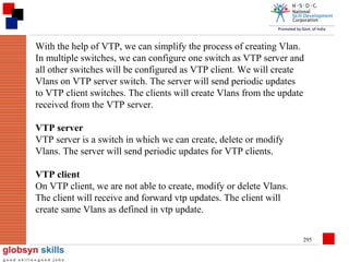
![Commands to create Vlan
Switch#config ter
Switch(config)#vlan <no>
[name <word>]
Switch(config)#exit
optional
Or
Switch#vlan database
Switch(vlan)#vlan <no>
[name <word>]
Switch(vlan)#exit
288](https://image.slidesharecdn.com/networkingpptss2012-131215100852-phpapp01/85/Networking-ppt-287-320.jpg)


![Operation
A message transfer agent receives mail from either another MTA, a mail
submission agent (MSA), or a mail user agent (MUA). The transmission
details are specified by the Simple Mail Transfer Protocol (SMTP). When a
recipient mailbox of a message is not hosted locally, the message is relayed,
that is, forwarded to another MTA. Every time an MTA receives an email
message, it adds aReceived trace header field to the top of the header of the
message,[4] thereby building a sequential record of MTAs handling the
message. The process of choosing a target MTA for the next hop is also
described in SMTP, but can usually be overridden by configuring the MTA
software with specific routes.
463](https://image.slidesharecdn.com/networkingpptss2012-131215100852-phpapp01/85/Networking-ppt-462-320.jpg)


![The syntax to create Extended
ACL
Router#conf ter
Router(config)#access-list <no> <deny|permit> <protocol>
<source> [<s.port>]
<destination> [<d.port>]
router(config)#exit
<no>
->
100 to 199
<protocol> ->
layer ¾
IP
TCP
UDP
ICMP
IGRP
489](https://image.slidesharecdn.com/networkingpptss2012-131215100852-phpapp01/85/Networking-ppt-488-320.jpg)


More Related Content
What's hot (20)
Viewers also liked (19)


Similar to Networking ppt (20)


Recently uploaded (20)


Networking ppt
- 1. SKILLS FOR INDIA Overview of Networking
- 2. Basics of Networking An overview of computer networking which introduces many key concepts and terminology. Sets the stage for future topics. 2
- 3. A network consists of 2 or more computers connected together, and they can communicate and share resources (e.g. information) 3
- 4. Communications – activity associated with distributing or exchanging information Telecommunications – technology of communications at a distance that permits information to be created any where and used everywhere with little delay A network is a way to get “stuff” between 2 or more “things” Examples: Mail, phone system, conversations, railroad system, highways and roads 4
- 5. Must have a message Message must have a transmitter Message must have a medium Message must be understood Message must have some level of security Destination System Source System Source Transmitter Transmission Receiver Destination 1 2 Workstation/PC 3 Medium 4 5 Workstation/PC 5
- 6. Essentials for Network 1. 2. 3. 4. 5. 6. Text input information Input data digital bit stream Transmitted analog signal Received analog signal Output data digital bit stream Text output information 6
- 7. General Architecture of Computer Networks External nodes (or stations) Cloud Internal nodes (swithing devices) 7
- 9. Document Amendment History Document Amendment History S.No Description Author Version Date 1 2 3 4 5 6 7 8 9
- 10. T H A N K Y O U. . . All information, including graphical representations, etc provided in this presentation is for exclusive use of current Globsyn Skills students and faculty. No part of the document may be reproduced in any form or by any means, electronic or otherwise, without written permission of the owner. 10
- 12. Bus Topology Bus: each node is daisy-chained (connected one right after the other) along the same backbone. Information sent from a node travels along the backbone until it reaches its destination node. Each end of a bus network must be terminated with a resistor to keep the 12
- 13. Ring Topology Similar to a bus network, rings have nodes daisy chained, but the end of the network in a ring topology comes back around to the first node, creating a complete circuit. Each node takes a turn sending and receiving information through the use of a token. The token along with any data is sent from the first node to the second node which extracts the data addressed to it and adds any data it wishes to send. Then second node passes the token and data to the third node, etc. until it comes back around to the first node again. Only the node with the token is allowed to send data . All other nodes must wait for the token to come to them. 13
- 14. Star Topology In a star network, each node is connected to a central device called a hub. The hub takes a signal that comes from any node and passes it along to all the other nodes in the network A hub does not perform any type of filtering or routing of the data A hub is a junction that joins all the different nodes together 14
- 15. Star-Bus Topology Prob. Most common topology used today. Combines elements of the star and bus topologies to create a versatile network environment Nodes in particular areas are connected to hubs (and create star topology), and hubs are connected together along the network backbone (like a bus network) Often you have stars nested within stars 15
- 16. Mesh Topology It is also called a point-to-point topology Each device is connected directly to all other network devices It provides fault tolerance It is only found in wide area networks 16
- 17. Other network topologies Some basic network topologies not previously mentioned: One-to-one Hierarchical Hybrid Client-server Multiple nodes 17
- 18. Document Amendment History Document Amendment History S.No Description Author Version Date 1 2 3 4 5 6 7 8 18
- 19. T H A N K Y O U. . . All information, including graphical representations, etc provided in this presentation is for exclusive use of current Globsyn Skills students and faculty. No part of the document may be reproduced in any form or by any means, electronic or otherwise, without written permission of the owner. 19
- 20. SKILLS FOR INDIA Types of Network
- 21. Network configuration Classification based on how computers behave in a network Two classifications are Peer-to-Peer network Server based network 21
- 22. Peer-to-Peer network Nodes provide and request services User in each node administers resources No extra investment Easy to setup Very weak security Additional load on nodes 22
- 23. Server based network Designated computer to administer Resources centralized Supports larger networks Strong security Expensive 23
- 24. Advantages of peer-to-peer networks: Low cost Simple to configure User has full accessibility of the computer Disadvantages of peer-to-peer networks: May have duplication in resources Difficult to uphold security policy Difficult to handle uneven loading Where peer-to-peer network is appropriate: 10 or less users No specialized services required Security is not an issue Only limited growth in the foreseeable future 24
- 25. Clients and Servers Network Clients (Workstation) Workstation Computers that request network resources or services Network Servers Computers that manage and provide network resources and services to clients Usually have more processing power, memory and hard disk space than clients Run Network Operating System that can manage not only data, but also users, groups, security, and applications on the network Servers often have a more stringent requirement on its performance and reliability 25
- 26. Advantages of client/server networks Facilitate resource sharing – centrally administrate and control Facilitate system backup and improve fault tolerance Enhance security – only administrator can have access to Server Support more users – difficult to achieve with peer-to-peer networks Disadvantages of client/server networks High cost for Servers Need expert to configure the network Introduce a single point of failure to the system 26
- 27. Document Amendment History Document Amendment History S.No Description Author Version Date 1 2 3 4 5 6 7 8 27
- 28. T H A N K Y O U. . . All information, including graphical representations, etc provided in this presentation is for exclusive use of current Globsyn Skills students and faculty. No part of the document may be reproduced in any form or by any means, electronic or otherwise, without written permission of the owner. 28
- 29. SKILLS FOR INDIA Networking Media and Components
- 30. Coaxial cable Widely installed for use in business and corporation Ethernet and other types of LANs. Consists of inter copper insulator covered by cladding material, and then covered by an outer jacket Physical Descriptions: Inner conductor is solid copper metal Separated by insulating material Outer conductor is braided shielded (ground) Covered by sheath material 30
- 31. Applications: TV distribution (cable tv); long distance telephone transmission; short run computer system links Local area networks Transmission characteristics: Can transmit analog and digital signals Usable spectrum for analog signaling is about 400 Mhz Amplifier needed for analog signals for less than 1 Km and less distance for higher frequency Repeater needed for digital signals every Km or less distance for higher data rates Operation of 100’s Mb/s over 1 Km 31
- 32. Twisted Pair Cables Physical description: Each wire with copper conductor Separately insulated wires Twisted together to reduce cross talk Often bundled into cables of two or four twisted pairs If enclosed in a sheath then is shielded twisted pair (STP) otherwise often for home usage unshielded twisted pair (UTP). Must be shield from voltage lines Application: Common in building for digital signaling used at speed of 10’s Mb/s (CAT3) and 100Mb/s (CAT5) over 100s meters. Common for telephone interconnection at home and office buildings Less expensive medium; limited in distance, bandwidth, and data rate 32
- 33. Categories of Twisted Pairs Cabling System Category Maximum data rate Usual application CAT 1 Less than 1 Mbps analog voice (plain old telephone service) Integrated Services Digital Network Basic Rate Interface in ISDN Doorbell wiring CAT 2 4 Mbps Mainly used in the IBM Cabling System for token ring networks CAT 3 16 Mbps Voice and data on 10BASE-T Ethernet (certify 16Mhz signal) CAT 4 20 Mbps Used in 16Mbps Token Ring Specs describe cable Material, type of Connectors, and Junction blocks to Conform to a category Otherwise not used much CAT 5 100 Mbps 100 Mbps TPDDI 155 Mbps asynchronous transfer mode (certify 100 Mhz signal) 33
- 34. Optical Fibers Physical Description: Glass or plastic core of optical fiber = 2to125 µm Cladding is an insulating material Jacket is a protective cover Laser or light emitting diode provides transmission light source Applications: Long distance telecommunication Greater capacity; 2 Gb/s over 10’s of Km Smaller size and lighter weight Lower attenuation (reduction in strength of signal) Electromagnetic isolation – not effected by external electromagnetic environment. Aka more privacy Greater repeater spacing – fewer repeaters, reduces line regeneration cost 34
- 35. Multimode fiber is optical fiber that is designed to carry multiple light rays or modes concurrently, each at a slightly different reflection angle within the optical fiber core. used for relatively short distances because the modes tend to disperse over longer lengths (this is called modal dispersion) For longer distances, single mode fiber (sometimes called monomode) fiber is used. In single mode fiber a single ray or mode of light act as a carrier 35
- 36. Wireless Transmission Frequency range (line of sight): 26 GHz to 40 GHz: for microwave with highly directional beam as possible 30 MHz to 1 GHz: for omni directional applications 300MHz to 20000 GHz: for infrared spectrum; used for point to point and multiple point application (line of sight) Physical applications: Terrestrial microwave – long haul telecommunication service (alternative to coaxial or optical fiber) Few amplifier and repeaters Propagation via towers located without blockage from trees, etc (towers less than 60 miles apart) 36
- 37. Satellite is a microwave relay station Geostationary orbit (22,000 miles) and low orbit (12000 miles) Satellite ground stations are aligned to the space satellite, establishes a link, broadcast at a specified frequency. Ground station normally operate at a number of frequencies – full duplex Satellite space antenna is aligned to the ground station establishes a link and transmits at the specified frequency. Satellite are capable of transmitting at multiple frequencies simultaneously, full duplex. To avoid satellites from interfering with each other, a 4 degree separation is required for 4/6 GHz band and 3 degree for 12/14 GHz band. Limited to 90 satellites Disadvantage: not satellite repair capability; greater delay and attenuation problems 37
- 38. Wireless LAN Wireless LAN Hiper LAN (European standard; allow communication at up to 20 Mbps in 5 GHz range of the radio frequency (RF) spectrum Hiper LAN/2 operate at about 54 Mbps in the same RF band 38
- 39. Document Amendment History Document Amendment History S.No Description Author Version Date 1 2 3 4 5 6 7 8 39
- 40. T H A N K Y O U. . . All information, including graphical representations, etc provided in this presentation is for exclusive use of current Globsyn Skills students and faculty. No part of the document may be reproduced in any form or by any means, electronic or otherwise, without written permission of the owner. 40
- 41. SKILLS FOR INDIA Network Components
- 42. Hubs A hub is the place where data converges from one or more directions and is forwarded out in one or more directions. Seen in local area networks 42
- 43. Gateways A gateway is a network point that acts as an entrance to another network. On the internet, in terms of routing, the network consists of gateway nodes and host nodes Host nodes are computer of network users and the computers that serve contents (such as Web pages) Gateway nodes are computers that control traffic within your company’s network or at your local internet service provider (ISP) 43
- 44. Routers A router is a device or a software in a computer that determines the next network point to which a packet should be forwarded toward its destination Allow different networks to communicate with each other A router creates and maintain a table of the available routes and their conditions and uses this information along with distance and cost algorithms to determine the best route for a given packet A packet will travel through a number of network points with routers before arriving at its destination 44
- 45. Bridge A bridge is a product that connects a local area network (LAN) to another local area network that uses the same protocol (for example, Ethernet or token ring) A bridge examines each message on a LAN, "passing" those known to be within the same LAN, and forwarding those known to be on the other interconnected LAN (or LANs) 45
- 46. Differences Bridge: device to interconnect two LANs that use the SAME logical link control protocol but may use different medium access control protocols Router: device to interconnect SIMILAR networks, e.g. similar protocols and workstations and servers Gateway: device to interconnect DISSIMILAR protocols and servers, and Macintosh and IBM LANs and equipment 46
- 47. Switches Allow different nodes of a network to communicate directly with each other Allow several users to send information over a network at the same time without slowing each other down 47
- 48. Document Amendment History Document Amendment History S.No Description Author Version Date 1 2 3 4 5 6 7 8 48
- 49. T H A N K Y O U. . . All information, including graphical representations, etc provided in this presentation is for exclusive use of current Globsyn Skills students and faculty. No part of the document may be reproduced in any form or by any means, electronic or otherwise, without written permission of the owner. 49
- 50. SKILLS FOR INDIA IEEE Standards
- 51. Introduction IEEE 802 refers to a family of IEEE standards Dealing with local area network and metropolitan area network Restricted to networks carrying variable-size packets Specified in IEEE 802 map to the lower two layers • Data link layer – LLC sub layer – MAC sub layer • Physical layer The most widely used standards The Ethernet family, Token Ring, Wireless LAN Bridging and Virtual Bridged LANs An individual Working Group provides the focus for each area 51
- 52. IEEE 802 Working Groups Active working groups 802.1 Inactive or disbanded working groups 802.2 Logical Link Control Working Group Group 802.3 Higher Layer LAN Protocols Working 802.4 Token Bus Working Group Ethernet Working Group 802.5 Token Ring Working Group 802.7 Broadband Area Network Working 802.11 Wireless LAN Working Group 802.15 Wireless Personal Area Network (WPAN) Working Group 802.16 Broadband Wireless Access Working Group Group 802.8 Fiber Optic TAG 802.9 Integrated Service LAN Working Group 802.17 Resilient Packet Ring Working Group 802.10 Security Working Group 802.18 Radio Regulatory TAG 802.12 Demand Priority Working Group 802.19 Coexistence TAG 802.14 Cable Modem Working Group 802.20 Mobile Broadband Wireless Access (MBWA) Working Group 802.21 Media Independent Handoff Working Group 52
- 53. 802.11 Wireless LAN Working Group Types Infrastructure based Ad-hoc AP Advantages Flexible deployment Minimal wiring difficulties More robust against disasters (earthquake etc) AP wired network Disadvantages Low bandwidth compared to wired networks (1-10 Mbit/s) Need to follow wireless spectrum regulations Not support mobility AP: Access Point AP 53
- 54. 802.11 Wireless LAN Working Group 802.11 802.11 802.11a 802.11b Protocol Release date Op. Frequency Legacy 1997 2.5~2.5 GHz 802.11a 1999 802.11b 802.11g 802.11n Data rate (Max) 2 Mbit/s Range (indoor) Range (outdoor) 5.15~5.35/5.47~5.725 /5.725~5.875 GHz 54 Mbit/s ~25 m ~75 m 1999 2.4~2.5GHz 11 Mbit/s ~35 m ~100 m 802.11g 2003 2.4~2.5GHz 54 Mbit/s ~25 m ~75 m 802.11n 2007 2.4GHz or 5GHz 540 Mbit/s ~50 m ~125 m 54
- 55. 802.11n Working Group What is the 802.11n? Uses MIMO radio technology and OFDM as a basis Anywhere from 100Mbps to 600Mbps depending on implementation Support both 2.4 GHz and 5 GHz Use multiple stream 802.11n increase transmission efficiency of MAC Cutting guard band time in half Reducing the number of pilot carrier, for data Aggregating frames and bursting Using a 40MHz instead of a 20MHz channel 30~50% => 70% 55
- 56. 802.11n Working Group Timeline Draft 1.0 failed IEEE meeting ballot IEEE record – 12,000 comments received Draft 2.0 is now required – Orlando March 2007 IEEE Meeting Pre-N certification program start March 2007 Result – expect ratification in early 2008 56
- 57. 802.15 Wireless Personal Area Network(WPAN) Working Groups summary 802.15 802.15.1 802.15.2 802.15.3 802.15.1 : WPAN/Bluetooth 802.15.2 : Coexistence Group 802.15.3a 802.15.3 : High Rate(HR) WPAN Group 802.15.3a : WPAN HR Alternative PHY Task Group 802.15.3b : MAC Amendment Task Group 802.15.4 : Low Rate(LW) WPAN Group(Zigbee) 802.15.4a : WPAN Low Rate Alternative PHY 802.15.4b : Revisions and Enhancements UWB Forum 802.15.3b 802.15.4 802.15.4a 802.15.4b 57
- 58. 802.16 Broadband Wireless Access(BWA) IEEE 802.16 Be was established by IEEE Standards Board in 1999, aims to prepare formal specifications for the global deployment of broadband Wireless Metropolitan Area Network. A unit of the IEEE 802 LAN/MAN Standards Committee. A related technology Mobile Broadband Wireless Access(MBWA) Mobile (Vehicular) WWAN (IMT-2000) cdma2000® 1xEV-DO, cdma2000® 1xEV-DV 2G/2.5G 802.16e Pedestrian (Nomadic) Cellular WCDMA HSDPA 802.15.1 (Bluetooth) 0.1 802.16a (WiMAX) 802.15.3a (UWB) 802.11 (WLAN) 1.0 3.1 10 100 58
- 59. 802.16 Broadband Wireless Access (BWA) 802.16 802.16.f 802.15.g 802.15.h 802.15.i 802.15.j 802.15.m 802.15.k 802.16f : Management Information Base 802.16g : Management Plane Procedures and Services 802.16h : Improved Coexistence Mechanisms for License-Exempt Operation 802.16i : Mobile Management Information Base 802.16j : Multihop Relay Specification 802.16k : Bridging of 802.16 802.16m : Advanced Air Interface. 59
- 60. Document Amendment History Document Amendment History S.No Description Author Version Date 1 2 3 4 5 6 7 8 60
- 61. T H A N K Y O U. . . All information, including graphical representations, etc provided in this presentation is for exclusive use of current Globsyn Skills students and faculty. No part of the document may be reproduced in any form or by any means, electronic or otherwise, without written permission of the owner. 61
- 62. SKILLS FOR INDIA Types of Network
- 63. Major Categories of Networks Local Area Network Metropolitan Area network Wide area network The internet Personal Area Network 63
- 64. Local Area Network A Local Area Network (LAN) is a relatively small network that is confined to a small geographic area, such as a single office or a building. Laptops, desktops, servers, printers, and other networked devices that make up a LAN are located relatively close to each other. A key characteristic is that all of the equipment that comprises a LAN, is owned by a single entity. 64
- 65. Metropolitan Area Network The term Metropolitan Area Network (MAN) is typically used to describe a network that spans a citywide area or a town. MANs are larger than traditional LANs and predominantly use high-speed media, such as fiber optic cable, for their backbones. MANs are common in organizations that need to connect several smaller facilities together for information sharing. This is often the case for hospitals that need to connect treatment facilities, outpatient facilities, doctor's offices, labs, and research offices for access to centralized patient and treatment information. MANs share many of the same security threats as LANs, but on a larger scale. The plight of an administrator in a central location granting access to countless offices that are scattered within a city is a difficult one that demands strict access control mechanisms to protect against unauthorized information access. 65
- 67. Wide Area Network A Wide Area Network (WAN) covers a significantly larger geographic area than LANs or MANs. A WAN uses public networks, telephone lines, and leased lines to tie together smaller networks such as LANs and MANs over a geographically dispersed area. Connecting devices in different geographic areas together for information sharing, WANs are an important piece of enterprise networks. For example, consider the VisaNet global network used by Visa International. The VisaNet network connects locations throughout 150 countries to validate and debit credit-card transactions at over 24 million locations. By providing security and simplicity over a standardbased WAN architecture, Visa International relies on their network infrastructure to provide reliable access to merchants who accept Visa credit cards for transactions. 67
- 69. Personal Area Network A more recent term used to describe a type of network is a Personal Area Network (PAN). PAN networks are usually wireless, established in an ondemand or ad-hoc fashion when needed to communicate between two or more devices. PAN networks can be used between devices owned by two different parties, or between two devices owned by one person, such as a PDA and a laptop or mobile phone. These networks are usually characterized as short-range, often limited to 10 meters or less in range. An example of a PAN technology is Bluetooth wireless networking. Bluetooth is designed as a cable-replacement technology, allowing users to discard the serial and USB cables used by many of today's peripheral devices and rely on a Bluetooth PAN for communication. Bluetooth PANs support up to 7 devices in a single network and can be used for proprietary protocols (such as PDA synchronization) or standards-based protocols, including Internet access over IP and the Bluetooth Network Encapsulation Protocol 69 (BNEP).
- 71. Data Communications Through WANs WANs were developed to communicate over a large geographical area (e.g. lab-to-lab; city-to-city; east coast-to-west coast; North America-toSouth America etc) WANs require the crossing of public right of ways (under control and regulations of the interstate commerce and institute of telephone and data communications established by the gov’t and international treaties). WANs around the world relies on the infrastructure established by the telephone companies (“common carrier”) or public switched telephone network (PSTN) WANs consists of a number of interconnected switching nodes (today = computers). Transmission signals are routed across the network automatically by software control to the specified destination. The purpose of these nodes are to route messages through switching facilities to move data from node to node to its destination 71
- 72. WANs originally implemented circuit switching and packet switching technologies. Recently, frame relay and asynchronous transfer mode (ATM) networks have been implemented to achieve higher operating and processing speeds for the message WAN are owned by the common carrier in the U.S. and government in most foreign countries Interconnected devices, I.e. LANs or Personal Computers (PC) or Workstation or Servers can be (usually are) privately owned by companies 72
- 73. Document Amendment History Document Amendment History S.No Description Author Version Date 1 2 3 4 5 6 7 8 73
- 74. T H A N K Y O U. . . All information, including graphical representations, etc provided in this presentation is for exclusive use of current Globsyn Skills students and faculty. No part of the document may be reproduced in any form or by any means, electronic or otherwise, without written permission of the owner. 74
- 75. SKILLS FOR INDIA OSI Model
- 76. ISO/OSI Reference Model Open Systems Interconnection No one really uses this in the real world. A reference model so others can develop detailed interfaces Value: The reference model defines 7 layers of functions that take place at each end of communication and with each layer adding its own set of special related functions Flow of data through each layer at one 76
- 77. ISO/OSI Reference Model File Transfer, Email, Remote Login ASCII Text, Sound (syntax layer) Establish/manage connection End-to-end control & error checking (ensure complete data transfer): TCP Routing and Forwarding Address: IP Two party communication: Ethernet How to transmit signal; coding Hardware means of sending an receiving data on a carrier 77
- 78. Layer 1: Physical layer The physical layer defines electrical and physical specifications for devices. In particular, it defines the relationship between a device and a transmission medium, such as a copper or fiber optical cable. The major functions and services performed by the physical layer are: Establishment and termination of a connection to a communications medium Participation in the process whereby the communication resources are effectively shared among multiple users. For example, contention resolution and flow control 78
- 79. Modulation, or conversion between the representation of digital data in user equipment and the corresponding signals transmitted over a communications channel. These are signals operating over the physical cabling (such as copper and optical fiber) or over aradio link Parallel SCSI buses operate in this layer, although it must be remembered that the logical SCSI protocol is a transport layer protocol that runs over this bus. Various physical-layer Ethernet standards are also in this layer; Ethernet incorporates both this layer and the data link layer. The same applies to other local-area networks, such as token ring, FDDI, ITUT G.hn and IEEE 802.11, as well as personal area networks such as Bluetooth and IEEE 802.15.4. 79
- 80. Layer 2: Data link layer The data link layer provides the functional and procedural means to transfer data between network entities and to detect and possibly correct errors that may occur in the physical layer. Originally, this layer was intended for point-to-point and point-to-multipoint media, characteristic of wide area media in the telephone system. Local area network architecture, which included broadcast-capable multi access media, was developed independently of the ISO work in IEEE Project 802. IEEE work assumed sub-layering and management functions not required for WAN use. In modern practice, only error detection, not flow control using sliding window, is present in data link protocols such as Point-to-Point Protocol (PPP), and, on local area networks, the IEEE 802.2 LLC layer is not used for most protocols on the Ethernet, and on other local area networks, its flow control and acknowledgment mechanisms are rarely used. Sliding window flow control and acknowledgment is used at the transport layer by protocols such as TCP, but is still used in niches where X.25 offers performance advantages. 80
- 81. The ITU-T G.hn standard, which provides high-speed local area networking over existing wires (power lines, phone lines and coaxial cables), includes a complete data link layer which provides both error correction and flow control by means of a selective repeat Sliding Window Protocol. Both WAN and LAN service arrange bits, from the physical layer, into logical sequences called frames. Not all physical layer bits necessarily go into frames, as some of these bits are purely intended for physical layer functions. For example, every fifth bit of the FDDI bit stream is not used by the layer. 81
- 82. Layer 3: Network layer The network layer provides the functional and procedural means of transferring variable length data sequences from a source host on one network to a destination host on a different network (in contrast to the data link layer which connects hosts within the same network), while maintaining the quality of service requested by the transport layer. The network layer performs network routing functions, and might also perform fragmentation and reassembly, and report delivery errors. Routers operate at this layer, sending data throughout the extended network and making the Internet possible. This is a logical addressing scheme – values are chosen by the network engineer. The addressing scheme is not hierarchical. 82
- 83. Layer 3: Network layer The network layer may be divided into three sub layers: Sub network access – that considers protocols that deal with the interface to networks, such as X.25; Sub network-dependent convergence – when it is necessary to bring the level of a transit network up to the level of networks on either side Sub network-independent convergence – handles transfer across multiple networks 83
- 84. An example of this latter case is CLNP, or IPv6 ISO 8473. It manages the connectionless transfer of data one hop at a time, from end system to ingress router, router to router, and from egress router to destination end system. It is not responsible for reliable delivery to a next hop, but only for the detection of erroneous packets so they may be discarded. In this scheme, IPv4 and IPv6 would have to be classed with X.25 as subnet access protocols because they carry interface addresses rather than node addresses. A number of layer-management protocols, a function defined in the Management Annex, ISO 7498/4, belong to the network layer. These include routing protocols, multicast group management, network-layer information and error, and network-layer address assignment. It is the function of the payload that makes these belong to the network layer, not the protocol that carries 84
- 85. Layer 4: Transport layer The transport layer provides transparent transfer of data between end users, providing reliable data transfer services to the upper layers. The transport layer controls the reliability of a given link through flow control, segmentation/desegmentation, and error control. Some protocols are stateand connection-oriented. This means that the transport layer can keep track of the segments and retransmit those that fail. The transport layer also provides the acknowledgement of the successful data transmission and sends the next data if no errors occurred. 85
- 86. OSI defines five classes of connection-mode transport protocols ranging from class 0 (which is also known as TP0 and provides the least features) to class 4 (TP4, designed for less reliable networks, similar to the Internet). Class 0 contains no error recovery, and was designed for use on network layers that provide error-free connections. Class 4 is closest to TCP, although TCP contains functions, such as the graceful close, which OSI assigns to the session layer. Also, all OSI TP connection-mode protocol classes provide expedited data and preservation of record boundaries. Although not developed under the OSI Reference Model and not strictly conforming to the OSI definition of the transport layer, the Transmission Control Protocol (TCP) and the User Datagram Protocol (UDP) of the Internet Protocol Suite are commonly categorized as layer-4 protocols within OSI. 86
- 87. Layer 5: Session layer The session layer controls the dialogues (connections) between computers. It establishes, manages and terminates the connections between the local and remote application. It provides for full-duplex, half-duplex, or simplex operation, and establishes checkpointing, adjournment, termination, and restart procedures. The OSI model made this layer responsible for graceful close of sessions, which is a property of the Transmission Control Protocol, and also for session check pointing and recovery, which is not usually used in the Internet Protocol Suite. The session layer is commonly implemented explicitly in application environments that use remote procedure calls. On this level, InterProcess_(computing) communication happen (SIGHUP, SIGKILL, End Process, etc.). 87
- 88. Layer 6: Presentation layer The presentation layer establishes context between application-layer entities, in which the higher-layer entities may use different syntax and semantics if the presentation service provides a mapping between them. If a mapping is available, presentation service data units are encapsulated into session protocol data units, and passed down the stack. This layer provides independence from data representation (e.g., encryption) by translating between application and network formats. The presentation layer transforms data into the form that the application accepts. This layer formats and encrypts data to be sent across a network. It is sometimes called the syntax layer. The original presentation structure used the basic encoding rules of Abstract Syntax Notation One (ASN.1), with capabilities such as converting an EBCDIC-coded text file to an ASCII-coded file, or serialization of objects and other data structures from and to XML. 88
- 89. Layer 7: Application layer The application layer is the OSI layer closest to the end user, which means that both the OSI application layer and the user interact directly with the software application. This layer interacts with software applications that implement a communicating component. Such application programs fall outside the scope of the OSI model. Application-layer functions typically include identifying communication partners, determining resource availability, and synchronizing communication. When identifying communication partners, the application layer determines the identity and availability of communication partners for an application with data to transmit. When determining resource availability, the application layer must decide whether sufficient network or the requested communication exist. In synchronizing communication, all communication between applications requires cooperation that is managed by the application layer. 89
- 90. Comparison with TCP/IP Model In the TCP/IP model of the Internet, protocols are deliberately not as rigidly designed into strict layers as in the OSI model. [10] RFC 3439 contains a section entitled "Layering considered harmful (section link here )." However, TCP/IP does recognize four broad layers of functionality which are derived from the operating scope of their contained protocols, namely the scope of the software application, the end-to-end transport connection, the internetworking range, and the scope of the direct links to other nodes on the local network. Even though the concept is different from the OSI model, these layers are nevertheless often compared with the OSI layering scheme in the following way: The Internet application layer includes the OSI application layer, presentation layer, and most of the session layer. Its end-to-end transport layer includes the graceful close function of the OSI session layer as well as the OSI transport layer. 90
- 91. The internetworking layer (Internet layer) is a subset of the OSI network layer (see above), while the link layer includes the OSI data link and physical layers, as well as parts of OSI's network layer. These comparisons are based on the original seven-layer protocol model as defined in ISO 7498, rather than refinements in such things as the internal organization of the network layer document. The presumably strict peer layering of the OSI model as it is usually described does not present contradictions in TCP/IP, as it is permissible that protocol usage does not follow the hierarchy implied in a layered model. Such examples exist in some routing protocols (e.g., OSPF), or in the description of tunneling protocols, which provide a link layer for an application, although the tunnel host protocol may well be a transport or even an application layer protocol in its own right. 91
- 92. Document Amendment History Document Amendment History S.No Description Author Version Date 1 2 3 4 5 6 7 8 92
- 93. T H A N K Y O U. . . All information, including graphical representations, etc provided in this presentation is for exclusive use of current Globsyn Skills students and faculty. No part of the document may be reproduced in any form or by any means, electronic or otherwise, without written permission of the owner. 93
- 94. SKILLS FOR INDIA Understanding Network Protocols
- 95. Protocols of Computer Communications and Networks Protocol are used for communication between computers in different computer networks. Protocol achieves: What is communicated between computers? How it is communicated? When it is communicated? What conformance (bit sequence) between computers? Key elements of a protocol are: SYNTAC: Data format and signal levels SEMANTICS: Control information for coordination and error handling TIMING: Synchronization, speed matching, and sequencing Examples of protocols: WAN Protocol: TCP/IP 95
- 96. The Internet Protocol Suite and the OSI Reference Model 96
- 97. TCP The Transmission Control Protocol (TCP) is one of the core protocols of the Internet Protocol Suite. TCP is one of the two original components of the suite, complementing the Internet Protocol (IP), and therefore the entire suite is commonly referred to as TCP/IP. TCP provides reliable, ordered delivery of a stream of bytes from a program on one computer to another program on another computer. TCP is the protocol used by major Internet applications such as the World Wide Web, email, remote administration and file transfer. Other applications, which do not require reliable data stream service, may use the User Datagram Protocol (UDP), which provides datagram service that emphasizes reduced latency over reliability. 97
- 98. User Datagram Protocol The User Datagram Protocol (UDP) is one of the core members of the Internet Protocol Suite, the set of network protocols used for the Internet. With UDP, computer applications can send messages, in this case referred to as datagram, to other hosts on an Internet Protocol (IP) network without requiring prior communications to set up special transmission channels or data paths. The protocol was designed by David P. Reed in 1980 and formally defined in RFC 768 . UDP uses a simple transmission model without implicit handshaking dialogues for providing reliability, ordering, or data integrity. Thus, UDP provides an unreliable service and datagram may arrive out of order, appear duplicated, or go missing without notice. UDP assumes that error checking and correction is either not necessary or performed in the application, avoiding the overhead of such processing at the network interface level. Time-sensitive applications often use UDP because dropping packets is preferable to waiting for delayed packets, which may not be an option in a real-time system. 98
- 99. Internet Control Message Protocol The Internet Control Message Protocol (ICMP) is one of the core protocols of the Internet Protocol Suite. It is chiefly used by the operating systems of networked computers to send error messages indicating, for example, that a requested service is not available or that a host or router could not be reached. ICMP can also be used to relay query messages. It is assigned protocol number 1. ICMP differs from transport protocols such as TCP and UDP in that it is not typically used to exchange data between systems, nor is it regularly employed by end-user network applications (with the exception of some diagnostic tools like ping and trace route). ICMP for Internet Protocol version 4 (IPv4) is also known as ICMPv4. IPv6 has a similar protocol, ICMPv6. 99
- 100. Hypertext Transfer Protocol Hypertext Transfer Protocol (HTTP) is an application protocol for distributed, collaborative, hypermedia information systems. HTTP is the foundation of data communication for the World Wide Web. Hypertext is a multi-linear set of objects, building a network by using logical links (the so-called hyperlinks) between the nodes (e.g. text or words). HTTP is the protocol to exchange or transfer hypertext. The standards development of HTTP was coordinated by the Internet Engineering Task Force (IETF) and the World Wide Web Consortium (W3C), culminating in the publication of a series of Requests for Comments (RFCs), most notably RFC 2616 (June 1999), which defines HTTP/1.1, the version of HTTP in common use. 100
- 101. Post Office Protocol In computing, the Post Office Protocol (POP) is an applicationlayer Internet standard protocol used by locale-mail clients to retrieve email from a remote server over a TCP/IP connection. POP and IMAP (Internet Message Access Protocol) are the two most prevalent Internet standard protocols for e-mail retrieval. Virtually all modern e-mail clients and servers support both. The POP protocol has been developed through several versions, with version 3 (POP3) being the current standard. Most webmail service providers such as Hotmail, Gmail and Yahoo! Mail also provide IMAP and POP3 service. 101
- 102. File Protocol Transfer File Transfer Protocol (FTP) is a standard network protocol used to transfer files from one host to another host over a TCP-based network, such as the Internet. It is often used to upload web pages and other documents from a private development machine to a public web-hosting server. FTP is built on a client-server architecture and uses separate control and data connections between the client and the server. FTP users may authenticate themselves using a clear-text sign-in protocol, normally in the form of a username and password, but can connect anonymously if the server is configured to allow it. For secure transmission that hides (encrypts) the username and password, and encrypts the content, SSH File Transfer Protocol may be used. 102
- 103. Internet Message Control Protocol Internet message access protocol (IMAP) is one of the two most prevalent Internet standard protocols for email retrieval, the other being the Post Office Protocol (POP). Virtually all modern e-mail clients and mail servers support both protocols as a means of transferring e-mail messages from a server. The Internet Message Access Protocol (commonly known as IMAP) is an Application Layer Internet protocol that allows a client to access email on a remote mail server. The current version, IMAP version 4 revision 1 (IMAP4rev1), is defined by RFC 3501. An IMAP server typically listens on well-known port 143. IMAP over SSL (IMAPS) is assigned well-known port number 993. 103
- 104. IPX/SP X IPX/SPX is a routable protocol and can be used for small and large networks. It was created by Novell primarily for Novell NetWare networks, but is popular enough that it is used on products that are not from Novell. •NCP - NetWare Core Protocol provides for client/server interactions such as file and print sharing. It works at the application, presentation, and session levels. •SAP - Service Advertising Protocol packets are used by file and print servers to periodically advertise the address of the server and the services available. It works at the application, presentation, and session levels. 104
- 105. IPX/SP X •SPX - Sequenced Packet Exchange operates at the transport layer providing connection oriented communication on top of IPX. •IPX - Internetwork Packet Exchange supports the transport and network layers of the OSI network model. Provides for network addressing and routing. It provides fast, unreliable, communication with network nodes using a connection less datagram service. 105
- 106. Other Network Support ODI - Open Data-link Interface operates at the data link layer allowing IPX to work with any network interface card RIP - Routing Information Protocol is the default routing protocol for IPX/SPX networks which operates at the network layer. A distance-vector algorithm is used to calculate the best route for a packet MHS - Message Handling Service by Novell is used for mail on Netware networks Network Level Protocols Application Presentation NCP SAP Session Transport Network Data Link IPX SPX NDIS/NIC drivers 106
- 107. NetBIOS NetBIOS is an acronym for Network Basic Input/Output System. It provides services related to the session layer of the OSI model allowing applications on separate computers to communicate over a local area network. As strictly an API, NetBIOS is not a networking protocol. Older operating systems ran NetBIOS over IEEE 802.2 and IPX/SPX using the NetBIOS Frames (NBF) and NetBIOS (NBX) protocols, respectively. In modern networks, NetBIOS normally runs over TCP/IP via the NetBIOS over TCP/IP (NBT) protocol. This results in each computer in the network having both an IP address and a NetBIOS name corresponding to a (possibly different) host name. 107
- 108. NetBEUI (NetBIOS Extended User Interface NetBEUI (NetBIOS Extended User Interface) is a new, extended version of NetBIOS, the program that lets computers communicate within a local area network. NetBEUI formalizes the frame format (or arrangement of information in a data transmission) that was not specified as part of NetBIOS. NetBEUI was developed by IBM for its LAN Manager product and has been adopted by Microsoft for its Windows NT, LAN Manager, and Windows for Workgroups products. Hewlett-Packard and DEC use it in comparable products. NetBEUI is the best performance choice for communication within a single LAN. Because, like NetBIOS, it does not support the routing of messages to other networks, its interface must be adapted to other protocols such as Internetwork Packet Exchange or TCP/IP. A recommended method is to install both NetBEUI and TCP/IP in each computer and set the server up to use NetBEUI for communication within the LAN and TCP/IP for communication beyond the LAN. 108
- 109. Difference between NetBIOS & NetBEUI NetBIOS (Network Basic Input/Output System) isn't a network protocol. It's an API (applications programming interface) for File and Printer Sharing. NetBIOS names identify computers on the network. NetBIOS broadcasts locate computers and shared disks and folders on the network and allow them to appear in My Network Places and Network Neighborhood. NetBEUI (NetBIOS Extended User Interface) is a network protocol, like TCP/IP and IPX/SPX. All three protocols support file and printer sharing using the NetBIOS API. Nothing in Windows networking requires the NetBEUI protocol. All network functions are available using the TCP/IP and/or NW Link IPX/SPX protocols. NetBEUI is available as an un-supported protocol in Windows XP. 109
- 110. Apple Talk AppleTalk is a proprietary suite of networking protocols developed by Apple Inc. for their Mac computers. AppleTalk included a number of features that allowed local area networks to be connected with no prior setup or the need for a centralized router or server of any sort. Simply connecting together AppleTalk equipped systems would automatically assign addresses, update the distributed namespace, and configure any required inter-networking routing. It was a true plug-n-play system. AppleTalk was released for the original Macintosh in 1985, and was the primary protocol used by Apple machinery through the 1980s and 90s. Versions were also released for the IBM PC and compatibles, and the Apple IIGS. AppleTalk support was also available in most networked printers (especially laser printers), some file servers and a number of routers. Through this period, AppleTalk was, by far, the most popular networking system in the world. 110
- 111. Apple Talk..Continued The rise of TCP/IP during the 1990s led to a re-implementation of most of these types of support on that protocol, and AppleTalk became unsupported as of the release of Mac OS X v10.6 in 2009. Many of AppleTalk's more advanced auto-configuration features have since been introduced in Bonjour. 111
- 112. Associated TCP/IP Protocols & Services HTTP This protocol, the core of the World Wide Web, facilitates retrieval and transfer of hypertext (mixed media) documents. Stands for the HyperText Transfer protocol Telnet A remote terminal emulation protocol that enables clients to log on to remote hosts on the network. SNMP Used to remotely manage network devices. Stands for the Simple Network Management Protocol. DNS Provides meaningful names like achilles.mycorp.com for computers to replace numerical addresses like 123.45.67.89. Stands for the Domain Name System. SLIP/ PPP SLIP (Serial Line Internet Protocol) and PPP (Point to Point Protocol) encapsulate the IP packets so that they can be sent over a dial up phone connection to an access provider’s modem. 112
- 113. Document Amendment History Document Amendment History S.No Description Author Version Date 1 2 3 4 5 6 7 8 113
- 114. T H A N K Y O U. . . All information, including graphical representations, etc provided in this presentation is for exclusive use of current Globsyn Skills students and faculty. No part of the document may be reproduced in any form or by any means, electronic or otherwise, without written permission of the owner. 114
- 115. SKILLS FOR INDIA IP Addressing
- 116. What is an IP address? IP (Internet Protocol) address Device used by routers, to select best path from source to destination, across networks and internetworks Network layer address, consisting of NETWORK portion, and HOST portion Logical address, assigned in software by network administrator Part of a hierarchical ‘numbering scheme’ - unique, for reliable routing May be assigned to a host pc, or router port 116
- 117. Types of IP address Static address Dynamic address 117
- 118. Static IP address Manually input by network administrator Manageable for small networks Requires careful checks to avoid duplication 118
- 119. Dynamic IP address Examples - BOOTP, DHCP Assigned by server when host boots Derived automatically from a range of addresses Duration of ‘lease’ negotiated, then address released back to server 119
- 120. Class A IP address 1st octet = network address, octets 2-4 = host address 1st bits of 1st octet set to 0 up to (2^24 - 2) host addresses (16.8M) 121
- 121. Class A IP address 124. 224. 224.100 01111100 11100000 11100000 01100100 122
- 122. Class B IP address 1st 2 octets = network address, octets 3-4 = host address 1st 2 bits of 1st octet set to 10 up to (2^16 - 2) host addresses (65534) 123
- 123. Class B IP address 129. 224. 224. 100 10000001 11100000 11100000 01100100 124
- 124. Class C IP address 1st 3 octets = network address, octet 4 = host address 1st 3 bits of 1st octet set to 110 up to (2^8 - 2) host addresses (254) 125
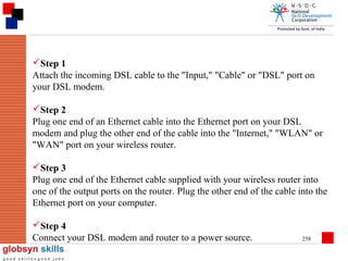
- 125. Class C IP address 193. 224. 224. 100 11000001 11100000 11100000 01100100 126
- 126. IP addresses and routing Routing tables Identifying source and destination IP packet routing 127
- 127. IP addresses and routing -Routing Tables Created by router, held in memory, constantly updated Based on cross-referencing IP packet source address, and port on which received 128
- 128. IP addresses and routing Identifying source and destination As part of a layer 3 packet, IP header contains source and destination address Each address is 32 bits long, and unique to device or port Router reads destination IP address, checks against routing tables 129
- 129. IP addresses and routing - IP packet routing If destination address not on the same segment as receive port, router sends packet to correct port for routing to destination If destination on same segment as receive port, packet not forwarded 130
- 130. Networks and subnets Why subnet Subnet mask Restrictions on ‘borrowed’ bits 131
- 131. When an organization is granted a block of addresses, it can create subnets to meet its needs. The prefix length increases to define the subnet prefix length. Why subnet Reduce broadcast domain, improve network efficiency Why subnet Reduce broadcast domain, improve network efficiency 132
- 132. Subnet masks Extend NETWORK portion, borrow from HOST portion Allow external networks to route packets direct to subnet 133
- 133. SKILLS FOR INDIA IP Routing
- 134. Network Address Translation Network Address Translation or NAT Kinds of Network Address Translation Operation of Network Address Translation Security and Administration 135
- 135. IP Routing When we want to connect two or more networks using different n/w addresses then we have to use IP Routing technique. The router will be used to perform routing between the networks. A router will perform following functions for routing. Path determination Packet forwarding Path determination The process of obtaining path in routing table is called path determination. There are three different methods to which router can learn path. Automatic detection of directly connected n/w. Static & Default routing Dynamic routing 136
- 136. IP Routing Packet forwarding It is a process that is by default enable in router. The router will perform packet forwarding only if route is available in the routing table. 137
- 137. Routing Process The pc has a packet in which destination address is not same as the local n/w address. The pc will send an ARP request for default gateway. The router will reply to the ARP address and inform its Mac address to pc. The pc will encapsulate data, in which source IP is pc itself, destination IP is server, source Mac is pc’s LAN interface and destination Mac is router’s LAN interface. 138
- 138. Routing Process R1 10.0.0.1 S. MAC PC1 D. IP S. IP D. MAC R1 172.16.0.5 10.0.0.6 172.16.0.5 139
- 139. The router will receive the frame, store it into the buffer. When obtain packet from the frame then forward data according to the destination IP of packet. The router will obtain a route from routing table according to which next hop IP and interface is selected According to the next hop, the packet will encapsulated with new frame and data is send to the output queue of the interface. 140
- 140. Static Routing In this routing, we have to use IP route commands through which we can specify routes for different networks. The administrator will analyze whole internetwork topology and then specify the route for each n/w that is not directly connected to the router. Steps to perform static routing Create a list of all n/w present in internetwork. Remove the n/w address from list, which is directly connected to n/w. Specify each route for each routing n/w by using IP route command. Router(config)#ip route <destination n/w> <mask> <next hop ip> Next hop IP it is the IP address of neighbor router that is directly connected our router. 141
- 141. Advantages of static routing (1) Fast and efficient. (2) More control over selected path. (3) Less overhead for router. (4) Bandwidth of interfaces is not consumed in routing updates. Disadvantages of static routing (1) More overheads on administrator. (2) Load balancing is not easily possible. (3) In case of topology change routing table has to be change manually. 142
- 142. Alternate command to specify static route Static route can also specify in following syntax: Old Router(config)#ip route 172.16.0.0 255.255.0.0 172.25.0.2 Or Router(config)#ip route 172.16.0.0 255.255.0.0 serial 0 143
- 143. Backup route or loading static route If more than one path are available from our router to destination then we can specify one route as primary and other route as backup route. Administrator Distance is used to specify one route as primary and other route as backup. Router will select lower AD route to forward the traffic. By default static route has AD value of 1. With backup path, we will specify higher AD so that this route will be used if primary route is unavailable. Protocols AD Directly Connected 0 Static 1 BGP 20 EIGRP 90 IGRP 100 OSPF 110 RIP 120 144
- 144. Syntax: To set backup path Router(config)#ip route <dest. n/w> <mask> <next hop> <AD> Default Routing Default routing means a route for any n/w. these routes are specify with the help of following syntax: Router(config)#ip route 0.0.0.0 0.0.0.0 <next hop> Or <exit interface> To display routing table Router#sh ip route 145
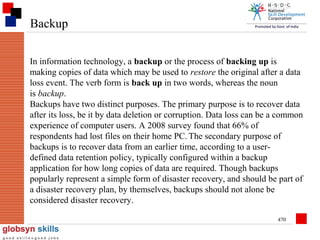
- 145. To display routing table Router#sh ip route To display static routes only Router#sh ip route static S 192.168.10.0/28 [1/0] via 172.16.0.5 To display connected n/ws only Router#sh ip route connected To check all the interface of a router Router#sh interface brief 146
- 146. Dynamic Routing In dynamic routing, we will enable a routing protocol on router. This protocol will send its routing information to the neighbor router. The neighbors will analyze the information and write new routes to the routing table. The routers will pass routing information receive from one router to other router also. If there are more than one path available then routes are compared and best path is selected. Some examples of dynamic protocol are: RIP, IGRP, EIGRP, OSPF Types of Dynamic Routing Protocols According to the working there are two types of Dynamic Routing Protocols. (1) Distance Vector (2) Link State 147
- 147. Dynamic Routing According to the type of area in which protocol is used there are again two types of protocol: (1) Interior Routing Protocol (2) Exterior Routing Protocol Interior Routing Exterior Routing RIP BGP IGRP EXEIGRP EIGRP OSPF 148
- 148. Distance Vector Routing The Routing, which is based on two parameters, that is distance and direction is called Distance Vector Routing. The example of Distance Vector Routing is RIP & IGRP. Operation: (1) Each Router will send its directly connected information to the neighbor router. This information is send periodically to the neighbors. (2) The neighbor will receive routing updates and process the route according to following conditions: If update of a new n/w is received then this information is stored in routing table. If update of a route is received which is already present in routing table then route will be refresh that is route times is reset to zero. 149
- 149. Distance Vector Routing If update is received for a route with lower metric then the route, which is already present in our routing table. The router will discard old route and write the new route in the routing table. If update is received with higher metric then the route that is already present in routing table, in this case the new update will be discard. A timer is associated with each route. The router will forward routing information on all interfaces and entire routing table is send to the neighbor. There are three types of timers associated with a route. Route update timer It is the time after which the router will send periodic update to the neighbor. 150
- 150. Distance Vector Routing Route invalid timer It is the time after which the route is declared invalid, if there are no updates for the route. Invalid route are not forwarded to neighbor routers but it is still used to forward the traffic. Route flush timer It is the time after which route is removed from the routing table, if there are no updates about the router. 151
- 151. Metric of Dynamic Routing Metric are the measuring unit to calculate the distance of destination n/w. A protocol may use a one or more than one at a time to calculate the distance. Different types of metric are: Hop Count Band Width Load Reliability Delay MTU 152
- 152. Hop Count It is the no. of Hops (Routers) a packet has to travel for a destination n/w. Bandwidth Bandwidth is the speed of link. The path with higher bandwidth is preferred to send the data. Load Load is the amount of traffic present in the interface. Paths with lower load and high throughput are used to send data. Reliability Reliability is up time of interface over a period of time. Delay Delay is the time period b/w a packet is sent and received by the destination 153
- 153. MTU Maximum Transmission Unit It is the maximum size of packet that can be sent in a frame mostly MTU is set to 1500. Problems of Distance Vector There are two main problems of distance vector routing •Bandwidth Consumption •Routing Loops Bandwidth Consumption The problem of accessive bandwidth consumption is solved out with the help of autonomous system. It exchanges b/w different routers. We can also perform route summarization to reduce the traffic. 154
- 154. Routing Loops It may occur b/w adjacent routers due to wrong routing information. Distance Vector routing is also called routing by Rumor. Due to this the packet may enter in the loop condition until their TTL is expired. Method to solve routing loops There are five different methods to solve or reduce the problem of routing loop. Maximum Hop Count Flash Updates/Triggered Updates Split Horizon Poison Reverse Hold Down 155
- 155. Maximum Hop Count This method limits the maximum no. of hops a packet can travel. This method does not solve loop problem. But it reduce the loop size in the n/w. Due to this method the end to end size of a n/w is also limited. Flash Updates/Triggered Updates In this method a partial update is send to the all neighbors as soon as there is topology change. The router, which receives flash updates, will also send the flash updates to the neighbor routers. Split Horizon Split Horizon states a route that update receive from an interface can not be send back to same interface. 156
- 156. Poison Reverse This method is the combination of split Horizon and Flash updates. It implements the rule that information received from the interface can not be sent back to the interface and in case of topology change flash updates will be send to the neighbor. Hold Down If a route changes frequently then the route is declared in Hold Down state and no updates are received until the Hold Down timer expires. 157
- 157. Routing Information Protocol Features of RIP: Distance Vector Open standard Broadcast Updates (255.255.255.255) Metric Hop Count Timers Update 30 sec Invalid 180 sec Hold 180 sec 158
- 158. Loop Control Split Horizon Triggered Updates Maximum Hop Count Hold Down Maximum Hop Count 15 Administrative Distance 120 Equal Path Cost Load Balancing Maximum Load path 6 Default 4 Does not support VLSM Does not support Autonomous system 159
- 159. Configuring RIP Router#conf ter Router(config)#router rip Router(config-router)#network <own net address> Router(config-router)#network <own net address> --------------------------Router(config-router)#exit Router(config-router)#network 10.0.0.0 Router(config-router)#network 172.16.0.0 Router(config-router)#network 200.100.100.0 175.2.0.0 via 172.16.0.6 160
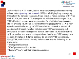
- 161. Display RIP Routers Router#sh ip route rip R 192.168.75.0/24 [120/5] via 172.30.0.2 00:00:25 serial 1/0 RIP Dest. n/w mask AD Metric Next Hop Timer own Interface RIP advanced configuration Passive Interfaces An interface, which is not able to send routing updates but able to receive routing update only is called Passive Interface. We can declare an interface as passive with following commands: Router#conf ter Router(config)#router rip Router(config-router)#Passive-interface <type> <no> Router(config-router)#exit 162
- 162. Neighbor RIP In RIP, by default routing updates are send to the address 255.255.255.255. In some scenarios, it may be required to send routing updates as a unicast from router to another. In this case, we have to configure neighbor RIP. For example: - in a Frame Relay n/w the broadcast update is discarded by the switches, so if we want to send RIP updates across the switches then we have to unicast updates using Neighbor RIP. 163
- 163. Unicast 10.0.0.2 255.255.255.255 10.0.0.1 Frame Relay Cloud 10.0.0.2 R1 R1 Router(config)#router rip Router(config-router)#neighbor 10.0.0.2 neighbor R2 R2 Router(config)#router rip Router(config router)# 10.0.0.1 164
- 164. To change Administrative Distance Router(config)#router rip Router(config-router)#distance <value> Router(config-router)#exit 95 or 100 To configure Load Balance RIP is able to perform equal path cost Load Balancing. If multiple paths are available with equal Hop Count for the destination then RIP will balance load equally on all paths. Load Balancing is enabled by default 4 paths. We can change the no. of paths. It can use simultaneously by following command: Router(config)#router rip Router(config-router)#maximum-path <1-6> 165
- 165. To display RIP parameters Router#sh ip protocol Or Router#sh ip protocol RIP This command display following parameters: (i) RIP Timers (ii) RIP Version (iii) Route filtering (iv) Route redistribution (v) Interfaces on which update send (vi) And receive (vii) Advertise n/w (viii) Passive interface (ix) Neighbor RIP (x) Routing information sources (xi) Administrative Distance 166
- 166. RIP version 2 RIP version 2 supports following new features: Support VLSM (send mask in updates) Multicast updates using address 224.0.0.9 Support authentication Commands to enable RIP version 2 We have to change RIP version 1 to RIP version 2. Rest all communication will remain same in RIP version 2. Router(config)#Router RIP Router(config-router)#version 2 Router(config-router)#exit 167
- 167. To debug RIP routing Router#debug ip rip To disable debug routing Router#no debug ip rip Or Router#no debug all Or Router#undebug all 168
- 168. Interior Gateway Routing Protocol Features: Cisco proprietary Distance vector Timers Update 90 sec Invalid 270 sec Hold time 280 sec Flush 630 sec Loop control All methods 169
- 169. Interior Gateway Routing Protocol Metric (24 bit composite) Bandwidth (default) Delay (default) Load Reliability MTU 170
- 170. Interior Gateway Routing Protocol Broadcast updates to address 255.255.255.255 Unequal path cost load balancing Automatic route summarization Support AS Does not support VLSM 171
- 171. Configuring IGRP Router(config)#router igrp <as no>(1 – 65535) Router(config-router)#network <net address> Router(config-router)#network <net address> Router(config-router)#exit Configuring Bandwidth on Interface for IGRP By default the router will detect maximum speed of interface and use this value as the bandwidth metric for IGRP. But it may be possible that the interfaces and working at its maximum speed then we have to configure bandwidth on interface, so that IGRP is able to calculate correct method 172
- 172. Router(config)#interface <type> <no> Router(config-if)#bandwidth <value in kbps> Router(config-if)#exit Router(config)#interface serial 0 Router(config-if)#bandwidth 256 Router(config-if)#exit Configuring Unequal path cost load balancing To configure load balancing, we have to set two parameters (1) Maximum path (by default 4) (2) Variance (default 1) Maximum Path: - it is maximum no. of paths that can be used for load balancing simultaneously. 173
- 173. Variance: - it is the multiplier value to the least metric for a destination n/w up to which the load can be balanced. Router(config)#Router igrp <as no> Router(config-router)#variance <value> Router(config-router)#exit 174
- 174. Configuring IGRP Configuring following options in IGRP as same as in case of RIP: Neighbor Passive interface Timer Distance (AD) Maximum path 175
- 175. Network Address Translation RFC-1631 A short term solution to the problem of the depletion of IP addresses Long term solution is IP v6 (or whatever is finally agreed on) CIDR (Classless Inter Domain Routing ) is a possible short term solution NAT is another NAT is a way to conserve IP addresses Hide a number of hosts behind a single IP address Use: • 10.0.0.0-10.255.255.255, • 172.16.0.0-172.32.255.255 or • 192.168.0.0-192.168.255.255 for local networks 176
- 176. Translation Modes Dynamic translation (IP masquerading) Large number of internal users share a single external address Static translation A block external addresses are translated to a same size block of internal addresses Load balancing translation A single incoming IP address is distributed across a number of internal servers Network redundancy translation Multiple internet connections are attached to a NAT firewall that it chooses and uses based on bandwidth, congestion and availability 177
- 177. Dynamic Translation (IP Masquerading ) Also called Network Address and Port Translation (NAPT) Individual hosts inside the Firewall are identified based on of each connection flowing through the firewall Since a connection doesn’t exist until an internal host requests a connection through the firewall to an external host, and most Firewalls only open ports only for the addressed host only that host can route back into the internal network IP Source routing could route back in; but, most Firewalls block incoming source routed packets NAT only prevents external hosts from making connections to internal hosts. Some protocols won’t work; protocols that rely on separate connections back into the local network Theoretical max of 216 connections, actual is much less 178
- 178. Static Translation Map a range of external address to the same size block of internal addresses Firewall just does a simple translation of each address Port forwarding - map a specific port to come through the Firewall rather than all ports; useful to expose a specific service on the internal network to the public network 179
- 179. Load Balancing A firewall that will dynamically map a request to a pool of identical clone machines often done for really busy web sites each clone must have a way to notify the Firewall of its current load so the Fire wall can choose a target machine or the firewall just uses a dispatching algorithm like round robin Only works for stateless protocols (like HTTP) 180
- 180. Network Redundancy Can be used to provide automatic fail-over of servers or load balancing Firewall is connected to multiple ISP with a masquerade for each ISP and chooses which ISP to use based on client load Kind of like reverse load balancing A dead ISP will be treated as a fully loaded one and the client will be routed through another ISP 181
- 181. Problems with NAT Can’t be used with: Protocols that require a separate back-channel Protocols that encrypt TCP headers Embed TCP address info Specifically use original IP for some security reason 182
- 182. Working of NAT & PAT 10.0.0.5 10.0.0.6 10.0.0.1 NAT 200.100.100.12 Internet Switch 10.0.0.5 10.0.0.7 200.100.100.12 1080 10.0.0.8 10.0.0.6 200.100.100.12 1085 183
- 184. Static NAT This NAT is also used for servers. It provides port-based access to the servers with the help of NAT. Static NAT 200.1.1.5 = 192.168.10.6 Router Internet .1.5 200.1 Live Local 192.168.10.6 185
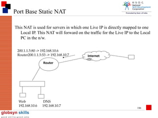
- 185. Port Base Static NAT This NAT is used for servers in which one Live IP is directly mapped to one Local IP. This NAT will forward on the traffic for the Live IP to the Local PC in the n/w. 200.1.1.5:80 -> 192.168.10.6 Router200.1.1.5:53 -> 192.168.10.7 Internet Router Web 192.168.10.6 DNS 192.168.10.7 186
- 186. Dynamic NAT using Pool Dynamic NAT is used for clients, which want to access Internet. The request from multiple client IPs are translated with the Live IP obtained from the Pool. It is also called Pool Based Dynamic NAT. Pool => 200.1.1.8 – 200.1.1.12/28 Internet Local address => 172.16.X.X Except => 172.16.0.5 172.16.0.6 172.16.0.7 Pool allotted => 200.1.1.0 – 15/28 Server Static => 200.1.1.3 = 172.16.0.7 Port Based Static NAT 200.1.1.4:53 = 172.16.0.6 200.1.1.4:80 = 172.16.0.5 187
- 187. Dynamic NAT using Pool Client Dynamic NAT Pool => 200.1.1.8 – 200.1.1.12/28 Local address => 172.16.0.X Except 172.16.0.5 172.16.0.6 172.16.0.7 188
- 188. Configuring NAT Router#conf ter Router(config)#int serial 0 Router(config-if)#ip nat outside Router(config-if)#int eth 0 Router(config-if)#ip nat inside Router(config-if)#exit Router(config)#ip nat inside source static 172.16.0.7 200.1.1.3 Router(config)#ip nat inside source static tcp 172.16.0.5 80 200.1.1.4 80 Router(config)#ip nat inside source static udp 172.16.0.6 53 200.1.1.4 53 Router(config)#access-list 30 deny 172.16.0.5 Router(config)#access-list 30 deny 172.16.0.6 Router(config)#access-list 30 deny 172.16.0.7 Router(config)#access-list 30 permit any Router(config)#ip nat pool abc 200.1.1.8 200.1.1.12 netmask 189 255.255.255.240
- 189. Command for Basic NAT Router(config)#ip nat inside source list 30 interface serial 0 <exiting interface name> To display NAT translation Router#sh ip nat translations (after ping any address, it shows ping details) To clear IP NAT Translation Router#clear ip nat Translation * 190
- 190. Document Amendment History Document Amendment History S.No Description Author Version Date 1 2 3 4 5 6 7 8 191
- 191. T H A N K Y O U. . . All information, including graphical representations, etc provided in this presentation is for exclusive use of current Globsyn Skills students and faculty. No part of the document may be reproduced in any form or by any means, electronic or otherwise, without written permission of the owner. 192
- 192. SKILLS FOR INDIA Remote Access Mode
- 193. Remote Access Service Remote Access Services (RAS) refers to any combination of hardware and software to enable the remote access tools or information that typically reside on a network of IT devices. A RAS server is a specialized computer which aggregates multiple communication channels together. Because these channels are bidirectional, two models emerge: Multiple entities connecting to a single resource, and a single entity connecting to multiple resources. Both of these models are widely used. Both physical and virtual resources can be provided through a RAS server: centralized computing can provide multiple users access to a remote virtual operating system. Access Providers often use RAS servers to terminate physical connections to their customers, for example customers who get Internet through some form of modem. Originally coined by Microsoft when referring to their built-in NT remote access tools, RAS was a service provided by Windows NT which allows most of the services which would be available on a network to be accessed over a modem link. 194
- 194. The service includes support for dialup and logon, presents the same network interface as the normal network drivers (albeit slightly slower). It is not necessary to run Windows NT on the client - there are client versions for other Windows operating systems. A feature built into Windows NT enables users to log into an NTbased LAN using a modem, X.25 connection or WAN link. RAS works with several major network protocols, including TCP/IP, IPX, and NBF. To use RAS from a remote node, you need a RAS client program, which is built into most versions of Windows, or any PPP client software. For example, most remote control programs work with RAS. Starting in the mid-1990s, several manufacturers such as U.S. Robotics produced "modem terminal servers". Instead of having RS232ports, these would directly incorporate an analog modem. These devices were commonly used by Internet service providers to allow consumer dialup. Modern versions interface to an ISDN PRI instead of having analog modem ports. 195
- 195. Complete these steps to configure RAS on a Cisco ICM Logger. Select Start > Settings > Control Panel Double-click the Network Applet Select Services Double-click the Remote Access Service 196
- 196. Figure 1: Remote Access Setup 197
- 197. Click Configure. Figure 2: Configure Port Usage 198
- 198. Media Access Methods An access method is a set of rules governing how the network nodes share the transmission medium. The rules for sharing among computers are similar to the rules for sharing among humans in that they both boil down to a pair of fundamental philosophies: first come, first served and take turns. These philosophies are the principles defining the three most important types of media access methods: 199
- 199. Media Access Methods Contention. -(CSMA/CD Carrier Sense Multiple Access with Collision Detection, -CSMA/CA Carrier Sense Multiple Access with Collision Avoidance) Token passing. Demand Priority. 200
- 200. Contention CSMA/CD Carrier Sense Multiple Access with Collision Detection IEEE 802.3 Ethernet LANs use the Carrier Sense Multiple Access with Collision detection(CSMA/CD) protocol to detect and handle collisions on the network. However, WLANs can’t use CSMA/CD because they can’t transmit and listen at the same time. CSMA/CA Carrier Sense Multiple Access with Collision Avoidance The IEEE 802.11b standard specifies the carrier sense multiple access with collision avoidance (CSMA/CA) protocol for WLANs. CSMA/CA tries to avoid collisions by using explicit packet acknowledgment. With CSMA/CA, an acknowledgment packet is sent by the receiving station to confirm it has received a data packet. If the transmitting station does not receive the acknowledgment, it assumes that a collision has occurred and transmits the data packet again. 201
- 201. Token passing IEEE 802.5 standard deals with Token Ring networks Token passing is implemented on a token-ring network. IEEE 802.5 Token Ring networks use a token-passing media access method. A token is a special packet that gives permission to a device to transmit data on to the network. When a device receives a token and transmits a frame, the frame is forwarded around the ring by all attached devices. When the frame reaches its destination, it is copied and processed by the receiving device and placed back on the ring. Before placing the frame back on the ring, the receiving device sets frame-status bits to indicate that the frame was received. The frame circles the ring until it returns to the original transmitting device. 202
- 202. Demand Priority Demand priority is an access method used with the new 100Mbps 100VG-AnyLAN standard. Although demand priority is officially considered a contention-based access method, demand priority is considerably different from the basic CSMA/CD Ethernet. In demand priority, network nodes are connected to hubs, and those hubs are connected to other hubs. Contention, therefore, occurs at the hub. (100VG-AnyLAN cables can actually send and receive data at the same time.) Demand priority provides a mechanism for prioritizing data types. If contention occurs, data with a higher priority takes precedence 203
- 203. Collision & Broadcast Domains MAC Address Contains 48-bit destination address field. Who is this frame for? 00-C0-F0-56-BD-97 “Hey Joe” 204
- 204. MAC Address How will all other NICs handle the frame? Drop it (in the “bit bucket”) 205
- 205. Special MAC Address Who is this frame for? FF-FF-FF-FF-FF-FF “Hey everybody” 206
- 206. Broadcast MAC Address FF-FF-FF-FF-FF-FF 48 bits, all 1s All NICs copy the frame & send it up the stack 207
- 207. Broadcast Frames Necessary for network function Used for finding services: “Hey, is there a server out there?” Advertising services: “Hey, I’m a printer you can use.” Some Layer 3 (Network Layer) protocols use broadcasts frequently: Appletalk IPX (older Novell protocol) Networks that use these protocols must be limited in size, or they will become saturated with broadcast frames. TCP/IP (a Layer 3 protocol) uses broadcasts sparingly. Therefore, networks that use TCP/IP can be made quite large without broadcast problems. (They “scale” well.) 208
- 208. Collision Domain Network region in which collisions are propagated. Repeaters and hubs propagate collisions. Bridges, switches and routers do not.
- 209. Reducing Collisions Collision frequency can be kept low by breaking the network into segments bounded by: bridges switches routers
- 210. Broadcast Domain Network region in which broadcast frames are propagated. Repeaters, hubs, bridges, & switches propagate broadcasts. Routers either do or don’t, depending on their configuration.
- 211. Reducing Broadcasts Broadcasts are necessary for network function. Some devices and protocols produce lots of broadcasts; avoid them. Broadcast frequency can be kept manageable by limiting the LAN size. LANs can then be cross-connected by routers to make a larger internetwork.
- 212. Shared Ethernet A single segment that is shared among all connected NICs. A single collision domain. A logical “bus” (may be a physical star). The segment includes repeaters and hubs. Sometimes called a “single flat Ethernet”.
- 213. Shared Ethernet Hub
- 214. Switched Ethernet Consists of a several segments, each of which is shared by NICs attached to it. The network is segmented into several collision domains. Bridges, switches, and routers create the segment and collision domain boundaries. Segments may contain hubs and repeaters.
- 215. Switched Ethernet Switch - 1 port per hub Hub Hub
- 216. Micro segmented Switched Ethernet Each user NIC is connected directly to a switch port. Provides one switched segment to each connected NIC. No sharing. No collisions.
- 217. Micro segmented Switched Ethernet Switch - 1 port per PC
- 218. Summary Term LAN Segment (Collision domain) Entire LAN (Broadcast domain) Internetwork (Group of LANs cross-connected by Routers) Includes Cable Repeaters Hubs Boundary Bridges Switches (Routers) Everything except Routers Edge of LAN Routers LANs & Routers Edge of Internetwork Example switch router switch
- 219. Identify the collision domains & broadcast domains switch hub hub
- 220. Identify the collision domains & broadcast domains hub hub
- 221. Identify the collision domains & broadcast domains switch hub
- 222. Identify the collision domains & broadcast domains: router switch Router connects separate networks. One broadcast domain per router interface.
- 223. Application First, complete Lab 7A Then, on a printed copy of the “Teaching Topology” (curriculum p7.5.5) Circle each collision domain - use a solid line. Circle each broadcast domain - use a dashed line.
- 224. Reminder Collisions spread throughout a LAN segment spread across hubs & repeaters are stopped by switches & bridges Broadcasts spread throughout an entire LAN spread across hubs, switches, bridges are stopped only by routers 225
- 225. LAN Switching Ethernet switches are used in LAN to create Ethernet n/ws. Switches forward the traffic on the basis of MAC address. Switches maintain a Mac Addresse table in which mac addresses and port no.s are used to perform switching decision. Working of bridge and switch is similar to each other. 226
- 226. Classification of switches Switches are classified according to the following criteria: Types of switches based on working (1) Store & Forward This switch receives entire frame then perform error checking and start forwarding data to the destination. (2) Cut through This switch starts forwarding frame as soon as first six bytes of the frame are received. (3) Fragment-free This switch receives 64 bytes of the frame, perform error checking and then start forwarding data. (4) Adaptive cut-through It changes its mode according the condition. If it see there are errors in many frames then it changes to Store & Forward mode from Cut through or Fragment-free. 227
- 227. Classification of switches Types of switches based on management (1) Manageable switches (2) Non-Manageable switches (3) Semi-Manageable switches Types of switches based on OSI layer (1) Layer 2 switches (only switching) (2) Layer 3 switches (switching & routing) Types of switches based on command mode (only in Cisco) (1) IOS based (2) CLI based Type of switches based on hierarchical model (1) Core layer switches (2) Distribution layer switches (3) Access layer switches 228
- 228. Basic Switch Administration IOS based switches are similar to the routers. We can perform following function on switches in a similar manner as performed on router. (1) Access switch using console (2) Commands to enter & exit from different mode (3) Commands to configure passwords (4) Manage configuration (5) Backup IOS and configuration (6) Configuring and resolving hostnames (7) Managing telnet (8) Configuring CDP (9) Configuring time clock (10) Configuring Banners (11) Command line shortcuts and editing shortcuts (12) Managing history (13) Configure logging (14) Boot system commands 229
- 229. Basic Switch Administration Following function and options are not similar in router and switch. (1) Default hostname is ‘Switch’ (2) Auxiliary port is not present (3) VTY ports are mostly 0 to 15 (4) By default interfaces are enabled (5) IP address cannot be assign to interfaces (6) Routing configuration mode is not present (7) Interface no. starts from 1 (8) Web access is by default enabled (9) Configuration registry is not present in similar manner (10) Flash memory may contain multiple files and startup-configuration is also saved in flash 230
- 230. Configuring IP and Gateway on switch We can configure IP address on switch for web access or telnet IP address is required for the administration of the switch. If we have to access switch from remote n/w then we will configure default gateway in addition to IP address. IP address is assigned to the logical interface of switch with following command:Switch(config)#interface vlan 1 Switch(config)#IP address <ip> <mask> Switch(config)#no sh Switch(config)#exit 231
- 231. Old Switches Switch(config)#ip address <ip> <mask> Switch(config)#exit Configuring Gateway Switch(config)#ip default-gateway <ip> Switch(config)#exit 232
- 232. Breaking Switch Password (1) Power off switch press mode button present in front of switch then power on the switch. (2) Keep mode button press until ‘Switch:’ prompt appears on console. (3) In switch monitor mode, type following commands: flash_init load_helper rename flash:config.text flash:<anyname> dir flash: boot (4) After booting switch will prompt to enter in initial configuration dialog. Enter ‘no’ here and type. Switch>enable Rename flash:<anyname> Flash:config.text Configure memory Change password and save config. Then copy run start_config. 233
- 233. Document Amendment History Document Amendment History S.No Description Author Version Date 1 2 3 4 5 6 7 8 234
- 234. T H A N K Y O U. . . All information, including graphical representations, etc provided in this presentation is for exclusive use of current Globsyn Skills students and faculty. No part of the document may be reproduced in any form or by any means, electronic or otherwise, without written permission of the owner. 235
- 235. SKILLS FOR INDIA Security Protocol
- 236. A security protocol (cryptographic protocol or encryption protocol) is an abstract or concrete protocol that performs a security-related function and applies cryptographic methods. A protocol describes how the algorithms should be used. A sufficiently detailed protocol includes details about data structures and representations, at which point it can be used to implement multiple, interoperable versions of a program. Cryptographic protocols are widely used for secure application-level data transport. A cryptographic protocol usually incorporates at least some of these aspects: Key agreement or establishment Entity authentication Symmetric encryption and message authentication material construction Secured application-level data transport Non-repudiation methods 237
- 237. Internet Key Exchange Internet Key Exchange (IKE or IKEv2) is the protocol used to set up a security association (SA) in the IPSec protocol suite. IKE builds upon the Oakley protocol and ISAKMP. IKE uses X.509 certificates for authentication which are either pre-shared or distributed using DNS (preferably with DNSSEC), and a Diffie–Hellman key exchange to set up a shared session secret from which cryptographic keys are derived. In addition, a security policy for every peer which will connect must be manually maintained 238
- 238. IPsec Internet Protocol Security (IPsec) is a protocol suite for securing Internet Protocol (IP) communications by authenticating andencrypting each IP packet of a communication session. IPsec also includes protocols for establishing mutual authentication between agents at the beginning of the session and negotiation of cryptographic keys to be used during the session. IPsec is an end-to-end security scheme operating in the Internet Layer of the Internet Protocol Suite. It can be used in protecting data flows between a pair of hosts (host-to-host), between a pair of security gateways (networkto-network), or between a security gateway and a host (network-to-host).[1] Some other Internet security systems in widespread use, such as Secure Sockets Layer (SSL), Transport Layer Security (TLS) andSecure Shell (SSH), operate in the upper layers of the TCP/IP model. In the past, the use of TLS/SSL had to be designed into an application to protect the application protocols. In contrast, since day one, applications did not need to be specifically designed to use IPsec. 239
- 239. Hence, IPsec protects any application traffic across an IP network. This holds true now for SSL as well with the rise of SSL based VPN revolution with implementations like OpenVPN. IPsec originally was developed at the Naval Research Laboratory as part of a DARPA-sponsored research project. ESP was derived directly from the SP3D protocol, rather than being derived from the ISO Network-Layer Security Protocol (NLSP). The SP3D protocol specification was published by NIST, but designed by the Secure Data Network System project of the National Security Agency (NSA), IPsec AH is derived in part from previous IETF standards work for authentication of the Simple Network Management Protocol (SNMP). IPsec is officially specified by the Internet Engineering Task Force (IETF) in a series of Request for Comments documents addressing various components and extensions. It specifies the spelling of the protocol name to be IPsec 240
- 240. Kerberos (protocol) Kerberos is a computer network authentication protocol which works on the basis of "tickets" to allow nodes communicating over a non-secure network to prove their identity to one another in a secure manner. Its designers aimed primarily at a client–server model, and it provides mutual authentication—both the user and the server verify each other's identity. Kerberos protocol messages are protected against eavesdropping and replay attacks. Kerberos builds on symmetric key cryptography and requires a trusted third party, and optionally may use public-key cryptography by utilizing asymmetric key cryptography during certain phases of authentication. Kerberos uses port 88 by default. "Kerberos" also refers to a suite of free software published by Massachusetts Institute of Technology (MIT) that implements the Kerberos protocol. 241
- 241. Point-to-point protocol In networking, the Point-to-Point Protocol (PPP) is a data link protocol commonly used in establishing a direct connection between two networking nodes. It can provide connection authentication, transmission encryption (using ECP, RFC 1968), and compression. PPP is used over many types of physical networks including serial cable, phone line, trunk line, cellular telephone, specialized radio links, and fiber optic links such as SONET. PPP is also used over Internet access connections (now marketed as "broadband"). Internet service providers (ISPs) have used PPP for customer dial-up access to the Internet, since IP packets cannot be transmitted over a modem line on their own, without some data link protocol. Two encapsulated forms of PPP, Point-toPoint Protocol over Ethernet (PPPoE) and Point-to-Point Protocol over ATM (PPPoA), are used most commonly by Internet Service Providers (ISPs) to establish a Digital Subscriber Line (DSL) Internet service connection with customers. 242
- 242. PPP is commonly used as a data link layer protocol for connection over synchronous and asynchronous circuits, where it has largely superseded the older Serial Line Internet Protocol (SLIP) and telephone company mandated standards (such as Link Access Protocol, Balanced (LAPB) in the X.25 protocol suite). PPP was designed to work with numerous network layer protocols, including Internet Protocol (IP), TRILL, Novell's Internetwork Packet Exchange (IPX), NBF and AppleTalk. 243
- 243. Transport Layer Security Transport Layer Security (TLS) and its predecessor, Secure Sockets Layer (SSL), are cryptographic protocols that provide communication security over the Internet. TLS and SSL encrypt the segments of network connections at the Application Layer for the Transport Layer, using asymmetric cryptography for key exchange, symmetric encryption for privacy, and message authentication codes for message integrity. Several versions of the protocols are in widespread use in applications such as web browsing, electronic mail, Internet faxing, instant messaging and voice-over-IP (VoIP). TLS is an IETF standards track protocol, last updated in RFC 5246, and is based on the earlier SSL specifications developed by Netscape Communications. 244
- 244. Wireless Technology Wireless telecommunications is the transfer of information between two or more points that are not physically connected. Distances can be short, such as a few meters for television remote control, or as far as thousands or even millions of kilometers for deep-space radio communications. It encompasses various types of fixed, mobile, and portable two-way radios, cellular telephones, personal digital assistants (PDAs), and wireless networking. Other examples of wireless technology include GPS units, Garage door openers or garage doors, wireless computer mice, keyboards and Headset (audio), headphones, radio receivers,satellite television, broadcast television and cordless telephones. 245
- 245. Infrared Infrared (IR) light is electromagnetic radiation with longer wavelengths than those of visible light, extending from the nominal red edge of the visible spectrum at 0.74 micrometers (µm) to 300 µm. This range of wavelengths corresponds to a frequency range of approximately 1 to 400 THz, and includes most of the thermal radiation emitted by objects near room temperature. Infrared light is emitted or absorbed by molecules when they change their rotationalvibrational movements. Much of the energy from the Sun arrives on Earth in the form of infrared radiation. Sunlight at zenith provides an irradiance of just over 1 kilowatt per square meter at sea level. Of this energy, 527 watts is infrared radiation, 445 watts is visible light, and 32 watts is ultraviolet radiation. The balance between absorbed and emitted infrared radiation has a critical effect on the Earth's climate. 246
- 246. Infrared light is used in industrial, scientific, and medical applications. Night-vision devices using infrared illumination allow people or animals to be observed without the observer being detected. In astronomy, imaging at infrared wavelengths allows observation of objects obscured by interstellar dust. Infrared imaging cameras are used to detect heat loss in insulated systems, observe changing blood flow in the skin, and overheating of electrical apparatus. 247
- 247. Light Comparison[3] Name Wavelength Frequency (Hz) Photon Energy (eV) Gamma ray less than 0.01 nm more than 10 EHZ 100 keV - 300+ GeV X-Ray 0.01 nm to 10 nm 30 EHz - 30 PHZ 120 eV to 120 keV Ultraviolet 10 nm - 390 nm 30 PHZ - 790 THz 3 eV to 124 eV Visible 390 - 750 nm 790 THz - 405 THz 1.7 eV - 3.3 eV Infrared 750 nm - 1 mm 405 THz - 300 GHz 1.24 meV - 1.7 eV Microwave 1 mm - 1 meter 300 GHz - 300 MHz 1.24 µeV - 1.24 meV Radio 1 mm - 100,000 km 300 GHz - 3 Hz 12.4 feV - 1.24 meV 248
- 248. Bluetooth What is the Bluetooth? Radio modules operate in 2.45GHz. RF channels:2420+k MHz Devices within 10m of each other can share up to 1Mbps Projected cost for a Bluetooth chip is ~$5. Its low power consumption Can operate on both circuit and packet switching modes Providing both synchronous and asynchronous data services Bluetooth IEEE 802.11A UWB frequency 2.4Ghz 5GHz 3.1~10.6GHz MAX data rate 1Mbps 54Mbps 100Mbps~1Gbps Range 5~10m 35~50m 10~30m The number of channel 79 12 ….. 249
- 249. Bluetooth versions Bluetooth 1.0 and 1.0B Versions 1.0 and 1.0B had many problems • Manufacturers had difficulty making their products interoperable Bluetooth 1.1 Many errors found in the 1.0B specifications were fixed Added support for non-encrypted channels Received Signal Strength Indicator (RSSI) Bluetooth 1.2 Faster Connection and Discovery Use the Adaptive frequency-hopping spread spectrum (AFH) • Improves resistance to radio frequency interference Higher transmission speeds in practice, up to 721 kbps 250
- 250. Bluetooth 2.0 This version, specified November 2004 The main enhancement is the introduction of an enhanced data rate (EDR) of 3.0 Mbps. Lower power consumption through a reduced duty cycle. Simplification of multi-link scenarios due to more available bandwidth. Bluetooth 2.1 A draft version of the Bluetooth Core Specification Version 2.1 + EDR is now available 251
- 251. Ultra Wide Band(UWB) What is the UWB? Transmitting information spread over a large bandwidth (>500 MHz) Provide an efficient use of scarce radio bandwidth • High data rate in WPAN connectivity and longer-range A February 14, 2002 • Report and Order by the FCC authorizes the unlicensed use of UWB November of 2005 • ITU-R have resulted in a Report and Recommendation on UWB Expected to act on national regulations for UWB very soon 252
- 252. Advantage of the UWB Take advantage of inverse relationship between distance and throughput Huge bandwidth : very high throughput Low power consumption Convenience and flexibility No interference 253
- 253. Ultra Wide Band(UWB) Current wireless Comparison Wireless technology Power mW Rage meter BW/channel Rate bps CDMA 1xEVDO 600 ~2000 1.25 MHz 2.4M 802.16(WiMAX ) 250 ~4000 25MHz 120M 802.11g(WiFi) 50 ~100 25MHz 54M Bluetooth 1 ~10 1MHz <1M UWB <30 10~30 500MHz 100M~1G Key application Wireless USB Toys and game Consumer electronics Location tracking Handset 254
- 254. Factors Affecting Wireless Signals Because wireless signals travel through the atmosphere, they are susceptible to different types of interference than standard wired networks. Interference Types The following are some factors that cause interference: Physical objects: Trees, masonry, buildings, and other physical structures are some of the most common sources of interference. The density of the materials used in a building’s construction determines the number of walls the RF signal can pass through and still maintain adequate coverage. Concrete and steel walls are particularly difficult for a signal to pass through. These structures will weaken or at times completely prevent wireless signals. 255
- 255. Radio frequency interference: Wireless technologies such as 802.11b/g use an RF range of 2.4GHz, and so do many other devices, such as cordless phones, microwaves, and so on. Devices that share the channel can cause noise and weaken the signals. Electrical interference: Electrical interference comes from devices such as computers, refrigerators, fans, lighting fixtures, or any other motorized devices. The impact that electrical interference has on the signal depends on the proximity of the electrical device to the wireless access point. Advances in wireless technologies and in electrical devices have reduced the impact that these types of devices have on wireless transmissions. Environmental factors: Weather conditions can have a huge impact on wireless signal integrity. Lightning, for example, can cause electrical interference, and fog can weaken signals as they pass through. 256
- 256. How to Install a Wireless Router to Share DSL Internet It makes no difference to a router whether your Internet arrives through DSL or cable; it will work just the same. By installing a wireless router, you can easily share your Internet connection among multiple computers and enjoy connectivity without the constraints of cables or wires. 257
- 257. Step 1 Attach the incoming DSL cable to the "Input," "Cable" or "DSL" port on your DSL modem. Step 2 Plug one end of an Ethernet cable into the Ethernet port on your DSL modem and plug the other end of the cable into the "Internet," "WLAN" or "WAN" port on your wireless router. Step 3 Plug one end of the Ethernet cable supplied with your wireless router into one of the output ports on the router. Plug the other end of the cable into the Ethernet port on your computer. Step 4 Connect your DSL modem and router to a power source. 258
- 258. Step 5 Open a browser and type the router's IP address, which likely will be either "http://192.168.0.1" or "http://192.168.1.1." Enter the username, which is frequently "admin." Enter the password, which may be set to "admin", "password" or blank as the default. Set up the router according to the instructions provided with the router. The product documentation will also provide the IP address and username/password. During setup, the most important things you should do are change the SSID network name, configure encryption and change the router password. Step 6 Disconnect the Ethernet cable from your computer, if you prefer to connect wirelessly. Step 7 Click the wireless icon, located by the system clock on your Windows 7 PC. Click the router name that corresponds to the SSID you entered during setup. Click "Connect" and enter the password to connect to the router. Repeat for each computer requiring access. 259
- 259. Configuring a Wireless Access Point When you access the configuration page of your wireless access point on the Internet, you have the following configuration options that are related to the wireless access point functions of the device. Although these options are specific to this particular device, most access points have similar configuration options. Enable/Disable: Enables or disables the device's wireless access point functions. SSID: The Service Set Identifier used to identify the network. Most access points have well-known defaults. You can talk yourself into thinking that your network is more secure by changing the SSID from the default to something more obscure, but in reality, that only protects you from firstgrade hackers. By the time most hackers get into the second grade, they learn that even the most obscure SSID is easy to get around. 260
- 260. Allow broadcast SSID to associate? Disables the access point's periodic broadcast of the SSID. Normally, the access point regularly broadcasts its SSID so that wireless devices that come within range can detect the network and join in. For a more secure network, you can disable this function. Then, a wireless client must already know the network's SSID in order to join the network. Channel: Lets you select one of 11 channels on which to broadcast. All the access points and computers in the wireless network should use the same channel. If you find that your network is frequently losing connections, try switching to another channel. You may be experiencing interference from a cordless phone or other wireless device operating on the same channel. WEP — Mandatory or Disable: Lets you use a security protocol called wired equivalent privacy. 261
- 261. Troubleshooting Wireless Network Connections Check the wires and wireless network adapter Checking that all your wires are plugged in at the router and from the plug is one of the first things you should do – provided of course that you have access to them. Verify that the power cord is connected and that all the lights of the router and cable/DSL modem are on. This may seem like a ridiculous suggestion but you should never disregard the obvious. You’d be surprised at how your configuration can be perfect, and after a while of playing around with settings you realize that the network cable leading from the router to the cable modem has come undone slightly. 262
- 262. Driver Compatibility It is important to make sure that you have installed the correct device driver for your wireless network adapter. This can cause all sorts of problems or your adapter not to function at all. A friend of mine recently set up his own wireless network at home but complained to me that his wireless network connection was going “crazy”. Upon inspection I realized that he had configured his router properly but installed the 5v instead of the 3v driver on his laptop PCMCIA network card. Once the correct driver was installed, everything began to run smoothly. It just goes to show how even the smallest detail can make all the difference so make sure you have the correct driver installed! 263
- 263. Low Signal Strength There are a number of factors that can cause the signal of your access point to deteriorate and the performance of your network to fall under par. Practically any appliance that operates on the same frequency level (2.4 GHz) as 802.11b or 802.11g can cause interference with your wireless network. Be sure to keep cordless phones, microwaves and other electrical equipment at least 1m away from the access point. Try changing channels on the access point and test it out on one of the clients. To change the radio channel on the access point login to the configuration (usually a web based interface) and go to the Wireless Settings (will vary depending on vendor) section, select a different channel and save settings. On the client, go to Device Manager, right click your wireless network adapter and go to Properties. 264
- 264. In the advanced tab select the Channel Property and change the Value to the same number as the one you chose on the Access Point. Disable and then re-enable the wireless connection. 265
- 265. Access Point Location You may also want to try changing the position of your access point antenna to improve performance. Play around with its position and see if you notice a difference. I find that if I point the antenna sideways or downwards I have better reception on the floor below. The following images demonstrate what I mean. Antenna pointing upwards (default) Antenna pointing sideways 266
- 266. Access Point Location The location of your access point is vital. Try and place it in a central location, as much as possible avoiding physical obstructions and reflective surfaces. Remember that wireless signals bounce of windows and mirrors, thus decreasing the range. Experiment with different locations until you find one that is practical and promising. Most people, including myself, like placing it near the ceiling since most obstructions are nearer to the floor. It’s always a good idea to monitor the performance of your signal by using a diagnostic utility. This will help you to identify how strong your signal is in different locations and whether other electrical equipment is interfering. Run the utility when the microwave or cordless phone is in use and see if you notice a difference. Usually your access point will come with its own monitoring utility. 267
- 267. Document Amendment History Document Amendment History S.No Description Author Version Date 1 2 3 4 5 6 7 8 268
- 268. T H A N K Y O U. . . All information, including graphical representations, etc provided in this presentation is for exclusive use of current Globsyn Skills students and faculty. No part of the document may be reproduced in any form or by any means, electronic or otherwise, without written permission of the owner. 269
- 269. SKILLS FOR INDIA Proxy Server
- 270. Proxy Server In computer networks, a proxy server is a server (a computer system or an application) that acts as an intermediary for requests from clients seeking resources from other servers. A client connects to the proxy server, requesting some service, such as a file, connection, web page, or other resource available from a different server. The proxy server evaluates the request as a way to simplify and control their complexity. Today, most proxies are web proxies, facilitating access to content on the World Wide Web. 271
- 271. Utility of a Proxy server To keep machines behind it anonymous, mainly for security To speed up access to resources (using caching). Web proxies are commonly used to cache web pages from a web server To apply access policy to network services or content, e.g. to block undesired sites To access sites prohibited or filtered by your ISP or institution To log / audit usage, i.e. to provide company employee Internet usage reporting To bypass security / parental controls To circumvent Internet filtering to access content otherwise blocked by government To scan transmitted content for malware before delivery To scan outbound content, e.g., for data loss prevention To allow a web site to make web requests to externally hosted resources (e.g. images, music files, etc.) when cross-domain restrictions prohibit the 272 web site from linking directly to the outside domains
- 272. Types of proxy Forward proxies Open proxies Reverse proxies 273
- 273. Forward proxies Forward proxies are proxies where the client server names the target server to connect to. Forward proxies are able to retrieve from a wide range of sources (in most cases anywhere on the Internet). The terms "forward proxy" and "forwarding proxy" are a general description of behavior (forwarding traffic) and thus ambiguous. Except for Reverse proxy, the types of proxies described in this article are more specialized subtypes of the general forward proxy concept. 274
- 274. Open proxies An open proxy is a forwarding proxy server that is accessible by any Internet user. Gordon Lyon estimates there are "hundreds of thousands" of open proxies on the Internet. An anonymous open proxy allows users to conceal their IP address while browsing the Web or using other Internet services. There are varying degrees of anonymity however, as well as a number of methods of 'tricking' the client into revealing itself regardless of the proxy being used. 275
- 275. Reverse proxies A reverse proxy (or surrogate) is a proxy server that appears to clients to be an ordinary server. Requests are forwarded to one or more origin servers which handle the request. The response is returned as if it came directly from the proxy server. Reverse proxies are installed in the neighborhood of one or more web servers. All traffic coming from the Internet and with a destination of one of the neighborhood's web servers goes through the proxy server. The use of "reverse" originates in its counterpart "forward proxy" since the reverse proxy sits closer to the web server and serves only a restricted set of websites. 276
- 276. Issues with Proxy Server The diversion / interception of a TCP connection creates several issues. Firstly the original destination IP and port must somehow be communicated to the proxy. This is not always possible (e.g. where the gateway and proxy reside on different hosts). There is a class of cross site attacks that depend on certain behavior of intercepting proxies that do not check or have access to information about the original (intercepted) destination. This problem can be resolved by using an integrated packet-level and application level appliance or software which is then able to communicate this information between the packet handler and the proxy. Intercepting also creates problems for HTTP authentication, especially connection-oriented authentication such as NTLM, since the client browser believes it is talking to a server rather than a proxy. This can cause problems where an intercepting proxy requires authentication, then the user connects to a site which also requires authentication. 277
- 277. Issues with Proxy Server Finally intercepting connections can cause problems for HTTP caches, since some requests and responses become un cacheable by a shared cache. Therefore intercepting connections is generally discouraged. However due to the simplicity of deploying such systems, they are in widespread use. 278
- 278. Document Amendment History Document Amendment History S.No Description Author Version Date 1 2 3 4 5 6 7 8 279
- 279. T H A N K Y O U. . . All information, including graphical representations, etc provided in this presentation is for exclusive use of current Globsyn Skills students and faculty. No part of the document may be reproduced in any form or by any means, electronic or otherwise, without written permission of the owner. 280
- 280. SKILLS FOR INDIA Virtual LAN
- 281. A virtual local area network, virtual LAN or VLAN, is a group of hosts with a common set of requirements, which communicate as if they were attached to the same broadcast domain, regardless of their physical location. A VLAN has the same attributes as a physical local area network (LAN), but it allows for end stations to be grouped together even if not on the same network switch. VLAN membership can be configured through software instead of physically relocating devices or connections. To physically replicate the functions of a VLAN would require a separate, parallel collection of network cables and equipment separate from the primary network. However, unlike a physically separate network, VLANs must share bandwidth; two separate one-gigabit VLANs that share a single one-gigabit interconnection can suffer reduced throughput and congestion. It virtualizes VLAN behaviors (configuring switch ports, tagging frames when entering VLAN, lookup MAC table to switch/flood frames to trunk links, and un tagging when exit from VLAN.) 282
- 282. Types Of VLANs Today there is essentially one way of implementing VLANs - port-based VLANs. A port-based VLAN is associated with a port called an access VLAN. However in the network there are a number of terms for VLANs. Some terms define the type of network traffic they carry and others define a specific function a VLAN performs. The following describes common VLAN terminology: Data VLAN Default VLAN Native VLAN Management VLAN Voice VLANs 283
- 283. Utility of VPN VLANs are created to provide the segmentation services traditionally provided by routers in LAN configurations. VLANs address issues such as scalability, security, and network management. Routers in VLAN topologies provide broadcast filtering, security, address summarization, and traffic flow management. By definition, switches may not bridge IP traffic between VLANs as it would violate the integrity of the VLAN broadcast domain. This is also useful if someone wants to create multiple layer 3 networks on the same layer 2 switch. For example, if a DHCP server is plugged into a switch it will serve any host on that switch that is configured to get its IP from a DHCP server. By using VLANs you can easily split the network up so some hosts won't use that DHCP server and will obtain link-local addresses, or obtain an address from a different DHCP server. 284
- 284. Advantages of VLAN The main advantages of VLAN are listed below. Broadcast Control: Broadcasts are required for the normal function of a network. Many protocols and applications depend on broadcast communication to function properly. A layer 2switched network is in a single broadcast domain and the broadcasts can reach the network segments which are so far where a particular broadcast has no scope and consume available network bandwidth. A layer 3 device (typically a router) is used to segment a broadcast domain. If we segment a large LAN to smaller VLANs we can reduce broadcast traffic as each broadcast will be sent on to the relevant VLAN only 285
- 285. Security: VLANs provide enhanced network security. In a VLAN network environment, with multiple broadcast domains, network administrators have control over each port and user. A malicious user can no longer just plug their workstation into any switch port and sniff the network traffic using a packet sniffer. The network administrator controls each port and whatever resources it is allowed to use. VLANs help to restrict sensitive traffic originating from an enterprise department within itself. Cost: Segmenting a large VLAN to smaller VLANs is cheaper than creating a routed network with routers because normally routers costlier than switches Physical Layer Transparency: VLANs are transparent on the physical topology and medium over which the network is connected 286
- 286. VLAN provides Virtual Segmentation of Broadcast Domain in the network. The devices, which are member of same Vlan, are able to communicate with each other. The devices of different Vlan may communicate with each other with routing. So that different Vlan devices will use different n/w addresses. Vlan provides following advantages: (1) Logical Segmentation of network (2) Enhance network security Creating port based Vlan In port based Vlan, first we have to create a Vlan on manageable switch then we have to add ports to the Vlan. 287
- 287. Commands to create Vlan Switch#config ter Switch(config)#vlan <no> [name <word>] Switch(config)#exit optional Or Switch#vlan database Switch(vlan)#vlan <no> [name <word>] Switch(vlan)#exit 288
- 288. Commands to configure ports for a Vlan By default, all ports are member of single vlan that is Vlan1. we can change vlan membership according to our requirement. Switch#conf ter Switch(config)#interface <type> <no> Switch(config-if)#switchport access vlan <no> Switch(config-if)#exit Commands to configure multiple ports in a vlan Switch#conf ter Switch(config)#interface range <type> <slot/port no (space)–(space) port no> Switch(config-if)#switchport access vlan <no> Switch(config-if)#exit 289
- 289. Example: - Suppose we want to add interface fast Ethernet 0/10 to 0/18 in vlan5 Switch#config ter Switch(config)#interface range fastethernet 0/10 – 18 Switch(config-if)#switchport access vlan 5 Switchconfig-if#exit In 1900 & Compatible switches Switch#config ter Switch(config)#interface <type> <no> Switch(config-if)#vlan-membership static <vlan no> Switch(config-if)#exit To Disable web access in switch Switch#config ter Switch(config)#no ip http server To display mac address table Switch#sh mac-address-table Vlan Mac address type ports 20 00-08-a16-ab-6a-7b dynamic fa0/7 290
- 290. Trunking To Display Vlan and port membership Switch#sh vlan When there are multiple switches then we have to use trunk links to connect one switch with other. If we are not using trunk links then we have to connect one cable from each vlan to the corresponding vlan of the other switch. Switches will perform trunking with the help of frame tagging. The trunk port will send data frames by adding a Vlan id information to the frame, at the receiving end vlan id information is removing from the end and according to the tag data is delivered to the corresponding vlan. There are two protocols to perform frame tagging. (1) Inter switch link (cisco prop) (2) IEEE 802.1 q 291
- 291. Configuring Trunking In cisco switches all switch ports may be configured in three modes (1) Trunk desirable (default) (2) Trunk on (3) Trunk off Switch#conf ter Switch(config)#interface <type> <no> Switch(config-if)#switchport mode <trunk|access|auto> Switch(config-if)#exit on off desirable 292
- 292. To configure Vlans allowed on Trunk By default all Vlans are allowed on Trunk port. We can add/remove a partucular Vlan from trunk port with following command Switch#config ter Switch(config)#interface <type> <no> Switch(config-if)#switchport trunk allowed vlan all Remove <vlan> Add <vlan> Except <vlan> To display trunk interfaces Switch#sh interface trunk Switch#sh interface <type> <no> trunk 293
- 293. VLAN Trunking Protocol On Cisco Devices, VTP (VLAN Trunking Protocol) maintains VLAN configuration consistency across the entire network. VTP uses Layer 2 trunk frames to manage the addition, deletion, and renaming of VLANs on a network-wide basis from a centralized switch in the VTP server mode. VTP is responsible for synchronizing VLAN information within a VTP domain and reduces the need to configure the same VLAN information on each switch. VTP minimizes the possible configuration inconsistencies that arise when changes are made. These inconsistencies can result in security violations, because VLANs can cross connect when duplicate names are used. They also could become internally disconnected when they are mapped from one LAN type to another, for example, Ethernet to ATM LANE ELANs or FDDI 802.10 VLANs. VTP provides a mapping scheme that enables seamless trunking within a network employing mixed-media technologies. 294
- 294. With the help of VTP, we can simplify the process of creating Vlan. In multiple switches, we can configure one switch as VTP server and all other switches will be configured as VTP client. We will create Vlans on VTP server switch. The server will send periodic updates to VTP client switches. The clients will create Vlans from the update received from the VTP server. VTP server VTP server is a switch in which we can create, delete or modify Vlans. The server will send periodic updates for VTP clients. VTP client On VTP client, we are not able to create, modify or delete Vlans. The client will receive and forward vtp updates. The client will create same Vlans as defined in vtp update. 295
- 295. Transparent is a switch, which will receive and forward VTP update. It is able to create, delete and modify Vlans locally. A transparent will not send its own VTP updates and will not learn any information from received vtp update. Commands Switch#conf ter Switch(config)#vtp domain <name> Switch(config)#vtp password <word> Switch(config)#vtp mode <server|client|transparent> Switch(config)#exit By default in cisco switches the VTP mode is set as VTP server with no domain and no password. To display VTP status Switch#sh vtp status 296
- 296. Inter Vlan Communication After creating Vlans, each Vlan has own broadcast domain. If we want communication from one Vlan to another Vlan then we need to perform routing. There are three methods for inter vlan communication. (1) Inter Vlan using multi-interface router (2) Inter Vlan using router on a stick method (3) Inter Vlan using layer 3 switch 1751, 2621 routers supports Vlan (1) Inter Vlan using multi-interface router In this case, we have to connect one interface of router in each Vlan. This interface will act as gateway for the corresponding vlan. Each Vlan has to use different n/w addresses. Data from one Vlan to another Vlan will travel by router. 297
- 297. Inter Vlan Communication (2) Inter Vlan using router on a stick method In this method a special router is used for Inter Vlan. In this router, we can create one interface for each Vlan. The physical interface of router will be connected on trunk port switch. This router will route traffic on the same interface by swapping vlan id information with the help of frame tagging protocol. 298
- 298. Configuration on Router Router#config ter Router(config)#interface fastethernet 0/0 Router(config-if)#no ip address Router(config-if)#no sh Router(config-if)#exit Router(config)#interface fastethernet 0/0.1 Router(config-if)#encapsulation dot1q 1 Router(config-if)#ip address 10.0.0.1 255.0.0.0 Router(config-if)#no sh Router(config-if)#exit Router(config)#interface fastethernet 0/0.2 Router(config-if)#encapsulation dot1q 3 Router(config-if)#ip address 11.0.0.1 255.0.0.0 Router(config-if)#no sh 299
- 299. Configuration on Router Router(config-if)#exit Router(config)#interface fastethernet 0/0.3 Router(config-if)#encapsulation dot1q 5 Router(config-if)#ip address 12.0.0.1 255.0.0.0 Router(config-if)#no sh Router(config-if)#exit 300
- 300. Configuration on Core switch (1) Configure switch as VTP server (2) Create Vlans (3) Configure interface connected to router as Trunk (4) Configure interfaces connected to other switches as trunk (if required) Configuration on Distribution layer switches (1) Configure switch as VTP client (2) Configure required interface as Trunk (optional) (3) Add ports to Vlan Configuration on Pc Configure IP and Gateway 301
- 301. VTP provides the following benefits: VLAN configuration consistency across the network Mapping scheme that allows a VLAN to be trunked over mixed media Accurate tracking and monitoring of VLANs Dynamic reporting of added VLANs across the network Plug-and-play configuration when adding new VLANs 302
- 302. As beneficial as VTP can be, it does have disadvantages that are normally related to the spanning tree protocol (STP) as a bridging loop propagating throughout the network can occur. Cisco switches run an instance of STP for each VLAN, and since VTP propagates VLANs across the campus LAN, VTP effectively creates more opportunities for a bridging loop to occur. Before creating VLANs on the switch that will propagate via VTP, a VTP domain must first be set up. A VTP domain for a network is a set of all contiguously trunked switches with the same VTP domain name. All switches in the same management domain share their VLAN information with each other, and a switch can participate in only one VTP management domain. Switches in different domains do not share VTP information. Using VTP, each Catalyst Family Switch advertises the following on its trunk ports: Management domain Configuration revision number Known VLANs and their specific parameters 303
- 303. Document Amendment History Document Amendment History S.No Description Author Version Date 1 2 3 4 5 6 7 8 304
- 304. T H A N K Y O U. . . All information, including graphical representations, etc provided in this presentation is for exclusive use of current Globsyn Skills students and faculty. No part of the document may be reproduced in any form or by any means, electronic or otherwise, without written permission of the owner. 305
- 305. SKILLS FOR INDIA Network Storage
- 306. A network storage system maintains copies of digital data across highspeed local area network (LAN) connections. It is designed to back up files, databases and other data to a central location that can easily accessed via standard network protocols and tools. Importance of Network Storage Storage is an essential aspect of any computer. Hard drives and USB keys, for example, are designed to hold the data generated by individuals on their PCs, but when these types of local storage fail, the data is lost. Additionally, the process of sharing local data with other computers can be timeconsuming, and sometimes the amount of local storage available is insufficient to store everything desired. Network storage addresses these problems by providing a reliable, external data repository for all computers on the LAN to share efficiently. Besides freeing up local storage space, network storage systems also typically support automated backup programs to prevent critical data loss. 307
- 307. Evolution in Storage Architecture 308
- 308. Network-attached storage Network-accessed storage (NAS) is file-level computer data storage connected to a computer network providing data access to heterogeneous clients. NAS not only operates as a file server, but is specialized for this task either by its hardware, software, or configuration of those elements. NAS is often made as a computer appliance – a specialized computer built from the ground up for storing and serving files – rather than simply a general purpose computer being used for the role. As of 2010 NAS devices are gaining popularity, as a convenient method of sharing files among multiple computers. Potential benefits of networkattached storage, compared to file servers, include faster data access, easier administration, and simple configuration. NAS systems are networked appliances which contain one or more hard drives, often arranged into logical, redundant storage containers or RAID arrays. Network-attached storage removes the responsibility of file serving from other servers on the network. They typically provide access to files using network file sharing protocols such as NFS,SMB/CIFS, or AFP. 309
- 310. NAS Scalability: good Availability: as long as the LAN and NAS device work, generally good Performance: limited by speed of LAN, traffic conflicts, inefficient protocol Management: OK Connection: homogeneous vs. heterogeneous 311
- 311. What is SAN about Data is Asset How to Store Data How to Access Data How to Manage Data Storage 312
- 312. Storage Area Network (SAN) 313
- 313. Storage Area Network (SAN) SAN is created by using the Fibre Channel to link peripheral devices such as disk storage and tape libraries 314
- 314. SAN vs. NAS Dedicated Fibre Channel Network for Storage More efficient protocol ==> higher availability ==> reduce traffic conflict ==> longer distance (up to 10 km) 315
- 315. Fibre Channel Provides high-performance, any-to-any interconnection Server to server Server to storage Storage to storage Combines the characteristics of networks (large address space, scalability) and I/O channels (high speed, low latency, hardware error detection) together 316
- 316. Benefits of SAN Scalability ==> Fibre Channel networks allow the number of attached nodes to increase without loss of performance because as switches are added, switching capacity grows. The limitations on the number of attached devices typical of channel interconnection disappears High Performance ==> Fibre Channel fabrics provide a switched 100Mbytes/second full duplex interconnect Storage Management ==> SAN-attached storage allows the entire investment in storage to be managed in a uniform way 317
- 317. Easy Migration to SAN Host Bus Adapters (HBAs) -- connect servers to the SAN Fibre Channel storage -- connects directly to the SAN SCSI-FC bridge -- allows SCSI (disk and tape) components to be attached to the SAN SAN Network Components -- Fibre Channel switches 318
- 318. Document Amendment History Document Amendment History S.No Description Author Version Date 1 2 3 4 5 6 7 8 319
- 319. T H A N K Y O U. . . All information, including graphical representations, etc provided in this presentation is for exclusive use of current Globsyn Skills students and faculty. No part of the document may be reproduced in any form or by any means, electronic or otherwise, without written permission of the owner. 320
- 320. SKILLS FOR INDIA Network Operating System
- 321. Operating System Program that manages the computer hardware Provides a basis for application programs and acts as an Intermediary between the user and the hardware Offers a reasonable way to solve the problem of creating a usable computing system Types of Operating Systems: Windows Vista Linux and Unix Microsoft Windows Mac OS X 322
- 322. User 1 Compiler User 2 User 3 Assembler Text editor System and Application Programs User n Databases System Operating System Computer Hardware Figure: Abstract view of the components of a computer system 323
- 323. Network Operating System Provides an environment in which users, who are aware of multiplicity of machines, can access remote resources either: Logging in to the remote machine* or Transferring data from the remote machine to their own machines Mostly used with local area networks and wide area networks *Remote machine: refers to a computer connected to the network which a user is using 324
- 324. Features Provides basic operating system features; support for processors, protocols, automatic hardware detection, support multi-processing of applications Security features; authentication, authorization, access control Provides names and directory services Provides files, print, web services, back-up and replication services 325
- 325. Supports Internetworking such as routing and WAN ports User management and support for login and logoff, remote access, system management Clustering capabilities, fault tolerant and and high availability systems Cluster: = group of linked computers working together closely, connected to LAN 326
- 326. Remote Login with an example Important function of a NOS is to allow users to log in remotely Internet provides the telnet facility for this purpose Example: A user at westminster college wishes to compute on “cs.Yale.Edu,“ a computer that is located at yale University User must have a valid account on that machine to log in remotely the user issues the command: telnet cs.yale.edu Command results in the formation of a socket connection between the local machine at Westminster College and the “cs.yale.edu“ computer 327
- 327. Connection has been established Transparent, bidirectional link that all characters entered by the user are sent to a process “cs.yale.edu“ All the output from that process is sent back to the user 328
- 328. Remote File Transfer Provide a mechanism for remote file transfer from one machine to another Each computer maintains its own local file system User: “cs.uvm.edu“ wants to access a file located on another computer “cs.yale.edu“ file must be copied from the computer at Yale to the PC at Uni of Vermont Internet provides the transfer with file transfer protocol (FTP) program 329
- 329. Example: User on “cs.uvm.edu“ -> copy Java program Server.java that resides on “cs.yale.edu“ Invoke FTP program ftp cs.yale.edu Login name and password Correct information has been received, user must connect to the file Server.java and after copy the file by executing get Server.java 330
- 330. File location is not transparent to the user No real file sharing Remember: User at the Uni of Vermont must have login permission on “cs.yale.edu“ FTP provides a way to allow a user to copy files remotely Remote copying is accomplished through “anonymous FTP“ method 331
- 331. Anonymous FTP Method File to be copied (Server.java) must be placed in a subdirectory (ftp) with the protection set to allow the public to read the file User uses ftp command Login name – “anonymous“ and password Anonymous login is accomplished User is allowed to access only those files that are in the directory tree of user “anonymous“ 332
- 333. FTP mechanism is implemented (similar to telnet implementation) Daemon on remote site -> watches for connection requests to system‘s FTP port Login authentication is accomplished ->user can execute commands remotely Telnet daemon executes any command for user FTP daemon responds to a predefined set of file-related commands 334
- 334. Get: transfer a file from the remote machine to the local machine Put: transfer from the local machine to the remote machine Ls or dir: list files in the current directory on the remote machine Cd: change the current directory on the remote machine 335
- 335. Network and Operating System Security OS: system must protect itself Runway process could constitute an accidental denial-of-service attack Query to service could reveal passwords Stack overflow could allow the launching of an unauthorized process List of possible breaches is almost endless 336
- 336. Travels over private leased lines, shared lines like the internet, wireless connections, or dial-up lines Intercepting these data could be harmful as breaking into a computer Interruption of communications could constitute a remote denial-ofservice attack Diminishing user‘s use of and trust in the system 337
- 337. Novell NetWare Is a NOS Used cooperative multitasking to run several services on a PC File sharing instead of disk sharing NDS (Novell Directory Services) Server administration Desktop Management Software distribution Integrated cache Enhanced security 338
- 338. Novell NetWare Protocols Are widely used for PC LANs Windows XP Nwlink protocol connects the NetBIOs to NetWare networks In combination with a redirector this protocol enables a Windows XP client to connect to a NetWare server Some NOSs for DOS and Windows system include Novell NetWare: Windows NT and 2000 OS/2 etc. 339
- 339. 340
- 340. Linux Free OS based on Unix standards Provides a programming interface and user interface Core Linux OS kernel is original, but allows much existing free Unix software to run Multiuser system, providing protection between processes and running multiple processes according to a time-sharing (or multitasking) scheduler Multiple networking protocols can be accessed simultaneously through socket interface 341
- 341. 342
- 342. SKILLS FOR INDIA Installation of the Network Operating Systems
- 343. Windows XP Installation Assuming system is able to boot from a CD-ROM Inserting Windows XP installation CD-ROM and poweron/restart your system 344
- 344. 345
- 345. When you get the message to "press any key to boot from CD...", press any key. Once the boot from CD-ROM has started, it will display at the top of the screen : 346
- 346. 347
- 347. 348
- 348. 349
- 349. 350
- 350. 351
- 351. 352
- 352. 353
- 353. 354
- 354. 355
- 355. 356
- 356. 357
- 357. 358
- 358. 359
- 359. 360
- 360. 361
- 361. 362
- 362. 363
- 363. 364
- 364. 365
- 365. Setup will configure then your screen resolution. The system will try to connect via the Internet to the Microsoft website, you can select to "Skip" that step. You will be prompted to enter the first Usernames (which will be defined as Administrators) and you will get the new XP Welcome screen : 366
- 366. ALL SET TO GO……… 367
- 367. Step By Step Windows Server 2003 Installation Guide 368
- 368. Windows Server 2003 operating systems take the best of Windows 2000 Server technology and make it easier to deploy, manage, and use. The result: a highly productive infrastructure that helps make your network a strategic asset for your organization . Windows Server 2003 SP2 provides enhanced security, increased reliability, and a simplified administration to help enterprise customers across all industries. 369
- 369. Microsoft Windows Server 2003 R2 Standard Edition Requirements Computer and processor PC with a 133-MHz processor required; 550-MHz or faster processor recommended; support for up to four processors on one server Memory 128 MB of RAM required; 256 MB or more recommended; 4 GB maximum Hard disk 1.2 GB for network install; 2.9 GB for CD install Drive CD-ROM or DVD-ROM drive Display VGA or hardware that supports console redirection required; Super VGA supporting 800 x 600 or higher-resolution monitor recommended 370
- 370. Check System Requirements Check Hardware and Software Compatibility Determine Disk Partitioning Options Choose the Appropriate File System: FAT, FAT32, NTFS Decide on a Workgroup or Domain Installation Complete a Pre-Installation Checklist After you made sure you can go on, start the installation process Beginning the installation process You can install Windows Server 2003 in several methods – all are valid and good, it all depends upon your needs and your limitations In this tutorial we are installing directly from a CD by booting your computer with the CD Start the computer from the CD 371
- 371. 372
- 372. 373
- 373. 374
- 374. 375
- 375. 376
- 376. 377
- 377. 378
- 378. 379
- 379. 380
- 380. 381
- 381. 382
- 382. 383
- 383. 384
- 384. 385
- 385. 386
- 386. 387
- 387. 388
- 388. 389
- 389. 390
- 390. 391
- 391. 392
- 392. 393
- 393. 394
- 394. 395
- 395. Document Amendment History Document Amendment History S.No Description Author Version Date 1 2 3 4 5 6 7 8 396
- 396. T H A N K Y O U. . . All information, including graphical representations, etc provided in this presentation is for exclusive use of current Globsyn Skills students and faculty. No part of the document may be reproduced in any form or by any means, electronic or otherwise, without written permission of the owner. 397
- 397. SKILLS FOR INDIA Linux Installation
- 399. Linux installation requirements Minimum installation 80386SX or better 2 MB RAM Floppy disk drive 40MB hard drive Video card Monitor 400
- 400. Linux installation requirements Realistic installation Text based • 80386 or better • 8 MB RAM GUI based • 80486 or Pentium class • 16 MB RAM 401
- 401. Linux recommended hardware Motherboards - ISA, EISA, PCI, VESA RAM – 2 MB will work, 16 is best Multi-user – 4 MB per user Hard disk – IDE, EIDE, ESDI, RLL, SCSI If using SCSI, only uses most common Video – Almost any Mouse – Any Tape – Any SCSI Removable media – Most SCSI Printer – Almost any parallel or serial port Modem – Most serial, if DOS can use it, Linux can too NIC – 3Com, Novell, HP, Intel Clones are NOT recommended! 402
- 402. RedHat Linux 6.2 Installation Notes Before installation Check hardware compatibility!!! • www.redhat.com/support/hardware Make sure you have enough disk space Decide which installation method to use CD-ROM Hard Drive Ftp Http 403
- 403. Decide how to start the installation Bootable CD-ROM Local media boot disk Included with Official RedHat Linux 6.2 set Network boot disk PCMCIA boot disk • Used if CD-ROM drive is attached to PC through PCMCIA card 404
- 404. A Note on Workstation Installations There are two types available, we will choose KDE for this presentation GNOME • www.gnome.org KDE • www.kde.org 405
- 405. RedHat Installation Insert RedHat CD into CD-ROM drive After a short delay, a screen containing the boot: prompt should appear Press ENTER to continue and install graphically The next screen will ask you to determine which installation method you would like to use Note: All screenshots courtesy of redhat.com 406
- 406. Choose the option for CD-ROM and select OK The installation program will probe your system and attempt to identify your CD-ROM drive Using a common CD-ROM drive will prevent any problems The next screen will ask you to select a language – Choose English and click Next 407
- 407. Choose the keyboard that best fits your system – If no exact match, choose the best GENERIC match and click Next 408
- 408. Choose the mouse that best fits your system – If no exact match, choose the best GENERIC match and click Next 409
- 409. Read over the help text in the left and then click Next 410
- 410. Choose to Install and select KDE Workstation and click Next 411
- 411. For ease of installation, continue with Automatic Partitioning and click Next Note: everything will be erased! 412
- 412. Again, for ease of installation and use, leave defaults selected and click Next 413
- 413. Choose your Network device type, then enter your IP Address, Netmask, Network, and Broadcast addresses and click Next Unsure? Ask your network administrator 414
- 414. Choose your time zone by clicking on the map, ex. Pacific – Tijuana, and click Next 415
- 415. Set the ROOT PASSWORD - Write it down and keep it in a secure place! You can add Users at this time too, then click Next 416
- 416. Continue with the option detected for your system and click Next 417
- 417. Choose the monitor that best fits your system - If none exist, choose the best GENERIC monitor and click Next 418
- 418. Continue with the video hardware detected for you unless you know it is incorrect (change it) and click Next You can test the Configuration if you are not sure Make sure USE GRAPHICAL LOGIN is selected 419
- 419. Almost done!!! Click Next If you would rather quit, this is your last chance! – You can reboot and safely exit the installation now Be sure to read the Caution Note! 420
- 420. At this point, you can sit back and relax while RedHat is installed Depending on the speed of your system, the installation will take from about 15 minutes to 1 hour 421
- 421. Insert a blank, formatted disk into the floppy drive and click Next 422
- 422. Congratulations!!! You can now click Exit to reboot your system and start to use Linux 423
- 423. Document Amendment History Document Amendment History S.No Description Author Version Date 1 2 3 4 5 6 7 8 424
- 424. T H A N K Y O U. . . All information, including graphical representations, etc provided in this presentation is for exclusive use of current Globsyn Skills students and faculty. No part of the document may be reproduced in any form or by any means, electronic or otherwise, without written permission of the owner. 425
- 425. SKILLS FOR INDIA Introduction to the DNS system
- 426. Purpose of Naming Addresses are used to locate objects Names are easier to remember than numbers You would like to get to the address or other objects using a name DNS provides a mapping from names to resources of several types 427
- 427. Names and addresses in general An address is how you get to an endpoint Typically, hierarchical (for scaling): • 950 Charter Street, Redwood City CA, 94063 • 204.152.187.11, +1-650-381-6003 A “name” is how an endpoint is referenced Typically, no structurally significant hierarchy • “David”, “Tokyo”, “itu.int” 428
- 428. Naming History 1970’s ARPANET Host.Txt maintained by the SRI-NIC Pulled from a single machine Problems • Traffic and load • Name collisions • Consistency DNS related in 1983 by paul mock-apetris (rfcs 1034 and 1035), modified, updated, and enhanced by a myriad of subsequent rfcs 429
- 429. DNS A lookup mechanism for translating objects into other objects A globally distributed, loosely coherent, scalable, reliable, dynamic database Comprised of three components • A “name space” • Servers making that name space available • Resolvers (clients) which query the servers about the name space 430
- 430. DNS Features: Global Distribution Data is maintained locally, but retrievable globally No single computer has all DNS data DNS lookups can be performed by any device Remote DNS data is locally catchable to improve performance 431
- 431. DNS Features: Loose Coherency The database is always internally consistent Each version of a subset of the database (a zone) has a serial number • The serial number is incremented on each database change Changes to the master copy of the database are replicated according to timing set by the zone administrator Cached data expires according to timeout set by zone administrator 432
- 432. DNS Features: Scalability No limit to the size of the database One server has over 20,000,000 names • Not a particularly good idea No limit to the number of queries 24,000 queries per second handled easily Queries distributed among masters, slaves, and caches 433
- 433. DNS Features: Reliability Data is replicated Data from master is copied to multiple slaves Clients can query Master server Any of the copies at slave servers Clients will typically query local caches DNS protocols can use either UDP or TCP If UDP, DNS protocol handles retransmission, sequencing, etc. 434
- 434. DNS Features: Dynamicity Database can be updated dynamically Add/delete/modify of any record Modification of the master database triggers replication Only master can be dynamically updated • Creates a single point of failure 435
- 435. Document Amendment History Document Amendment History S.No Description Author Version Date 1 2 3 4 5 6 7 8 436
- 436. T H A N K Y O U. . . All information, including graphical representations, etc provided in this presentation is for exclusive use of current Globsyn Skills students and faculty. No part of the document may be reproduced in any form or by any means, electronic or otherwise, without written permission of the owner. 437
- 437. SKILLS FOR INDIA Dynamic Host Configuration Protocol (DHCP) 438
- 438. Dynamic Assignment of IP addresses Dynamic assignment of IP addresses is desirable for several reasons: IP addresses are assigned on-demand Avoid manual IP configuration Support mobility of laptops 439
- 439. Solutions for dynamic assignment of IP addresses Reverse Address Resolution Protocol (RARP) Works similar to ARP Broadcast a request for the IP address associated with a given MAC address RARP server responds with an IP address Only assigns IP address (not the default router and subnet mask) IP address (32 bit) ARP RARP Ethernet MAC address (48 bit) 440
- 440. BOOTP BOOT strap Protocol (BOOTP) From 1985 Host can configure its IP parameters at boot time 3 services: • IP address assignment • Detection of the IP address for a serving machine • The name of a file to be loaded and executed by the client machine (boot file name) Not only assign IP address, but also default router, network mask, etc. Sent as UDP messages (UDP Port 67 (server) and 68 (host)) Use limited broadcast address (255.255.255.255): These addresses are never forwarded 441
- 441. DHCP Dynamic Host Configuration Protocol (DHCP) From 1993 An extension of BOOTP, very similar to DHCP Same port numbers as BOOTP Extensions: • Supports temporary allocation (“leases”) of IP addresses • DHCP client can acquire all IP configuration parameters needed to operate DHCP is the preferred mechanism for dynamic assignment of IP addresses DHCP can interoperate with BOOTP clients 442
- 442. BOOTP Interaction (b) (a) (c) Argon 128.143.137.144 00:a0:24:71:e4:44 DHCP Server TFTP “filename” 128.143.137.100 BOOTP can be used for downloading memory image for diskless workstations Assignment of IP addresses to hosts is static 443
- 443. DHCP Interaction (simplified) Argon 00:a0:24:71:e4:44 DHCP Server DHCP Request 00:a0:24:71:e4:44 Sent to 255.255.255.255 444
- 444. BOOTP/DHCP Message Format (There are >100 different options) 445
- 445. DHCP Message Type Message type is sent as an option. Value Message Type 1 DHCPDISCOVER 2 DHCPOFFER 3 DHCPREQUEST 4 DHCPDECLINE 5 DHCPACK 6 DHCPNAK 7 DHCPRELEASE 8 DHCPINFORM 446
- 446. Message Types DHCPDISCOVER: Broadcast by a client to find available DHCP servers DHCPOFFER: Response from a server to a DHCPDISCOVER and offering IP address and other parameters DHCPREQUEST: Message from a client to servers that does one of the following: Requests the parameters offered by one of the servers and declines all other offers Verifies a previously allocated address after a system or network change (a reboot for example) Requests the extension of a lease on a particular address 447
- 447. DHCPACK: Acknowledgement from server to client with parameters, including IP address. DHCPNACK: Negative acknowledgement from server to client, indicating that the client's lease has expired or that a requested IP address is incorrect. DHCPDECLINE: Message from client to server indicating that the offered address is already in use. DHCPRELEASE: Message from client to server canceling remainder of a lease and relinquishing network address. DHCPINFORM: Message from a client that already has an IP address (manually configured for example), requesting further configuration parameters from the DHCP server. 448
- 448. DHCP Operation DCHP DISCOVER DCHP OFFER 449
- 449. DHCP Operation DCHP DISCOVER At this time, the DHCP client can start to use the IP address Renewing a Lease (sent when 50% of lease has expired) If DHCP server sends DHCPNACK, then address is released. 450
- 450. DHCP Operation DCHP RELEASE At this time, the DHCP client has released the IP address 451
- 451. Client Server Interactions The client broadcasts a DHCPDISCOVER message on its local physical subnet The DHCPDISCOVER message may include some options such as network address suggestion or lease duration Each server may respond with a DHCPOFFER message that includes an available network address (your IP address) and other configuration options The servers record the address as offered to the client to prevent the same address being offered to other clients in the event of further DHCPDISCOVER messages being received before the first client has completed its configuration 452
- 452. The client receives one or more DHCPOFFER messages from one or more servers The client chooses one based on the configuration parameters offered and broadcasts a DHCPREQUEST message that includes the server identifier option to indicate which message it has selected and the requested IP address option, taken from your IP address in the selected offer In the event that no offers are received, if the client has knowledge of a previous network address, the client may reuse that address if its lease is still valid, until the lease expires 453
- 453. The servers receive the DHCPREQUEST broadcast from the client Those servers not selected by the DHCPREQUEST message use the message as notification that the client has declined that server's offer The server selected in the DHCPREQUEST message commits the binding for the client to persistent storage and responds with a DHCPACK message containing the configuration parameters for the requesting client 454
- 454. The combination of client hardware and assigned network address constitute a unique identifier for the client's lease and are used by both the client and server to identify a lease referred to in any DHCP messages. The your IP address field in the DHCPACK messages is filled in with the selected network address. The client receives the DHCPACK message with configuration parameters. The client performs a final check on the parameters, for example with ARP for allocated network address, and notes the duration of the lease and the lease identification cookie specified in the DHCPACK message. At this point, the client is configured.If the client detects a problem with the parameters in the DHCPACK message (the address is already in use on the network, for example), the client sends a DHCPDECLINE message to the server and restarts the configuration process. 455
- 455. The client should wait a minimum of ten seconds before restarting the configuration process to avoid excessive network traffic in case of looping. On receipt of a DHCPDECLINE, the server must mark the offered address as unavailable (and possibly inform the system administrator that there is a configuration problem). If the client receives a DHCPNAK message, the client restarts the configuration process. The client may choose to relinquish its lease on a network address by sending a DHCPRELEASE message to the server. The client identifies the lease to be released by including its network address and its hardware address. 456
- 456. DHCP Pros It relieves the network administrator of a great deal of manual configuration work The ability for a device to be moved from network to network and to automatically obtain valid configuration parameters for the current network can be of great benefit to mobile users Because IP addresses are only allocated when clients are actually active, it is possible, by the use of reasonably short lease times and the fact that mobile clients do not need to be allocated more than one address, to reduce the total number of addresses in use in an organization 457
- 457. DHCP Cons Uses UDP, an unreliable and insecure protocol DNS cannot be used for DHCP configured hosts 458
- 458. Document Amendment History Document Amendment History S.No Description Author Version Date 1 2 3 4 5 6 7 8 459
- 459. T H A N K Y O U. . . All information, including graphical representations, etc provided in this presentation is for exclusive use of current Globsyn Skills students and faculty. No part of the document may be reproduced in any form or by any means, electronic or otherwise, without written permission of the owner. 460
- 460. SKILLS FOR INDIA Network Design and Implementation
- 461. Message transfer agent Within Internet message handling services (MHS), a message transfer agent or mail transfer agent (MTA) or mail relay is software that transfers electronic mail messages from one computer to another using a client–server application architecture. An MTA implements both the client (sending) and server (receiving) portions of the Simple Mail Transfer Protocol. The terms mail server, mail exchanger, and MX host may also refer to a computer performing the MTA function. The Domain Name System (DNS) associates a mail server to a domain with mail exchanger (MX) resource records containing the domain name of a host providing MTA services. A mail server is a computer that serves as an electronic post office for email. Mail exchanged across networks is passed between mail servers that run specially designed software. This software is built around agreed-upon, standardized protocols for handling mail messages and the graphics they might contain. 462
- 462. Operation A message transfer agent receives mail from either another MTA, a mail submission agent (MSA), or a mail user agent (MUA). The transmission details are specified by the Simple Mail Transfer Protocol (SMTP). When a recipient mailbox of a message is not hosted locally, the message is relayed, that is, forwarded to another MTA. Every time an MTA receives an email message, it adds aReceived trace header field to the top of the header of the message,[4] thereby building a sequential record of MTAs handling the message. The process of choosing a target MTA for the next hop is also described in SMTP, but can usually be overridden by configuring the MTA software with specific routes. 463
- 463. A MTA works in the background, while the user usually interacts directly with a mail user agent. One may distinguish initial submission as first passing through an MSA – port 587 is used for communication between an MUA and an MSA while port 25 is used for communication between MTAs, or from an MSA to an MTA, this distinction is first made in RFC 2476. For recipients hosted locally, the final delivery of email to a recipient mailbox is the task of a message delivery agent (MDA). For this purpose the MTA transfers the message to the message handling service component of the message delivery agent. Upon final delivery, the Return-Path field is added to the envelope to record the return path. 464
- 464. Install a Windows Server 2003 Print Server Click Start, point to Administrative Tools, and then click Configure Your Server Wizard Click Next Click Next Click Print server in the Server role box, and then click Next On the "Printers and Printer Drivers" page, click the types of Windows clients that your print server will support, and then click Next Click Next On the "Add Printer Wizard Welcome" page, click Next 465
- 465. Click Local printer attached to this computer, click to clear the Automatically detect and install my Plug and Play printer check box, and then click Next Click the port for your printer, and then click Next Click the printer make and model or provide the drivers from the printer manufacturer media, and then click Next NOTE: If you are prompted to keep or not keep your existing printer driver, either keep the existing driver or replace the existing driver. If you replace the driver, you must provide the manufacturer driver for this printer. Click Next to continue. •Accept the default name of the printer or provide a different name, and then click Next. •Click the Share as option, type the share name, and then click Next. 466
- 466. Document Amendment History Document Amendment History S.No Description Author Version Date 1 2 3 4 5 6 7 8 467
- 467. T H A N K Y O U. . . All information, including graphical representations, etc provided in this presentation is for exclusive use of current Globsyn Skills students and faculty. No part of the document may be reproduced in any form or by any means, electronic or otherwise, without written permission of the owner. 468
- 468. SKILLS FOR INDIA Network Security & Troubleshooting
- 469. Backup In information technology, a backup or the process of backing up is making copies of data which may be used to restore the original after a data loss event. The verb form is back up in two words, whereas the noun is backup. Backups have two distinct purposes. The primary purpose is to recover data after its loss, be it by data deletion or corruption. Data loss can be a common experience of computer users. A 2008 survey found that 66% of respondents had lost files on their home PC. The secondary purpose of backups is to recover data from an earlier time, according to a userdefined data retention policy, typically configured within a backup application for how long copies of data are required. Though backups popularly represent a simple form of disaster recovery, and should be part of a disaster recovery plan, by themselves, backups should not alone be considered disaster recovery. 470
- 470. Since a backup system contains at least one copy of all data worth saving, the data storage requirements are considerable. Organizing this storage space and managing the backup process is a complicated undertaking. A data repository model can be used to provide structure to the storage. In the modern era of computing there are many different types of data storage devices that are useful for making backups. There are also many different ways in which these devices can be arranged to provide geographic redundancy, data security, and portability. 471
- 471. Types of Backup There are five types of back up Normal Copy Incremental Differential Daily Backup 472
- 472. Selecting Backup Devices and Media Many tools are available for backing up data. Some are fast and expensive. Others are slow but very reliable. The backup solution that's right for your organization depends on many factors, including Capacity The amount of data that you need to back up on a routine basis. Can the backup hardware support the required load given your time and resource constraints? Reliability The reliability of the backup hardware and media. Can you afford to sacrifice reliability to meet budget or time needs? Extensibility The extensibility of the backup solution. Will this solution meet your needs as the organization grows? Speed The speed with which data can be backed up and recovered. Can you afford to sacrifice speed to reduce costs? Cost The cost of the backup solution. Does it fit into your budget? 473
- 473. Recovering Data Using the Restore Wizard Make sure that the backup set you want to work with is loaded into the library system, if possible. Start Backup. In the Welcome tab, click Restore Wizard, and then click Next. 474
- 474. Select the check box next to any drive, folder, or file that you want to restore. If the media set you want to work with isn't shown, click Import File, and then type the path to the catalog for the backup. To restore system state data, select the check box for System State as well as other data you want to restore. If you're restoring to the original location, the current system state will be replaced by the system state data you're restoring. If you restore to an alternate location, only the registry, Sysvol, and system boot files are restored. You can only restore system state data on a local system. Tip By default, Active Directory and other replicated data, such as Sysvol, aren't restored on domain controllers. This information is instead replicated to the domain controller after you restart it, which prevents accidental overwriting of essential domain information. To learn how to restore Active Directory, see the "Restoring Active Directory" section of this chapter. 475
- 475. Click Next. Click Advanced if you want to override default options, and then follow steps 5–7. Otherwise, skip to step 8. Select the restore location using one of the following options: Original Location Restores data to the folder or files it was in when it was backed up. Alternate Location Restores data to a folder that you designate, preserving the directory structure. After selecting this option, enter the folder path to use or click Browse to select the folder path. Single Folder Restores all files to a single folder without preserving the directory structure. After selecting this option, enter the folder path to use or click Browse to select the folder path. Do Not Replace The Files On My Computer (Recommended) Select this option if you don't want to copy over existing files. Replace The File On Disk Only If the File On Disk Is Older Select this option to replace older files on disk with newer files from the backup. Always Replace The File On My Computer Select this option to replace all the files on disk with files from the backup. 476
- 476. If they're available, you can choose to restore security and system files using the following options: Restore Security:Restores security settings for files and folders on NTFS volumes. Restore Removable Storage Database:Restores the Removable Storage configuration if you archived SystemRoot%System32 Ntmsdata. Choosing this option will delete existing Removable Storage information. Restore Junction Points, Not The Folder And File Data They Restores network drive mappings but doesn't restore the actual data to the mapped network drive. Essentially, you're restoring the folder that references the network drive. Click Next, and then click Finish. If prompted, type the path and name of the backup set to use. You can cancel the backup by clicking Cancel in the Operation Status and Restore Progress dialog boxes. When the restore is completed, click Close to complete the process or click Report to view a backup log containing information about the restore 477 operation.
- 477. T H A N K Y O U. . . All information, including graphical representations, etc provided in this presentation is for exclusive use of current Globsyn Skills students and faculty. No part of the document may be reproduced in any form or by any means, electronic or otherwise, without written permission of the owner. 478
- 478. SKILLS FOR INDIA Access Control List
- 479. An access control list (ACL), with respect to a computer file system, is a list of permissions attached to an object. An ACL specifies which users or system processes are granted access to objects, as well as what operations are allowed on given objects. Each entry in a typical ACL specifies a subject and an operation. For instance, if a file has an ACL that contains (Alice, delete), this would give Alice permission to delete the file. ACL are the basic security feature that is required in any network to control the flow of traffic. Most of time our network may have servers and clients for which traffic control is required. We can also use ACL to classify the traffic. ACLs are used in features like QOS (Quality of Service), Prioritize traffic and interesting traffic for ISDN. 480
- 480. Classification Access Control List Types of ACL based on Protocol: (1) IP Access Control List (2) IPX Access Control List (3) Apple talk Access Control List Types of ACL based on Feature: (1) Standard ACL (2) Extended ACL Types of ACL based on Access mode: (1) Numbered ACL (2) Named ACL 481
- 481. Classification Access Control List Types of ACL based on Order of rules: (1) Deny, permit (2) Permit, deny Types of ACL based on direction of implementation: (1) Inbound ACL (2) Outbound ACL 482
- 482. Flow chart of Inbound ACL A Packet is received No Is there any Accesslist applied on interface in Inbound direction? The packet is passed to Routing Engine Yes No Is there any macthine rule in ACL from top-down order? The packet is dropped. Yes The packet is passed to RE Yes Is it permit ? No The packet is dropped. 483
- 483. IP Standard ACL (Numbered) In Standard ACL, we are only able to specify source address for the filtering of packets. The syntax to create IP standard ACL are: Router#conf ter Router(config)#access-list <no> <permit|deny> <source> Router(config)#exit <source> Single pc host 192.168.10.5 192.168.10.5 192.168.10.5 0.0.0.0 N/w 200.100.100.0 0.0.0.255 Subnet 200.100.100.32 0.0.0.15 All any 484
- 484. Example: - 172.16.0.16 – 18 should not access Internet; rest of all other pc should access Internet. Internet Router 172.16.0.1 172.16.x.x Router#conf ter Router(config)#access-list 30 deny 172.16.0.16 Router(config)#access-list 30 deny 172.16.0.17 Router(config)#access-list 30 deny 172.16.0.18 Router(config)#access-list 30 permit any Router(config)#exit 485
- 485. IP Standard ACL (Named) In Numbered ACL editing feature is not available that is we are not able to delete single rule from the ACL. In Named ACL editing feature is available. Router#config ter Router(config)#ip access-list standard <name> Router(config-std-nacl)#<deny|permit> <source> Router(config-std-nacl)#exit Router#conf ter Router(config)#ip access-list standard abc Router(config-std-nacl)#deny 172.16.0.16 Router(config-std-nacl)#deny 172.16.0.17 Router(config-std-nacl)#deny 172.16.0.18 Router(config-std-nacl)#permit any Router(config-std-nacl)#exit 486
- 486. To control Telnet access using ACL If we want to control telnet with the help of ACL then we can create a standard ACL and apply this ACL on vty port. The ACL that we will create for vty will be permit – deny order. Example: - suppose we want to allow telnet to our router from 192.168.10.5 & 192.168.10.30 pc. Router#conf ter Router(config)#access-list 50 permit 192.168.10.5 Router(config)#access-list 50 permit 192.168.10.30 Router(config)#line vty 0 4 Router(config-line)#access-class 50 in Router(config)#exit 487
- 487. IP Extended ACL (Numbered) Extended ACL are advanced ACL. ACL, which can control traffic flow on the basis of five different parameters that are: (i) Source address (ii) Destination address (iii) Source port (iv) Destination port (v) Protocol (layer 3/layer 4) 488
- 488. The syntax to create Extended ACL Router#conf ter Router(config)#access-list <no> <deny|permit> <protocol> <source> [<s.port>] <destination> [<d.port>] router(config)#exit <no> -> 100 to 199 <protocol> -> layer ¾ IP TCP UDP ICMP IGRP 489
- 489. The syntax to create Extended ACL <Source port> <Destination port> <Source> <Destination> no (1 to 65535) or telnet/www/ftp etc. Single pc 192.168.10.4 0.0.0.0 host 192.168.10.4 N/w 200.100.100.0 0.0.0.255 Subnet 172.30.0.32 0.0.0.7 All Any 490
- 490. To display ACL Router#show access-lists or Router#show access-list <no> To display ACL applied on interface Router#show ip interface Router#show ip interface <type> <no> Router#show ip interface Ethernet 0 491
- 491. Switch port ACL You can only apply port ACLs to layer 2 interfaces on your switches because they are only supported on physical layer 2 interfaces. You can apply them as only inbound lists on your interfaces, and you can use only named lists as well. Extended IP access lists use both source and destination addresses as well as optional protocol information and port number. There are also MAC extended access lists that use source and destination MAC addresses and optional protocol type information. Switches scrutinize all inbound ACLs applied to a certain interface and decide to allow traffic through depending on whether the traffic is a good match to the ACL or not. ACLs can also be used to control traffic on VLANs. You just need to apply a port ACL to a trunk port. 492
- 492. Switch#conf ter Switch(config)#mac access-list extended abc Switch(config-ext-mac)#deny any host 000d.29bd.4b85 Switch(config-ext-mac)#permit any any Switch(config-ext-mac)#do show access-list Switch(config-ext-mac)#int f0/6 Switch(config-if)#mac access-group abc 493
- 493. Lock and Key (Dynamic ACLs) These ACLs depends on either remote or local Telnet authentication in combination with extended ACLs. Before you can configure a dynamic ACL, you need to apply an extended ACL on your router to stop the flow of traffic through it. Reflexive ACLs These ACLs filter IP packets depending upon upper-layer session information, and they often permit outbound traffic to pass but place limitations on inbound traffic. You can not define reflexive ACLs with numbered or standard IP ACLs, or any other protocol ACLs. They can be used along with other standard or static extended ACLs, but they are only defined with extended named IP ACLs. 494
- 494. Time-Based ACLs In this you can specify a certain time of day and week and then identity that particular period by giving it a name referenced by a task. The reference function will fall under whatever time constraints you have dictated. The time period is based upon the router’s clock, but it is highly recommended that using it in conjunction with Network Time Protocol (NTP) synchronization. Router#conf ter Router(config)#time-range no-http Router(config-time-range)#periodic <Wednesday|weekdays| weekend> 06:00 to 12:00 Router(config-time-range)#exit Router(config)#time-range tcp-yes Router(config-time-range)#periodic weekend 06:00 to 12:00 Router(config-time-range)#exit 495
- 495. Router(config)ip access-list extended time Router(config-ext-nacl)#deny tcp any any eq www time-range no-http Router(config-ext-nacl)#permit tcp any any time-range tcpyes Router(config-ext-nacl)#interface f0/0 Router(config-if)#ip access-group time in Router(config-if)#do show time-range 496
- 496. Document Amendment History Document Amendment History S.No Description Author Version Date 1 2 3 4 5 6 7 8 497
- 497. T H A N K Y O U. . . All information, including graphical representations, etc provided in this presentation is for exclusive use of current Globsyn Skills students and faculty. No part of the document may be reproduced in any form or by any means, electronic or otherwise, without written permission of the owner. 498
Editor's Notes
- #6: Transmitter: modem Transmission system: public telephone network Receiver: modem Destination: server
- #7: Transmitter: modem Transmission system: public telephone network Receiver: modem Destination: server
- #9: Network - A group of computers connected together in a way that allows information to be exchanged between the computers. Node - Anything that is connected to the network. While a node is typically a computer, it can also be something like a printer or CD-ROM tower. Segment - Any portion of a network that is separated, by a switch, bridge or router, from other parts of the network. Backbone - The main cabling of a network that all of the segments connect to. Typically, the backbone is capable of carrying more information than the individual segments. For example, each segment may have a transfer rate of 10 Mbps (megabits per second: 1 million bits a second), while the backbone may operate at 100 Mbps. Topology - The way that each node is physically connected to the network.
- #14: Similar to a bus network, rings have nodes daisy chained, but the end of the network in a ring topology comes back around to the first node, creating a complete circuit. Each node takes a turn sending and receiving information through the use of a token. The token along with any data is sent from the first node to the second node which extracts the data addressed to it and adds any data it wishes to send. Then second node passes the token and data to the third node, etc. until ti comes back around to the first node again. Only the node with the token is allowed to send data . All other nodes must wait for the token to come to them.
- #15: A hub does not perform any type of filtering or routing of the data. A hub is a junction that joins all the different nodes together.
- #34: CAT 5 is currently under consideration to be incorporated into the Gigabit Ethernet specification for short distance wiring. While longer connections using Gigabit Ethernet use optical fiber, the goal is to leverage the CAT 5 twisted-pair wiring most organizations already have in place for connections out to the desktop.
- #35: Use of optical fibers over ; Optical fiber (or "fiber optic") refers to the medium and the technology associated with the transmission of information as light pulses along a glass or plastic wire or fiber. Optical fiber carries much more information than conventional copper wire and is in general not subject to electromagnetic interference and the need to retransmit signals. Most telephone company long-distance lines are now of optical fiber. Transmission on optical fiber wire requires repeater at distance intervals. The glass fiber requires more protection within an outer cable than copper. For these reasons and because the installation of any new wiring is labor-intensive, few communities yet have optical fiber wires or cables from the phone company's branch office to local customers (known as local loop). single mode fiber fiber is used for longer distances; multimode fiber fiber is used for shorter distances.
- #36: Multimode has a larger core than single mode optical fiber
- #37: Starband.com DirectDuo DirectPC
- #39: In wireless LAN (WLAN) technology, 802.11 refers to a family of specifications developed by a working group of the Institute of Electrical and Electronics Engineers (IEEE). There are three specifications in the family: 802.11, 802.11a, and 802.11b. All three of the above mentioned specifications use CSMA/CD carrier sense multiple access with collision detection (CSMA/CD)as the path sharing protocol. If a source station has a data packet to send, the station checks the system to see if the path medium is busy. If the medium is not busy, the packet is sent; if the medium is busy, the station waits until the first moment that the medium becomes clear. Testing is done repeatedly by the source via a short test message called RTS (ready to send). The data packet is not transmitted until the destination station returns a confirmation message called CTS (clear to send). If two stations send at exactly the same time, CSMA/CD prevents the loss of data that might otherwise occur and provides a system for retrying. The 802.11 and 802.11b specifications apply to wireless Ethernet LANs, and operate at frequencies in the 2.4-GHz region of the radio spectrum. Data speeds are generally 1 Mbps or 2 Mbps for 802.11, and 5.5 Mbps or 11 Mbps for 802.11b, although speeds up to about 20 Mbps are realizable with 802.11b. The 802.11b standard is backward compatible with 802.11. The modulation used in 802.11 has historically been phase-shift keying (PSK). The modulation method selected for 802.11b is known as CCK (complementary code keying), which allows higher data speeds and is less susceptible to multipath-propagation interference. The 802.11a specification applies to wireless ATM systems and operates at radio frequencies between 5 GHz and 6 GHz. A modulation scheme known as OFDM (orthogonal frequency-division multiplexing) makes possible data speeds as high as 54 Mbps, but most commonly, communications takes place at 6 Mbps, 12 Mbps, or 24 Mbps.
- #43: Nowadays you see hubs with switches; but basically the hub is the place where data comes together while the switch determines how and where data is forwarded from the place where data comes together.
- #46: bridge In telecommunication networks, a bridge is a product that connects a local area network (LAN) to another local area network that uses the same protocol (for example, Ethernet or token ring). You can envision a bridge as being a device that decides whether a message from you to someone else is going to the local area network in your building or to someone on the local area network in the building across the street. A bridge examines each message on a LAN, "passing" those known to be within the same LAN, and forwarding those known to be on the other interconnected LAN (or LANs). In bridging networks, computer or node addresses have no specific relationship to location. For this reason, messages are sent out to every address on the network and accepted only by the intended destination node. Bridges learn which addresses are on which network and develop a learning table so that subsequent messages can be forwarded to the right network. Bridging networks are generally always interconnected local area networks since broadcasting every message to all possible destinations would flood a larger network with unnecessary traffic. For this reason, router networks such as the Internet use a scheme that assigns addresses to nodes so that a message or packet can be forwarded only in one general direction rather than forwarded in all directions. A bridge works at the data-link (physical network) level of a network, copying a data frame from one network to the next network along the communications path. A bridge is sometimes combined with a router in a product called a brouter.
- #73: The range for WAN transmission will vary: 56 Kb/s to 1.544 Mb/s
- #77: It is use to guide product implementors so that their products will consistently work with other products.
- #78: OSI divides telecommunication into seven layers. The layers are in two groups. The upper four layers are used whenever a message passes from or to a user. The lowest three layers (Up to network layer) are used when any message passes through the host computer. Message intended for this computer pass to the upper layers. Message destined for some other host are not passed up to the upper layers but are forwarded to another host. Physical layer: Bit stream through network at electrical/mechanical level
- #430: Also see ‘DNS and BIND’ Chapter 1