


Presentation(Hydro Power Plant) (1).pptx
- 1. HYDRO POWER PLANT 10MW DRUNG TANGMARG J&K Presented By:- AJIJAZ NABI NAJAR 2007350200008 4th Year Electrical Engineering Presented To:- Dr. Mohd. Ahmed Dr. Archana Sharma Department of Electrical Engineering Rajkiya Engineer College Bijnor Uttar Pradesh
- 3. CONTENT S 1. Introduction 2. Site selection 3. Components 4. Power House 5. Circuit Breakers 6. Conclusions
- 4. INTRODUCTI ON In hydroelectric power station kinetic energy of stored water is converted into electric energy . 30% of the total power in world is provided by hydro power plant. The world’s hydro power potential is about 2724 MkW Total hydro power potential of India is 84 MkW and 22% of this potential is being tapped by various existing and ongoing power schemes. In India 25.32% of total electricity generation capacity is produced by hydro power plant.
- 5. SITE SELECTION FOR A HYDRO POWER PLANT Availability of water Water storage Water head Accessibility of site Distance from the load center Geological characteristics of site
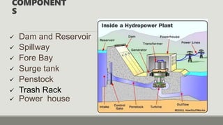
- 6. COMPONENT S Dam and Reservoir Spillway Fore Bay Surge tank Penstock Trash Rack Power house
- 7. DAM ANDRESERVOIR An open-air storage area usually formed by masonry or earthwork where water is collected and kept in quantity so that it may be drawn off for use. The water reservoir is the place behind the dam where water is stored. The water in the reservoir is located higher than the rest of the dam structure. The height of water in the reservoir decides how much potential energy the water The higher the height of water, the more its potential energy. The high position of water in the reservoir also enables it to move downwards effortlessly.
- 8. SPILLWAY Spillway is constructed to act as a safety valve. It discharge the overflow water to the down stream side when the reservoir is full. These are generally constructed of concrete and provided with water discharge opening.
- 9. FORE BAY A forebay is an artificial pool of water in front of a larger body of water. The larger body of water may be natural or human-made. Forebays have a number of functions.
- 10. SURGE TANK Surge tank acts as a temporary reservoir. It helps in stabilizing the velocity and pressure in penstock and thereby saves penstock from getting damaged. It serve as supply tank to the turbine in case of increased load conditions, and storage tank in case of low load conditions.
- 11. PENSTOCK The penstock is the long pipe or the shaft that carries the water flowing from the reservoir towards the power generation unit, comprised of the turbines and generator. Diameter = 2.4 m Length = 108 m Material used = Milestone Thickness = 12 mm Head = 62 m
- 12. TRASH RACK A trash rack or debris screen is a wooden or metal structure, frequently supported by masonry, that prevents water-borne debris from entering the intake of a water mill, pumping station or water conveyance. This protects water wheels, penstocks, and sluice gates from destruction during floods.
- 13. POWER HOUSE A power house usually contains following components: Hydraulic turbines Synchronous generators Bypass Valve MIV(Main Inlet Valve) Guide Vanes OPU(Oil Pumping Unit) GLOP(Generator Lubrication Oil Pump) Draft Tube
- 15. TURBINE(FRANCIS) Francis Turbine is a combination of both impulse and reaction turbine, where the blades rotate using both reaction and impulse force of water flowing through them producing electricity more efficiently. Francis turbine is used for the production of electricity in hydro power stations. The Francis turbine is a reaction turbine, which means that the working fluid changes pressure as it moves through the turbine, giving up its energy. The turbine is located between the high-pressure water source and the low-pressure water exit
- 17. Synchronous Generator Output :- 39176 KVA No. of Phase :- 3 4No. of Poles :- 10 Voltage(AC) :- 6600 V Current(AC) :- 343 A. Frequency :- 50 Hz Speed :- 600 per minute Coolant Temp :- 40°c Limiting Speed :- 1174 per minute Power factor :- 0.85 Stater Connection :- Star Exciting Current(DC) :- 188 A Exciting Voltage(DC) :- 267 V Altitude :- 2136 Maximum Temp. of Stator By RTD:- 90°c
- 18. MIV(Main Inlet Valve) Main inlet valve or MIV is a valve which is installed before water enters into spiral casing of the hydro turbine.. Bypass Valve It maintains the water level between MIV and shaft blades.
- 19. Guide Vanes Guide Vanes are fixed grooves found in turbines that help direct water, gas, or air around bends at maximum efficiency. As Impellers increase or decrease the flow of a substance through a system, Guide Vanes ensure that the substance is passed evenly and as smoothly as possible.
- 20. OPU(Oil Pump Unit) It used for operation of hydraulic equipment's like MIV , Bypass Valve , Braking system etc. GLOP(Generator Oil Pumping Unit) Lubricating oil pumps are used to supply oil to lubrication points, e.g. for plain bearings. In the case of circulation lubrication, the lubricating oil pump takes in an amount of oil from a reservoir, forces it through the lubrication points and then feeds it back to the reservoir. FLOW:-40lt/min
- 21. To reduce the velocity head losses of the water To allow the turbine to be set above the tailrace to facilitate inspection and maintenance DRAFT TUBE Draft Tube is an empty structure made beneath the Turbine. Rated Discharge = 4.771 cubic m/s
- 22. For Generator Breaker VCB are used. CIRCUIT BREAKER USED For Line Breaker SF6 breaker are used For transformer both(VCB and SF6) breaker are used .
- 23. CONCLUSI ON In order to achieve a growth rate of 7-8 % as envisaged in National policy of India, it is also required to tap all the small Hydro Power potential of the country. The utilization of small Hydro Power Potential is especially required in all states where the utilized potential is very low like in MP and therefore optimum utilization of the same may set up an stepping up stone for achieving self sufficiency in power sector in country.
- 24. Thanks! Do you have any questions ?