


![2
VLIW Processor Architectures
and Algorithm Mappings
for DSP Applications
Ravi A. Managuli and Yongmin Kim
University of Washington, Seattle, Washington
1 INTRODUCTION
In order to meet the real-time requirements of various applications, digital signal
processors (DSPs) have traditionally been designed with special hardware fea-
tures, such as fast multiply and accumulate units, multiple data memory banks
and support for low-overhead looping that can efficiently execute DSP algorithms
(Lee, 1988, 1989). These applications included modems, disk drives, speech
synthesis/analysis, and cellular phones. However, as many forms of media [e.g.,
film, audio, three-dimensional (3D) graphics, and video] have become digital,
new applications are emerging with the processing requirements different from
what can be provided by traditional DSPs. Several examples of new applications
include digital TV, set-top boxes, desktop video conferencing, multifunction
printers, digital cameras, machine vision, and medical imaging. These applica-
tions have large computational and data flow requirements and need to be sup-
ported in real time. In addition, these applications are quite likely to face an
environment with changing standards and requirements; thus the flexibility and
upgradability of these new products, most likely via software, will play an in-
creasingly important role.
Traditionally, if an application has a high computational requirement (e.g.,
military and medical), a dedicated system with multiple boards and/or multiple
processors was developed and used. However, for multimedia applications requir-
TM
Copyrightn2002byMarcelDekker,Inc.AllRightsReserved.](https://image.slidesharecdn.com/14358-250409033429-64f62a65/85/Programmable-digital-signal-processors-architecture-programming-and-applications-1st-Edition-Hu-5-320.jpg)


![which requires 11 cycles. On the VLIW processor that has two load/store units,
one multiply unit, and one add unit, the same code can be executed in only five
cycles.
cycle 1: load a1
load x1
cycle 2: load a2
load x2
Multiply z1 a1 x1
cycle 3: load a3
load x3
Multiply z2 a2 x2
cycle 4: multiply z3 a3 x3
add y z1 z2
cycle 5: add y y z3
Thus, the performance is approximately two times faster than that of a sequential
RISC processor. If this loop needs to be computed repeatedly (e.g., finite impulse
response [FIR]), the free slots available in cycles 3, 4, and 5 can be utilized by
overlapping the computation and loading for the next output value to improve
the performance further.
2.2 Data-Level Parallelism
Also, the programs can be sped up by performing partitioned operations where
a single arithmetic unit is divided to perform the same operation on multiple
smaller precision data, [e.g., a 64-bit arithmetic and logic unit (ALU) is parti-
tioned into eight 8-bit units to perform eight operations in parallel]. Figure 2
shows an example of partitioned_add, where eight pairs of 8-bit pixels are
added in parallel by a single instruction. This feature is often called as multimedia
extension (Lee, 1995). By dividing the ALU to perform the same operation on
Figure 2 Example partition operation: partitioned_add.
TM
Copyrightn2002byMarcelDekker,Inc.AllRightsReserved.](https://image.slidesharecdn.com/14358-250409033429-64f62a65/85/Programmable-digital-signal-processors-architecture-programming-and-applications-1st-Edition-Hu-8-320.jpg)
![multiple data, it is possible to improve the performance by two, four, or eight
times depending on the partition size. The performance improvement using data-
level parallelism is also best explained with an example of adding two arrays (a
and b, each having 128 elements, with each array element being 8 bits), which
is as follows:
/* Each element of array is 8 bits */
char a[128], b[128], c[128];
for (i ⫽ 0; i ⬍ 128; i⫹⫹){
c[i] ⫽ a[i] ⫹ b[i];
}
The same code can be executed utilizing partitioned_add:
long a[16], b[16], c[16];
for (i ⫽ 0; i ⬍ 16; i⫹⫹){
c[i] ⫽ partitioned_add(a[i], b[i]);
}
The performance with data-level parallelism is increased by a factor of 8
in this example. Because the number of loop iterations also decreases by a factor
of 8, there will be an additional performance improvement due to the reduction
of branch overhead.
2.3 Instruction Set Architecture
The data-level parallelism in multimedia applications can be utilized by a special
subset of instructions, called Single Instruction Multiple Data (SIMD) instruc-
tions (Basoglu et al., 1998; Rathnam and Slavenburg, 1998). These instructions
operate on multiple 8-, 16-, or 32-bit subwords of the operands. The current
SIMD instructions can be categorized into the following groups:
• Partitioned arithmetic/logic instructions: add, subtract, multi-
ply, compare, shift, and so forth.
• Sigma instructions: inner-product, sum of absolute difference
(SAD), sum of absolute value (SAM), and so forth
• Partitioned select instructions: min/max, conditional_selec-
tion, and so forth
• Formatting instructions: map, shuffle, compress, expand, and
so forth
• Processor-specific instructions optimized for multimedia, imaging and
3D graphics
TM
Copyrightn2002byMarcelDekker,Inc.AllRightsReserved.](https://image.slidesharecdn.com/14358-250409033429-64f62a65/85/Programmable-digital-signal-processors-architecture-programming-and-applications-1st-Edition-Hu-9-320.jpg)


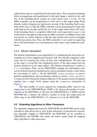
![of instructions to utilize the underlying architecture to keep all the execution
units busy is critical. For illustration, consider an example where a look-up table
operation is performed {i.e., LUT (x[i])}:
char x[128], y[128];
for (i ⫽ 0; i ⬍ 128; I⫹⫹)
y[i] ⫽ LUT(x[i]);
This algorithm mapped to the MAP1000 without considering the instruction
set architecture requires 3 IALU operation (2 loads and 1 store) per data point,
which corresponds to 384 instructions for 128 data points (assuming 1 cluster). By
utilizing multimedia instructions so that both IALU and IFGALU are well used,
the performance can be improved significantly, as shown in Figure 12. Here, four
data points are loaded in a single load IALU instruction, and the IFGALU is
utilized to separate each data point before the IALU performs LUT operations.
After performing the LUT operations, the IFGALU is again utilized to pack these
four data points so that a single store instruction can store all four results. This
algorithm leads to six IALU operations and six IFGALU operations for every four
data points. Because the IALU and IFGALU can run concurrently, this reduces the
numberofcyclesperpixelto1.5comparedto3earlier.Thisresultsinaperformance
improvement by a factor of 2. This is a simple example illustrating that it is possible
Figure 12 Performing LUT using IALU and IFGALU on the MAP1000.
TM
Copyrightn2002byMarcelDekker,Inc.AllRightsReserved.](https://image.slidesharecdn.com/14358-250409033429-64f62a65/85/Programmable-digital-signal-processors-architecture-programming-and-applications-1st-Edition-Hu-20-320.jpg)

![cycles. The result is stored after another latency of six cycles because
partitioned_multiply has a six-cycle latency. Only 3 instruction slots are
utilized out of 24 possible IALU and IFGALU slots in the inner loop, which
results in wasting 87.5% of the instruction issue slots and leads to a disappointing
computing performance.
To address this latency problem and underutilization of instruction slots,
loop unrolling and software pipelining can be utilized (Lam, 1988). In loop un-
rolling, multiple sets of data are processed inside the loop. For example, six sets
of data are processed in Figure 13b. The latency problem is partially overcome
by taking advantage of the single-cycle throughput and filling the delay slots with
the unrolled instructions. However, many instruction slots are still empty because
the IALU and IFGALU are not used simultaneously. Software pipelining can be
used to fill these empty slots, where operations from different iterations of the
loop are overlapped and executed simultaneously by the IALU and IFGALU, as
shown in Figure 13c. By the IALU loading, the data to be used in the next itera-
tion and the IFGALU executing the partitioned_multiply instructions
using the data loaded in the previous iteration, the IALU and IFGALU can exe-
cute concurrently, thus increasing the instruction slot utilization. Few free slots
available in the IFGALU unit can be utilized for controlling the loop counters.
However, to utilize software pipelining, some preprocessing and postprocessing
need to be performed, (e.g., loading in the prologue the data to be used in the
first iteration and executing partitioned_multiply and store in the epi-
logue for the data loaded in the last iteration, as shown in Figure 13c). Thus, the
judicious use of loop unrolling and software pipelining results in the increased
data processing throughput when Figures 13a and 13c are compared [a factor of
5.7 when an array of 480 is processed (i.e., 720 cycles versus 126 cycles)].
4.3 Fixed Point Versus Floating Point
The VLIW processors predominantly have fixed-point functional units with some
floating-point support. The floating-point operations are generally computation-
ally expensive with longer latency and lower throughput than fixed-point opera-
tions. Thus, it is desirable to carry out computations in fixed-point arithmetic and
avoid floating-point operations if we can.
While using fixed-point arithmetic, the programmer has to pay attention to
several issues (e.g., accuracy and overflow). When multiplying two numbers, the
number of bits required to represent the result without any loss in accuracy is
equal to the sum of the number of bits in each operand (e.g., while multiplying
two N-bit numbers 2N bits are necessary). Storing 2N bits is expensive and is
usually not necessary. If only N bits are kept, it is up to the programmer to
determine which N bits to keep. Several instructions on these VLIW processors
provide a variety of options to the programmer in selecting which N bits to keep.
TM
Copyrightn2002byMarcelDekker,Inc.AllRightsReserved.](https://image.slidesharecdn.com/14358-250409033429-64f62a65/85/Programmable-digital-signal-processors-architecture-programming-and-applications-1st-Edition-Hu-22-320.jpg)


![/* Compress eight 16-bit values to eight 8-bit values. Saturate each in-
dividual value to 0 or 255 and store them in two consecutive 32-bit regis-
ters */
result32_pu8_0 ⫽ compress2(result64_ps16_0: result64_ps16_1, zero);
result32_pu8_1 ⫽ compress2(result64_ps16_2: result64_ps16_3, zero);
/* Store 8 pixels present in two consecutive 32-bit registers and update
the destination address */
*dst_ptr⫹⫹ ⫽ result32_pu8_0_and_1;
If the kernel width is greater than 8, then the kernel can be subdivided into
several sections and the inner loop is iterated multiple times, while accumulating
the multiplication results.
The MAP1000 has an advanced inner-product instruction, called srshin-
prod.pu8.ps16, as shown in Figure 18. It can multiply eight 16-bit kernel
coefficients (of partitioned local constant [PLC] register) by eight 8-bit input
pixels (of partitioned local variable [PLV] register) and sum up the multiplication
results. This instruction can also shift a new pixel into a 128-bit PLV register.
x0 through x23 represent sequential input pixels, and c0 through c7 represent kernel
Figure 18 srshinprod.pu8.ps16 instruction using two 128-bit registers.
TM
Copyrightn2002byMarcelDekker,Inc.AllRightsReserved.](https://image.slidesharecdn.com/14358-250409033429-64f62a65/85/Programmable-digital-signal-processors-architecture-programming-and-applications-1st-Edition-Hu-31-320.jpg)
![Figure 19 Flowgraph for a 1D eight-point FFT.
coefficients. After performing an inner-product operation shown in Figure 18,
x16 is shifted into the leftmost position of the 128-bit register (PLV) and x0 is
shifted out. The next time this instruction is executed, the inner product will be
performed between x1–x8 and c0–c7. This new pixel shifting-in capability elimi-
nates the need of multiple align instructions used in the above code. An instruc-
tion called setplc.128 sets the 128-bit PLC register with kernel coefficients.
The MAP1000 also has compress instructions similar to the ones shown in
Figure 4 that can be utilized for computing the convolution output. All of the
partitioned operations can be executed only on the integer floating-point and arith-
metic graphics unit (IFGALU), whereas ALU supports load/store and branch oper-
ations as discussed in Section 3.5. Thus, for 3 ⫻ 3 convolution, the ideal number
of cycles required to process 8 output pixels are 33 [22 IALU (21 load and 1
store) instructions can be hidden behind 33 IFGALU (24 srshinprod.pu8.
ps16, 3 setplc.128, 4 compress1, 2 compress2) instructions utilizing
loop unrolling and software pipelining]. Because there are 2 clusters, the ideal
number of cycles per output pixel is 2.1.
5.2 FFT
The fast Fourier transform (FFT) has made the computation of discrete Fourier
transform (DFT) feasible, which is an essential function in a wide range of areas
that employ spectral analysis, frequency-domain processing of signals, and image
reconstruction. Figure 19 illustrates the flowgraph for a 1D 8-point FFT. Figure
20a shows the computation of butterfly and Figure 20b shows the detailed opera-
tions within a single butterfly. Every butterfly requires a total of 20 basic opera-
TM
Copyrightn2002byMarcelDekker,Inc.AllRightsReserved.](https://image.slidesharecdn.com/14358-250409033429-64f62a65/85/Programmable-digital-signal-processors-architecture-programming-and-applications-1st-Edition-Hu-32-320.jpg)

![for a butterfly in the cache or on-chip memory. Alternatively, a 2D FFT can be
decomposed by row–column 1D FFTs, which can be computed by performing
the 1D FFT on all of the rows (rowwise FFT) followed by the 1D FFT on all
of the columns (columnwise FFT) of the row FFT result as follows:
X[k, l] ⫽ 冱
N⫺1
n⫽0
冢冱
N⫺1
m⫽0
x
冢n, m
冣Wlm
N
冣Wkn
N (4)
where x is the input image, WN are the twiddle factors, and X is the FFT output.
This method requires 4N2
log2 N real multiplications and 6N2
log2 N real
additions/subtractions (Dudgeon and Mersereau, 1984), which is 33% more mul-
tiplications and 9.1% more additions/subtractions than the direct 2D approach.
However, this separable 2D FFT algorithm has been popular because all of the
data for the rowwise or columnwise 1D FFT being computed can be easily stored
in the on-chip memory or cache. The intermediate image is transposed after the
rowwise 1D FFTs so that another set of rowwise 1D FFTs can be performed.
This is to reduce the number of SDRAM row misses, which otherwise (i.e., if
1D FFTs are performed on columns of the intermediate image) will occur many
times. One more transposition is performed before storing the final result.
5.2.1 Texas Instruments TMS320C80
The dynamic range of the FFT output is ⫾2Mlog2N
, where M is the number of bits
in each input sample and N is the number of samples. Thus, if the input samples
are 8 bits, any 1D FFT with N larger than 128 could result in output values
exceeding the range provided by 16 bits. Because each ADSP has a single-cycle
16-bit multiplier, there is a need to scale the output of each butterfly stage so
that the result can be always represented in 16 bits. In Figure 20, A1 and A2 have
to be scaled explicitly before being stored, whereas the scaling of A5 and A6 can
be incorporated into M1–M4. If all of the coefficients were prescaled by one-half,
the resulting output would also be one-half of its original value. Because all of
the trigonometric coefficients are precomputed, this prescaling does not require
any extra multiplication operations.
A modified Cooley–Tukey 2-point FFT butterfly that incorporates scaling
operations is shown in Figure 21, where 22 basic operations are required. Several
observations on the flowgraph of Figure 21 lead us to efficient computation. First,
multiplications are independent from each other. Second, two (A1 and A2) of the
six additions/subtractions are independent of the multiplications M1–M4. Finally,
if the real and imaginary parts of the complex input values and coefficients are
kept adjacent and handled together during load and store operations, then the
number of load and store operations can be reduced to three and two rather than
TM
Copyrightn2002byMarcelDekker,Inc.AllRightsReserved.](https://image.slidesharecdn.com/14358-250409033429-64f62a65/85/Programmable-digital-signal-processors-architecture-programming-and-applications-1st-Edition-Hu-34-320.jpg)


![to overcome the latencies of these instructions (six for complex_multiply,
three for partitioned_add and partitioned_subtract, and five for
load and store), four butterflies can be computed in six cycles using a single
cluster. Because complex_multiply is executed on 16-bit partitioned data,
the intermediate results on the MAP1000 also require scaling operations similar
to that of the TMS320C80. However, the MAP1000 partitioned operations have
a built-in scaling feature, which eliminates the need for extra scaling operations.
Because there are two clusters, ideally it takes 0.75 cycles for a two-point butterfly.
5.3 DCT and IDCT
The discrete cosine transform has been a key component in many image and video
compression standards (e.g., JPEG, H.32X, MPEG-1, MPEG-2, and MPEG-4).
There are several approaches in speeding up the DCT/IDCT computation. Several
efficient algorithms [e.g., Chen’s IDCT (CIDCT) algorithm] (Chen et al., 1977)
have been widely used. However, on modern processors with a powerful instruc-
tion set, the matrix multiply algorithm might become faster due to their immense
computing power. In this section, an 8 ⫻ 8 IDCT is utilized to illustrate how it
can be efficiently mapped onto the VLIW processors.
The 2D 8 ⫻ 8 IDCT is given as
xij ⫽ 冱
7
k⫽0
c(k)
2 冤冱
7
l⫽0
c(l)
2
Fkl cos
冢2j ⫹ 1)lπ
16 冣冥cos
冢2i ⫹ 1)kπ
16 冣
c(k) ⫽
1
√2
for k ⫽ 0; c(k) ⫽ 1 otherwise (5)
c(l) ⫽
1
√2
for l ⫽ 0; c(l) ⫽ 1 otherwise
where F is the input data, c(⋅) are the scaling terms, and x is the IDCT result. It
can be computed in a separable fashion by using 1D eight-point IDCTs. First,
rowwise eight-point IDCTs are performed on all eight-rows, followed by col-
umnwise eight-point IDCTs on all eight columns of the row IDCT result. Instead
of performing columnwise IDCTs, the intermediate data after the computation
of rowwise IDCTs are transposed so that another set of rowwise IDCTs can be
performed. The final result is transposed once more before the results are stored.
Because the implementation of DCT is similar to that of IDCT, only the IDCT
implementation is discussed here.
5.3.1 Texas Instruments TMS320C80
Figure 22 illustrates the flowgraph for the 1D eight-point Chen’s IDCT algorithm
with the multiplication coefficients c1 through c7 given by ci ⫽ cos(iπ/16) for i ⫽
TM
Copyrightn2002byMarcelDekker,Inc.AllRightsReserved.](https://image.slidesharecdn.com/14358-250409033429-64f62a65/85/Programmable-digital-signal-processors-architecture-programming-and-applications-1st-Edition-Hu-37-320.jpg)
![Figure 22 Chen’s IDCT flowgraph.
1 through 7. When implemented with a basic instruction set, the CIDCT algorithm
requires 16 multiplications and 26 additions. Thus, including 16 loads and 8 store
operations, 66 operations are necessary. Table 3 shows the CIDCT algorithm
implemented on the TMS320C80, where operations belonging to different 1D
eight-point IDCTs (similar to FFT) are overlapped to utilize software pipelining.
Variables with a single prime and double primes (such as F′ and F″) are the
intermediate results. In Table 3, we are performing 32-bit additions/subtractions
on the intermediate data because we are allocating 32 bits for the multiplications
of two 16-bit operands to reduce quantization errors. Another description of im-
plementing CIDCT can be found in (Lee, 1997), where 16 bits are utilized for
representing multiplication results, thus performing 16-bit additions/subtractions
on the intermediate data. The coefficients need to be reloaded because of lack
of registers. Because there are 4 ADSPs, the ideal number of cycles per 8-point
IDCT in our implementation is 6.5. Thus, it takes 104 cycles to compute one
8 ⫻ 8 2D IDCT.
5.3.2 Hitachi/Equator Technologies MAP1000
Table 4 illustrates the matrix-multiply algorithm to compute one eight-point
IDCT, where each matrix element (i.e., Aux) is equal to C(u) cos[π(2x ⫹ 1)u/
16] with C(u) ⫽ 1/√2 for u ⫽ 0 and 1 otherwise. A 1D IDCT can be computed
TM
Copyrightn2002byMarcelDekker,Inc.AllRightsReserved.](https://image.slidesharecdn.com/14358-250409033429-64f62a65/85/Programmable-digital-signal-processors-architecture-programming-and-applications-1st-Edition-Hu-38-320.jpg)


![3
Multimedia Instructions
in Microprocessors for Native
Signal Processing
Ruby B. Lee and A. Murat Fiskiran
Princeton University, Princeton, New Jersey
1 INTRODUCTION
Digital signal processing (DSP) applications on computers have typically used
separate DSP chips for each task. For example, one DSP chip is used for pro-
cessing each audio channel (two chips for stereo); a separate DSP chip is used
for modem processing, and another for telephony. In systems already using a
general-purpose processor, the DSP chips represent additional hardware re-
sources. Native signal processing is DSP performed in the microprocessor itself,
with the addition of general-purpose multimedia instructions. Multimedia instruc-
tions extend native signal processing to video, graphics, and image processing,
as well as the more common audio processing needed in speech, music, modem,
and telephony applications. In this study, we describe the multimedia instructions
that have been added to current microprocessor instruction set architectures
(ISAs) for native signal processing or, more generally, for multimedia processing.
Multimedia information processing is becoming increasingly prevalent in
the general-purpose processor’s workload [1]. Workload characterization studies
on multimedia applications have revealed interesting results. More often than
not, media applications do not work on very high-precision data types. A pixel-
oriented application, for example, rarely needs to process data that are wider than
16 bits. A low-end digital audio processing program may also use only 16-bit
fixed-point numbers. Even high-end audio applications rarely require any preci-
sion beyond a 32-bit single-precision (SP) floating point (FP). Common usage
TM
Copyrightn2002byMarcelDekker,Inc.AllRightsReserved.](https://image.slidesharecdn.com/14358-250409033429-64f62a65/85/Programmable-digital-signal-processors-architecture-programming-and-applications-1st-Edition-Hu-48-320.jpg)


![This ebook is for the use of anyone anywhere in the United States and most other parts of the
world at no cost and with almost no restrictions whatsoever. You may copy it, give it away or re-use
it under the terms of the Project Gutenberg License included with this ebook or online at
www.gutenberg.org. If you are not located in the United States, you will have to check the laws of
the country where you are located before using this eBook.
Title: Excursions in North Wales
Author: John Hicklin
Release date: December 29, 2020 [eBook #64164]
Most recently updated: October 18, 2024
Language: English
Credits: Transcribed from the 1847 Whittaker and Co. edition by David Price
*** START OF THE PROJECT GUTENBERG EBOOK EXCURSIONS IN NORTH WALES ***](https://image.slidesharecdn.com/14358-250409033429-64f62a65/85/Programmable-digital-signal-processors-architecture-programming-and-applications-1st-Edition-Hu-55-320.jpg)


![railings; in the centre is the grand entrance, of Doric architecture, greatly admired for its chaste
construction and elegant execution. The front view is classical and imposing.
A noble Bridge crosses the Dee at the south-east angle of the Roodee, the picturesque Race-course of
Chester; it is approached by a new road from the centre of Bridge-street, which passes by the castle
esplanade, proceeds across the city walls, and then by an immense embankment thrown over a deep
valley. The bridge consists of one main stone arch, with a small dry arch or towing path on each side,
by which the land communication is preserved on both sides of the river. The distinguishing feature of
this edifice is the unparalleled width of the chord or span of the main arch, which is of greater extent
than that of any other arch of masonry known to have been constructed. Of its dimensions the
following is an accurate delineation:—The span of the arch is two hundred feet; [0]
the height of the arch
from the springing line, 40 feet; the dimensions of the main abutments, 48 feet wide by 40, with a dry
arch as a towing path at each side, 20 feet wide, flanked with immense wing walls, to support the
embankment. The whole length of the road-way, 340 feet. Width of the bridge from outside the
parapet walls, 35 feet 6 inches, divided thus: carriage-road, 24 feet; the two causeways, 9 feet;
thickness of the parapet walls, 2 feet 6 inches. Altitude from the top of the parapet wall to the river at
low water mark, 66 feet 6 inches. The architectural plan of this bridge was furnished by the late Mr.
Thomas Harrison; Mr. James Trubshaw, of Newcastle, Staffordshire, was the builder; Mr. Jesse Hartley,
of Liverpool, the surveyor. The bridge was formally opened in October, 1832, by her Royal Highness the
Princess (now Queen) Victoria, on occasion of her visit and that of her royal parent, the Duchess of
Kent, to Eaton Hall. As a compliment to her noble host, the bridge was named Grosvenor Bridge by the
young Princess.
Our limited space prevents us from entering into particular descriptions of other buildings and
antiquities, which might well claim our attention; as the remarkable Crypt and Roman Bath in Bridge-
street, the Museum at the Water Tower, the Blue Goat Hospital, the Training College, the Linen Hall, the
Episcopal Palace, the Exchange, &c.; but we must not omit to remind the stranger, that when at
Chester, he is only three miles distant from that magnificent modern mansion, Eaton Hall, the seat of
the Marquis of Westminster. The approach to the beautiful and extensive park in which this princely
abode is situated, is by an elegant Lodge on the Grosvenor Road, about a quarter of a mile from
Chester Castle; or the excursion may be made by a boat on the lucid bosom of the river Dee, which
runs through verdant meads and lovely scenery close by the pleasure-grounds of the Hall. Visitors must
be careful to provide themselves with tickets, which may be obtained of the publisher of this little work
in Bridge-street Row, or they will not be admitted to view the interior of the mansion. The elaborate
adornments, the gorgeous fittings, and the truly magnificent architecture of Eaton Hall, with its superb
furniture, its beautiful pictures, and exquisite sculpture, never fail to excite the most lively admiration;
and to pass it without a call, would be held by the residents of this neighbourhood to be a sort of
topographical heresy, of which tourists should not be guilty.
Having satisfied their taste and curiosity by exploring the attractions and characteristics of Chester and
the vicinity, we will suppose that our travellers are now ready to proceed into Wales; and for the
purpose of directing and enlivening their journey, we present them, in this little Manual, with a faithful
Guide and an amusing Companion by the way. The admirer of Nature, in her wildest or her loveliest
guise; the man of antiquarian research, the student of history, the valetudinarian in quest of health, or
the ardent votary of “the rod and line,” anxiously seeking for favourable spots where the angler may
best indulge his piscatorial fancies; may find in the following pages some information adapted to his
taste and pursuits.
Among the other advantages which Chester possesses as a starting-place for visiting the Principality,
may be mentioned its position as a grand central terminus, where the London and North Western, the
Chester and Holyhead, the Shrewsbury and Chester, the Chester and Birkenhead, and the Lancashire
and Cheshire Junction Railways, meet. A splendid station, commensurate with the requirements of the
traffic from this combination of railway interests, will forthwith be built at Chester, at an estimated cost
of £80,000. The Shrewsbury and Chester line being now open as far as Ruabon, pleasant excursions
can easily be made to the vale of Gresford, Wrexham, Wynnstay Park, and Llangollen: and as in August](https://image.slidesharecdn.com/14358-250409033429-64f62a65/85/Programmable-digital-signal-processors-architecture-programming-and-applications-1st-Edition-Hu-59-320.jpg)


![ABERFFRAW,
(Anglesea.)
Caernarvon Ferry 3
Mona Inn 8
Newborough 7
Aberffraw, once a princely residence, is now reduced to a few small houses; it is situated on the river
Ffraw, near a small bay. Not a vestige is to be seen of its former importance, except the rude wall of an
old barn, and Gardd y Llys, at the west end of the town. It was a chief seat of the native princes, and
one of the three courts of justice for the Principality. Here was always kept one of the three copies of
the ancient code of laws. This place is of great antiquity, being one of three selected by Roderic the
Great, about 870, for the residence of his successors. In 962 it was ravaged by the Irish. An extent
was made of Aberffraw in the 13th Edward III, from which may be learned some of the ancient
revenues of the Welsh princes. It appeared that part arose from the rents of lands, from the profits of
mills and fisheries, and often from things taken in kind; but the last more frequently commuted for their
value in money. There is a good inn called the Prince Llywelyn.
Near to Aberffraw is Bodorgan, the seat of Owen Augustus Fuller Meyrick, Esq., which is pleasantly
situated, and overlooks Caernarvon bay. The mansion, gardens, and conservatories are worth a visit
from the tourist
ABERGELE,
(Denbighshire.)
Bangor 27
Chester 35
Conway 12
London 225
Rhuddlan 5
Rhyl 7
St. Asaph 8
Abergele, [8]
a market town, is pleasantly situated on the great Chester and Holyhead road, on the edge
of Rhuddlan marsh, and about a mile from the sea shore. The church is ancient, with a plain
uninteresting tower, which the white-washing hand of modern “improvement” has deprived of all
pretensions to the picturesque. The town consists only of one long street; and in 1841, its population,
with the parish, was returned at 2661.
The coast is composed of firm hard sands, affording delightful drives for many miles. Tradition says, the
sea has in old time overflowed a vast tract of inhabited country, once extending at least three miles
northward; as an evidence of which, a dateless epitaph, in Welsh, on the church-yard wall, is cited,
which is thus translated: “In this church yard lies a man who lived three miles to the north of it.” There
is, however, much stronger proof in the fact, that at low water may be seen, at a distance from the
clayey bank, a long tract of hard loam, in which are imbedded numerous bodies of oak trees, tolerably
entire, but so soft as to cut with a knife as easily as wax: the wood is collected by the poorer people,
and, after being brought to dry upon the beach, is used as fuel.](https://image.slidesharecdn.com/14358-250409033429-64f62a65/85/Programmable-digital-signal-processors-architecture-programming-and-applications-1st-Edition-Hu-70-320.jpg)
![The salubrity of the air, the pleasantness of situation, and the superiority of its shore for sea-bathing,
have rendered this town a favourite resort for genteel company, and it has long been a fashionable
watering place. The environs are picturesque, the scenery beautiful, and many interesting excursions
may be made from this locality. The Bee Hotel, one of the best in the kingdom, is a most comfortable
house, and possesses superior accommodations; and there are some excellent private lodgings to be
had in the town: for those who would prefer a more immediate contiguity to the sea, there are cottages
close to the beach, fit for respectable families, and apartments may be had from farmers, who are in
the habit of accommodating visitors for the summer season. Bateman Jones, Esq. has a handsome
residence on the road between the town and the beach. Besides the Chester and Holyhead and other
mails that pass through Abergele, there is an omnibus which runs daily to Voryd, to meet the Liverpool
and Rhyl steam-packet.
The pretty villages of Bettws and Llanfair are in this immediate neighbourhood: near the former is Coed
Coch, the residence of J. Ll. Wynn, Esq. Llanfair is most picturesquely situated on the Elwy, a little way
above its conflux with the Aled. Close to the village is Garthewin, the sylvan residence of Brownlow W.
Wynne, Esq. embowered in trees; and following up the Elwy and its narrow but beautiful valley, is the
village of Llangerniew; near to it is Llyn Elwy, the pool from which issues and gives name to the river
Elwy. Havod-unos, about a quarter of a mile from the village, is the seat of S. Sandbach, Esq. an
eminent Liverpool merchant, who some time ago purchased it and the estate, once the property of a
long list of ap Llwyds. Two or three miles to the south-east, lies the village of Llansannan, at the head
of the pretty vale of Aled. Close below the village is the elegant modern mansion of the Yorkes, called
Dyffryn Aled: it is built of Bath free stone, and presents a very beautiful and classical structure. These
are places a little out of the common track of tourists, but they will not be disappointed at visiting them;
and from Abergele is the most convenient start to them. The roads are good; the country very
beautiful; trout fishing is excellent in the Elwy and Aled from their sources, the Aled and Elwy pools, to
Rhuddlan; and the villages afford very good passing-by accommodations.
On the hills above Abergele, grow some of the more uncommon plants; geranium sanguineum, rubia
peregrina, halloboris fœtidus. In the shady wood, paris quadrifolia, and ophrys nidus avis; and on the
beach, glaucium luteum, and eryngium maritimum abundantly. The hills are interesting to the geologist
as well as to the botanist; and command remarkably grand and extensive views of the ocean, and of
the adjacent mountain scenery.
About a mile from Abergele, on the left of the road towards Conway, stands Gwrych Castle, a modern
castellated mansion, the property and residence of Henry Lloyd Bamford Hesketh, Esq. The situation is
admirably chosen for a magnificent sea view, which, owing to the constant passing of vessels for the
ports of Liverpool and Chester, is extremely beautiful and animated. Very near to this singular but
ambitious looking structure, is a huge calcareous rock, called Cefn-yr-Ogo (or the Back of the Cavern),
an inexhaustible mine of limestone, where a multitude of labourers are constantly employed in blasting
the rock, and breaking the masses, which are exported to Liverpool and other places. But what chiefly
renders it curious is the circumstance of a number of natural caverns penetrating its side in different
places; one of which, called Ogo (or the Cavern), is well worth a visit. It is celebrated in history as
having once afforded a place of retreat to a British army. Its mouth resembles the huge arched
entrance of a Gothic cathedral. A few feet within this, and immediately in the centre of it, a rock rising
from the floor to the lofty roof, not unlike a massive pillar rudely sculptured, divides the cavern into two
apartments. The hollow to the left soon terminates; but that to the right spreads into a large chamber,
30 feet in height, and stretching to a greater depth than human curiosity has ever been hardy enough
to explore. Making a short turn a few yards from the entrance, and sweeping into the interior of the
mountain, the form and dimension of the abyss are concealed in impenetrable darkness, and its
windings can only be followed about forty yards with prudence, when the light totally disappears, and
the flooring becomes both dirty and unsafe. Stalactites of various fanciful forms decorate the fretted
roof and sides of this extraordinary cavern. [10]
From Cave Hill (Cefn-yr-Ogo), is an extensive and varied prospect. The city of St. Asaph, the Vale of
Clwyd, the mountains of Flintshire, and in clear weather, a portion of Cheshire and Lancashire, with the](https://image.slidesharecdn.com/14358-250409033429-64f62a65/85/Programmable-digital-signal-processors-architecture-programming-and-applications-1st-Edition-Hu-71-320.jpg)
![town of Liverpool, are distinctly seen to the eastward; and to the north is visible the Isle of Man; to the
west, the Island of Anglesea; and to the south-west, the mountains of Caernarvonshire. Just below is
the small village of
Llanddulas.
In this little village or glen it is supposed that Richard the Second was surrounded and taken by a band
of ruffians, secreted by the Earl of Northumberland, for the purpose of forcing him into the hands of
Bolingbroke, who was at Flint. Here enterprise has discovered the means of realizing wealth. A railway,
several miles long, has been constructed from the sea to Llysfaen limestone rocks, being on a
remarkably steep incline down the side of the mountain. It is a stupendous work, and highly creditable
to the projector, Mr. Jones.
About two miles nearer Conway, is the increasing and respectable village of Colwyn. A new church has
lately been erected here. Glan-y-don, the seat of H. Hesketh, Esq., is in this neighbourhood; Mr. Wynne
and Dr. Cumming have cottages here, and many other genteel residences have recently been built. The
sea bathing is very good, and the place is pleasant and salubrious. Up the valley, to the left of the
bridge, is the village of Llanelian, with its calm green meadows, and its far-famed holywell, or Ffynan
Fair.
Returning to Abergele, and at the opposite end, is a good and direct road to Rhuddlan, through a
number of excellent and extensive corn farms. The road crosses the celebrated Morva Rhuddlan (or
Rhuddlan Marsh).
About three miles on the St. Asaph road is the neat and clean little village of
St. George, or Llan Saint Sior; [12]
And about a quarter of a mile before you come to it, you pass on your right Pen-y-Parc Hill, on the top
of which is a Roman encampment, afterwards occupied by the famous Owen Gwynedd, during his
struggles against English encroachments; and it was here he pitched his tents after his “fine retreat
before Henry the Second, whom he here kept at bay.” The curious may visit it from the village,
inquiring for Park Meirch, where the old battles were fought. And close to this place is Dinorben, an
ancient manor-house, from which is the title of Lord Dinorben, whose residence, Kinmel Park, is a little
beyond, and close to the village. About six years since the mansion was destroyed by fire; but has now
been rebuilt in a style of princely elegance, and has once more become the home of that hospitality for
which the respected proprietor is famous. The park is finely wooded and well stocked with deer. The
scenery from the house is rich, varied, and beautiful; the gardens and grounds are extensive, and
tastefully laid out. His royal highness, the Duke of Sussex, for several years before his death, annually
spent some weeks at Kinmel in the shooting season.
The church at St. George is a neat structure, and has recently been restored by Lord Dinorben, the
patron. In the church-yard is a costly stone mausoleum, in the Gothic style, erected over the remains of
Lady Dinorben, a lady beloved for her virtues, and eminent for her charities. The architect was Mr.
Jones, of Chester: the design and workmanship are chaste and elegant.
Not far from Kinmel, towards St. Asaph, is Bodelwyddan, the modern elegant mansion of Sir John Hay
Williams, Bart., one of the most lovely spots in Wales; and in the plain below is Pengwern, the
hospitable seat of Lord Mostyn.
ABERYSTWYTH,
(Cardiganshire.)
Aberdovey 11
Devil’s Bridge 12](https://image.slidesharecdn.com/14358-250409033429-64f62a65/85/Programmable-digital-signal-processors-architecture-programming-and-applications-1st-Edition-Hu-72-320.jpg)


More Related Content
Similar to Programmable digital signal processors architecture programming and applications 1st Edition Hu (20)
Recently uploaded (20)


Programmable digital signal processors architecture programming and applications 1st Edition Hu
- 1. Programmable digital signal processors architecture programming and applications 1st Edition Hu pdf download https://ebookgate.com/product/programmable-digital-signal- processors-architecture-programming-and-applications-1st-edition- hu/ Get Instant Ebook Downloads – Browse at https://ebookgate.com
- 2. Instant digital products (PDF, ePub, MOBI) available Download now and explore formats that suit you... Mitsubishi FX Programmable Logic Controllers Applications and Programming 2nd Edition John Ridley Dipee Ceng Miee Cert Ed https://ebookgate.com/product/mitsubishi-fx-programmable-logic- controllers-applications-and-programming-2nd-edition-john-ridley- dipee-ceng-miee-cert-ed/ ebookgate.com Multirate filtering for digital signal processing MATLAB applications 1st Edition Ljiljana Milic https://ebookgate.com/product/multirate-filtering-for-digital-signal- processing-matlab-applications-1st-edition-ljiljana-milic/ ebookgate.com Real Time Digital Signal Processing 2nd Edition Implementations and Applications Sen M. Kuo https://ebookgate.com/product/real-time-digital-signal-processing-2nd- edition-implementations-and-applications-sen-m-kuo/ ebookgate.com Digital Signal Processing 1st Edition J.S. Chitode https://ebookgate.com/product/digital-signal-processing-1st-edition-j- s-chitode/ ebookgate.com
- 3. Microprocessor Architecture Programming and Applications with the 8085 5th ed Edition Ramesh S. Gaonkar https://ebookgate.com/product/microprocessor-architecture-programming- and-applications-with-the-8085-5th-ed-edition-ramesh-s-gaonkar/ ebookgate.com Digital Signal and Image Processing 1st Edition Tamal Bose https://ebookgate.com/product/digital-signal-and-image-processing-1st- edition-tamal-bose/ ebookgate.com Information Fusion in Signal and Image Processing Digital Signal and Image Processing 1st Edition Isabelle Bloch https://ebookgate.com/product/information-fusion-in-signal-and-image- processing-digital-signal-and-image-processing-1st-edition-isabelle- bloch/ ebookgate.com Modern Digital Signal Processing 1st Edition Roberto Cristi https://ebookgate.com/product/modern-digital-signal-processing-1st- edition-roberto-cristi/ ebookgate.com Digital Signal Processing fundamentals and application 1st Edition Li Tan https://ebookgate.com/product/digital-signal-processing-fundamentals- and-application-1st-edition-li-tan/ ebookgate.com
- 5. 2 VLIW Processor Architectures and Algorithm Mappings for DSP Applications Ravi A. Managuli and Yongmin Kim University of Washington, Seattle, Washington 1 INTRODUCTION In order to meet the real-time requirements of various applications, digital signal processors (DSPs) have traditionally been designed with special hardware fea- tures, such as fast multiply and accumulate units, multiple data memory banks and support for low-overhead looping that can efficiently execute DSP algorithms (Lee, 1988, 1989). These applications included modems, disk drives, speech synthesis/analysis, and cellular phones. However, as many forms of media [e.g., film, audio, three-dimensional (3D) graphics, and video] have become digital, new applications are emerging with the processing requirements different from what can be provided by traditional DSPs. Several examples of new applications include digital TV, set-top boxes, desktop video conferencing, multifunction printers, digital cameras, machine vision, and medical imaging. These applica- tions have large computational and data flow requirements and need to be sup- ported in real time. In addition, these applications are quite likely to face an environment with changing standards and requirements; thus the flexibility and upgradability of these new products, most likely via software, will play an in- creasingly important role. Traditionally, if an application has a high computational requirement (e.g., military and medical), a dedicated system with multiple boards and/or multiple processors was developed and used. However, for multimedia applications requir- TM Copyrightn2002byMarcelDekker,Inc.AllRightsReserved.
- 6. ing high computational power at a low cost, these expensive multiprocessor systems are not usable. Thus, to meet this growing computational demand at an affordable cost, new advanced processor architectures with a high level of on-chip parallelism have been emerging. The on-chip parallelism is being implemented mainly using both instruction-level and data-level parallelism. Instruction-level parallelism allows multiple operations to be initiated in a single clock cycle. Two basic approaches to achieving a high degree of instruction-level parallelism are VLIW (Very Long Instruction Word) and superscalar architec- tures (Patterson and Hennessy, 1996). Philips Trimedia TM1000, Fujitsu FR500, Texas Instruments TMS320C62 and TMS320C80, Hitachi/Equator Technologies MAP1000, IBM/Motorola PowerPC 604, Intel Pentium III, SGI (Silicon Graph- ics Inc.) R12000, and Sun Microsystems UltraSPARC III are few examples of recently developed VLIW/superscalar processors. With data-level parallelism, a single execution unit is partitioned into multiple smaller data units. The same operation is performed on multiple datasets simultaneously. Sun Microsystems’ VIS (Visual Instruction Set), Intel’s MMX, HP’s MAX-2 (Multimedia Accelera- tion eXtensions-2), DEC’s MAX (MultimediA eXtensions), and SGI’s MIPS MDMX (MIPS Digital Media eXtension) are several examples of data-level par- allelism. Several factors make the VLIW architecture especially suitable for DSP applications. First, most DSP algorithms are dominated by data-parallel computa- tion and consist of core tight loops (e.g., convolution and fast Fourier transform) that are executed repeatedly. Because the program flow is deterministic, it is possible to develop and map a new algorithm efficiently to utilize the on- chip parallelism to its maximum prior to the run time. Second, single-chip high- performance VLIW processors with multiple functional units (e.g., add, multiply and load/store) have become commercially available recently. In this chapter, both architectural and programming features of VLIW pro- cessors are discussed. In Section 2, VLIW’s architectural features are outlined, and several commercially-available VLIW processors are discussed in Section 3. Algorithm mapping methodologies on VLIW processors and the implementation details for several algorithms are presented in Sections 4 and 5, respectively. 2 VLIW ARCHITECTURE A VLIW processor has a parallel internal architecture and is characterized by having multiple independent functional units (Fisher, 1984). It can achieve a high level of performance by utilizing instruction-level and data-level parallelisms. Figure 1 illustrates the block diagram for a typical VLIW processor with N func- tional units. TM Copyrightn2002byMarcelDekker,Inc.AllRightsReserved.
- 7. Figure 1 Block diagram for a typical VLIW processor with multiple functional units (FUs). 2.1 Instruction-Level Parallelism The programs can be sped up by executing several RISC-like operations, such as load, stores, multiplications and additions, all in parallel on different functional units. Each very long instruction contains an operation code for each functional unit, and all the functional units receive their operation codes at the same time. Thus, VLIW processors typically follow the same control flow across all func- tional units. The register file and on-chip memory banks are shared by multiple functional units. A better illustration of instruction-level parallelism (ILP) is pro- vided with an example. Consider the computation of y ⫽ a1 x1 ⫹ a2 x2 ⫹ a3 x3 on a sequential RISC processor cycle 1: load a1 cycle 2: load x1 cycle 3: load a2 cycle 4: load x2 cycle 5: multiply z1 a1 x1 cycle 6: multiply z2 a2 x2 cycle 7: add y z1 z2 cycle 8: load a3 cycle 9: load x3 cycle 10: multiply z1 a3 x3 cycle 11: add y y z2 TM Copyrightn2002byMarcelDekker,Inc.AllRightsReserved.
- 8. which requires 11 cycles. On the VLIW processor that has two load/store units, one multiply unit, and one add unit, the same code can be executed in only five cycles. cycle 1: load a1 load x1 cycle 2: load a2 load x2 Multiply z1 a1 x1 cycle 3: load a3 load x3 Multiply z2 a2 x2 cycle 4: multiply z3 a3 x3 add y z1 z2 cycle 5: add y y z3 Thus, the performance is approximately two times faster than that of a sequential RISC processor. If this loop needs to be computed repeatedly (e.g., finite impulse response [FIR]), the free slots available in cycles 3, 4, and 5 can be utilized by overlapping the computation and loading for the next output value to improve the performance further. 2.2 Data-Level Parallelism Also, the programs can be sped up by performing partitioned operations where a single arithmetic unit is divided to perform the same operation on multiple smaller precision data, [e.g., a 64-bit arithmetic and logic unit (ALU) is parti- tioned into eight 8-bit units to perform eight operations in parallel]. Figure 2 shows an example of partitioned_add, where eight pairs of 8-bit pixels are added in parallel by a single instruction. This feature is often called as multimedia extension (Lee, 1995). By dividing the ALU to perform the same operation on Figure 2 Example partition operation: partitioned_add. TM Copyrightn2002byMarcelDekker,Inc.AllRightsReserved.
- 9. multiple data, it is possible to improve the performance by two, four, or eight times depending on the partition size. The performance improvement using data- level parallelism is also best explained with an example of adding two arrays (a and b, each having 128 elements, with each array element being 8 bits), which is as follows: /* Each element of array is 8 bits */ char a[128], b[128], c[128]; for (i ⫽ 0; i ⬍ 128; i⫹⫹){ c[i] ⫽ a[i] ⫹ b[i]; } The same code can be executed utilizing partitioned_add: long a[16], b[16], c[16]; for (i ⫽ 0; i ⬍ 16; i⫹⫹){ c[i] ⫽ partitioned_add(a[i], b[i]); } The performance with data-level parallelism is increased by a factor of 8 in this example. Because the number of loop iterations also decreases by a factor of 8, there will be an additional performance improvement due to the reduction of branch overhead. 2.3 Instruction Set Architecture The data-level parallelism in multimedia applications can be utilized by a special subset of instructions, called Single Instruction Multiple Data (SIMD) instruc- tions (Basoglu et al., 1998; Rathnam and Slavenburg, 1998). These instructions operate on multiple 8-, 16-, or 32-bit subwords of the operands. The current SIMD instructions can be categorized into the following groups: • Partitioned arithmetic/logic instructions: add, subtract, multi- ply, compare, shift, and so forth. • Sigma instructions: inner-product, sum of absolute difference (SAD), sum of absolute value (SAM), and so forth • Partitioned select instructions: min/max, conditional_selec- tion, and so forth • Formatting instructions: map, shuffle, compress, expand, and so forth • Processor-specific instructions optimized for multimedia, imaging and 3D graphics TM Copyrightn2002byMarcelDekker,Inc.AllRightsReserved.
- 10. The instructions in the first category perform multiple arithmetic opera- tions in one instruction. The example of partitioned_add is shown in Figure 2, which performs the same operation on eight pairs of pixels simultaneously. These partitioned arithmetic/logic units can also saturate the result to the maximum positive or negative value, truncate the data, or round the data. The instructions in the second category are very powerful and useful in many DSP algorithms. Equation (1) is an inner-product example, whereas Eq. (2) de- scribes the operations performed by the SAD instruction, where x and c are eight 8-bit data stored in each 64-bit source operand and the results are accumulated in y: y ⫽ 冱 i⫽7 i⫽0 ci xi (1) y ⫽ 冱 i⫽7 i⫽0 |ci ⫺ xi | (2) The inner-product instruction is ideal in implementing convolution- type algorithms, and the SAD and SAM instructions are very useful in video pro- cessing (e.g., motion estimation). The third category of instructions can be used in minimizing the occurrence of if/then/else to improve the utilization of instruction-level parallelism. The formatting instructions in the fourth category are mainly used for rearranging the data in order to expose and exploit the data- level parallelism. An example of using shuffle and combine to transpose a 4 ⫻ 4 block is shown in Figure 3. Two types of compress are presented in Figure 4. compress1 in Figure 4a packs two 32-bit values into two 16-bit values and stores them into a partitioned 32-bit register while performing the right-shift operation by a specified amount. compress2 in Figure 4b packs four 16-bit values into four 8-bit values while performing the right-shift operation by a specified amount. compress2 saturates the individual partitioned results after compressing to 0 or 255. In the fifth category of instructions, each processor has Figure 3 Transpose of a 4 ⫻ 4 block using shuffle and combine. TM Copyrightn2002byMarcelDekker,Inc.AllRightsReserved.
- 11. Figure 4 Partitioned 64-bit compress instructions. its own instructions to further enhance the performance. For example, complex_multiply shown in Figure 5, which performs two partitioned com- plex multiplications in one instruction, is useful for implementing the FFT and autocorrelation algorithms. Although these instructions are powerful, they take multiple cycles to com- plete, which is defined as latency. For example, partitioned arithmetic/logic in- structions have a three-cycle latency, whereas sigma instructions have a latency of five to six cycles. To achieve the best performance, all the execution units need to be kept as busy as possible in every cycle, which is difficult due to these latencies. However, these instructions have a single-cycle throughput (i.e., another identical operation can be issued in the next cycle) due to hardware pipe- lining. In Section 4.2, loop unrolling and software pipelining are discussed, which tries to exploit this single-cycle throughput to overcome the latency problem. Many improvements in the processor architectures and powerful instruction sets have been steadily reducing the processing time, which makes the task of bringing the data from off-chip to on-chip memory fast enough so as not to slow Figure 5 complex-multiply instruction. TM Copyrightn2002byMarcelDekker,Inc.AllRightsReserved.
- 12. down the functional units a real challenge. This problem gets exasperated with the growing speed disparity between the processor and the off-chip memory (e.g., the number of CPU cycles required to access the main memory doubles approxi- mately every 6.2 years) (Boland and Dollas, 1994). 2.4 Memory I/O There are several methods to move the data between slower off-chip memory and faster on-chip memory. The conventional method of handling data transfers in general-purpose processors has been via data caches (Basoglu et al., 1998), whereas the DSPs have been relying more on direct memory access (DMA) controllers (Berkeley Design Technology, 1996). Data caches have a nonpredictable access time. The data access time to handle a cache miss is at least an order of magnitude slower than that of a cache hit. On the other hand, the DMA controller has a predictable access time and can be programmed to hide the data transfer time be- hind the processing time by making it work independently of the core processor. The real-time requirement of many DSP applications is one reason that the DSP architecture traditionally contains a DMA controller rather than data caches. The DMA can provide much higher performance with predictability. On the other hand, it requires some effort by the programmer; for example, the data transfer type, amount, location, and other information, including synchronization between DMA and processor, have to be thought through and specified by the programmer (Kim et al., 2000). In Section 4.6, DMA programming techniques to hide the data movement time behind the core processor’s computing time are presented. Many DSP programmers have developed their applications in assembly language. However, programming in assembly language is difficult to code, de- bug, maintain, and port, especially as applications become larger and more com- plex and processor architectures get very sophisticated. For example, the arrival of powerful VLIW processors with the complex instruction set and the need to perform loop unrolling and software pipelining has increased the complexity and difficulty of assembly language programming significantly. Thus, much effort is being made to develop intelligent compilers that can reduce or ultimately elimi- nate the burden and need of assembly language programming. In Section 3, several commercially available VLIW processors are briefly reviewed. In Sections 4 and 5, how to program VLIW processors will be dis- cussed in detail. 3 EXAMPLES OF VLIW PROCESSORS Every VLIW processor tries to utilize both instruction-level and data-level paral- lelisms. They distinguish themselves in the number of banks and amount of on- TM Copyrightn2002byMarcelDekker,Inc.AllRightsReserved.
- 13. chip memory and/or cache, the number and type of functional units, the way in which the global control flow is maintained, and the type of interconnections between the functional units. In this section, five VLIW processors and their basic architectural features are briefly discussed. Many of these processors have additional functional units to perform sequential processing, such as that required in MPEG’s Huffman decoding. 3.1 Texas Instruments TMS320C62 The Texas Instruments TMS320C62 (Texas Instruments, 1999) shown in Figure 6 is a VLIW architecture with 256 bits per instruction. This DSP features two clusters, each with four functional units. Each cluster has its own 16, 32-bit regis- ters with 2 read ports and 1 write port for each functional unit. There is one cross-cluster read port each way, so a functional unit in one cluster can access values stored in the register file of the other cluster. Most operations have a single-cycle throughput and a single-cycle latency except for a few operations. For example, a multiply operation has a single-cycle throughput and a two-cycle latency, whereas a load/store operation has a single-cycle throughput and a five- cycle latency. Two integer arithmetic units support partitioned operations, in that each 32-bit arithmetic and logic unit (ALU) can be split to perform two 16-bit additions or two 16-bit subtractions. The TMS320C62 also features a programma- ble DMA controller combined with two 32-kbyte on-chip data memory blocks to handle I/O data transfers. Figure 6 Block diagram of the Texas Instruments TMS320C62. TM Copyrightn2002byMarcelDekker,Inc.AllRightsReserved.
- 14. 3.2 Fujitsu FR500 The block diagram of the Fujitsu FR500 (Fujitsu Limited, 1999) VLIW processor is shown in Figure 7. It can issue up to four instructions per cycle. It has two integer units, two floating-point units, a 16-kbyte four-way set-associative data cache, and a 16-kbyte four-way set-associative instruction cache. This processor has 64 32-bit general purpose registers and 64 32-bit floating-point registers. Integer units are responsible for double-word load/store, branch, integer multiply, and integer divide operations. They also support integer operations, such as rotate, shift, and AND/OR. All of these integer operations have a single-cycle latency except load/store, multiply, and divide. Multiply has a 2-cycle latency with a single-cycle throughput, divide has a 19-cycle latency with a 19-cycle throughput, and load/store has a 3-cycle latency with a single-cycle throughput. Floating- point units are responsible for single-precision floating-point operations, double- word load and SIMD-type operations. All of the floating-point operations have a three-cycle latency with a single-cycle throughput except load, divide, and square root. Floating-point divide and square root operations have a 10-cycle and 15-cycle latency, respectively, and they cannot be pipelined with another floating- point divide or square root operation because the throughput for both of these operations is equal to their latency. For load, latency is four-cycle, whereas throughput is single cycle. The floating-point unit also performs multiply and accumulate with 40-bit accumulation, partitioned arithmetic operations on 16-bit data, and various formatting operations. Partitioned arithmetic operations have either one- or two-cycle latency with a single-cycle throughput. All computing units support predicated execution for if/then/else-type statements. Be- Figure 7 Block diagram of the Fujitsu FR500. TM Copyrightn2002byMarcelDekker,Inc.AllRightsReserved.
- 15. cause this processor does not have a DMA controller, it has to rely on a caching mechanism to move the data between on-chip and off-chip memory. 3.3 Texas Instruments TMS320C80 The Texas Instruments TMS320C80 (Guttag et al., 1992) incorporates not only instruction-level and data-level parallelisms but also multiple processors on a single chip. Figure 8 shows the TMS320C80’s block diagram. It contains four Advanced Digital Signal Processors (ADSPs; each ADSP is a DSP with a VLIW architecture), a reduced instruction set computer (RISC) processor, and a pro- grammable DMA controller called a transfer controller (TC). Each ADSP has its own 2-kbyte instruction cache and four 2-kbyte on-chip data memory modules that are serviced by the DMA controller. The RISC processor has a 4-kbyte in- struction cache and a 4-kbyte data cache. Each ADSP has a 16-bit multiplier, a three-input 32-bit ALU, a branch unit, and two load/store units. The RISC processor has a floating-point unit, which can issue floating-point multiply/accumulate instructions on every cycle. The pro- grammable DMA controller supports various types of data transfers with complex address calculations. Each of the five processors is capable of executing multiple operations per cycle. Each ADSP can execute one 16-bit multiplication (which can be partitioned into two 8-bit multiply units), one 32-bit add/subtract (that can be partitioned into two 16-bit or four 8-bit units), one branch, and two load/ Figure 8 Block diagram of the Texas Instruments TMS320C80. TM Copyrightn2002byMarcelDekker,Inc.AllRightsReserved.
- 16. store operations in the same cycle. Each ADSP also has three zero-overhead loop controllers. However, this processor does not support some powerful operations, such as SAD or inner-product. All operations on the ADSP including load/ store, multiplication and addition are performed in a single cycle. 3.4 Philips Trimedia TM1000 The block diagram of the Philips Trimedia TM1000 (Rathnam and Slavenburg, 1998) is shown in Figure 9. It has a 16-kbyte data cache, a 32-kbyte instruction cache, 27 functional units, and coprocessors to help the TM-1000 perform real- time MPEG-2 decoding. In addition, TM1000 has one peripheral component in- terface (PCI) port and various multimedia input/output ports. The TM1000 does not have a programmable DMA controller and relies on the caching mechanism to move the data between on-chip and off-chip memory. The TM1000 can issue 5 simultaneous operations to 5 out of the 27 functional units per cycle (i.e., 5 operation slots per cycle). The two DSP-arithmetic logic units (DSPALUs) can each perform either 32-bit or 8-bit/16-bit partitioned arithmetic operations. Each of the two DSP-multiplier (DSPMUL) units can issue two 16 ⫻ 16 or four 8 ⫻ 8 multiplications per cycle. Furthermore, each DSPMUL can perform an inner- product operation by summing the results of its two 16 ⫻ 16 or four 8 ⫻ 8 multiplications. In ALU, pack/merge (for data formatting) and select operations Figure 9 Block diagram of the Philips Trimedia TM1000. TM Copyrightn2002byMarcelDekker,Inc.AllRightsReserved.
- 17. are provided for 8-bit or 16-bit data in the 32-bit source data. All of the partitioned operations, including load/store and inner-product type operations, have a three- cycle latency and a single-cycle throughput. 3.5 Hitachi/Equator Technologies MAP1000 The block diagram of the Hitachi/Equator Technologies MAP1000 (Basoglu et al., 1999) is shown in Figure 10. The processing core consists of two clusters, a 16-kbyte four-way set-associative data cache, a 16-kbyte two-way set-associative instruction cache, and a video graphics coprocessor for MPEG-2 decoding. It has an on-chip programmable DMA controller called Data Streamer (DS). In addi- tion, the MAP1000 has two PCI ports and various multimedia input/output ports, as shown in Figure 10. Each cluster has 64, 32-bit general registers, 16 predicate registers, a pair of 128-bit registers, an Integer Arithmetic and Logic Unit (IALU), and an Integer Floating-Point Graphics Arithmetic Logic Unit (IFGALU). Two clusters are capable of executing four different operations (e.g., two on IALUs and two on IFGALUs) per clock cycle. The IALU can perform either a 32-bit fixed-point arithmetic operation or a 64-bit load/store operation. The IFGALU can perform 64-bit partitioned arithmetic operations, sigma operations on 128- bit registers (on partitions of 8, 16, and 32), and various formatting operations on 64-bit data (e.g., map and shuffle). The IFGALU unit can also execute floating- point operations, including division and square root. Partitioned arithmetic opera- tions have a 3-cycle latency with a single-cycle throughput, multiply and inner- Figure 10 Block diagram of the Hitachi/Equator Technologies MAP1000. TM Copyrightn2002byMarcelDekker,Inc.AllRightsReserved.
- 18. product operations have a 6-cycle latency with a single-cycle throughput, and floating-point operations have a 17-cycle latency with a 16-cycle throughput. The MAP1000 has a unique architecture in that it supports both data cache and DMA mechanism. With the DMA approach, the 16-kbyte data cache itself can be used as on-chip memory. The MAP-CA is a sister processor of MAP1000 with a similar architecture specifically targeting consumer appliances (Equator Technologies, 2000). The MAP-CA has a 32-kbyte data cache, a 32-kbyte instruction cache (instead of 16- kbytes each on the MAP1000), and one PCI unit (instead of two). It has no floating-point unit at all. Even though execution units of each cluster on MAP- CA are still called IALU and IFGALU, IFGALU unit does not perform any floating-point operations. 3.6 Transmeta’s Crusoe Processor TM5400 None of the current general-purpose microprocessors are based on the VLIW architecture because in PC and workstation-based applications, the requirement that all of the instruction scheduling must be done during compilation could be- come a disadvantage because much of the processing are user-directed and cannot be generalized into a fixed pattern (e.g., word processing). The binary code com- patibility (i.e., being able to run the binary object code developed for the earlier microprocessors on the more recent microprocessors) tends to become another constraint in the case of general-purpose microprocessors. However, one excep- tion is the Transmeta’s Crusoe processor. This is a VLIW processor, which when used in conjunction with Transmeta’s ⫻86 code morphing software, it provides ⫻86-compatible software execution using dynamic binary code translation (Greppert and Perry, 2000). Systems based on this solution are capable of execut- ing all standard ⫻86-compatible operating systems and applications, including Microsoft Windows and Linux. The block diagram of the Transmeta’s TM5400 VLIW processor is shown in Figure 11. It can issue up to four instructions per cycle. It has two integer units, a floating-point unit, a load/store unit, a branch unit, a 64-kbyte 16-way set-associative L1 data cache, a 64-kbyte 8-way set-associative instruction cache, a 256-kbyte L2 cache, and a PCI port. This processor has 64, 32-bit general-purpose registers. The VLIW instruction can be of size 64–128 bits and contain up to 4 RISC-like instruc- tions. Within this VLIW architecture, the control logic of the processor is kept simple and software is used to control the scheduling of the instruction. This allows a simpli- fied hardware implementation with a 7-stage integer pipeline and a 10-stage floating- point pipeline. The processor support partitioned operations as well. In the next section, we discuss common algorithm mapping methods that can be utilized across several VLIW processors to obtain high perform- ance. In Section 5, we discuss mapping of several algorithms onto VLIW pro- cessors. TM Copyrightn2002byMarcelDekker,Inc.AllRightsReserved.
- 19. Figure 11 Block diagram of Transmeta’s Crusoe TM5400. 4 ALGORITHM MAPPING METHODS Implementation of an algorithm onto a VLIW processor for high-performance requires a good understanding of the algorithm, processor architecture, and in- struction set. There are several programming techniques that can be used to im- prove the algorithm performance. These techniques include the following: • Judicious use of instructions to utilize multiple execution units and data- level parallelism • Loop unrolling and software pipelining • Avoidance of conditional branching • Overcoming memory alignment problems • The utilization of fixed-point operations instead of floating-point opera- tions • The use of the DMA controller to minimize I/O overhead In this section, these techniques are discussed in detail and a few example algorithms mapped to the VLIW processors utilizing these programming tech- niques are presented in Section 5. 4.1 Judicious Use of Instructions Very long instruction word processors have optimum performance when all the functional units are utilized efficiently and maximally. Thus, the careful selection TM Copyrightn2002byMarcelDekker,Inc.AllRightsReserved.
- 20. of instructions to utilize the underlying architecture to keep all the execution units busy is critical. For illustration, consider an example where a look-up table operation is performed {i.e., LUT (x[i])}: char x[128], y[128]; for (i ⫽ 0; i ⬍ 128; I⫹⫹) y[i] ⫽ LUT(x[i]); This algorithm mapped to the MAP1000 without considering the instruction set architecture requires 3 IALU operation (2 loads and 1 store) per data point, which corresponds to 384 instructions for 128 data points (assuming 1 cluster). By utilizing multimedia instructions so that both IALU and IFGALU are well used, the performance can be improved significantly, as shown in Figure 12. Here, four data points are loaded in a single load IALU instruction, and the IFGALU is utilized to separate each data point before the IALU performs LUT operations. After performing the LUT operations, the IFGALU is again utilized to pack these four data points so that a single store instruction can store all four results. This algorithm leads to six IALU operations and six IFGALU operations for every four data points. Because the IALU and IFGALU can run concurrently, this reduces the numberofcyclesperpixelto1.5comparedto3earlier.Thisresultsinaperformance improvement by a factor of 2. This is a simple example illustrating that it is possible Figure 12 Performing LUT using IALU and IFGALU on the MAP1000. TM Copyrightn2002byMarcelDekker,Inc.AllRightsReserved.
- 21. to improve the performance significantly by carefully selecting the instructions in implementing the intended algorithm. 4.2 Loop Unrolling and Software Pipelining Loop unrolling and software pipelining are very effective in overcoming the multiple-cycle latencies of the instructions. For illustration, consider an algorithm implemented on the MAP1000, where each element of an array is multiplied with a constant k. On the MAP1000, load/store has a five-cycle latency with a single-cycle throughput, and partitioned_multiply (which performs eight 8-bit partitioned multiplications) has a six-cycle latency with a single-cycle throughput. Figure 13a illustrates the multiplication of each array element (in_data) with a constant k, where k is replicated in each partition of the register for partitioned_multiply. The array elements are loaded by the IALU, and partitioned_multiply is performed by the IFGALU. Because load has a five-cycle latency, partitioned_multiply is issued after five Figure 13 Example of loop unrolling and software pipelining. TM Copyrightn2002byMarcelDekker,Inc.AllRightsReserved.
- 22. cycles. The result is stored after another latency of six cycles because partitioned_multiply has a six-cycle latency. Only 3 instruction slots are utilized out of 24 possible IALU and IFGALU slots in the inner loop, which results in wasting 87.5% of the instruction issue slots and leads to a disappointing computing performance. To address this latency problem and underutilization of instruction slots, loop unrolling and software pipelining can be utilized (Lam, 1988). In loop un- rolling, multiple sets of data are processed inside the loop. For example, six sets of data are processed in Figure 13b. The latency problem is partially overcome by taking advantage of the single-cycle throughput and filling the delay slots with the unrolled instructions. However, many instruction slots are still empty because the IALU and IFGALU are not used simultaneously. Software pipelining can be used to fill these empty slots, where operations from different iterations of the loop are overlapped and executed simultaneously by the IALU and IFGALU, as shown in Figure 13c. By the IALU loading, the data to be used in the next itera- tion and the IFGALU executing the partitioned_multiply instructions using the data loaded in the previous iteration, the IALU and IFGALU can exe- cute concurrently, thus increasing the instruction slot utilization. Few free slots available in the IFGALU unit can be utilized for controlling the loop counters. However, to utilize software pipelining, some preprocessing and postprocessing need to be performed, (e.g., loading in the prologue the data to be used in the first iteration and executing partitioned_multiply and store in the epi- logue for the data loaded in the last iteration, as shown in Figure 13c). Thus, the judicious use of loop unrolling and software pipelining results in the increased data processing throughput when Figures 13a and 13c are compared [a factor of 5.7 when an array of 480 is processed (i.e., 720 cycles versus 126 cycles)]. 4.3 Fixed Point Versus Floating Point The VLIW processors predominantly have fixed-point functional units with some floating-point support. The floating-point operations are generally computation- ally expensive with longer latency and lower throughput than fixed-point opera- tions. Thus, it is desirable to carry out computations in fixed-point arithmetic and avoid floating-point operations if we can. While using fixed-point arithmetic, the programmer has to pay attention to several issues (e.g., accuracy and overflow). When multiplying two numbers, the number of bits required to represent the result without any loss in accuracy is equal to the sum of the number of bits in each operand (e.g., while multiplying two N-bit numbers 2N bits are necessary). Storing 2N bits is expensive and is usually not necessary. If only N bits are kept, it is up to the programmer to determine which N bits to keep. Several instructions on these VLIW processors provide a variety of options to the programmer in selecting which N bits to keep. TM Copyrightn2002byMarcelDekker,Inc.AllRightsReserved.
- 23. Overflow occurs when too many numbers are added to the register accumu- lating the results (e.g., when a 32-bit register tries to accumulate the results of 256 multiplications, each with 2 16-bit operands). One measure that can be taken against overflow is to utilize more bits for the accumulator (e.g., 40 bits to accu- mulate the above results). Many DSPs do, in fact, have extra headroom bits in the accumulators (TMS320C62 and Fujitsu FR500). The second measure that can be used is to clip the result to the largest magnitude positive or negative number that can be represented with the fixed number of bits. This is more accept- able than permitting the overflow to occur, which otherwise would yield a large magnitude and/or sign error. Many VLIW instructions can automatically perform a clip operation (MAP1000 and Trimedia). The third measure is to shift the prod- uct before adding it to the accumulator. A complete solution to the overflow problem requires that the programmer be aware of the scaling of all the variables to ensure that the overflow would not happen. If a VLIW processor supports floating-point arithmetic, it is often conve- nient to utilize the capability. For example, in the case of computing the square root, it is advantageous to utilize a floating-point unit rather than using an integer unit with a large look-up table. However, to use floating-point operations with integer operands, some extra operations are required (e.g., converting floating- point numbers to fixed-point numbers and vice versa). Furthermore, it takes more cycles to compute in floating point compared with in fixed point. 4.4 Avoiding If/Then/Else Statements There are two types of branch operations that occur in the DSP programming: Loop branching: Most DSP algorithms spend a large amount of time in simple inner loops. These loops are usually iterated many times, the num- ber of which is constant and predictable. Usually, the branch instructions that are utilized to loop back to the beginning of a loop have a minimum of a two-cycle latency and require decrement and compare instructions. Thus, if the inner loop is not deep enough, the overhead due to branch instructions can be rather high. To overcome this problem, several pro- cessors support the hardwired loop-handling capability, which does not have any delay slots and does not require any decrement and compare instructions. It automatically decrements the loop counter (set outside the inner loop) and jumps out of the loop as soon as the branch condition is satisfied. For other processors that do not have a hardwired loop con- troller, a loop can be unrolled several times until the effect of additional instructions (decrement and compare) becomes minimal. If/then/else branch: Conditional branching inside the inner loop can severely degrade the performance of a VLIW processor. For example, TM Copyrightn2002byMarcelDekker,Inc.AllRightsReserved.
- 24. the direct implementation of the following code segment on the MAP1000 (where X, Y, and S are 8-bit data points) would be Figure 14a, where the branch-if-greater-than (BGT) and jump (JMP) instructions have a three-cycle latency: if (X ⬎ Y) S ⫽ S ⫹ X; else S ⫽ S ⫹ Y; Due to the idle instruction slots, it takes either 7 or 10 cycles per data point (depending on the path taken) because we cannot use instruction-level and data- level parallelisms effectively. Thus, to overcome this if/then/else barrier in VLIW processors, two methods can be used: • Use predicated instructions: Most of the instructions can be predicated. A predicated instruction has an additional operand that determines whether or not the instruction should be executed. These conditions are stored either in a separate set of 1-bit registers called predicate registers or regular 32-bit registers. An example with a predicate register to han- dle the if/then/else statement is shown in Figure 14b. This method requires only 5 cycles (compared to 7 or 10) to execute the same code segment. A disadvantage of this approach is that only one data point is processed at a time; thus it cannot utilize data-level paral- lelism. • Use select instruction: select along with compare can be utilized to handle the if/then/else statement efficiently, compare as il- lustrated in Figure 14c is utilized in comparing each pair of subwords in two partitioned source registers and storing the result of the test (i.e., TRUE or FALSE) in the respective subword in another partitioned des- tination register. This partitioned register can be used as a mask register Figure 14 Avoiding branches while implementing if/then/else code. TM Copyrightn2002byMarcelDekker,Inc.AllRightsReserved.
- 25. (M) for the select instruction, which, depending on the content of each mask register partition, selects either the X or Y subword. As there are no branches to interfere with software pipelining, it only requires four cycles per loop. More importantly, because the data-level parallel- ism (i.e., partitioned operations) of the IFGALU is used, the perfor- mance increases further by a factor of 8 for 8-bit subwords (assuming the instructions are software pipelined). 4.5 Memory Alignment To take advantage of the partitioned operations, the address of the data loaded from memory needs to be aligned. For example, if the partitioned register size is 64 bits (8 bytes), then the address of the data loaded from memory into the destination register should be a multiple of 8 (Peleg and Weiser, 1996). When the input data words are not aligned, extra overhead cycles are needed in loading two adjacent data words and then extracting the desired data word by performing shift and mask operations. An instruction called align is typically provided to perform this extraction. Figure 15 shows the use of align, where the desired nonaligned data, x3 through x10, are extracted from the two adjacent aligned data words (x0 through x7 and x8 through x15) by specifying a shift amount of 3. 4.6 DMA Programming In order to overcome the I/O bottleneck, a DMA controller can be utilized, which can stream the data between on-chip and off-chip memories, independent of the core processor. In this subsection, two DMA modes frequently used are de- scribed: 2D block transfer and guided transfer. Two-dimensional block transfers are utilized for most applications, and the guided transfer mechanism is utilized for some special-purpose applications (e.g., look-up table) or when the required data are not consecutive. Figure 15 align instruction to extract the non-aligned eight bytes. TM Copyrightn2002byMarcelDekker,Inc.AllRightsReserved.
- 26. 4.6.1 2D Block Transfer In this mode, the input data are transferred and processed in small blocks, as shown in Figure 16. To prevent the processor from waiting for the data as much as possible, the DMA controller is programmed to manage the data movements concurrently with the processor’s computation. This technique is illustrated in Figure 16 and is commonly known as double buffering. Four buffers, two for input blocks (ping_in_buffer and pong_in_buffer) and two for output blocks (ping_out_buffer and pong_out_buffer), are allocated in the on-chip memory. While the core processor computes on a current image block (e.g., block #2) from pong_in_buffer and stores the result in pong_out_buffer, the DMA controller moves the previously calculated out- put block (e.g., block #1) in ping_out_buffer to the external memory and brings the next input block (e.g., block #3) from the external memory into ping_in_buffer. When the computation and data movements are both com- pleted, the core processor and DMA controller switch buffers, with the core pro- cessor starting to use the ping buffers and the DMA controller working on the pong buffers. 4.6.2 Guided Transfer Whereas 2D block-based transfers are useful when the memory access pattern is regular, it is inefficient for accessing the nonsequential or randomly scattered data. The guided transfer mode of the DMA controller can be used in this case to efficiently access the external memory based on a list of memory address offsets from the base address, called guide table. One example of this is shown Figure 16 Double buffering with a programmable DMA controller. TM Copyrightn2002byMarcelDekker,Inc.AllRightsReserved.
- 27. Figure 17 Guided transfer DMA controller. in Figure 17. The guide table is either given before the program starts (off-line) or generated in the earlier stage of processing. The guided transfer is set up by specifying base address, data size, count, and guide table pointer. data size is the number of bytes that will be accessed from each guide table entry, and the guide table is pointed by guide table pointer. 5 MAPPING OF ALGORITHMS TO VLIW PROCESSORS: A FEW EXAMPLES For VLIW processors, the scheduling of all instructions is the responsibility of the programmer and/or compiler. Thus, the assembly language programmers must understand the underlying architecture intimately to be able to obtain high perfor- mance in a certain algorithm and/or application. Smart compilers for VLIW pro- cessors to ease the programming burden are very important. Tightly coupled with the advancement of compiler technologies, there have been many useful program- ming techniques, as discussed in Section 4 and use of C intrinsics (Faraboschi et al., 1998). The C intrinsics can be used as a good compromise between the performance and programming productivity. A C intrinsic is a special C language extension, which looks like a function call, but directs the compiler to use a certain assembly language instruction. In programming TMS320C62, for exam- ple, the int_add2(int, int) C intrinsic would generate an ADD2 assembly instruction (two 16-bit partitioned additions) using two 32-bit integer arguments. TM Copyrightn2002byMarcelDekker,Inc.AllRightsReserved.
- 28. The compiler technology has advanced to the point that the compiled programs using C intrinsics in some cases have been reported to approach up to 60–70% of the hand-optimized assembly program performance (Seshan, 1998). The use of C intrinsics improves the programming productivity because the compiler can relieve the programmer of register allocation, software pipelining, handling multicycle latencies, and other tasks. However, what instructions to use still depends on the programmer, and the choice of instructions decides the perfor- mance that can be obtained. Thus, careful analysis and design of an algorithm to make good use of powerful instructions and instruction-level parallelism is essential (Shieh and Papachristou, 1991). Algorithms developed without any con- sideration of the underlying architecture often do not produce the desired level of performance. Some VLIW processors (e.g., MAP1000 and TM1000) have powerful and extensive partitioned instructions, whereas other processors (e.g., TMS320C80 and TMS320C62) have limited partitioned instructions. In order to cover the spectrum of instruction set architecture (extensive partitioned instructions to limited/no partitioned instructions), we will discuss algorithm mapping for TMS320C80, which has minimal partitioned operations and the MAP1000, which has extensive partitioned operations. The algorithm mapping techniques we are discussing are for 2D convolution, fast Fourier transform (FFT), inverse discrete cosine transform (IDCT), and affine warp. The detailed coverage on mapping these algorithms can be found elsewhere (Managuli et al., 1998; Mana- guli et al., 2000; Basoglu et al., 1997; Lee, 1997; Mizosoe et al., 2000; Evans and Kim, 1998; Chamberlain, 1997). The algorithm mapping techniques discussed for these two processors can be easily extended to other processors as well. In this section, we will describe how many cycles are needed to compute each output pixel using an assembly type of instructions. However, as mentioned earlier, if suitable instructions are selected, the C compiler can map the instructions to the underlying architecture efficiently, obtaining a performance close to that of assembly implementation. 5.1 2D Convolution Convolution plays a central role in many image processing and digital signal processing applications. In convolution, each output pixel is computed to be a weighted average of several neighboring input pixels. In the simplest form, gener- alized 2D convolution of an N ⫻ N input image with an M ⫻ M convolution kernel is defined as b(x, y) ⫽ 1 s 冱 x⫹M⫺1 i⫽x 冱 x⫹M⫺1 j⫽y f (i, j)h(x ⫺ i, y ⫺ j) (3) TM Copyrightn2002byMarcelDekker,Inc.AllRightsReserved.
- 29. where f is the input image, h is the input kernel, s is the scaling factor, and b is the convolved image. The generalized convolution has one division operation for normalizing the result as shown in Eq. (3). To avoid this time-consuming division operation, we multiply the reciprocal of the scaling factor with each kernel coefficient before- hand and then represent each coefficient in 16-bit sQ15 fixed-point format (1 sign bit followed by 15 fractional bits). With this fixed-point representation of coefficients, right-shift operations can be used instead of division. The right- shifted result is saturated to 0 or 255 for the 8-bit output; that is, if the right- shifted result is less than 0, it is set to zero, and if it is greater than 255, then it is clipped to 255; otherwise it is left unchanged. 5.1.1 Texas Instruments TMS320C80 Multiply and accumulate operations can be utilized to perform convolution. A software pipelined convolution algorithm on the TMS320C80 is shown in Table 1 for 3 ⫻ 3 convolution. In the first cycle (Cycle 1), a pixel (X0) and a kernel coefficient (h0) are loaded using the ADSP’s two load/store units. In the next cycle (Cycle 2), a multiplication is performed with the previously loaded data (M0 ⫽ X0 h0), whereas new data (X1 and h1) are loaded for the next iteration. In Cycle 3, the add/subtract unit can start accumulating the result of the previous multiplication (A0 ⫽ 0 ⫹ M0). Thus, from Cycle 3, all four execution units are kept busy, utilizing the instruction-level parallelism to the maximum extent. The load/store units in Cycles 10 and 11 and the multiply unit in Cycle 11 perform Table 1 TMS320C80’s Software Pipelined Execution of Convolution with a 3 ⫻ 3 Kernel Load/store Load/store Cycle unit 1 unit 2 Multiply unit Add/subtract unit 1 Ld X0 Ld h0 2 Ld X1 Ld h1 M0 ⫽ X0 h0 3 Ld X2 Ld h2 M1 ⫽ X1 h1 A0 ⫽ 0 ⫹ M0 4 Ld X3 Ld h3 M2 ⫽ X2 h2 A1 ⫽ A0 ⫹ M1 5 Ld X4 Ld h4 M3 ⫽ X3 h3 A2 ⫽ A1 ⫹ M2 6 Ld X5 Ld h5 M4 ⫽ X4 h4 A3 ⫽ A2 ⫹ M3 7 Ld X6 Ld h6 M5 ⫽ X5 h5 A4 ⫽ A3 ⫹ M4 8 Ld X7 Ld h7 M6 ⫽ X6 h6 A5 ⫽ A4 ⫹ M5 9 Ld X8 Ld h8 M7 ⫽ X7 h7 A6 ⫽ A5 ⫹ M6 10 Ld X0 Ld h0 M8 ⫽ X8 h8 A7 ⫽ A6 ⫹ M7 11 Ld X1 Ld h1 M0 ⫽ X0 h0 A8 ⫽ A7 ⫹ M8 TM Copyrightn2002byMarcelDekker,Inc.AllRightsReserved.
- 30. the necessary operations for the next output pixel in the following iteration. Four additional instructions are needed to saturate the result to 0 or 255, store the result, and perform other tasks. Thus, because there are four ADSPs on the TMS320C80, the ideal number of cycles required to perform 3 ⫻ 3 convolution is 3.75 per output pixel. The programmable DMA controller can be utilized to bring the data on-chip and store the data off-chip using the double-buff- ering mechanism described in Section 4.6.1. 5.1.2 Hitachi/Equator Technologies MAP1000 The generic code for the 2D convolution algorithm utilizing a typical VLIW processor instruction set is shown below. It generates eight output pixels that are horizontally consecutive. In this code, the assumptions are that the number of partitions is 8 (the data registers are 64 bits with eight 8-bit pixels), the kernel register size is 128 bits (eight 16-bit kernel coefficients) and the kernel width is less than or equal to eight. for (i ⫽ 0; i ⬍ kernel_height; i⫹⫹){ /* Load 8 pixels of input data x0 through x7 and kernel coefficients c0 through c7 */ image_data_x0_x7 ⫽ *src_ptr; kernel_data_c0_c7 ⫽ *kernel_ptr; /* Compute inner-product for pixel 0 */ accumulate_0 ⫹⫽ inner-product (image_data_x0_x7, kernel_data_c0_c7); /* Extract data x1 through x8 from x0 through x7 and x8 through x15 */ image_data_x8_x15 ⫽ *( src_ptr ⫹ 1); image_data_x1_x8 ⫽ align(image_data_x8_x15 : image_data_x0_x7, 1); /* Compute the inner-product for pixel 1 */ accumulate_1 ⫹⫽ inner-product (image_data_x1_x8 : kernel_data_c0_c7); /* Extract data x2 through x9 from x0 through x7 and x8 through x15 */ image_data_x2_x9 ⫽ align(image_data_x8_x15 : image_data_x0_x7, 2); /* Compute the inner-product for pixel 2 */ accumulate_2 ⫹⫽ inner-product (image_data_x2_x9 : kernel_data_c0_c7); ....... accumulate_7 ⫹⫽ inner-product (image_data_x7_x15 : kernel_data_c0_c7); /* Update the source and kernel addresses */ src_ptr ⫽ src_ptr ⫹ image_width; kernel_ptr ⫽ kernel_ptr ⫹ kernel_width; }/* end for i */ /* Compress eight 32-bit values to eight 16-bit values with right-shift operation */ result64_ps16_0 ⫽ compress1(accumulator_0: accumulator_1, scale); result64_ps16_1 ⫽ compress1(accumulator_2: accumulator_3, scale); result64_ps16_2 ⫽ compress1(accumulator_4: accumulator_5, scale); result64_ps16_3 ⫽ compress1(accumulator_6: accumulator_7, scale); TM Copyrightn2002byMarcelDekker,Inc.AllRightsReserved.
- 31. /* Compress eight 16-bit values to eight 8-bit values. Saturate each in- dividual value to 0 or 255 and store them in two consecutive 32-bit regis- ters */ result32_pu8_0 ⫽ compress2(result64_ps16_0: result64_ps16_1, zero); result32_pu8_1 ⫽ compress2(result64_ps16_2: result64_ps16_3, zero); /* Store 8 pixels present in two consecutive 32-bit registers and update the destination address */ *dst_ptr⫹⫹ ⫽ result32_pu8_0_and_1; If the kernel width is greater than 8, then the kernel can be subdivided into several sections and the inner loop is iterated multiple times, while accumulating the multiplication results. The MAP1000 has an advanced inner-product instruction, called srshin- prod.pu8.ps16, as shown in Figure 18. It can multiply eight 16-bit kernel coefficients (of partitioned local constant [PLC] register) by eight 8-bit input pixels (of partitioned local variable [PLV] register) and sum up the multiplication results. This instruction can also shift a new pixel into a 128-bit PLV register. x0 through x23 represent sequential input pixels, and c0 through c7 represent kernel Figure 18 srshinprod.pu8.ps16 instruction using two 128-bit registers. TM Copyrightn2002byMarcelDekker,Inc.AllRightsReserved.
- 32. Figure 19 Flowgraph for a 1D eight-point FFT. coefficients. After performing an inner-product operation shown in Figure 18, x16 is shifted into the leftmost position of the 128-bit register (PLV) and x0 is shifted out. The next time this instruction is executed, the inner product will be performed between x1–x8 and c0–c7. This new pixel shifting-in capability elimi- nates the need of multiple align instructions used in the above code. An instruc- tion called setplc.128 sets the 128-bit PLC register with kernel coefficients. The MAP1000 also has compress instructions similar to the ones shown in Figure 4 that can be utilized for computing the convolution output. All of the partitioned operations can be executed only on the integer floating-point and arith- metic graphics unit (IFGALU), whereas ALU supports load/store and branch oper- ations as discussed in Section 3.5. Thus, for 3 ⫻ 3 convolution, the ideal number of cycles required to process 8 output pixels are 33 [22 IALU (21 load and 1 store) instructions can be hidden behind 33 IFGALU (24 srshinprod.pu8. ps16, 3 setplc.128, 4 compress1, 2 compress2) instructions utilizing loop unrolling and software pipelining]. Because there are 2 clusters, the ideal number of cycles per output pixel is 2.1. 5.2 FFT The fast Fourier transform (FFT) has made the computation of discrete Fourier transform (DFT) feasible, which is an essential function in a wide range of areas that employ spectral analysis, frequency-domain processing of signals, and image reconstruction. Figure 19 illustrates the flowgraph for a 1D 8-point FFT. Figure 20a shows the computation of butterfly and Figure 20b shows the detailed opera- tions within a single butterfly. Every butterfly requires a total of 20 basic opera- TM Copyrightn2002byMarcelDekker,Inc.AllRightsReserved.
- 33. Figure 20 FFT butterfly. tions: 4 real multiplications, 6 real additions/subtractions, 6 loads, and 4 stores. Thus, the Cooley–Tukey N-point 1D FFT algorithm with complex input data requires 2N log2 N real multiplications and 3N log2 N real additions/subtractions. An N ⫻ N 2D FFT using the direct 2D algorithm with 2 ⫻ 2 butterflies requires 3N2 log2 N real multiplications and 5.5N2 log2 N real additions/subtrac- tions (Dudgeon and Mersereau, 1984). Although computationally efficient, such a direct 2D FFT leads to data references that are highly scattered throughout the image. For example, the first 2 ⫻ 2 butterfly on a 512 ⫻ 512 image would require the following pixels: x(0, 0), x(0, 256), x(256, 0), and x(256, 256). The large distances between the data references make it difficult to keep the necessary data TM Copyrightn2002byMarcelDekker,Inc.AllRightsReserved.
- 34. for a butterfly in the cache or on-chip memory. Alternatively, a 2D FFT can be decomposed by row–column 1D FFTs, which can be computed by performing the 1D FFT on all of the rows (rowwise FFT) followed by the 1D FFT on all of the columns (columnwise FFT) of the row FFT result as follows: X[k, l] ⫽ 冱 N⫺1 n⫽0 冢冱 N⫺1 m⫽0 x 冢n, m 冣Wlm N 冣Wkn N (4) where x is the input image, WN are the twiddle factors, and X is the FFT output. This method requires 4N2 log2 N real multiplications and 6N2 log2 N real additions/subtractions (Dudgeon and Mersereau, 1984), which is 33% more mul- tiplications and 9.1% more additions/subtractions than the direct 2D approach. However, this separable 2D FFT algorithm has been popular because all of the data for the rowwise or columnwise 1D FFT being computed can be easily stored in the on-chip memory or cache. The intermediate image is transposed after the rowwise 1D FFTs so that another set of rowwise 1D FFTs can be performed. This is to reduce the number of SDRAM row misses, which otherwise (i.e., if 1D FFTs are performed on columns of the intermediate image) will occur many times. One more transposition is performed before storing the final result. 5.2.1 Texas Instruments TMS320C80 The dynamic range of the FFT output is ⫾2Mlog2N , where M is the number of bits in each input sample and N is the number of samples. Thus, if the input samples are 8 bits, any 1D FFT with N larger than 128 could result in output values exceeding the range provided by 16 bits. Because each ADSP has a single-cycle 16-bit multiplier, there is a need to scale the output of each butterfly stage so that the result can be always represented in 16 bits. In Figure 20, A1 and A2 have to be scaled explicitly before being stored, whereas the scaling of A5 and A6 can be incorporated into M1–M4. If all of the coefficients were prescaled by one-half, the resulting output would also be one-half of its original value. Because all of the trigonometric coefficients are precomputed, this prescaling does not require any extra multiplication operations. A modified Cooley–Tukey 2-point FFT butterfly that incorporates scaling operations is shown in Figure 21, where 22 basic operations are required. Several observations on the flowgraph of Figure 21 lead us to efficient computation. First, multiplications are independent from each other. Second, two (A1 and A2) of the six additions/subtractions are independent of the multiplications M1–M4. Finally, if the real and imaginary parts of the complex input values and coefficients are kept adjacent and handled together during load and store operations, then the number of load and store operations can be reduced to three and two rather than TM Copyrightn2002byMarcelDekker,Inc.AllRightsReserved.
- 35. Figure 21 Modified FFT butterfly with scaling operations. six and four, respectively, because both the real and imaginary parts (16 bits each) could be loaded or stored with one 32-bit load/store operation. The software pipelined implementation of the butterfly on the TMS320C80 is shown in Table 2, where the 32-bit add/subtract unit is divided into 2 units to perform two 16-bit additions/subtractions in parallel. In Table 2, operations having the same background are part of the same butterfly, whereas operations within heavy black borders are part of the same tight-loop iteration. With this implementation, the number of cycles to compute each butterfly per ADSP is only six cycles (Cycles 5 through 10). All of the add/subtract and load/store operations are performed in parallel with these six multiply operations. Because there are 4 ADSPs working in parallel, the ideal number of cycles per 2-point butterfly is 1.5. 5.2.2 Hitachi/Equator Technologies MAP1000 Examining the flowgraph of the Cooley–Tukey FFT algorithm in Figure 19 re- veals that within each stage, the butterflies are independent of each other. For example, the computation of butterfly #5 does not depend on the results of the butterflies #6–8. Thus, on architectures that support partitioned operations, multi- ple independent butterflies within each stage can be computed in parallel. TM Copyrightn2002byMarcelDekker,Inc.AllRightsReserved.
- 36. Table 2 Software Pipelined Execution of the Butterfly on the TMS320C80 32-Bit add/ subtract unit Multiply 16-bit 16-bit Load/store Load/store Cycles unit unit #1 unit #2 unit #1 unit #2 1 L1 L2 2 A3 A4 L3 3 M1 4 M2 5 M3 A1 A2 L1 L2 6 M4 A3 A4 L3 7 M5 A5 A6 8 M6 9 M1 S1 S2 10 M2 11 M3 A1 A2 12 M4 13 M5 A5 A6 14 M6 15 S1 S2 The MAP1000 has the complex_multiply instruction shown in Figure 5, which can perform two 16-bit complex multiplications in a single instruc- tion. Other instructions that are useful for FFT computations include partitioned_add/subtract to perform two 16-bit complex additions and subtractions in a single instruction and 64-bit load and store. Each butterfly (Fig. 20a) requires one complex addition, one complex subtraction, one complex multiplication, three loads, and two stores. Thus, three IFGALU and five IALU instructions are necessary to compute two butterflies in parallel (e.g., #1 and #3 together). Because both the IALU and IFGALU can execute concurrently, 40% of the IFGALU computational power is wasted because only three IFGALU in- struction slots are utilized compared to five on the IALU. Thus, to balance the load between the IALU and IFGALU and efficiently utilize the available instruc- tion slots, two successive stages of the butterfly computations can be merged to- gether as the basic computational element of FFT algorithm (e.g., butterflies #1, #3, #5, and #7 are merged together as a single basic computational element). For the computation of this merged butterfly, the number of IALU instructions re- quired is six and the number of IFGALU instructions required is also six, thus balancing the instruction slot utilization. If all the instructions are fully pipelined TM Copyrightn2002byMarcelDekker,Inc.AllRightsReserved.
- 37. to overcome the latencies of these instructions (six for complex_multiply, three for partitioned_add and partitioned_subtract, and five for load and store), four butterflies can be computed in six cycles using a single cluster. Because complex_multiply is executed on 16-bit partitioned data, the intermediate results on the MAP1000 also require scaling operations similar to that of the TMS320C80. However, the MAP1000 partitioned operations have a built-in scaling feature, which eliminates the need for extra scaling operations. Because there are two clusters, ideally it takes 0.75 cycles for a two-point butterfly. 5.3 DCT and IDCT The discrete cosine transform has been a key component in many image and video compression standards (e.g., JPEG, H.32X, MPEG-1, MPEG-2, and MPEG-4). There are several approaches in speeding up the DCT/IDCT computation. Several efficient algorithms [e.g., Chen’s IDCT (CIDCT) algorithm] (Chen et al., 1977) have been widely used. However, on modern processors with a powerful instruc- tion set, the matrix multiply algorithm might become faster due to their immense computing power. In this section, an 8 ⫻ 8 IDCT is utilized to illustrate how it can be efficiently mapped onto the VLIW processors. The 2D 8 ⫻ 8 IDCT is given as xij ⫽ 冱 7 k⫽0 c(k) 2 冤冱 7 l⫽0 c(l) 2 Fkl cos 冢2j ⫹ 1)lπ 16 冣冥cos 冢2i ⫹ 1)kπ 16 冣 c(k) ⫽ 1 √2 for k ⫽ 0; c(k) ⫽ 1 otherwise (5) c(l) ⫽ 1 √2 for l ⫽ 0; c(l) ⫽ 1 otherwise where F is the input data, c(⋅) are the scaling terms, and x is the IDCT result. It can be computed in a separable fashion by using 1D eight-point IDCTs. First, rowwise eight-point IDCTs are performed on all eight-rows, followed by col- umnwise eight-point IDCTs on all eight columns of the row IDCT result. Instead of performing columnwise IDCTs, the intermediate data after the computation of rowwise IDCTs are transposed so that another set of rowwise IDCTs can be performed. The final result is transposed once more before the results are stored. Because the implementation of DCT is similar to that of IDCT, only the IDCT implementation is discussed here. 5.3.1 Texas Instruments TMS320C80 Figure 22 illustrates the flowgraph for the 1D eight-point Chen’s IDCT algorithm with the multiplication coefficients c1 through c7 given by ci ⫽ cos(iπ/16) for i ⫽ TM Copyrightn2002byMarcelDekker,Inc.AllRightsReserved.
- 38. Figure 22 Chen’s IDCT flowgraph. 1 through 7. When implemented with a basic instruction set, the CIDCT algorithm requires 16 multiplications and 26 additions. Thus, including 16 loads and 8 store operations, 66 operations are necessary. Table 3 shows the CIDCT algorithm implemented on the TMS320C80, where operations belonging to different 1D eight-point IDCTs (similar to FFT) are overlapped to utilize software pipelining. Variables with a single prime and double primes (such as F′ and F″) are the intermediate results. In Table 3, we are performing 32-bit additions/subtractions on the intermediate data because we are allocating 32 bits for the multiplications of two 16-bit operands to reduce quantization errors. Another description of im- plementing CIDCT can be found in (Lee, 1997), where 16 bits are utilized for representing multiplication results, thus performing 16-bit additions/subtractions on the intermediate data. The coefficients need to be reloaded because of lack of registers. Because there are 4 ADSPs, the ideal number of cycles per 8-point IDCT in our implementation is 6.5. Thus, it takes 104 cycles to compute one 8 ⫻ 8 2D IDCT. 5.3.2 Hitachi/Equator Technologies MAP1000 Table 4 illustrates the matrix-multiply algorithm to compute one eight-point IDCT, where each matrix element (i.e., Aux) is equal to C(u) cos[π(2x ⫹ 1)u/ 16] with C(u) ⫽ 1/√2 for u ⫽ 0 and 1 otherwise. A 1D IDCT can be computed TM Copyrightn2002byMarcelDekker,Inc.AllRightsReserved.
- 39. Table 3 IDCT Implementation on the TMS320C80 Load/store Load/store Cycle Multiply unit Add/subtract unit unit #1 unit #2 1 F1″ ⫽ F1 ∗ c1 p0 ⫽ P0 ⫹ P1 store f4 store f5 2 F7″ ⫽ F7 ∗ c7 p1 ⫽ P0 ⫺ P1 load c3 load c5 3 F5′ ⫽ F5 ∗ c3 Q1 ⫽ F1′ ⫺ F7′ 4 F3′ ⫽ F3 ∗ c5 S1 ⫽ F1″ ⫺ F7″ 5 F5″ ⫽ F5 ∗ c5 Q0 ⫽ F5′ ⫺ F3′ 6 F3″ ⫽ F3 ∗ c3 q1 ⫽ Q1 ⫹ Q0 load c2 load F2 7 F2′ ⫽ F2 ∗ c2 S0 ⫽ F5″ ⫹ F3″ load c6 load F6 8 F6′ ⫽ F6 ∗ c6 q0 ⫽ Q1 ⫺ Q0 9 F2″ ⫽ F2 ∗ c6 r0 ⫽ F2′ ⫹ F6′ 10 F6″ ⫽ F6 ∗ c2 s0 ⫽ S1 ⫺ S0 load c4 11 q0′ ⫽ q0 ∗ c4 s1 ⫽ S1 ⫹ S0 12 s0′ ⫽ s0 ∗ c4 r1 ⫽ F2″ ⫺ F6″ 13 g0 ⫽ p0 ⫹ r0 14 h0 ⫽ p0 ⫺ r0 15 g1 ⫽ p1 ⫹ r1 16 h1 ⫽ p1 ⫺ r1 17 g3 ⫽ s0′ ⫺ q0′ 18 h3 ⫽ s0′ ⫹ q0′ 19 f0 ⫽ g0 ⫹ s1 load c4 20 f7 ⫽ g0 ⫺ s1 store f0 load F0 21 f1 ⫽ g1 ⫹ h3 store f7 load F4 22 f6 ⫽ g1 ⫺ h3 store f1 load F1 23 P0 ⫽ F0 ∗ c4 f2 ⫽ h1 ⫹ g3 store f6 load F7 24 P1 ⫽ F4 ∗ c4 f5 ⫽ h1 ⫺ g3 load c7 store f3 25 F1′ ⫽ F1 ∗ c7 f3 ⫽ h0 ⫹ q1 load c1 load F5 26 F7′ ⫽ F7 ∗ c1 f4 ⫽ h0 ⫺ q1 store f2 load F3 Table 4 IDCT Using Matrix Multiply f0 A00 A10 A20 A30 A40 A50 A60 A70 F0 f1 A01 A11 A21 A31 A41 A51 A61 A71 F1 f2 A02 A12 A22 A32 A42 A52 A62 A72 F2 f3 A03 A13 A23 A33 A43 A53 A63 A73 F3 f4 ⫽ A04 A14 A24 A34 A44 A54 A64 A74 ⫻ F4 f5 A05 A15 A25 A35 A45 A55 A65 A75 F5 f6 A06 A16 A26 A36 A46 A56 A66 A76 F6 f7 A07 A17 A27 A37 A47 A57 A67 A77 F7 TM Copyrightn2002byMarcelDekker,Inc.AllRightsReserved.
- 40. as a product between the basis matrix A and the input vector F. Because the MAP1000 has an srshinprod.ps16 instruction that can perform eight 16- bit multiplications and accumulate the results with a single-cycle throughput, only one instruction is necessary to compute one output element fx: fx ⫽ 冱 7 u⫽0 Aux Fu This instruction utilizes 128-bit PLC and PLV registers. The setplc.128 instruction is necessary to set the 128-bit PLC register with IDCT coefficients. Because the accumulations of srshinprod.ps16 are performed in 32 bits, to output 16-bit IDCT results, the MAP1000 has an instruction called compress2_ps32_rs15 to compress four 32-bit operands to four 16-bit op- erands. This instruction also performs 15-bit right-shift operation on each 32-bit operand before compressing. Because there are a large number of registers on the MAP1000 (64,32-bit registers per cluster), once the data are loaded into the registers for computing the first 1D 8-point IDCT, the registers can be retained for computing the subsequent IDCTs, thus eliminating the need for multiple load operations. Ideally, an 8-point IDCT can be computed in 11 cycles (8 inner- product, 2 compress2_ps32_rs15, 1 setplc.128), and 2D 8 ⫻ 8 IDCT can be computed in 2 ⫻ 11 ⫻ 8 ⫽ 176 cycles. Because there are two clusters, 88 cycles are necessary to compute a 2D 8 ⫻ 8 IDCT. There are two sources of quantization error in IDCT when computed with a finite number of bits, as discussed in Section 4.3. The quantized multiplication coefficients are the first source, whereas the second one arises from the need to have the same number of fractional bits as the input after multiplication. Thus, to control the quantization error on different decoder implementations, the MPEG standard specifies that the IDCT implementation used in the MPEG decoder must comply with the accuracy requirement of the IEEE Standard 1180–1990. The simulations have shown that by utilizing 4 bits for representing the fractional part and 12 integer bits, the overflow can be avoided while meeting the accuracy requirements (Lee, 1997). MPEG standards also specify that the output xij in Eq. (5) must be clamped to 9 bits (⫺256 to 255). Thus, to meet these MPEG standard requirements, some preprocessing of the input data and postprocessing of the IDCT results are necessary. 5.4 Affine Transformation The affine transformation is a very useful subset of image warping algorithms (Wolberg, 1990). The example affine warp transformations include rotation, scal- ing, shearing, flipping, and translation. Mathematical equations for affine warp relating the output image to the TM Copyrightn2002byMarcelDekker,Inc.AllRightsReserved.
- 41. input image (also called inverse mapping) are shown in Eq. (6), where xo and yo are the discrete output image locations, xi and yi are the inverse-mapped input locations, and a11–a23 are the six affine warp coefficients: xi ⫽ a11 xo ⫹ a12 yo ⫹ a13, 0 ⱕ xo ⬍ image_width (6) yi ⫽ a21 xo ⫹ a22 yo ⫹ a23, 0 ⱕ yo ⬍ image_height For each discrete pixel in the output image, an inverse transformation with Eq. (6) results in a nondiscrete subpixel location within the input image, from which the output pixel value is computed. In order to determine the gray-level output value at this nondiscrete location, some form of interpolation (e.g., bilin- ear) has to be performed with the pixels around the mapped location. The main steps in affine warp are (1) geometric transformation, (2) address calculation and coefficient generation, (3) source pixel transfer, and (4) 2 ⫻ 2 bilinear interpolation. While discussing each step, the details of how affine warp can be mapped to the TMS320C80 and MAP1000 are also discussed. 5.4.1 Geometric Transformation Geometric transformation requires the computation of xi and yi for each output pixel (xo and yo). According to Eq. (6), four multiplications are necessary to compute the inverse mapped address. However, these multiplications can be eas- ily avoided. After computing the first coordinate (by assigning a13 and a23 to xi and yi), subsequent coordinates can be computed by just incrementing the previously computed coordinate with a11 and a21 while processing horizontally and a12 and a22 while processing vertically. This eliminates the need for multiplications and requires only addition instructions to perform the geometric transformation. On the TMS320C80, the ADSP’s add/subtract unit can be utilized to perform this operation, whereas on the MAP1000 partitioned_add instructions can be utilized. However, for each pixel, conditional statements are necessary to check whether the address of the inverse-mapped pixel lies outside the input image boundary, in which case the subsequent steps do not have to be executed. Thus, instructions in cache-based processors (e.g., TM1000) need to be predicated to avoid if/then/else-type coding. The execution of these predicated instruc- tions depends on the results of the conditional statements (discussed in Sec. 4.4). However, on DMA-based processors, such as TMS320C80 and MAP1000, these conditional statements and predication of instructions are not necessary, as dis- cussed in Section 5.4.3. 5.4.2 Address Calculation and Coefficient Generation The inverse-mapped input address and the coefficients required for bilinear inter- polation are generated as follows: TM Copyrightn2002byMarcelDekker,Inc.AllRightsReserved.
- 42. Figure 23 Bilinear interpolation to determine the gray-level value of the inverse- mapped pixel location. InputAddress ⫽ Source Address ⫹ yint ∗ pitch ⫹ xint c1 ⫽ (1 ⫺ xfrac) (1 ⫺ yfrac) c2 ⫽ xfrac (1 ⫺ yfrac) c3 ⫽ (1 ⫺ xfrac)yfrac c4 ⫽ xfrac yfrac where pitch is the memory offset between two consecutive rows. The integer and fractional parts together (e.g., xi ⫽ xint, xfrac, and yi ⫽ yint, yfrac) indicate the nondis- crete subpixel location of the inverse-mapped pixel in the input image as, shown in Figure 23. The input address points to only the upper left image pixel pix1 as in Fig. 23), and other three pixels required for interpolation are its neighbors. The flowgraph of computing c1, c2, c3, and c4 on the MAP1000 is shown in Figure 24 utilizing partitioned instructions, whereas on the TMS320C80, each coefficient needs to be computed individually. 5.4.3 Source Pixel Transfer Affine warp requires irregular data accesses. There are two approaches in access- ing the input pixel groups: cache based and DMA based. In cache-based proces- sors, there are two penalties: (1) Because data accesses are irregular, there will be many cache misses and (2) the number of execution cycles is larger because conditional statements are necessary to check whether the address of every inverse-mapped location lies outside the input image boundary. These two disad- vantages can be overcome by using a DMA controller. In the DMA-based implementation, the output image can be segmented into multiple blocks, an example of which is illustrated in Figure 25. A given TM Copyrightn2002byMarcelDekker,Inc.AllRightsReserved.
- 43. Figure 24 Computing bilinear coefficients on the MAP1000. Figure 25 Inverse mapping of affine warp. TM Copyrightn2002byMarcelDekker,Inc.AllRightsReserved.
- 44. output block maps to a quadrilateral in the input space. The rectangular bounding block encompassing each quadrilateral in the input image is shown by the solid line. If the bounding block contains no source pixels (case 3 in Fig. 25), the DMA controller can be programmed to write zeros in the output image block directly without bringing any input pixels on-chip. If the bounding block is par- tially filled (case 2), then the DMA controller can be programmed to bring only valid input pixels on-chip and fill the rest of the output image block with zeros. If the bounding block is completely filled with valid input pixels (case 1), the whole block is brought on-chip using the DMA controller. In addition, these data movements are double buffered so that the data transfer time can be overlapped with the processing time. Thus, the DMA controller is very useful in improving the overall performance by overcoming the cache misses and conditional state- ments. 5.4.4 Bilinear Interpolation The bilinear interpolation is accomplished by (1) multiplying the four pixels sur- rounding an inverse-mapped pixel location with four already-computed coeffi- cients and (2) summing the results of these four multiplications. The first step in this stage is to load the four neighboring pixels of the input image from the location pointed to by the input address. The bilinear interpolation is similar to 2 ⫻ 2 convolution. Thus, on the TMS320C80, multiply and add/subtract units can be utilized to perform multiplications and accumulation similar to that shown for convolution in Table 1. On the MAP1000, inner-product is used to perform multiplications and accumulation. However, before inner-product is issued, all four 8-bit pixels loaded in different 32-bit registers need to be packed together into a single 64-bit register using the compress instructions of Figure 4. The total number of cycles required for computing affine warp for one output pixel on the TMS320C80 per ADSP is 10, whereas the number of cycles required on the MAP1000 is 8. Because the TMS320C80 has 4 ADSPs and the MAP1000 has 2 clusters, the effective number of cycles per output pixel for affine warp on the TMS320C80 is 2.5, whereas it is 4 on the MAP1000. 5.5 Extending Algorithms to Other Processors The algorithm mapping discussed for TMS320C80 and MAP1000 can be easily extended to other processors as well. In this subsection, we present how convolu- tion algorithm mapped to TMS320C80 and MAP1000 can be extended to TMS320C6X and TM1000. The reader can follow similar leads for mapping other algorithm to other processors. TM Copyrightn2002byMarcelDekker,Inc.AllRightsReserved.
- 45. 5.5.1 Texas Instruments TMS320C6x The TMS320C6x has two load/store units, two add/subtract units, two multiply units, and two logical units. In Table 1, we utilized two load/store units, one add/subtract unit, and one multiply unit while implementing convolution for the TMS320C80. Thus, the same algorithm can be mapped to TMS320C6x utilizing two load/store units, one add/subtract unit, and one multiply unit. Because TMS320C6x does not have hardware loop controllers, other add/subtract unit can be used for branch operation (for decrementing the loop counters). Ideally, the number of cycles required for a 3 ⫻ 3 convolution on the TMS320C6x is 15 (4 additional cycles for clipping the result between 0 and 255, as discussed in Section 1.1). 5.5.2 Philips Trimedia TM1000 The pseudocode described in Section 1.2 for convolution on the MAP1000 can be easily extended to TM1000. On the Philips Trimedia TM1000, inner- product is available under the name ifir16, which performs two 16-bit multi- plications and accumulation, and align is available under the name of fun- shift (Rathnam and Slavenburg, 1998). Two ifir16 can be issued each cycle on the TM1000, executing four multiplications and accumulations in a single cycle. Instead of specifying a shift amount for align, the TM1000 supports several variations of funshift to extract the desired aligned data (e.g., fun- shift1 is equivalent to align with a one-pixel shift and funshift2 is equivalent to align with a two-pixel shift). The TM1000 does not have instruc- tions to saturate the results between 0 and 255. Thus, if/then/else types of instruction are necessary to clip the results. Ideally, with these instructions, we can execute 7 ⫻ 7 convolution in 18 cycles on the TM1000. 6 SUMMARY To meet the growing computational demand arising from the digital media at an affordable cost, new advanced digital signal processors architectures with VLIW have been emerging. These processors achieve high performance by utilizing both instruction-level and data-level parallelisms. Even with such a flexible and powerful architecture, to achieve good performance necessitates the careful de- sign of algorithms that can make good use of the newly available parallelism. In this chapter, various algorithm mapping techniques with real examples on modern VLIW processors have been presented, which can be utilized to imple- ment a variety of algorithms and applications on current and future DSP proces- sors for optimal performance. TM Copyrightn2002byMarcelDekker,Inc.AllRightsReserved.
- 46. REFERENCES Basoglu C, W Lee, Y Kim. An efficient FFT algorithm for superscalar and VLIW proces- sor architectures. Real-Time Imaging 3:441–453, 1997. Basoglu C, RJ Gove, K Kojima, J O’Donnell. A single-chip processor for media applica- tions: The MAP1000. Int J Imaging Syst Technol 10:96–106, 1999. Basoglu C, D Kim, RJ Gove, Y Kim. High-performance image computing with modern microprocessors. Int J Imaging Syst Technol 9:407–415, 1998. Berkeley Design Technology (BDT). DSP processor fundamentals, http://www.bdti.com/ products/dsppf.htm, 1996. Boland K, A Dollas. Predicting and precluding problems with memory latency. IEEE Micro 14(4):59–67, 1994. Chamberlain A. Efficient software implementation of affine and perspective image warping on a VLIW processor. MSEE thesis, University of Washington, Seattle, 1997. Chen WH, CH Smith, SC Fralick. ‘‘A fast computational algorithm for the discrete cosine transform,’’ IEEE Trans. on Communications, vol. 25, pp. 1004–1009, 1977. Dudgeon DE, RM Mersereau. Multidimensional Digital Signal Processing. Englewood Cliffs, NJ: Prentice-Hall, 1984. Equator Technologies, ‘‘MAP-CA Processor,’’ http://www.equator.com, 2000. Evans O, Y Kim. Efficient implementation of image warping on a multimedia processor. Real-Time Imaging 4:417–428, 1998. Faraboschi P, G Desoli, JA Fisher. The latest world in digital media processing. IEEE Signal Processing Mag 15:59–85, March 1998. Fisher JA. The VLIW machine: A multiprocessor from compiling scientific code. Com- puter 17:45–53, July 1984. Fujitsu Limited. FR500, http://www.fujitsu.co.jp, 1999. Greppert L, TS Perry. Transmeta’s magic show. IEEE Spectrum 37(5):26–33, 2000. Guttag K, RJ Gove, JR VanAken. A single chip multiprocessor for multimedia: The MVP. IEEE Computer Graphics Applic 12(6):53–64, 1992. Kim D, RA Managuli, Y Kim. Data cache vs. direct memory access (DMA) in program- ming mediaprocessors. IEEE Micro, in press. Lam M. Software pipelining: An effective scheduling technique for VLIW machines. SIG- PLAN 23:318–328, 1988. Lee EA. Programmable DSP architecture: Part I. IEEE ASSP Mag 5:4–19, 1988. Lee EA. Programmable DSP architecture: Part II. IEEE ASSP Mag 6:4–14, 1989. Lee R. Accelerating multimedia with enhanced microprocessors. IEEE Micro 15(2):22– 32, 1995. Lee W. Architecture and algorithm for MPEG coding. PhD dissertation, University of Washington Seattle, 1997. Managuli R, G York, D Kim, Y Kim. Mapping of 2D convolution on VLIW mediaproces- sors for real-time performance. J Electron Imaging 9:327–335, 2001. Managuli RA, C Basoglu, SD Pathak, Y Kim. Fast convolution on a programmable media- processor and application in unsharp masking. SPIE Med Imaging 3335:675–683, 1998. TM Copyrightn2002byMarcelDekker,Inc.AllRightsReserved.
- 47. Mizosoe H, Y Jung, D Kim, W Lee, Y Kim. Software implementation of MPEG-2 decoder on VLIW mediaprocessors. SPIE Proc 3970:16–26, 2000. Patterson DA, JL Hennessy. Computer Architecture: A Quantitative Approach. San Fran- cisco: Morgan Kaufman, 1996. Peleg A, U Weiser. MMX technology extension to the Intel architecture. IEEE Micro 16(4):42–50, 1996. Rathnam S, G Slavenburg. Processing the new world of interactive media. The Trimedia VLIW CPU architecture. IEEE Signal Process Mag 15(2):108–117, 1998. Seshan N. High VelociTI processing. IEEE Signal Processing Mag 15(2):86–101, 1998. Shieh JJ, CA Papachristou. Fine grain mapping strategy for multiprocessor systems. IEE Proc Computer Digital Technol 138:109–120, 1991. Texas Instruments. TMS320C6211, fixed-point digital signal processor, http://www.ti. com/sc/docs/products/dsp/tms320c6211.html, 1999. Wolberg G. Digital Image Warping. Los Alamitos, CA: IEEE Computer Society Press, 1990. TM Copyrightn2002byMarcelDekker,Inc.AllRightsReserved.
- 48. 3 Multimedia Instructions in Microprocessors for Native Signal Processing Ruby B. Lee and A. Murat Fiskiran Princeton University, Princeton, New Jersey 1 INTRODUCTION Digital signal processing (DSP) applications on computers have typically used separate DSP chips for each task. For example, one DSP chip is used for pro- cessing each audio channel (two chips for stereo); a separate DSP chip is used for modem processing, and another for telephony. In systems already using a general-purpose processor, the DSP chips represent additional hardware re- sources. Native signal processing is DSP performed in the microprocessor itself, with the addition of general-purpose multimedia instructions. Multimedia instruc- tions extend native signal processing to video, graphics, and image processing, as well as the more common audio processing needed in speech, music, modem, and telephony applications. In this study, we describe the multimedia instructions that have been added to current microprocessor instruction set architectures (ISAs) for native signal processing or, more generally, for multimedia processing. Multimedia information processing is becoming increasingly prevalent in the general-purpose processor’s workload [1]. Workload characterization studies on multimedia applications have revealed interesting results. More often than not, media applications do not work on very high-precision data types. A pixel- oriented application, for example, rarely needs to process data that are wider than 16 bits. A low-end digital audio processing program may also use only 16-bit fixed-point numbers. Even high-end audio applications rarely require any preci- sion beyond a 32-bit single-precision (SP) floating point (FP). Common usage TM Copyrightn2002byMarcelDekker,Inc.AllRightsReserved.
- 49. Figure 1 Example of a 32-bit integer register holding four 8-bit subwords. The subword values are 0xFF, 0x0F, 0xF0, and 0x00, from the first * to the fourth subword respectively. of low-precision data in such applications translates into low computational effi- ciency on general-purpose processors, where the register sizes are typically 64 bits. Therefore, efficient processing of low-precision data types on general- purpose processors becomes a basic requirement for improved multimedia perfor- mance. Media applications exhibit another interesting property. The same instruc- tions are often used on many low-precision data elements in rapid succession. Although the large register sizes of the general-purpose processors are more than enough to accommodate a single low-precision data, the large registers can actu- ally be used to process many low-precision data elements in parallel. Efficient parallel processing of low-precision data elements is therefore a key for high-performance multimedia applications. To that effect, the registers of general-purpose processors can be partitioned into smaller units called sub- words. A low-precision data element can be accommodated in a single subword. Because the registers of general-purpose processors will have multiple subwords, these can be processed in parallel using a single instruction. A packed data type will be defined as data that consist of multiple subwords packed together. Figure 1 shows a 32-bit integer register that is made up of four 8-bit sub- words. The subwords in the register can be pixel values from a gray-scale image. In this case, the register will be holding four pixels with values 0xFF, 0x0F, 0xF0, and 0x00. Similarly, the same 32-bit register can also be partitioned into two 16-bit subwords, in which case, these subwords would be 0xFF0F and 0xF000. One important point is that the subword boundaries do not correspond to a physical boundary in the register file. Whether data are packed or not does not make any difference regarding its representation in a register. If we have 64-bit registers, the useful subword sizes will be bytes, 16-bit half-words, or 32-bit words. A single register can then accommodate eight, four, or two of these subwords respectively. The processor can carry out parallel * Through this chapter, the subwords in a register will be indexed from 1 to n, where n will be the number of subwords in that register. The first subword (index ⫽ 1) will be in the most significant position in a register, whereas the last subword (index ⫽ n) will be in the least significant position. In the figures, the subword on the left end of a register will have index ⫽ 1 and therefore will be in the most significant position. The subword on the right end of a register will have index ⫽ n and therefore be in the least significant position. TM Copyrightn2002byMarcelDekker,Inc.AllRightsReserved.
- 50. Another Random Document on Scribd Without Any Related Topics
- 54. The Project Gutenberg eBook of Excursions in North Wales
- 55. This ebook is for the use of anyone anywhere in the United States and most other parts of the world at no cost and with almost no restrictions whatsoever. You may copy it, give it away or re-use it under the terms of the Project Gutenberg License included with this ebook or online at www.gutenberg.org. If you are not located in the United States, you will have to check the laws of the country where you are located before using this eBook. Title: Excursions in North Wales Author: John Hicklin Release date: December 29, 2020 [eBook #64164] Most recently updated: October 18, 2024 Language: English Credits: Transcribed from the 1847 Whittaker and Co. edition by David Price *** START OF THE PROJECT GUTENBERG EBOOK EXCURSIONS IN NORTH WALES ***
- 56. Transcribed from the 1847 Whittaker and Co. edition by David Price. EXCURSIONS IN NORTH WALES: A COMPLETE GUIDE TO THE TOURIST THROUGH THAT ROMANTIC COUNTRY; CONTAINING DESCRIPTIONS OF ITS PICTURESQUE BEAUTIES, HISTORICAL ANTIQUITIES AND MODERN WONDERS. EDITED BY JOHN HICKLIN, OF THE CHESTER COURANT. LONDON: WHITTAKER AND CO.; HAMILTON, ADAMS, AND CO.; LONGMAN AND CO.; AND SIMPKIN AND CO. R. GROOMBRIDGE & SONS. W. CURRY AND CO., DUBLIN. GEORGE PRICHARD (LATE SEACOME & PRICHARD), CHESTER.
- 57. 1847.
- 58. INTRODUCTION. The ancient City of Chester is unquestionably the most attractive and convenient starting-place, from which should commence the journey of the tourist, who is desirous of exploring the beautiful and romantic country of North Wales, with its lovely valleys, its majestic mountains, its placid lakes, its rushing torrents, its rural retreats, and its picturesque castles. Before leaving Chester, however, it will amply repay the intelligent traveller to devote some time to the examination of the many objects of interest, with which the “old city” abounds. A ramble round the Walls, embracing a circuit of about two miles, will not only disclose to the stranger a succession of views, illustrative of the quaint architecture and the singular formation of the city, but will reveal a series of landscapes of the most varied and charming description; while the ancient fortifications themselves, with their four gates and rugged towers, serve to exemplify the features of that troubled age, when they were erected for the protection of our ancestors against hostile invasions. Another striking peculiarity of Chester is the construction of the covered promenades, or Rows, in which the principal mercantile establishments are situated: unique and very curious are these old arcades, which are as interesting to the antiquarian, as they are convenient for a quiet lounge to ladies and others engaged in “shopping.” The singular old houses, too, with their elaborately carved gables, of which Watergate-street, Bridge-street, and Northgate-street, furnish some remarkable specimens, will naturally attract attention. Among public edifices, the venerable Cathedral, though not possessing much claim to external elegance, is replete with interest, from the style of its architecture, and the many historical associations which a visit within its sacred precincts awakens. The cloisters and the chapter-house are interesting memorials of olden time; while the beautiful and effective restoration of the choir, which has lately been completed under the skilful superintendence of Mr. Hussey, of Birmingham, commands the admiration of all who take pleasure in ecclesiological improvements. The fittings of the interior have been entirely renovated; the Bishop’s throne, a splendid and characteristic erection, has been restored; a new stone pulpit (the gift of Sir E. S. Walker, of Chester) has been introduced, to harmonise with the style of the building; an altar screen, to divide the Lady Chapel from the choir, has been presented by the Rev. P. W. Hamilton, of Hoole; the eastern windows have been filled with stained glass, of admirable design and execution, by Mr. Wailes, of Newcastle; and a powerful organ, which cost £1000, has been built by Messrs. Gray and Davison, of London. The expenses of the restoration were defrayed by public subscription; and too much praise cannot be given to the Dean (Dr. F. Anson) for the zeal and liberality with which he has promoted these gratifying improvements, as well as for the efficient and orderly manner in which the choral services of the Cathedral are conducted. The fine old Church of St. John the Baptist, which in the tenth century was the Cathedral of the diocese, with the adjacent ruins of the Priory, should not be left unvisited; and St. Mary’s Church also presents, in its roof and monuments, some objects of interest worth examining. Of the ancient Castle, very little, except Julius Cæsar’s tower, remains; but a magnificent modern structure, for military and county purposes, has been erected on the site of the old edifice, after designs by the late Mr. Harrison, of Chester. The shire-hall is an elegant fabric of light-coloured stone, the principal entrance to which is through a portico of twelve columns in double rows, 22 feet high, and 3 feet 1½ inch in diameter, each formed of a single stone. The court-room is a spacious semi-circular hall, lighted from above. The county prison is behind, on a lower level, whence prisoners are brought into the dock by a flight of steps. The extremities of the county-hall are flanked by two uniform elegant buildings, facing each other, appropriated as barracks for the officers and soldiers of the garrison. In the higher ward is an armoury, where from thirty to forty thousand stand of arms, and other munitions of war, are constantly kept, in the same beautifully arranged manner as at the Tower of London. The spacious open area in front of the Castle is enclosed by a semi-circular wall, surmounted with iron
- 59. railings; in the centre is the grand entrance, of Doric architecture, greatly admired for its chaste construction and elegant execution. The front view is classical and imposing. A noble Bridge crosses the Dee at the south-east angle of the Roodee, the picturesque Race-course of Chester; it is approached by a new road from the centre of Bridge-street, which passes by the castle esplanade, proceeds across the city walls, and then by an immense embankment thrown over a deep valley. The bridge consists of one main stone arch, with a small dry arch or towing path on each side, by which the land communication is preserved on both sides of the river. The distinguishing feature of this edifice is the unparalleled width of the chord or span of the main arch, which is of greater extent than that of any other arch of masonry known to have been constructed. Of its dimensions the following is an accurate delineation:—The span of the arch is two hundred feet; [0] the height of the arch from the springing line, 40 feet; the dimensions of the main abutments, 48 feet wide by 40, with a dry arch as a towing path at each side, 20 feet wide, flanked with immense wing walls, to support the embankment. The whole length of the road-way, 340 feet. Width of the bridge from outside the parapet walls, 35 feet 6 inches, divided thus: carriage-road, 24 feet; the two causeways, 9 feet; thickness of the parapet walls, 2 feet 6 inches. Altitude from the top of the parapet wall to the river at low water mark, 66 feet 6 inches. The architectural plan of this bridge was furnished by the late Mr. Thomas Harrison; Mr. James Trubshaw, of Newcastle, Staffordshire, was the builder; Mr. Jesse Hartley, of Liverpool, the surveyor. The bridge was formally opened in October, 1832, by her Royal Highness the Princess (now Queen) Victoria, on occasion of her visit and that of her royal parent, the Duchess of Kent, to Eaton Hall. As a compliment to her noble host, the bridge was named Grosvenor Bridge by the young Princess. Our limited space prevents us from entering into particular descriptions of other buildings and antiquities, which might well claim our attention; as the remarkable Crypt and Roman Bath in Bridge- street, the Museum at the Water Tower, the Blue Goat Hospital, the Training College, the Linen Hall, the Episcopal Palace, the Exchange, &c.; but we must not omit to remind the stranger, that when at Chester, he is only three miles distant from that magnificent modern mansion, Eaton Hall, the seat of the Marquis of Westminster. The approach to the beautiful and extensive park in which this princely abode is situated, is by an elegant Lodge on the Grosvenor Road, about a quarter of a mile from Chester Castle; or the excursion may be made by a boat on the lucid bosom of the river Dee, which runs through verdant meads and lovely scenery close by the pleasure-grounds of the Hall. Visitors must be careful to provide themselves with tickets, which may be obtained of the publisher of this little work in Bridge-street Row, or they will not be admitted to view the interior of the mansion. The elaborate adornments, the gorgeous fittings, and the truly magnificent architecture of Eaton Hall, with its superb furniture, its beautiful pictures, and exquisite sculpture, never fail to excite the most lively admiration; and to pass it without a call, would be held by the residents of this neighbourhood to be a sort of topographical heresy, of which tourists should not be guilty. Having satisfied their taste and curiosity by exploring the attractions and characteristics of Chester and the vicinity, we will suppose that our travellers are now ready to proceed into Wales; and for the purpose of directing and enlivening their journey, we present them, in this little Manual, with a faithful Guide and an amusing Companion by the way. The admirer of Nature, in her wildest or her loveliest guise; the man of antiquarian research, the student of history, the valetudinarian in quest of health, or the ardent votary of “the rod and line,” anxiously seeking for favourable spots where the angler may best indulge his piscatorial fancies; may find in the following pages some information adapted to his taste and pursuits. Among the other advantages which Chester possesses as a starting-place for visiting the Principality, may be mentioned its position as a grand central terminus, where the London and North Western, the Chester and Holyhead, the Shrewsbury and Chester, the Chester and Birkenhead, and the Lancashire and Cheshire Junction Railways, meet. A splendid station, commensurate with the requirements of the traffic from this combination of railway interests, will forthwith be built at Chester, at an estimated cost of £80,000. The Shrewsbury and Chester line being now open as far as Ruabon, pleasant excursions can easily be made to the vale of Gresford, Wrexham, Wynnstay Park, and Llangollen: and as in August
- 60. of this year (1847) the Chester and Holyhead Railway will be opened as for as Conway, visits to that delightful locality, including the intermediate stations for Flint, Mostyn, St. Asaph, Rhyl, and Abergele, may then be enjoyed in a day. Facilities like these will no doubt tend greatly to increase the number of tourists to North Wales; where the principal hotels are admirably conducted, and carriages, cars, and horses, with civil drivers well acquainted with the country, may be engaged on satisfactory terms. It may not be without its use to indicate a few excursions, which would include some of the most interesting and romantic parts of the Principality. From Chester, a charming trip may be taken to Hawarden, Holywell, St. Asaph, Abergele, Conway, Aber, Bangor, Menai Bridge, Beaumaris; returning by Penrhyn Castle, the Nant Ffrancon Slate Quarries, Capel Curig, Rhaiadr-y-Wennol, Bettws-y-Coed, Pentrevoelas, Corwen, Llangollen, Wynnstay Park, Wrexham, Eaton Hall, Chester; or Eaton Hall may be taken on leaving Chester, Wrexham next, and so on to Beaumaris, returning by Conway and Holywell. This route may be comfortably accomplished in four days; or if pressed for time, in three, as the railway would be available from Ruabon (Wynnstay Park) to Chester. Another excursion, which would occupy four days, might be made by taking the railway from Chester to Birkenhead, embarking at Liverpool in the steam-packet which passes Beaumaris and the Menai bridge for Caernarvon, thence to Beddgelert, Pont Aberglaslyn, and return, ascend Snowdon, descend to Dolbadarn, Pass of Llanberis, Capel Curig, Rhaiadr-y-Wennol, and return by Nant Ffrancon slate quarries, Penrhyn Castle and Bangor, thence by steamer to Liverpool. An agreeable and more extended route may also be taken from Caernarvon to Clynog, Pwllheli, Criccieth, Tremadoc, Port Madoc, Tan-y-bwlch, Maentwrog, Ffestiniog, Beddgelert, Nant Gwynan, Capel Curig, Rhaiadr-y-Wennol, Bettws-y-coed, Llanrwst, Conway, Penmaen Mawr, Aber, and Bangor for the packet to Liverpool. Another journey may be accomplished in nine days:—from Chester to Eaton hall, Wrexham, Wynnstay, Chirk Castle, Llangollen, Valle Crucis Abbey, Corwen, Vale of Edeirnion, Bala, Dolgelley, Cader Idris, Barmouth, Harlech, Maentwrog, Tan-y-Bwlch, Ffestiniog, Port Madoc, Tremadoc, Pont Aberglaslyn, Beddgelert, Capel Curig, Dolbadarn, Victoria Hotel, Snowdon, Caernarvon, Menai bridge, Bangor, Aber, Conway, Abergele, St. Asaph, Denbigh, Ruthin, Mold, Chester. Those whose time is less limited can readily select tours which will include a wider range of country, according to their taste and convenience; we have, therefore, adopted, in our literary panorama, an alphabetical arrangement, which, with the aid of the index, will direct the reader to the description of any place he may be desirous of visiting; and, as the distances are also marked, he may readily calculate the extent of the route he contemplates. The work has been compiled from authentic sources, and has been carefully revised, throughout, by the present editor, with the view of presenting to the public an accurate and entertaining Guide-book through North Wales.
- 61. GLOSSARY. The English traveller, in passing through North Wales, will find the following Welsh terms frequently occur in the names of places; to which are subjoined their significations in English. Ab, or Ap, a prefix to proper names, signifying the son of Aber, the fall of one water into another, a confluence. Am, about, around. Ar, upon, bordering upon. Avon, or Afon, a river. Bach, little, small. Ban, high, lofty, tall. Bedd, a grave or sepulchre. Bettws, a station between hill and vale. Blaen, a point or end. Bôd, a residence. Braich, a branch, an arm. Bron, the breast, the slope of a hill. Bryn, a hill, a mount. Bwlch, a gap, defile, or pass. Bychan, little, small. Cader, a hill-fortress, a chair. Cae, an inclosure, a hedge. Cantref, a hundred of a shire, a district. Caer, a city, a fort, a defensive wall. Capel, a chapel. Carn, a heap. Carnedd, a heap of stones. Careg, a stone. Castell, a castle, fortress. Cefn, ridge, the upper side, the back.
- 62. Cell, a cell; also a grove. Cil, (pronounced keel) a retreat, a recess. Clawdd, a hedge, a dyke. Clogwyn, a precipice. Côch, red. Coed, a wood. Cors, a bog or fen. Craig, a rock or crag. Croes, a cross. Cwm, a valley, vale, or glen. Dinas, a city, or fort, a fortified place. Dôl, a meadow or dale, in the bend of the river. Drws, a door-way, a pass. Dû, black. Dwfr, or Dwr, water. Dyffryn, a valley. Eglwys, a church. Ffordd, a way, a road, a passage. Ffynnon, a well, a spring. Gallt, (mutable into Allt) a cliff, an ascent, the side of a hill. Garth, a hill bending round. Glàn, a brink or shore. Glâs, bluish, or grayish green. Glyn, a glen or valley through which a river runs. Gwern, a watery meadow. Gwydd, a wood. Gwyn, white, fair. Gwys, a summons. Havod, a summer residence. Is, lower, inferior, nether. Llan, church, a smooth area, an inclosure. Llwyn, a grove. Llyn, a lake, a pool.
- 63. Maen, a stone. Maes, a plain, an open field. Mawr, great, large. Melin, a mill. Moel, a smooth conical hill. Mynydd, a mountain. Nant, a ravine, a brook. Newydd, new, fresh. Pant, a hollow, a valley. Pen, a head, a summit; also chief, or end. Pentref, a village, a hamlet. Pistyll, a spout, a cataract. Plâs, a hall or palace. Plwyf, a parish. Pont, a bridge. Porth, a ferry, a port, a gateway. Pwll, a pit, a pool. Rhaiadr, a cataract. Rhiw, an ascent. Rhôs, a moist plain or meadow. Rhŷd, a ford. Sarn, a causeway, a pavement. Swydd, a shire; also an office. Tàl, the front or head; also tall. Tàn, under. Traeth, a sand or shore. Tre, or Tref, a home, a town. Tri, three. Troed, a foot, the skirt of a hill. Twr, a tower. Tŷ, a house. Waun (from Gwaun), a meadow, downs. Y, the, of.
- 64. Yn, in, at, into. Ynys, an island. Ystrad, a vale, a dale. Yspytty, a hospital, an almshouse.
- 65. NORTH WALES DISTANCE TABLE Distance from Chester. Di Lo 46 Aberconway or Conway, f. (market day) 34 Abergele 12 Abergele, s. 39 Bala 32 45 Bala, s. 61 Bangor 15 27 46 Bangor, f. 68 Beaumaris 22 34 53 7 Beaumaris, tu. and f. 70 Caernarvon 24 36 41 9 13 Caernarvon, s. 31 Corwen 35 32 12 41 49 50 Corwen, w. and f. 25 Denbigh 23 14 26 37 44 46 18 Denbigh, w. and s. 57 Dolgelley 50 58 18 47 51 38 30 44 Dolgelley, tu. and s. 14 Flint 34 23 34 49 56 58 26 17 52 Flint 69 Haerlech 45 56 34 36 40 27 47 58 19 64 Haerlech, s. 7 Hawarden 40 28 33 55 62 64 25 20 51 8 63 Hawarden, s. 86 Holyhead 40 52 71 25 28 30 66 62 68 74 57 80 Holyhead, s. 18 Holywell 29 18 37 45 52 54 28 12 62 5 70 11 70 Holywell, f. 23 Llangollen 45 36 22 51 58 60 10 23 40 31 56 31 76 34 Llangollen, s. 69 Llanidloes 82 90 50 81 85 72 65 77 34 77 53 74 106 80 55 Llanidloes, s. 51 Llanrwst 12 20 20 23 30 32 23 20 38 37 33 40 48 32 33 70 Llanrwst, tu. and s. 70 Machynlleth 64 72 32 62 69 53 44 58 15 66 36 66 87 69 54 20 53 Machynlleth, w. 12 Mold 39 30 27 53 60 62 19 16 45 7 60 6 78 10 24 77 36 59 Mold, (by Wrexham), w. & s. 49 Montgomery 79 72 43 87 93 84 45 58 44 58 63 55 112 61 35 23 66 37 51 Montgomery, th. 58 Newtown 76 77 44 87 93 85 51 63 41 63 60 62 112 66 41 14 64 28 56 9 Newtown, tu. & s. 21 Pwllheli 45 57 43 30 34 21 68 67 37 79 25 85 51 75 65 71 37 52 70 76 78 Pwllheli, w. & s. 21 Ruthin 31 22 18 45 52 54 10 8 36 16 48 15 70 18 15 69 28 49 10 50 55 59 Ruthin, m. & s. 28 St. Asaph 19 8 38 34 41 43 24 6 56 15 64 21 59 10 28 88 26 70 18 64 69 69 14 St. Asaph, f. 41 Welshpool 67 63 35 79 86 76 34 49 36 44 55 48 104 59 27 28 57 42 42 8 14 85 41 55 Welshpool, th. 12 Wrexham 48 39 34 62 69 71 22 25 52 19 69 16 87 22 12 58 46 67 12 39 44 78 18 31 30 Wrexham
- 66. PANORAMA. ABER, (Caernarvonshire.) Distance from Miles. Port Penrhyn 5 Llanvair Vechan 2 Conway 9 Penmaen Mawr 3 Llandegai 3½ London 245 Aber, or, as it is called by way of distinction, Aber-gwyngregyn, the Stream of the White Shells, is a small neat village, situated on the Holyhead and Chester road, near the Lavan Sands, at the extremity of a luxuriant vale watered by the river Gwyngregyn, which runs into the Irish sea; it commands a fine view of the entrance into the Menai, with the islands of Anglesea and Priestholme, and the vast expanse of water which rolls beneath the ragged Ormesheads. The pleasantness of its situation, and the salubrity of its air, render this place exceedingly attractive during the summer season, and the beach, at high water, is very convenient for sea bathing. The church is an ancient structure, with a square tower; the living being in the gift of Sir R. W. Bulkeley. The Bulkeley Arms is an excellent inn, where post-chaises and cars may be had. This is considered a very convenient station for such persons as wish to examine Penmaen-mawr, and the adjacent country, either as naturalists or artists. From this place also persons frequently cross the Menai straits immediately into Anglesea, in a direction towards Beaumaris. The distance is somewhat more than six miles. When the tide is out, the Lavan Sands are dry for four miles, in the same direction, over which the passenger has to walk within a short distance of the opposite shore, where the ferry-boat plies. In fogs, the passage over these sands has been found very dangerous, and many have been lost in making the hazardous enterprise at such times. As a very salutary precaution, the bell of Aber church, which was presented for the purpose by the late Lord Bulkeley, in 1817, is rung in foggy weather, with a view to direct those persons whose business compels them to make the experiment. It would be dangerous for a stranger to undertake the journey without a guide, as the sands frequently shift: however, since the erection of the Menai bridge, this route is seldom taken. The village is situated at the mouth of the deep glen, which runs in a straight line a mile and a half between the mountains, and is bounded on one side by a magnificent rock, called Maes-y-Gaer. At the extremity of this glen, a mountain presents a concave front, down the centre of which a vast cataract precipitates itself in a double fall, upwards of sixty feet in height, presenting in its rushing torrent over the scattered fragments of rock a grand and picturesque appearance. At the entrance of the glen, close to the village, is an extensive artificial mount, flat at the top, and near sixty feet in diameter, widening towards the base. It was once the site of castle belonging to the
- 67. renowned prince, Llewelyn the Great, foundations are yet to be seen round the summit; and in digging, traces of buildings have been discovered. This spot is famous as the scene of the reputed amour of William de Breos, an English baron, with the wife of the Welsh hero, and of the tragical occurrence which followed its detection. This transaction, which has given rise to a popular legend, is well told in Miss Costello’s “Pictorial Tour,” published in 1845:— Llywelyn had been induced by the artful promises of the smooth traitor, king John, to accept the hand of his daughter, the princess Joan; but his having thus allied himself did not prevent the aggressions of his father-in-law, and John having cruelly murdered twenty-eight hostages, sons of the highest Welsh nobility, Llywelyn’s indignation overcame all other considerations, and he attacked John in all his castles between the Dee and Conway, and, for that time freed North Wales from the English yoke. There are many stories told of the princess Joan, or Joanna, somewhat contradictory, but generally received: she was, of course, not popular with the Welsh, and the court bard, in singing the praise of the prince, even goes so far as to speak of a female favourite of Llywelyn’s, instead of naming his wife: perhaps he wrote his ode at the time when she was in disgrace, in consequence of misconduct attributed to her. It is related that Llywelyn, at the battle of Montgomery, took prisoner William de Breos, one of the knights of the English court, and while he remained his captive treated him well, and rather as a friend than enemy. This kindness was repaid by De Breos with treachery, for he ventured to form an attachment to the princess Joan, perhaps to renew one already begun before her marriage with the Welsh prince. He was liberated, and returned to his own country; but scarcely was he gone than evil whispers were breathed into the ear of Llywelyn, and vengeance entirely possessed his mind: he, however, dissembled his feelings, and, still feigning the same friendship, he invited De Breos to come to his palace at Aber as a guest. The lover of the princess Joan readily accepted the invitation, hoping once more to behold his mistress; but he knew not the fate which hung over him, or he would not have entered the portal of the man he had injured so gaily as he did. The next morning the princess Joan walked forth early, in a musing mood: she was young, beautiful, she had been admired and caressed in her father’s court, was there the theme of minstrels and the lady of many a tournament—to what avail? her hand without her heart had been bestowed on a brave but uneducated prince, whom she could regard as little less than savage, who had no ideas in common with her, to whom all the refinements of the Norman court were unknown, and whose uncouth people, and warlike habits, and rugged pomp, were all distasteful to her. Perhaps she sighed as she thought of the days when the handsome young De Breos broke a lance in her honour, and she rejoiced, yet regretted, that the dangerous knight, the admired and gallant William, was again beneath her husband’s roof. In this state of mind she was met by the bard, an artful retainer of Llywelyn, who hated all of English blood, and whose lays were never awakened but in honour of his chief, but who contrived to deceive her into a belief that he both pitied and was attached to her. Observing her pensive air, and guessing at its cause, he entered into conversation with her, and having ‘beguiled her of her tears’ by his melody, he at length ventured on these dangerous words.— “Diccyn, doccyn, gwraig Llywelyn, Beth a roit ti am weled Gwilym?” “Tell me, wife of Llywelyn, what would you give for sight of your William?” The princess, thrown off her guard, and confiding in harper’s faith, imprudently exclaimed:— “Cymru, Lloegr, a Llywelyn, Y rown i gyd am weled Gwilym!” “Wales, and England, and Llywelyn—all would I give to behold my William!” The harper smiled bitterly, and, taking her arm, pointed slowly with his finger in the direction of a neighbouring hill, where, at a place called Wern Grogedig, grew a lofty tree, from the branches of which a form was hanging, which she too well recognised as that of the unfortunate William de Breos.
- 68. In a dismal cave beneath that spot was buried “the young, the beautiful, the brave;” and the princess Joan dared not shed a tear to his memory. Tradition points out the place, which is called Cae Gwilym Dhu. Notwithstanding this tragical episode, the princess and her husband managed to live well together afterwards; whether she convinced him of his error, and he repented his hasty vengeance, or whether he thought it bettor policy to appear satisfied; at all events, Joan frequently interfered between her husband and father to prevent bloodshed, and sometimes succeeded. On one occasion she did so with some effect, at a time when the Welsh prince was encamped on a mountain above Ogwen lake, called Carnedd Llywelyn from that circumstance; when he saw from the heights his country in ruins, and Bangor in flames. Davydd, the son of the princess, was Llywelyn’s favourite son. Joan died in 1237, and was buried in a monastery of Dominican friars at Llanvaes, near Beaumaris; Llywelyn erected over her a splendid monument, which existed till Henry the Eighth gave the monastery to one of his courtiers to pillage, and the chapel became a barn. The coffin, which was all that remained of the tomb, like that of Llywelyn himself, was thrown into a little brook, and for two hundred and fifty years was used as a watering trough for cattle. It is now preserved at Baron Hill, near Beaumaris. ABERDARON, (Caernarvonshire.) Caernarvon 36 Nevyn 16 Pwllheli 16 This is a miserably poor village, at the very extremity of Caernarvonshire, seated in a bay, beneath some high and sandy cliffs. On the summit of a promontory are the ruins of a small church, called Capel Vair, or Chapel of our Lady. The chapel was placed here to give the seamen an opportunity of invoking the tutelar saint for protection through the dangerous sound. Not far distant, are also the ruins of another chapel, called Anhaelog. At this spot, pilgrims in days of yore embarked on their weary journey to pay their vows at the graves of the saints of Bardsey. The original church was a very old structure, in the style of ancient English architecture, dedicated to St. Hyrwyn, a saint of the island of Bardsey, and was formerly collegiate and had the privilege of sanctuary; it contained a nave, south aisle, and chancel, and was an elegant and highly finished building. A new church has been recently built, on the site of the old one, at the expense of the landed proprietors, aided by the church building societies. The mouth of the bay is guarded by two little islands, called Ynys Gwylan, a security to the small craft of the inhabitants, who are chiefly fishermen. It takes its name from the rivulet Daron, which empties itself here. This primitive village is noted as the birth place of Richard Robert Jones, alias Dick Aberdaron, the celebrated Welsh linguist. He was born in 1778, and died in deep distress at St. Asaph in 1843. Jones was the son of a carpenter, and always evinced a want of capacity, except in the acquiring of languages by self culture. He began with the Latin tongue when fifteen years of age. At nineteen he commenced with Greek, and proceeded with Hebrew, Persiac, Arabic, French, Italian, and other modern languages; and was ultimately conversant with thirteen. Notwithstanding that he read all the best authors, particularly in the Greek, he seemed to acquire no other knowledge than as to the form and construction of language. He was always in great indigence, and used to parade the streets of Liverpool extremely dirty and ragged, with some mutilated stores of literature under his arm, and wearing his beard several inches long. He was at one time much noticed by the late Mr. Roscoe, who
- 69. secured him a weekly stipend, which however was not maintained after the death of that distinguished scholar. Bardsey Island, Generally called by the Welsh Yr Ynys Enlli (the Island of the Current), and formerly known as the Island of the Saints, is situated about three leagues to the west of Aberdaron; it is somewhat more than two miles long and one broad, and contains about 370 acres of land, of which near one-third is occupied by a high mountain, affording sustenance only to a few sheep and rabbits. The number of inhabitants does not exceed one hundred, and their chief employment is fishing, there being great abundance round the island. It is the property of Lord Newborough. On the south-east side, which is only accessible to the mariner, there is a small well sheltered harbour, capable of admitting vessels of 30 or 40 tons burden. The lighthouse was erected in 1821; it is a handsome square tower, 74 feet high, and surmounted by a lantern, 10 feet high. This island was formerly celebrated for an abbey, a few portions only of which are now remaining. Dubricius, archbishop of Caerlleon, resigned his see to St. David, retired here, and died A.D. 612; he was interred upon the spot, but such was the veneration paid to his memory in after ages, that his remains were removed in the year 1107 to Llandaff, and interred in that cathedral, of which Dubricius had been the first bishop. After the slaughter of the monks of Bangor Is-y-coed, nine hundred persecuted men who had embraced Christianity, sought a sacred refuge in this island, where numbers of the devout had already established a sanctuary, and found repose from the troubles which then raged through the Principality. ABERDOVEY, (Merionethshire.) Aberystwyth across the sands 11 Barmouth 16 Dolgellau 21 Machynlleth 10 Towyn 4 This is a small sea-port in the parish of Towyn, and about four miles from that place. It is pleasantly situated on the northern side of the mouth of the river Dovey, which here empties itself into Cardigan bay, and is rapidly rising into estimation as a bathing place. The beach is highly favourable for bathing, being composed of hard firm sand, affording a perfectly safe carriage-drive of about eight miles in length, along the margin of the sea. The ride to Towyn along the sands, at low water, is extremely delightful. Several respectable houses and a commodious hotel (the Corbet Arms) have of late years been erected for the accommodation of visitors; and a chapel of ease has also been lately built by subscription, which affords great convenience to the inhabitants, who are four miles distant from the parish church. Service is performed every Sunday morning in English, and in the afternoon in the Welsh language. The river Dovey is here one mile in width, and is crossed by a ferry, which leads by a road along the sea shore to Borth, whence is a communication with the Aberystwyth road. During the spring tides the ferry can only be crossed at low water, on account of the sands being flooded, and so rendered impassable. The river is navigable nine miles up a most picturesque country, and affords good trout fishing.
- 70. ABERFFRAW, (Anglesea.) Caernarvon Ferry 3 Mona Inn 8 Newborough 7 Aberffraw, once a princely residence, is now reduced to a few small houses; it is situated on the river Ffraw, near a small bay. Not a vestige is to be seen of its former importance, except the rude wall of an old barn, and Gardd y Llys, at the west end of the town. It was a chief seat of the native princes, and one of the three courts of justice for the Principality. Here was always kept one of the three copies of the ancient code of laws. This place is of great antiquity, being one of three selected by Roderic the Great, about 870, for the residence of his successors. In 962 it was ravaged by the Irish. An extent was made of Aberffraw in the 13th Edward III, from which may be learned some of the ancient revenues of the Welsh princes. It appeared that part arose from the rents of lands, from the profits of mills and fisheries, and often from things taken in kind; but the last more frequently commuted for their value in money. There is a good inn called the Prince Llywelyn. Near to Aberffraw is Bodorgan, the seat of Owen Augustus Fuller Meyrick, Esq., which is pleasantly situated, and overlooks Caernarvon bay. The mansion, gardens, and conservatories are worth a visit from the tourist ABERGELE, (Denbighshire.) Bangor 27 Chester 35 Conway 12 London 225 Rhuddlan 5 Rhyl 7 St. Asaph 8 Abergele, [8] a market town, is pleasantly situated on the great Chester and Holyhead road, on the edge of Rhuddlan marsh, and about a mile from the sea shore. The church is ancient, with a plain uninteresting tower, which the white-washing hand of modern “improvement” has deprived of all pretensions to the picturesque. The town consists only of one long street; and in 1841, its population, with the parish, was returned at 2661. The coast is composed of firm hard sands, affording delightful drives for many miles. Tradition says, the sea has in old time overflowed a vast tract of inhabited country, once extending at least three miles northward; as an evidence of which, a dateless epitaph, in Welsh, on the church-yard wall, is cited, which is thus translated: “In this church yard lies a man who lived three miles to the north of it.” There is, however, much stronger proof in the fact, that at low water may be seen, at a distance from the clayey bank, a long tract of hard loam, in which are imbedded numerous bodies of oak trees, tolerably entire, but so soft as to cut with a knife as easily as wax: the wood is collected by the poorer people, and, after being brought to dry upon the beach, is used as fuel.
- 71. The salubrity of the air, the pleasantness of situation, and the superiority of its shore for sea-bathing, have rendered this town a favourite resort for genteel company, and it has long been a fashionable watering place. The environs are picturesque, the scenery beautiful, and many interesting excursions may be made from this locality. The Bee Hotel, one of the best in the kingdom, is a most comfortable house, and possesses superior accommodations; and there are some excellent private lodgings to be had in the town: for those who would prefer a more immediate contiguity to the sea, there are cottages close to the beach, fit for respectable families, and apartments may be had from farmers, who are in the habit of accommodating visitors for the summer season. Bateman Jones, Esq. has a handsome residence on the road between the town and the beach. Besides the Chester and Holyhead and other mails that pass through Abergele, there is an omnibus which runs daily to Voryd, to meet the Liverpool and Rhyl steam-packet. The pretty villages of Bettws and Llanfair are in this immediate neighbourhood: near the former is Coed Coch, the residence of J. Ll. Wynn, Esq. Llanfair is most picturesquely situated on the Elwy, a little way above its conflux with the Aled. Close to the village is Garthewin, the sylvan residence of Brownlow W. Wynne, Esq. embowered in trees; and following up the Elwy and its narrow but beautiful valley, is the village of Llangerniew; near to it is Llyn Elwy, the pool from which issues and gives name to the river Elwy. Havod-unos, about a quarter of a mile from the village, is the seat of S. Sandbach, Esq. an eminent Liverpool merchant, who some time ago purchased it and the estate, once the property of a long list of ap Llwyds. Two or three miles to the south-east, lies the village of Llansannan, at the head of the pretty vale of Aled. Close below the village is the elegant modern mansion of the Yorkes, called Dyffryn Aled: it is built of Bath free stone, and presents a very beautiful and classical structure. These are places a little out of the common track of tourists, but they will not be disappointed at visiting them; and from Abergele is the most convenient start to them. The roads are good; the country very beautiful; trout fishing is excellent in the Elwy and Aled from their sources, the Aled and Elwy pools, to Rhuddlan; and the villages afford very good passing-by accommodations. On the hills above Abergele, grow some of the more uncommon plants; geranium sanguineum, rubia peregrina, halloboris fœtidus. In the shady wood, paris quadrifolia, and ophrys nidus avis; and on the beach, glaucium luteum, and eryngium maritimum abundantly. The hills are interesting to the geologist as well as to the botanist; and command remarkably grand and extensive views of the ocean, and of the adjacent mountain scenery. About a mile from Abergele, on the left of the road towards Conway, stands Gwrych Castle, a modern castellated mansion, the property and residence of Henry Lloyd Bamford Hesketh, Esq. The situation is admirably chosen for a magnificent sea view, which, owing to the constant passing of vessels for the ports of Liverpool and Chester, is extremely beautiful and animated. Very near to this singular but ambitious looking structure, is a huge calcareous rock, called Cefn-yr-Ogo (or the Back of the Cavern), an inexhaustible mine of limestone, where a multitude of labourers are constantly employed in blasting the rock, and breaking the masses, which are exported to Liverpool and other places. But what chiefly renders it curious is the circumstance of a number of natural caverns penetrating its side in different places; one of which, called Ogo (or the Cavern), is well worth a visit. It is celebrated in history as having once afforded a place of retreat to a British army. Its mouth resembles the huge arched entrance of a Gothic cathedral. A few feet within this, and immediately in the centre of it, a rock rising from the floor to the lofty roof, not unlike a massive pillar rudely sculptured, divides the cavern into two apartments. The hollow to the left soon terminates; but that to the right spreads into a large chamber, 30 feet in height, and stretching to a greater depth than human curiosity has ever been hardy enough to explore. Making a short turn a few yards from the entrance, and sweeping into the interior of the mountain, the form and dimension of the abyss are concealed in impenetrable darkness, and its windings can only be followed about forty yards with prudence, when the light totally disappears, and the flooring becomes both dirty and unsafe. Stalactites of various fanciful forms decorate the fretted roof and sides of this extraordinary cavern. [10] From Cave Hill (Cefn-yr-Ogo), is an extensive and varied prospect. The city of St. Asaph, the Vale of Clwyd, the mountains of Flintshire, and in clear weather, a portion of Cheshire and Lancashire, with the
- 72. town of Liverpool, are distinctly seen to the eastward; and to the north is visible the Isle of Man; to the west, the Island of Anglesea; and to the south-west, the mountains of Caernarvonshire. Just below is the small village of Llanddulas. In this little village or glen it is supposed that Richard the Second was surrounded and taken by a band of ruffians, secreted by the Earl of Northumberland, for the purpose of forcing him into the hands of Bolingbroke, who was at Flint. Here enterprise has discovered the means of realizing wealth. A railway, several miles long, has been constructed from the sea to Llysfaen limestone rocks, being on a remarkably steep incline down the side of the mountain. It is a stupendous work, and highly creditable to the projector, Mr. Jones. About two miles nearer Conway, is the increasing and respectable village of Colwyn. A new church has lately been erected here. Glan-y-don, the seat of H. Hesketh, Esq., is in this neighbourhood; Mr. Wynne and Dr. Cumming have cottages here, and many other genteel residences have recently been built. The sea bathing is very good, and the place is pleasant and salubrious. Up the valley, to the left of the bridge, is the village of Llanelian, with its calm green meadows, and its far-famed holywell, or Ffynan Fair. Returning to Abergele, and at the opposite end, is a good and direct road to Rhuddlan, through a number of excellent and extensive corn farms. The road crosses the celebrated Morva Rhuddlan (or Rhuddlan Marsh). About three miles on the St. Asaph road is the neat and clean little village of St. George, or Llan Saint Sior; [12] And about a quarter of a mile before you come to it, you pass on your right Pen-y-Parc Hill, on the top of which is a Roman encampment, afterwards occupied by the famous Owen Gwynedd, during his struggles against English encroachments; and it was here he pitched his tents after his “fine retreat before Henry the Second, whom he here kept at bay.” The curious may visit it from the village, inquiring for Park Meirch, where the old battles were fought. And close to this place is Dinorben, an ancient manor-house, from which is the title of Lord Dinorben, whose residence, Kinmel Park, is a little beyond, and close to the village. About six years since the mansion was destroyed by fire; but has now been rebuilt in a style of princely elegance, and has once more become the home of that hospitality for which the respected proprietor is famous. The park is finely wooded and well stocked with deer. The scenery from the house is rich, varied, and beautiful; the gardens and grounds are extensive, and tastefully laid out. His royal highness, the Duke of Sussex, for several years before his death, annually spent some weeks at Kinmel in the shooting season. The church at St. George is a neat structure, and has recently been restored by Lord Dinorben, the patron. In the church-yard is a costly stone mausoleum, in the Gothic style, erected over the remains of Lady Dinorben, a lady beloved for her virtues, and eminent for her charities. The architect was Mr. Jones, of Chester: the design and workmanship are chaste and elegant. Not far from Kinmel, towards St. Asaph, is Bodelwyddan, the modern elegant mansion of Sir John Hay Williams, Bart., one of the most lovely spots in Wales; and in the plain below is Pengwern, the hospitable seat of Lord Mostyn. ABERYSTWYTH, (Cardiganshire.) Aberdovey 11 Devil’s Bridge 12
- 73. Welcome to Our Bookstore - The Ultimate Destination for Book Lovers Are you passionate about books and eager to explore new worlds of knowledge? At our website, we offer a vast collection of books that cater to every interest and age group. From classic literature to specialized publications, self-help books, and children’s stories, we have it all! Each book is a gateway to new adventures, helping you expand your knowledge and nourish your soul Experience Convenient and Enjoyable Book Shopping Our website is more than just an online bookstore—it’s a bridge connecting readers to the timeless values of culture and wisdom. With a sleek and user-friendly interface and a smart search system, you can find your favorite books quickly and easily. Enjoy special promotions, fast home delivery, and a seamless shopping experience that saves you time and enhances your love for reading. Let us accompany you on the journey of exploring knowledge and personal growth! ebookgate.com