SlideShare a Scribd company logo
2015 European Altair Technology Conference
September 29 to October 1 | Paris
Technical Seminar
RADIOSS
Composite Materials & Optimization
Pierre-Christophe Masson – pcmasson@altair.com
Jean-Baptiste Mouillet – jbmouillet@altair.com
Juan Pedro Berro Ramirez – jpbramirez@altair.com
Erwan Mestres – emestres@altair.com
Vincent Diviné – vdivine@altair.com
Join, Contribute, Exchange
See full agenda at www.altairatc.com/europe
Copyright © 2013 Altair Engineering, Inc. Proprietary and Confidential. All rights reserved.
Abstract
Lightweight Design has always been important for some manufacturers
but today, it is becoming increasingly essential to fit the future resource
efficiency and emission standard requirements.
Optimization & Composite materials are two strategic keys to develop
lightweight designs. However, their applications to highly non-linear
analyses, such as crash and impacts, are quite complex topics.
This workshop will showcase the abilities regarding Optimization &
Composite with RADIOSS, the Altair solver for highly non-linear
analyses, how to setup and review composite models, how to perform
and optimize Composites parts using RADIOSS.»
01 Composite Initialization
02 Fluid Modeling
03 Post Processing of Composite Materials
04 Optimization
05 User Failure Criteria
RADIOSS
Composite Materials
& Optimization
Copyright © 2013 Altair Engineering, Inc. Proprietary and Confidential. All rights reserved.
About RADIOSS
Structural analysis solver for highly non-linear problems under dynamic
loadings.
• High Scalability, Quality and Robustness
• Supports multiphysics simulation and advanced materials
• Used across all industries to improve crash, safety and manufacturability
• For 20+ years an established standard for automotive crash and impact
Copyright © 2013 Altair Engineering, Inc. Proprietary and Confidential. All rights reserved.
RADIOSS : The Standard behind Structure Safety
Multiphysics Analysis
Crash and
Safety
Drop &
Impact
Blast &
Hydrodynamic
Impact
Fluid-
Structure
Interaction
Terminal
Ballistic
Forming &
Composites
Mapping
and Optimization
Copyright © 2013 Altair Engineering, Inc. Proprietary and Confidential. All rights reserved.
RADIOSS: Overview within HyperWorks
HyperWorks
HyperMesh
Meshing
Pre-Processing/Model Checker
HyperCrash
Pre-Processing/Mapping
Model Checker
RADIOSS
Analysis of highly Non Linear problems
under Dynamic loadings
HyperView/HyperGraph
Post-Processing
HyperWorks Partners
CAD & Mfg Interoperability
OptiStruct
Optimization (ESLM)
…
HyperStudy
DOE, Optimization, Robustness studies
HyperForm
Forming
RADIOSS Composite Modeling
New Stack & Ply possibility
Orientation Review
Composite Forming
Preliminary Optimization
01 Composite Initialization
RADIOSS Composite Modeling
New Stack & Ply possibility
Orientation Review
Composite Forming
Preliminary Optimization
01 Composite Initialization
Copyright © 2013 Altair Engineering, Inc. Proprietary and Confidential. All rights reserved.
Composite Zone-Based Modeling
position PART 1 PART 2 PART 3 PART 4 PART 5
1 Ply 0° Ply 90° Ply 45° Ply 90° Ply 0°
2 Ply 0° Ply 0° Ply 90° Ply 0° Ply 0°
3 Ply 0° Ply 0° Ply 0°
4 Ply 90° Ply 0° Ply 90°
5 Ply 90°
6 Ply 45°
Copyright © 2013 Altair Engineering, Inc. Proprietary and Confidential. All rights reserved.
Composite Ply-Based Modeling1Laminate
PLY 1 Ply 45°
PLY 2 Ply 90°
PLY 3 Ply 0°
PLY 4 Ply 0°
PLY 5 Ply 90°
PLY 6 Ply 45°
Copyright © 2013 Altair Engineering, Inc. Proprietary and Confidential. All rights reserved.
Composites Technology - Ply Based Modeling
A Composite Part is made up of “n” Plies and One Laminate
No Data Duplication
Direct Relationship to the Manufacturing Process
Ply Based Modeling Process
Define Ply Shapes and Related Ply Data
Define Stacking Sequences
Design Change Requires only 1 Update
P1 45
P2 90
P3 -45
P4 0
P6 90
P7 45
P5 -
45
Stack Table
Ply Mat Thk Theta
P7 M1 0.01 45
P6 M1 0.01 90
P5 M1 0.01 -45
P4 M1 0.01 0
P3 M1 0.01 -45
P2 M1 0.01 90
P1 M1 0.01 45
Copyright © 2013 Altair Engineering, Inc. Proprietary and Confidential. All rights reserved.
Property sets for Composite Modeling
Orthotropic Shell: TYPE9 SH_ORTH
Composite Shell: TYPE10 SH_COMP
Sandwich Shell: TYPE11 SH_SAND
Ply-based Sandwich Shell:
TYPE17 STACK
TYPE19 PLY
Composite Thick Shell:
TYPE22 TSH_COMP
Orthotropic Solid: TYPE6 SOL_ORTH
General Solid: TYPE14 SOLID
Sandwich Shell: /PROP/TYPE11
(SH_SAND)
• 4 and 3 nodes sandwich shell
elements
• N layers with
• Orthotropic layers (two directions)
• Different orientation of each layer
• Unequal thickness of layers
• Different materials for layers
• Material law can be :
• Law 25 (composite shell)
• Law 27 (brittle elastic plastic)
• Law 36 or 60 (tabulated piecewise
non linear elastic-plastic)
• User’s laws
• Same material law type for the
property
Copyright © 2013 Altair Engineering, Inc. Proprietary and Confidential. All rights reserved.
Property set for shell elements
Sandwich Shell: /PROP/TYPE11 (SH_SAND)
• Example
#---1----|----2----|----3----|----4----|----5----|----6----|----7----|----8----|----9----|---10----|
/PROP/SH_SANDW/1
Composite_L7_UD
# Ishell Ismstr Ish3n Idril
12 0 0 0
# hm hf hr dm dn
0 0 0 .1 0
# N Istrain Thick Ashear Ithick Iplas
7 1 2.5 0 0 1
# Vx Vy Vz Skew_ID Iorth Ipos
1 0 0 0 1 0
# Phi t Z mat_ID
0 .5 0 11
45 .25 0 11
-45 .25 0 11
90 .5 0 11
-45 .25 0 11
45 .25 0 11
0 .5 0 11
#---1----|----2----|----3----|----4----|----5----|----6----|----7----|----8----|----9----|---10----|
Number of Layers
Total Thickness
Reference Orientation
Plies Definitions
Copyright © 2013 Altair Engineering, Inc. Proprietary and Confidential. All rights reserved.
Composite Material : /MAT/LAW25 (CRASURV)
Model
• Linear elastic behavior until the yield stress value followed by a plastic behavior
• Lamina yield surface is the TSAI-WU yield criteria function
• Plastic hardening function of plastic work defined independently for each direction
• Strain rate dependency
• Residual stress value after stress damage (without element deletion)
• Failure model in tensile, maximum plastic work and Tsai-Wu criteria.
• Composite fabric or fibers in the plane 12.
Elements
• Solid, Thick-shell and Shell elements.
RADIOSS Composite Modeling
New Stack & Ply possibility
Orientation Review
Composite Forming
Preliminary Optimization
01 Composite Initialization
Copyright © 2013 Altair Engineering, Inc. Proprietary and Confidential. All rights reserved.
Stack & Ply properties for shell elements
Ply-based Sandwich shell: /PROP/TYPE17 (STACK)
• Sandwich 4 and 3 nodes shell elements
• Layer is defined by plies
• Ply information: /PROP/TYPE19 (PLY)
• Material Law 25, 27, 36 or 60.
• Direction
• Thickness
• Inter-ply material (not yet active)
• Advantage :
• Continuity of the ply, even if the total number of plies changes in terms of geometry.
Stack = a “stack of plies”
Copyright © 2013 Altair Engineering, Inc. Proprietary and Confidential. All rights reserved.
Stack & Ply properties for shell elements
#---1----|----2----|----3----|----4----|----5----|----6----|----7----|----8----|----9----|---10----|
/PROP/TYPE17/1
outer
# Ishell Ismstr Ish3n Idril
12 0 0 0
# hm hf hr dm dn
0 0 0 .1 .1
# N Istrain Thick Ashear Ithick Iplas
3 0 0,0000 0 1 1
# VX VY VZ skew_ID Iorth Ipos
0 0 1 0 0 0
# Pply_IDi PHIi Zi
1 0 0
# Mint_IDi
200
# Pply_IDi PHIi Zi
2 90 0
# Mint_IDi
200
# Pply_IDi PHIi Zi
3 0 0
#---1----|----2----|----3----|----4----|----5----|----6----|----7----|----8----|----9----|---10----|
/PROP/TYPE19/1
outer1
# mat_ID_i t delta_phi
13 1.0 0 1112
/PROP/TYPE19/2
outer2
# mat_ID_i t delta_phi
13 1.0 45 1114
/PROP/TYPE19/3
outer3
# mat_ID_i t delta_phi
13 1.0 0 1112
Copyright © 2013 Altair Engineering, Inc. Proprietary and Confidential. All rights reserved.
Comparison between OS input and RADIOSS input
$HMNAME LAMINATES 1"outer"
$HWCOLOR LAMINATES 1 5
STACK 1 1 2 3
$$
$
+ 3
$
/PROP/TYPE17/1
outer
…
# Pply_IDi PHIi Zi
1 0 0
# Mint_IDi
# Pply_IDi PHIi Zi
2 90 0
# Mint_IDi
# Pply_IDi PHIi Zi
3 0 0
$HMNAME PLYS 1"outer1"
$HWCOLOR PLYS 1 57
PLY 1 13 1.0 0.0 YES
+ 1112
$
$HMNAME PLYS 2"outer2"
$HWCOLOR PLYS 2 21
PLY 2 13 1.0 45.0 YES
+ 1114
$
$HMNAME PLYS 3“outer3"
$HWCOLOR PLYS 3 61
PLY 3 13 1.0 0.0 YES
+ 1112
$
/PROP/TYPE19/1
outer1
# mat_ID_i t delta_phi
13 1.0 0 1112
/PROP/TYPE19/2
outer2
# mat_ID_i t delta_phi
13 1.0 45 1114
/PROP/TYPE19/3
outer3
# mat_ID_i t delta_phi
13 1.0 0 1112
OS RADIOSS
Copyright © 2013 Altair Engineering, Inc. Proprietary and Confidential. All rights reserved.
Global material
 Global material properties are now automatically calculated
 Equivalent material based on the properties of the layup
 Membrane
 Bending
 A material for part definition is still needed
(for pre and post treatment)
 The stability condition is recomputed
 Offset layup stability is improved
 Results may be changed within numerical sensitivity of the model
 Default option in v14, but it is possible to “go back”
RADIOSS Composite Modeling
New Stack & Ply possibility
Orientation Review
Composite Forming
Preliminary Optimization
01 Composite Initialization
Copyright © 2013 Altair Engineering, Inc. Proprietary and Confidential. All rights reserved.
 Order of the Stacking:
Layers are stacked
• from bottom to top
• from first layer to last layer
In HyperMesh:
Mesh > Check > Elements > Normals
Normal Orientation
Copyright © 2013 Altair Engineering, Inc. Proprietary and Confidential. All rights reserved.
Elementary System
Display of Element r,s,t vectors
Can be used to Check Normals
Or (r,s) system,
especially for solid elements
HyperMesh
HyperCrash
Copyright © 2013 Altair Engineering, Inc. Proprietary and Confidential. All rights reserved.
Check of Material Orientations
Display of Material Orientations (in HyperCrash)
Material Orientations
Copyright © 2013 Altair Engineering, Inc. Proprietary and Confidential. All rights reserved.
Initialization of Orthotropy Direction
Display of the initialization of orthotropy
direction for shells element (in
HyperCrash)
• Angle of first direction of orthotropy relatively of
first direction of the local reference frame
(/INISHE/ORTH_LOC)
• Angle for first axis of orthotropy relatively to
given reference vector (/INISHE/ORTHO)
RADIOSS Composite Modeling
New Stack & Ply possibility
Orientation Review
Composite Forming
Preliminary Optimization
01 Composite Initialization
Copyright © 2013 Altair Engineering, Inc. Proprietary and Confidential. All rights reserved.
Composite Forming
Aims:
1) To provide a simple solution which gives tendencies
• Simple set up with reduced numbers of input data
• Accurate enough to give main tendencies
• Fast enough to be used in an industrial context
2) Seamless crash model initialization with forming results
Solutions:
 One Step solutions: Drape Estimator
 Multi Scale methods (MDS, KTex (CEDREM))
 Incremental Computations
Copyright © 2013 Altair Engineering, Inc. Proprietary and Confidential. All rights reserved.
HyperForm/Incremental RADIOSS
Sandwich approach
 One part of shell elements with
• One composite material
• One multi-layers property
 To give tendancies
 No sliding between layers
 No coupling between warp and weft
directions
Independant Layers approach
 N parts of shell elements
• One material law per layer
• One property per layer
• Contact between layers
 More accurate
 Sliding between layers
 Coupling between warp and weft
directions
Sandwich approach Independant Layers approach
s11 s11
~
2 modeling approaches
Copyright © 2013 Altair Engineering, Inc. Proprietary and Confidential. All rights reserved.
Crash Model Initialization Process
1. Forming Setup:
• Die, Binder, Punch & Blank
2. Composite Setup:
3. Computation (RADIOSS)
4. Mapping
Approach Selection: Dry or Resin
Stacking definition
Ply creation
Material Orientation are mapped on the
different layers
2nd Directions can be mapped for Fabric
Blank type selection  Composite
Blank config selection  Multilayered
Automatic Creation of
• Contact interfaces tools and blank(s)
• Contact interface between layers
• Post-treatment cards in engine
Copyright © 2013 Altair Engineering, Inc. Proprietary and Confidential. All rights reserved.
Forming influence on Impact
Reference Model
Model initialized with fiber directions
RADIOSS Composite Modeling
New Stack & Ply possibility
Orientation Review
Composite Forming
Preliminary Optimization
01 Composite Initialization
Copyright © 2013 Altair Engineering, Inc. Proprietary and Confidential. All rights reserved.
Preliminary Optimization
Aims: Quickly Define Composite Patches before Performance Optimization
Solution:
 Run OptiStruct Free Size optimization
 Convert OptiStruct result to RADIOSS
Copyright © 2013 Altair Engineering, Inc. Proprietary and Confidential. All rights reserved.
Load Linearization
Identification of the most important force peaks
Forces extraction from RADIOSS Simulation Result using HyperView
Copyright © 2013 Altair Engineering, Inc. Proprietary and Confidential. All rights reserved.
Equivalent OS Model Set Up
MAT 8
1 PCOMPP & Laminate on each face
Each laminate composed of 4 plies
[0, 90, 45, -45]
3 Load collector corresponding for
each force’s peak
Inertia RELIEF active
Copyright © 2013 Altair Engineering, Inc. Proprietary and Confidential. All rights reserved.
Equivalent OS Model Set Up
Force Import: ANALYSIS  FORCES
Copyright © 2013 Altair Engineering, Inc. Proprietary and Confidential. All rights reserved.
Equivalent OS Model Set Up
One Design Variable (freeSize) for each laminate
Pattern repetition to get the same result on each face
Loading is not symmetric
Master
Master
Slaves
Slave
Objective
Min Compliance
Constraint
Vol Frac < 50%
Copyright © 2013 Altair Engineering, Inc. Proprietary and Confidential. All rights reserved.
Optimization Result
Freesize
Total thickness
Ply 0° Ply 90°
Ply 45° Ply -45°
Copyright © 2013 Altair Engineering, Inc. Proprietary and Confidential. All rights reserved.
Optimization Result
OptiStruct output fem
Copyright © 2013 Altair Engineering, Inc. Proprietary and Confidential. All rights reserved.
Conversion to RADIOSS
Using OptiStruct Non Linear analysis (NLGEOM, EXPDYN),
OptiStruct model is converted into RADIOSS input deck
(Bulk to Block conversion)
• OS Laminates are converted into STACK properties (TYPE 17)
• OS Plies are converted into PLY properties (TYPE 19)
SPH Modeling
ALE Modeling with Multiphasic Law
02 Fluid Modeling
Copyright © 2013 Altair Engineering, Inc. Proprietary and Confidential. All rights reserved.
Modeling the fluid: main difficulties
 Meshing:
• The volume may be difficult to mesh with Hexas
• Connect the tank to the fluid
 Stability
• High deformations of the fluid
 Solutions :
• SPH
• ALE
Copyright © 2013 Altair Engineering, Inc. Proprietary and Confidential. All rights reserved.
Why SPH?
 Domain divided by a set of particles tied to their neighbors
by internal forces
 Lagrangian approach:
• Physical laws of mechanics of continuum medium
• Material characteristics, velocity and mass assigned to the particles
• Interpolation and weight functions for interactions
 At each cycle, the “connectivity” changes
according to material deformations:
 No bad element shape
• Less error due to hourglass
• Less time step problem
Copyright © 2013 Altair Engineering, Inc. Proprietary and Confidential. All rights reserved.
SPH model
 Particle network
• Pitch = 5 mm
• Cubic centered network
 Connexion between tank and fluid
• Type 7 interface
• Gap = 2.5 mm
• Everything else = default value
Copyright © 2013 Altair Engineering, Inc. Proprietary and Confidential. All rights reserved.
SPH model
Copyright © 2013 Altair Engineering, Inc. Proprietary and Confidential. All rights reserved.
Why ALE?
 Multiphasic law 51 allows to model air
entrapment
 Faster than SPH (CPU/element is around 5-6)
 Robust method
• Insensitive to fluid deformation
Copyright © 2013 Altair Engineering, Inc. Proprietary and Confidential. All rights reserved.
ALE Features
 Fluid and structural mesh are not coincident
• Connexion through type 1 interface
• Reference with coincident mesh
 Free surface defined with /INIVOL
 Grid Mesh control
• Option /STANDARD
 Antidiffusion techniques
• SUPG
• Phase antidiffusion parameters
Copyright © 2013 Altair Engineering, Inc. Proprietary and Confidential. All rights reserved.
ALE model
Copyright © 2013 Altair Engineering, Inc. Proprietary and Confidential. All rights reserved.
ALE model: coincident vs non coincident mesh
Copyright © 2013 Altair Engineering, Inc. Proprietary and Confidential. All rights reserved.
Comparison ALE vs SPH
In the SPH model, the particles are not initially in uniform contact with the
tank
 2 pressure waves:
1. Tank vs ground
2. (Tank + fluid) vs ground
Copyright © 2013 Altair Engineering, Inc. Proprietary and Confidential. All rights reserved.
Comparison ALE vs SPH
SPH signal was shifted by 0,2 ms to take into account double shock
Copyright © 2013 Altair Engineering, Inc. Proprietary and Confidential. All rights reserved.
Comparison ALE vs SPH: synthesis
 SPH
• Simplicity
• Higher time step
 ALE
• Smooth contour pressure
• Interaction fluid vs tank
• CPU / cycle
Material Orientation
Failed Layers
Damage
03 Post Processing
of Composite Materials
Copyright © 2013 Altair Engineering, Inc. Proprietary and Confidential. All rights reserved.
Composite Material Post-Processing
Time History
• /TH/EMIN, /TH/EMAX – plastic work
• /TH/WPLAY_.... plastic work for each layer
• Element stress (element coordinate system)
Animation
• /ANIM/ELEM/EPSP/ALL – plastic work
• /ANIM/SHELL/TENS/STRAIN/ALL – strain tensor (global CS)
• /ANIM/ SHELL/TENS/STRESS/ALL – stress tensor (global CS)
• /ANIM/SHELL/FAIL
• /ANIM/SHELL/PHI/ALL – angle between first element direction and first fiber
direction
• /ANIM/BRICK/ORTHDIR/ALL – Euler angles (, , )
• /ANIM/SHELL/DAMA/ALL (new in v.14)
• /ANIM/BRICK/DAMA/ijk (new in v.14)
Copyright © 2013 Altair Engineering, Inc. Proprietary and Confidential. All rights reserved.
Post Processing RADIOSS Composites
Direct Post Processing
Copyright © 2013 Altair Engineering, Inc. Proprietary and Confidential. All rights reserved.
Failed Layers
Understanding rupture process
Copyright © 2013 Altair Engineering, Inc. Proprietary and Confidential. All rights reserved.
Failure Model Damage Value
Johnson-Cook failure
Tuler-Butcher failure
Wilkins failure
BAO-XUE-Wierzbicki failure
Strain Failure Model with dependence on Lode angle
FLD failure
Strain failure
Specific energy failure
CHANG failure
HASHIN composite failure
PUCK failure
NXT Failure
Damage Visualisation – D value definition



f
p
D


 
K
dt
D
t
r

ss 
 0
f
p
D
dWW
D
p




0
21



f
p
D


critD
D
D











or
ormajor
time
MaxD
minlim
min













12
11
tt
t
time
MaxD


 dmcf eeeeMaxD ,,,
 4321 ,,, FFFFMaxD 









12
1
E
EE
MaxD
time











1)(,1)(
,1)(,1)(,1)(
ModeCeModeBe
ModeAencompressioetensilee
MaxD
ff
fff
2
f
D


Copyright © 2013 Altair Engineering, Inc. Proprietary and Confidential. All rights reserved.
/ANIM/SHELL/DAMA : understanding failure process
Max damage over layers Damage, layer 1
Damage, layer 8
Copyright © 2013 Altair Engineering, Inc. Proprietary and Confidential. All rights reserved.
/ANIM/SHELL/DAMA : understanding failure process
Max damage over layers Damage, layer 1
Stress tensor
Compression « vertical direction »
is critical
Overview of Equivalent Static Load Method
ESLM in RADIOSS or Optistruct
RADIOSS block optimization keywords
Example optimization
Other?
04 Optimization
Copyright © 2013 Altair Engineering, Inc. Proprietary and Confidential. All rights reserved.
Equivalent Static Load Method
• Considering time history and not just worst case time step
ft
eq = Kdt
t
d
OptiStruct
Analysis
Dynamic / Nonlinear Problem
Load time history
Optimization
Static Response Problem
Equivalent static loads
Load
Design variables
Copyright © 2013 Altair Engineering, Inc. Proprietary and Confidential. All rights reserved.
Nonlinear Response Optimization
• Contact Nonlinearity (NLSTAT)
• Implicit solution
• Contacts are updated at each optimization iteration
• Linear geometry solution
• ESLM-based Geometric Nonlinearity (NLGEOM, IMPDYN, EXPDYN)
• Implicit and explicit solutions
• Gradients can be very expensive or unavailable
• Equivalent static load method: representing the nonlinear problem into a series of
linear problems
• More efficient
• Existing optimization techniques (for linear problems) can be used
Copyright © 2013 Altair Engineering, Inc. Proprietary and Confidential. All rights reserved.
Equivalent Static Load Method
• Nonlinear analysis (outer loop), Static optimization (inner loop)
• will be determined in order to reach the same response field as
nonlinear analysis (including dynamic effects)
ft
eq = Kdt
Start
Calculate equivalent
static loads
Converged
No Yes
Stop
Update design
variables Load set feq0 feq1 feq2  feqn
Time Step t0 t1 t2  tn time
displacement
Solve static response
optimization
Nonlinear
Analysis
Copyright © 2013 Altair Engineering, Inc. Proprietary and Confidential. All rights reserved.
ESLM Workflows
OptiStruct Syntax
RADIOSS Syntax (new in v13)
• RADOPT
Copyright © 2013 Altair Engineering, Inc. Proprietary and Confidential. All rights reserved.
Solver Integration, RADIOSS block input format
OptiStruct reader
Build RADIOSS model
Run RADIOSS solver
Calculate ESLM loads
and linear subcases
Linear optimization
(inner loop)
Inner loop converges with
updated desvars
input.rad (optimization)
input_0000.rad (starter)
input_0001.rad (engine)
Outerloop
conv
No
Stop
Yes
input.fem (ESL-B2B)Created by
Optistruct
Copyright © 2013 Altair Engineering, Inc. Proprietary and Confidential. All rights reserved.
Capabilities
Design variables:
• Shape / Freeshape;
• Size (shell thickness, beam section area etc)
• Free-size optimization (composites are not supported);
• Topology optimization (composites are not supported)
• Topology optimization for solids in (v 14.0)
Responses:
• Displacement
• Strain(including plastic strain)
• Stress
• Internal energy
• Volume/mass
• Velocity (v. 14)
• Acceleration (v. 14)
Copyright © 2013 Altair Engineering, Inc. Proprietary and Confidential. All rights reserved.
Input design (similar as OptiStruct cards)
Objective
• /DESOBJ
Constraints
• /DCONSTR
Responses
• /DRESP1
• /DRESP2 (v 14.0)
Design variables
• /DESVAR, /DSIZE, /DTPL, /DTPG, /DSHAPE, /DVGRID
Relate design variable with properties
• /DVPREL1
Equations
• /DEQATN (v 14.0)
Copyright © 2013 Altair Engineering, Inc. Proprietary and Confidential. All rights reserved.
/DESOBJ
#---1----|----2----|----3----|----4----|----5----|----6----|----7----|----8----|----9----|---10----|
/DESOBJ
myobj-
# type resp_ID
0 1
#---1----|----2----|----3----|----4----|----5----|----6----|----7----|----8----|----9----|---10----|
 This keyword can be used to select a response as the objective function
 The selected response can either be minimized or maximized based on
the inputs specified on this keyword.
 Only one objective can be defined for an optimization run.
 Type:
 0: The selected response function is minimized
 1: The selected response function is maximized
Copyright © 2013 Altair Engineering, Inc. Proprietary and Confidential. All rights reserved.
/DCONSTR
 Constrains a design response by specifying its lower and upper
bounds.
 Cmin: Lower Bound for the constrained response
 Cmax: Upper Bound for the constrained response
 Unnecessary bounds should be left blank (& not 0)
#---1----|----2----|----3----|----4----|----5----|----6----|----7----|----8----|----9----|---10----|
/DCONSTR/1
disp constraint
# resp_ID cmin cmax
2 19.7742
#---1----|----2----|----3----|----4----|----5----|----6----|----7----|----8----|----9----|---10----|
Copyright © 2013 Altair Engineering, Inc. Proprietary and Confidential. All rights reserved.
/DRESP1
 Defines a response or a set of responses that are a result of a design
analysis iteration
 They can be used as a design objective or as design constraints
 Types: Mass, Volume, Displacement, Stress, Strain, Internal Strain
Energy
#---1----|----2----|----3----|----4----|----5----|----6----|----7----|----8----|----9----|---10----|
/DRESP1/1
min mass
# RTYPE PTYPE REGION ATTA ATTB ATTI
# mass part grpart
1 3 1 2000329
#---1----|----2----|----3----|----4----|----5----|----6----|----7----|----8----|----9----|---10----|
/DRESP1/2
disp19.7742mm
# RTYPE PTYPE REGION ATTA ATTB ATTI
disp node dir grnod
5 1 2 2021524
#---1----|----2----|----3----|----4----|----5----|----6----|----7----|----8----|----9----|---10----|
Copyright © 2013 Altair Engineering, Inc. Proprietary and Confidential. All rights reserved.
/DRESP1 - Optimization Design Response, continued
Copyright © 2013 Altair Engineering, Inc. Proprietary and Confidential. All rights reserved.
/DESVAR
 Optimization Design Variables
 Xini: Initial Value
 Xmin: Lower Bound
 Xmax: Upper Bound
#---1----|----2----|----3----|----4----|----5----|----6----|----7----|----8----|----9----|---10----|
/DESVAR/1
design variable for thick mid reinforcement
# Xini Xmin Xmax
0.7 0.5 3.0
#---1----|----2----|----3----|----4----|----5----|----6----|----7----|----8----|----9----|---10----|
/DESVAR/2
design variable for thick for inside reinforcement
# Xini Xmin Xmax
0.7 0.5 3.0
#---1----|----2----|----3----|----4----|----5----|----6----|----7----|----8----|----9----|---10----|
Copyright © 2013 Altair Engineering, Inc. Proprietary and Confidential. All rights reserved.
Optimization Design Variables
See online help for details about each design variable
Keyword Description
/DSIZE Free-Size Optimization
/DTPL Topology Optimization
/DTPG Topography Optimization
/DSHAPE Free-Shape Optimization
/DVGRID Size Optimization
Copyright © 2013 Altair Engineering, Inc. Proprietary and Confidential. All rights reserved.
/DVPREL1
 Relates Design Variables to Analysis Model Properties
 Property Type:
 1: /PROP/SHELL  prop_fid: 1 = thickness
 2: /PROP/TRUSS  prop_fid: 2 = area
 3: /PROP/BEAM  prop_fid: 1 = area, 2 = Iyy, 3 = Izz, 4 = Ixx
#---1----|----2----|----3----|----4----|----5----|----6----|----7----|----8----|----9----|---10----|
/DVPREL1/1
link_dv_shell_T for mid reinforcement
# prop_typ prop_id prop_fid C0
1 2000329 1 0.0
# DVid1 COEF1
1 1.0
#---1----|----2----|----3----|----4----|----5----|----6----|----7----|----8----|----9----|---10----|
/DVPREL1/2
link_dv_shell_T for inside reinforcement
# prop_typ prop_id prop_fid C0
1 2000327 1 0.0
# DVid1 COEF1
2 1.0
#---1----|----2----|----3----|----4----|----5----|----6----|----7----|----8----|----9----|---10----|
Copyright © 2013 Altair Engineering, Inc. Proprietary and Confidential. All rights reserved.
/ESLPART – specify parts for ESL optimization
By default, the entire RADIOSS model is used in constructing the
OptiStruct ESL optimization model.
With /ESLPART
• Specify part of the RADIOSS model to be used in ESL optimization;
• The full RADIOSS model is still used in analysis and design validation
(with the optimized part updated).
Copyright © 2013 Altair Engineering, Inc. Proprietary and Confidential. All rights reserved.
Example
SHELL property (PROP/TYPE1)
with isotropic material
Objective
Min MASS
Constraint
Stress < 450MPa
Manufacturing
Constraints
Cyclic Symmetry
Copyright © 2013 Altair Engineering, Inc. Proprietary and Confidential. All rights reserved.
Example
RADOPT Card
Tank wall ID
Response definition
Variable bounds
Stress Constraint
Mindim
Cyclic
Sym
Copyright © 2013 Altair Engineering, Inc. Proprietary and Confidential. All rights reserved.
Example
Cyclic symmetry definition
Copyright © 2013 Altair Engineering, Inc. Proprietary and Confidential. All rights reserved.
Example
Result
6 Optimization Loops
Copyright © 2013 Altair Engineering, Inc. Proprietary and Confidential. All rights reserved.
DOE
Opt
RBDO
Coupling HyperStudy & RADIOSS
• When Optimization must take in account highly non linear phenomena:
• Post rupture behavior
• Post buckling behavior
• Size/Morphing Optimization using HyperStudy
• Infinite Exploration with HW Unlimited
OS
Patch
identification
RADIOSS
Full Non Linear
User Process
Application to Composite Materials
05 User Failure Criteria
Copyright © 2013 Altair Engineering, Inc. Proprietary and Confidential. All rights reserved.
Failure Models in RADIOSS
Type Description Keyword /FAIL
Chang-Chang Failure criteria for composites /CHANG
Failure Normal & Tangential for connectors /CONNECT
Specific energy Specific energy /ENERGY
FLD Forming Limit Diagram /FLD
Hashin Composite model /HASHIN
Johnson-Cook Ductile failure /JOHNSON
Ladeveze delamination Composite delamination /LAD_DAMA
NXT Similar to FLD, but based on stresses /NXT
Puck Composite model /PUCK
Spalling & Johnson-Cook Ductile and spalling /SPALLING
Strain failure Damage accumulation using user functions /TAB1
Tuler-Butcher Failure due to fatigue /TBUTCHER
Tensile Tensile strain failure /TENSSTRAIN
Bao-Xue-Wierzbicki Ductile material /WIERZBICKI
Johnson Cook XFEM Johnson-Cook with XFEM /XFEM_JOHNS
Failure models are independent and can be coupled with compatible material
Copyright © 2013 Altair Engineering, Inc. Proprietary and Confidential. All rights reserved.
User Subroutines in dynamic library
 Available for :
 user windows
 user material laws
 user failure criteria
 user properties
 user sensors
 Compilation procedure is easy and independent from RADIOSS version
 No need to re-link for each RADIOSS version
 dynamic libraries are “small” and can be delivered easily to clients
 Very easy to manipulate
Copyright © 2013 Altair Engineering, Inc. Proprietary and Confidential. All rights reserved.
User Subroutines in dynamic library
The RADIOSS Userlib SDK – Generate the dynamical library :
libraduser_linux64.so / libraduser_win64.dll
Located in HyperWorks : hwsolvers/radioss/userlib_sdk
 Available on Linux & Windows
 2 Compilers for each OS
 INTEL COMPILER (Recommended)
 Open Source compiler (since Radioss 14)
GNU Fortran – Linux
• MinGW – Windows
 SDK contains :
 Compiling Scripts
 Some Interface libraries
Needed to generate the Library
Set 2 Environment variables & invoke the Script :
RAD_USERLIB_SDK_PATH : Sdk Root name
RAD_USERLIB_ARCH : OS & Compiler choice
*********************************************
** Generating Radioss Dynamic User Library **
*********************************************
Preparing Library
-----------------
Compiling: lecm29.F
----------
lecm29.F
Compiling: sigeps29c.F
----------
sigeps29c.F
Creating library: libraduser_win64.dll
----------------
Creating library libraduser_win64.lib and object
libraduser_win64.exp
Done
----
Copyright © 2013 Altair Engineering, Inc. Proprietary and Confidential. All rights reserved.
Radioss Starter and Engine load the library if available !
Location is either:
 RAD_USERLIB_LIBPATH (RADIOSS V14)
 Local Directory (RADIOSS V14)
 LD_LIBRARY_PATH (Linux) / PATH (Windows)
Or can be loaded with –dylib
command line option (RADIOSS V14)
 This option permits to use an alternate library name.
When library is successfully loaded,
 Library information is printed in out files.
 When Dataset contains User Carts, Routines in the Library are invoked
User Subroutines in dynamic library
EXTERNAL LIBRARY FOR USERS CODE INTERFACE
-----------------------------------------
LIBRARY NAME . . . . . . . . . . . . . . . . . libraduser_win64.dll
RADIOSS USERS CODE INTERFACE VERSION . . . . .1301501260
RADIOSS
Libraduser_win64.dll
Copyright © 2013 Altair Engineering, Inc. Proprietary and Confidential. All rights reserved.
How to use the dynamic library?
Move the dynamic library in the model directory
Or copy your dynamic library to your RADIOSS install directory:
HW_Installation_directoryhwsolversbinwin64
Note : if there are dynamic libraries in both directories, the RADIOSS install directory ones
have priority.
Copyright © 2013 Altair Engineering, Inc. Proprietary and Confidential. All rights reserved.
Failure criteria
 3 user failure criteria are available
• /FAIL/USER1
• /FAIL/USER2
• /FAIL/USER3
 3 subroutines / failure criteria :
• Lecr04 : starter, USER1
• f04law : solver calculation solids (USER1)
• f04lawc : solver calculation for shell (USER1)
• 05 for USER2, 06 for USER3
 Very similar to user material laws (variable names …)
Copyright © 2013 Altair Engineering, Inc. Proprietary and Confidential. All rights reserved.
Example: Orthotropic failure strain
12
/FAIL/USER1/32
# eps1ini eps1f
.01 .012
# eps2ini eps2f
.01 .012
# eps12ini eps12f
.10 .15
 Purpose :
 Degradation and possible deletion of element as a function of several variables
(stress, strain, user variables …)
Copyright © 2013 Altair Engineering, Inc. Proprietary and Confidential. All rights reserved.
Example: Orthotropic failure strain
SUBROUTINE LECR04 (IIN ,IOUT ,UPARAM ,MAXUPARAM,NUPARAM,
1 NUVAR,IFUNC,MAXFUNC,NFUNC)
Variable declaration
READ(IIN,"(2F20.0)")eps1ini,eps1f
READ(IIN,"(2F20.0)")eps2ini,eps2f
READ(IIN,"(2F20.0)")eps12ini,eps12f
NUPARAM = 6
UPARAM(1) = eps1ini
UPARAM(2) = eps1f
UPARAM(3) = eps2ini
UPARAM(4) = eps2f
UPARAM(5) = eps12ini
UPARAM(6) = eps12f
WRITE(IOUT, 1100)
WRITE(IOUT, 1100) eps1ini,eps1f
WRITE(IOUT, 1200) eps2ini,eps2f
1000 FORMAT(
& 5X,' USER ORTHOTROPIC FAILURE CRITERIA',/,
& 5X,' --------------------------------- ',//)
1100 FORMAT(
& 5X,'STRAIN THRESHOLD FOR DIRECTION 1. . .=',E12.4/,
& 5X,'STRAIN MAX FOR DIRECTION 1. . . . . .=',E12.4/)
1200 FORMAT(
& 5X,'STRAIN THRESHOLD FOR DIRECTION 2. . .=',E12.4/,
& 5X,'STRAIN MAX FOR DIRECTION 2. . . . . .=',E12.4/)
1300 FORMAT(
& 5X,'STRAIN THRESHOLD FOR DIRECTION 12 . .=',E12.4/,
& 5X,'STRAIN MAX FOR DIRECTION 12 . . . . .=',E12.4/)
RETURN
END
 Starter: lecr04
 read input file (0.rad)
Copyright © 2013 Altair Engineering, Inc. Proprietary and Confidential. All rights reserved.
Example: Orthotropic failure strain
SUBROUTINE (
1 NEL ,NUPARAM ,NUVAR ,NFUNC ,IFUNC,NPF,
2 TF ,TIME ,TIMESTEP ,UPARAM ,NGL ,IPT,
3 NPT0 ,NOT_USE_I1,NOT_USE_I2 ,NOT_USE_I3,
4 SIGNXX ,SIGNYY ,SIGNXY ,SIGNYZ ,SIGNZX ,
4 EPSPXX ,EPSPYY ,EPSPXY ,EPSPYZ ,EPSPZX ,
6 EPSXX ,EPSYY ,EPSXY ,EPSYZ ,EPSZX ,
7 PLA ,DPLA ,EPSP ,UVAR ,UEL ,
8 OFF ,NOT_USED1 ,NOT_USED2,NOT_USED3,NOT_USED4,NOT_USED5 )
Variable declaration
eps1ini = UPARAM(1)
eps1f = UPARAM(2)
eps2ini = UPARAM(3)
eps2f = UPARAM(4)
eps12ini = UPARAM(5)
eps12f = UPARAM(6)
DO I =1,NEL
IF((OFF(I).EQ.1.0 ).AND. (EPSXX(I).GE.eps1ini)) THEN
d11(I) = (EPSXX(I) - eps1ini ) / (eps1f - eps1ini)
d11f(I) = min(1.0 , d11(I))
SIGNXX(I) = (1.0 - d11f(I))*SIGNXX(I)
ENDIF
Same for directions 12, 22
ENDDO
C
RETURN
END
 Engine : f04law (for solid elements)
Copyright © 2013 Altair Engineering, Inc. Proprietary and Confidential. All rights reserved.
Example: Orthotropic failure strain
 Engine : f04law (for solid element deletion)
C Total Failure
IF((OFF(I).EQ.1.0) .AND. (ABS(EPSXY(I)).GE.eps12f)) THEN
OFF(I) = 0.9999
ENDIF
IF((OFF(I).EQ.1.0 ).AND. (EPSXX(I).GE.eps1f)) THEN
OFF(I) = 0.9999
ENDIF
IF((OFF(I).EQ.1.0 ).AND. (EPSYY(I).GE.eps2f)) THEN
OFF(I) = 0.9999
ENDIF
SIGNXX(I) = SIGNXX(I) * OFF(I)
SIGNYY(I) = SIGNYY(I) * OFF(I)
SIGNXY(I) = SIGNXY(I) * OFF(I)
IF (OFF(I).LT.1.0) THEN
OFF(I) = OFF(I)*0.9
IF (OFF(I).LT.0.1) OFF(I)=0.0
ENDIF
RETURN
END
Copyright © 2013 Altair Engineering, Inc. Proprietary and Confidential. All rights reserved.
Example: Orthotropic failure strain
 Application
Thank you for your attention
RADIOSS
Composite Materials
& Optimization

More Related Content

What's hot (20)

PDF
Composite Plate Optimization with Practical Design Constraints
Altair
 
PPTX
Composite Materials Used in Aerospace Industry
Sazzad Hossain
 
PPTX
Setting up a crash simulation in LS-Dyna
Akshay Mistri
 
PPTX
Fatigue Analysis of Structures (Aerospace Application)
Mahdi Damghani
 
PDF
Evaluation Methods for Material Selection with Case Study
Aditya Deshpande
 
PDF
Introduction to Aircraft Structural Design
Suthan Rajendran
 
PDF
Design Optimization and Carpet Plot
Thomas Templin
 
PPTX
Composite in aviation
Gulfam Hussain
 
PPTX
Materials for aircrafts a market study
JMB
 
PDF
IRJET-Multi-Material & Lightweight Design Optimization of a Volvo B9r Bus Fra...
IRJET Journal
 
PPT
Lecture 13
luyenkimnet
 
PPT
Solid rivets
Huseyinkucuk6155
 
PPTX
Impact and Shock Loading in Engineering Failure analysis
Padmanabhan Krishnan
 
PPTX
Hands on experience understand and test electrical bonding on aircraft
Mayank Gupta
 
PDF
LEAP by cfm
Bruno Palacios
 
PPTX
Lec6-Aircraft structural idealisation 1
Mahdi Damghani
 
PDF
Widespread Fatigue Damage
syedrooh
 
PDF
Aircraft Design Proposal 2016
Francisco Davila
 
PPT
Bus Crash Analysis
tsmanjurao
 
PPTX
Landing gear system of the Airbus A 380
Homayoon Fattahi
 
Composite Plate Optimization with Practical Design Constraints
Altair
 
Composite Materials Used in Aerospace Industry
Sazzad Hossain
 
Setting up a crash simulation in LS-Dyna
Akshay Mistri
 
Fatigue Analysis of Structures (Aerospace Application)
Mahdi Damghani
 
Evaluation Methods for Material Selection with Case Study
Aditya Deshpande
 
Introduction to Aircraft Structural Design
Suthan Rajendran
 
Design Optimization and Carpet Plot
Thomas Templin
 
Composite in aviation
Gulfam Hussain
 
Materials for aircrafts a market study
JMB
 
IRJET-Multi-Material & Lightweight Design Optimization of a Volvo B9r Bus Fra...
IRJET Journal
 
Lecture 13
luyenkimnet
 
Solid rivets
Huseyinkucuk6155
 
Impact and Shock Loading in Engineering Failure analysis
Padmanabhan Krishnan
 
Hands on experience understand and test electrical bonding on aircraft
Mayank Gupta
 
LEAP by cfm
Bruno Palacios
 
Lec6-Aircraft structural idealisation 1
Mahdi Damghani
 
Widespread Fatigue Damage
syedrooh
 
Aircraft Design Proposal 2016
Francisco Davila
 
Bus Crash Analysis
tsmanjurao
 
Landing gear system of the Airbus A 380
Homayoon Fattahi
 

Viewers also liked (18)

PDF
Forming Simulation of Woven Composite Fibers and Its Influence on Crash Perfo...
Altair
 
PDF
Lightweight Design (Composites) - Americas ATC 2015 Workshop
Altair
 
PDF
Radioss general overview
AltairKorea
 
PDF
FEA methodology for Composites in Ls-Dyna
Tamilselvan Murugan
 
PPTX
Financial accounting
Grant Thornton Bangladesh
 
PDF
Composite materials
Vishu Sharma
 
PDF
Sirris materials day 2011 large scale production of composite materials - m...
Sirris
 
PDF
Optistruct Optimization 10 Training Manual
AltairKorea
 
PDF
RADIOSS, 27 years of past evolution and future
Altair
 
PPTX
Composite material
Amoudi Al-Zahrani
 
PPTX
PS of Composite Materials
nabulsi
 
PPT
Ballistic protection
Niloy Rahman
 
PPT
COMPOSITE MATERIAL
dalilah
 
PDF
Advancements in Composite Materials for Wind Blades
Sandia National Laboratories: Energy & Climate: Renewables
 
PPT
HOT STAMPING
Kudamm_Corporation
 
PPTX
Composites, Concrete water tank, IDM8
Qatar University- Young Scientists Center (Al-Bairaq)
 
PDF
Thermostamping simulation for woven thermoplastic composites (PA) with HyperForm
Altair
 
PPT
Application based fabrication of composite materials
purveshN
 
Forming Simulation of Woven Composite Fibers and Its Influence on Crash Perfo...
Altair
 
Lightweight Design (Composites) - Americas ATC 2015 Workshop
Altair
 
Radioss general overview
AltairKorea
 
FEA methodology for Composites in Ls-Dyna
Tamilselvan Murugan
 
Financial accounting
Grant Thornton Bangladesh
 
Composite materials
Vishu Sharma
 
Sirris materials day 2011 large scale production of composite materials - m...
Sirris
 
Optistruct Optimization 10 Training Manual
AltairKorea
 
RADIOSS, 27 years of past evolution and future
Altair
 
Composite material
Amoudi Al-Zahrani
 
PS of Composite Materials
nabulsi
 
Ballistic protection
Niloy Rahman
 
COMPOSITE MATERIAL
dalilah
 
Advancements in Composite Materials for Wind Blades
Sandia National Laboratories: Energy & Climate: Renewables
 
HOT STAMPING
Kudamm_Corporation
 
Composites, Concrete water tank, IDM8
Qatar University- Young Scientists Center (Al-Bairaq)
 
Thermostamping simulation for woven thermoplastic composites (PA) with HyperForm
Altair
 
Application based fabrication of composite materials
purveshN
 
Ad

Similar to RADIOSS - Composite Materials & Optimization (13)

PPTX
Composite structures simulation (Abaqus)
Mahdi Damghani
 
PDF
IRJET- Microstructural Finite Element Analysis for Fibre Orientation Optim...
IRJET Journal
 
PDF
2014-dynamore-webinar-composites.pdf
halilyldrm13
 
PDF
Modellare i materiali compositi con la simulazione
Compositi
 
PDF
Basic applied fem
Albin Coban
 
PDF
Db4201697703
IJERA Editor
 
PDF
IRJET- Modelling and Vibration Analysis of Lamina Composite
IRJET Journal
 
PDF
Composite Lab Report
Amit Ramji ✈
 
PPT
Basic Composites Intro to composites.ppt
ramji0912
 
PDF
Design and analysis of laminated composite plates using MATLAB
kartik kulkarni
 
PPTX
study of impact behaviour of dual material for energy absorption
AmitChauhan352669
 
PDF
Composite Modeling with FiberSim
Altair
 
PPTX
Applications
PreethaPreetha5
 
Composite structures simulation (Abaqus)
Mahdi Damghani
 
IRJET- Microstructural Finite Element Analysis for Fibre Orientation Optim...
IRJET Journal
 
2014-dynamore-webinar-composites.pdf
halilyldrm13
 
Modellare i materiali compositi con la simulazione
Compositi
 
Basic applied fem
Albin Coban
 
Db4201697703
IJERA Editor
 
IRJET- Modelling and Vibration Analysis of Lamina Composite
IRJET Journal
 
Composite Lab Report
Amit Ramji ✈
 
Basic Composites Intro to composites.ppt
ramji0912
 
Design and analysis of laminated composite plates using MATLAB
kartik kulkarni
 
study of impact behaviour of dual material for energy absorption
AmitChauhan352669
 
Composite Modeling with FiberSim
Altair
 
Applications
PreethaPreetha5
 
Ad

More from Altair (20)

PDF
Altair for Manufacturing Applications
Altair
 
PDF
Smart Product Development: Scalable Solutions for Your Entire Product Lifecycle
Altair
 
PDF
Simplify and Scale FEA Post-Processing
Altair
 
PDF
Designing for Sustainability: Altair's Customer Story
Altair
 
PDF
why digital twin adoption rates are skyrocketing.pdf
Altair
 
PDF
Can digital twins save the planet?
Altair
 
PDF
Altair for Industrial Design Applications
Altair
 
PDF
Analyze performance and operations of truck fleets in real time
Altair
 
PDF
Powerful Customer Intelligence | Altair Knowledge Studio
Altair
 
PDF
Altair Data analytics for Healthcare.
Altair
 
PDF
AI supported material test automation.
Altair
 
PDF
Altair High-performance Computing (HPC) and Cloud
Altair
 
PDF
No Code Data Transformation for Insurance with Altair Monarch
Altair
 
PDF
Altair Data analytics for Banking, Financial Services and Insurance
Altair
 
PDF
Altair data analytics and artificial intelligence solutions
Altair
 
PDF
Are You Maximising the Potential of Composite Materials?
Altair
 
PDF
Lead time reduction in CAE: Automated FEM Description Report
Altair
 
PDF
A way to reduce mass of gearbox housing
Altair
 
PDF
The Team H2politO: vehicles for low consumption competitions using HyperWorks
Altair
 
PDF
Improving of Assessment Quality of Fatigue Analysis Using: MS, FEMFAT and FEM...
Altair
 
Altair for Manufacturing Applications
Altair
 
Smart Product Development: Scalable Solutions for Your Entire Product Lifecycle
Altair
 
Simplify and Scale FEA Post-Processing
Altair
 
Designing for Sustainability: Altair's Customer Story
Altair
 
why digital twin adoption rates are skyrocketing.pdf
Altair
 
Can digital twins save the planet?
Altair
 
Altair for Industrial Design Applications
Altair
 
Analyze performance and operations of truck fleets in real time
Altair
 
Powerful Customer Intelligence | Altair Knowledge Studio
Altair
 
Altair Data analytics for Healthcare.
Altair
 
AI supported material test automation.
Altair
 
Altair High-performance Computing (HPC) and Cloud
Altair
 
No Code Data Transformation for Insurance with Altair Monarch
Altair
 
Altair Data analytics for Banking, Financial Services and Insurance
Altair
 
Altair data analytics and artificial intelligence solutions
Altair
 
Are You Maximising the Potential of Composite Materials?
Altair
 
Lead time reduction in CAE: Automated FEM Description Report
Altair
 
A way to reduce mass of gearbox housing
Altair
 
The Team H2politO: vehicles for low consumption competitions using HyperWorks
Altair
 
Improving of Assessment Quality of Fatigue Analysis Using: MS, FEMFAT and FEM...
Altair
 

Recently uploaded (20)

PPTX
cybersecurityandthe importance of the that
JayachanduHNJc
 
PDF
67243-Cooling and Heating & Calculation.pdf
DHAKA POLYTECHNIC
 
PDF
Biodegradable Plastics: Innovations and Market Potential (www.kiu.ac.ug)
publication11
 
PPTX
ETP Presentation(1000m3 Small ETP For Power Plant and industry
MD Azharul Islam
 
PDF
AI-Driven IoT-Enabled UAV Inspection Framework for Predictive Maintenance and...
ijcncjournal019
 
PDF
Introduction to Ship Engine Room Systems.pdf
Mahmoud Moghtaderi
 
PDF
CFM 56-7B - Engine General Familiarization. PDF
Gianluca Foro
 
PDF
Zero carbon Building Design Guidelines V4
BassemOsman1
 
PPTX
Precedence and Associativity in C prog. language
Mahendra Dheer
 
PDF
IEEE EMBC 2025 「Improving electrolaryngeal speech enhancement via a represent...
NU_I_TODALAB
 
PPTX
IoT_Smart_Agriculture_Presentations.pptx
poojakumari696707
 
PPTX
MSME 4.0 Template idea hackathon pdf to understand
alaudeenaarish
 
PDF
Natural_Language_processing_Unit_I_notes.pdf
sanguleumeshit
 
PPTX
Information Retrieval and Extraction - Module 7
premSankar19
 
PDF
Jual GPS Geodetik CHCNAV i93 IMU-RTK Lanjutan dengan Survei Visual
Budi Minds
 
PPTX
quantum computing transition from classical mechanics.pptx
gvlbcy
 
PDF
勉強会資料_An Image is Worth More Than 16x16 Patches
NABLAS株式会社
 
PDF
67243-Cooling and Heating & Calculation.pdf
DHAKA POLYTECHNIC
 
PPTX
sunil mishra pptmmmmmmmmmmmmmmmmmmmmmmmmm
singhamit111
 
PPTX
Introduction to Fluid and Thermal Engineering
Avesahemad Husainy
 
cybersecurityandthe importance of the that
JayachanduHNJc
 
67243-Cooling and Heating & Calculation.pdf
DHAKA POLYTECHNIC
 
Biodegradable Plastics: Innovations and Market Potential (www.kiu.ac.ug)
publication11
 
ETP Presentation(1000m3 Small ETP For Power Plant and industry
MD Azharul Islam
 
AI-Driven IoT-Enabled UAV Inspection Framework for Predictive Maintenance and...
ijcncjournal019
 
Introduction to Ship Engine Room Systems.pdf
Mahmoud Moghtaderi
 
CFM 56-7B - Engine General Familiarization. PDF
Gianluca Foro
 
Zero carbon Building Design Guidelines V4
BassemOsman1
 
Precedence and Associativity in C prog. language
Mahendra Dheer
 
IEEE EMBC 2025 「Improving electrolaryngeal speech enhancement via a represent...
NU_I_TODALAB
 
IoT_Smart_Agriculture_Presentations.pptx
poojakumari696707
 
MSME 4.0 Template idea hackathon pdf to understand
alaudeenaarish
 
Natural_Language_processing_Unit_I_notes.pdf
sanguleumeshit
 
Information Retrieval and Extraction - Module 7
premSankar19
 
Jual GPS Geodetik CHCNAV i93 IMU-RTK Lanjutan dengan Survei Visual
Budi Minds
 
quantum computing transition from classical mechanics.pptx
gvlbcy
 
勉強会資料_An Image is Worth More Than 16x16 Patches
NABLAS株式会社
 
67243-Cooling and Heating & Calculation.pdf
DHAKA POLYTECHNIC
 
sunil mishra pptmmmmmmmmmmmmmmmmmmmmmmmmm
singhamit111
 
Introduction to Fluid and Thermal Engineering
Avesahemad Husainy
 

RADIOSS - Composite Materials & Optimization

  • 1. 2015 European Altair Technology Conference September 29 to October 1 | Paris Technical Seminar RADIOSS Composite Materials & Optimization Pierre-Christophe Masson – [email protected] Jean-Baptiste Mouillet – [email protected] Juan Pedro Berro Ramirez – [email protected] Erwan Mestres – [email protected] Vincent Diviné – [email protected] Join, Contribute, Exchange See full agenda at www.altairatc.com/europe
  • 2. Copyright © 2013 Altair Engineering, Inc. Proprietary and Confidential. All rights reserved. Abstract Lightweight Design has always been important for some manufacturers but today, it is becoming increasingly essential to fit the future resource efficiency and emission standard requirements. Optimization & Composite materials are two strategic keys to develop lightweight designs. However, their applications to highly non-linear analyses, such as crash and impacts, are quite complex topics. This workshop will showcase the abilities regarding Optimization & Composite with RADIOSS, the Altair solver for highly non-linear analyses, how to setup and review composite models, how to perform and optimize Composites parts using RADIOSS.»
  • 3. 01 Composite Initialization 02 Fluid Modeling 03 Post Processing of Composite Materials 04 Optimization 05 User Failure Criteria RADIOSS Composite Materials & Optimization
  • 4. Copyright © 2013 Altair Engineering, Inc. Proprietary and Confidential. All rights reserved. About RADIOSS Structural analysis solver for highly non-linear problems under dynamic loadings. • High Scalability, Quality and Robustness • Supports multiphysics simulation and advanced materials • Used across all industries to improve crash, safety and manufacturability • For 20+ years an established standard for automotive crash and impact
  • 5. Copyright © 2013 Altair Engineering, Inc. Proprietary and Confidential. All rights reserved. RADIOSS : The Standard behind Structure Safety Multiphysics Analysis Crash and Safety Drop & Impact Blast & Hydrodynamic Impact Fluid- Structure Interaction Terminal Ballistic Forming & Composites Mapping and Optimization
  • 6. Copyright © 2013 Altair Engineering, Inc. Proprietary and Confidential. All rights reserved. RADIOSS: Overview within HyperWorks HyperWorks HyperMesh Meshing Pre-Processing/Model Checker HyperCrash Pre-Processing/Mapping Model Checker RADIOSS Analysis of highly Non Linear problems under Dynamic loadings HyperView/HyperGraph Post-Processing HyperWorks Partners CAD & Mfg Interoperability OptiStruct Optimization (ESLM) … HyperStudy DOE, Optimization, Robustness studies HyperForm Forming
  • 7. RADIOSS Composite Modeling New Stack & Ply possibility Orientation Review Composite Forming Preliminary Optimization 01 Composite Initialization
  • 8. RADIOSS Composite Modeling New Stack & Ply possibility Orientation Review Composite Forming Preliminary Optimization 01 Composite Initialization
  • 9. Copyright © 2013 Altair Engineering, Inc. Proprietary and Confidential. All rights reserved. Composite Zone-Based Modeling position PART 1 PART 2 PART 3 PART 4 PART 5 1 Ply 0° Ply 90° Ply 45° Ply 90° Ply 0° 2 Ply 0° Ply 0° Ply 90° Ply 0° Ply 0° 3 Ply 0° Ply 0° Ply 0° 4 Ply 90° Ply 0° Ply 90° 5 Ply 90° 6 Ply 45°
  • 10. Copyright © 2013 Altair Engineering, Inc. Proprietary and Confidential. All rights reserved. Composite Ply-Based Modeling1Laminate PLY 1 Ply 45° PLY 2 Ply 90° PLY 3 Ply 0° PLY 4 Ply 0° PLY 5 Ply 90° PLY 6 Ply 45°
  • 11. Copyright © 2013 Altair Engineering, Inc. Proprietary and Confidential. All rights reserved. Composites Technology - Ply Based Modeling A Composite Part is made up of “n” Plies and One Laminate No Data Duplication Direct Relationship to the Manufacturing Process Ply Based Modeling Process Define Ply Shapes and Related Ply Data Define Stacking Sequences Design Change Requires only 1 Update P1 45 P2 90 P3 -45 P4 0 P6 90 P7 45 P5 - 45 Stack Table Ply Mat Thk Theta P7 M1 0.01 45 P6 M1 0.01 90 P5 M1 0.01 -45 P4 M1 0.01 0 P3 M1 0.01 -45 P2 M1 0.01 90 P1 M1 0.01 45
  • 12. Copyright © 2013 Altair Engineering, Inc. Proprietary and Confidential. All rights reserved. Property sets for Composite Modeling Orthotropic Shell: TYPE9 SH_ORTH Composite Shell: TYPE10 SH_COMP Sandwich Shell: TYPE11 SH_SAND Ply-based Sandwich Shell: TYPE17 STACK TYPE19 PLY Composite Thick Shell: TYPE22 TSH_COMP Orthotropic Solid: TYPE6 SOL_ORTH General Solid: TYPE14 SOLID Sandwich Shell: /PROP/TYPE11 (SH_SAND) • 4 and 3 nodes sandwich shell elements • N layers with • Orthotropic layers (two directions) • Different orientation of each layer • Unequal thickness of layers • Different materials for layers • Material law can be : • Law 25 (composite shell) • Law 27 (brittle elastic plastic) • Law 36 or 60 (tabulated piecewise non linear elastic-plastic) • User’s laws • Same material law type for the property
  • 13. Copyright © 2013 Altair Engineering, Inc. Proprietary and Confidential. All rights reserved. Property set for shell elements Sandwich Shell: /PROP/TYPE11 (SH_SAND) • Example #---1----|----2----|----3----|----4----|----5----|----6----|----7----|----8----|----9----|---10----| /PROP/SH_SANDW/1 Composite_L7_UD # Ishell Ismstr Ish3n Idril 12 0 0 0 # hm hf hr dm dn 0 0 0 .1 0 # N Istrain Thick Ashear Ithick Iplas 7 1 2.5 0 0 1 # Vx Vy Vz Skew_ID Iorth Ipos 1 0 0 0 1 0 # Phi t Z mat_ID 0 .5 0 11 45 .25 0 11 -45 .25 0 11 90 .5 0 11 -45 .25 0 11 45 .25 0 11 0 .5 0 11 #---1----|----2----|----3----|----4----|----5----|----6----|----7----|----8----|----9----|---10----| Number of Layers Total Thickness Reference Orientation Plies Definitions
  • 14. Copyright © 2013 Altair Engineering, Inc. Proprietary and Confidential. All rights reserved. Composite Material : /MAT/LAW25 (CRASURV) Model • Linear elastic behavior until the yield stress value followed by a plastic behavior • Lamina yield surface is the TSAI-WU yield criteria function • Plastic hardening function of plastic work defined independently for each direction • Strain rate dependency • Residual stress value after stress damage (without element deletion) • Failure model in tensile, maximum plastic work and Tsai-Wu criteria. • Composite fabric or fibers in the plane 12. Elements • Solid, Thick-shell and Shell elements.
  • 15. RADIOSS Composite Modeling New Stack & Ply possibility Orientation Review Composite Forming Preliminary Optimization 01 Composite Initialization
  • 16. Copyright © 2013 Altair Engineering, Inc. Proprietary and Confidential. All rights reserved. Stack & Ply properties for shell elements Ply-based Sandwich shell: /PROP/TYPE17 (STACK) • Sandwich 4 and 3 nodes shell elements • Layer is defined by plies • Ply information: /PROP/TYPE19 (PLY) • Material Law 25, 27, 36 or 60. • Direction • Thickness • Inter-ply material (not yet active) • Advantage : • Continuity of the ply, even if the total number of plies changes in terms of geometry. Stack = a “stack of plies”
  • 17. Copyright © 2013 Altair Engineering, Inc. Proprietary and Confidential. All rights reserved. Stack & Ply properties for shell elements #---1----|----2----|----3----|----4----|----5----|----6----|----7----|----8----|----9----|---10----| /PROP/TYPE17/1 outer # Ishell Ismstr Ish3n Idril 12 0 0 0 # hm hf hr dm dn 0 0 0 .1 .1 # N Istrain Thick Ashear Ithick Iplas 3 0 0,0000 0 1 1 # VX VY VZ skew_ID Iorth Ipos 0 0 1 0 0 0 # Pply_IDi PHIi Zi 1 0 0 # Mint_IDi 200 # Pply_IDi PHIi Zi 2 90 0 # Mint_IDi 200 # Pply_IDi PHIi Zi 3 0 0 #---1----|----2----|----3----|----4----|----5----|----6----|----7----|----8----|----9----|---10----| /PROP/TYPE19/1 outer1 # mat_ID_i t delta_phi 13 1.0 0 1112 /PROP/TYPE19/2 outer2 # mat_ID_i t delta_phi 13 1.0 45 1114 /PROP/TYPE19/3 outer3 # mat_ID_i t delta_phi 13 1.0 0 1112
  • 18. Copyright © 2013 Altair Engineering, Inc. Proprietary and Confidential. All rights reserved. Comparison between OS input and RADIOSS input $HMNAME LAMINATES 1"outer" $HWCOLOR LAMINATES 1 5 STACK 1 1 2 3 $$ $ + 3 $ /PROP/TYPE17/1 outer … # Pply_IDi PHIi Zi 1 0 0 # Mint_IDi # Pply_IDi PHIi Zi 2 90 0 # Mint_IDi # Pply_IDi PHIi Zi 3 0 0 $HMNAME PLYS 1"outer1" $HWCOLOR PLYS 1 57 PLY 1 13 1.0 0.0 YES + 1112 $ $HMNAME PLYS 2"outer2" $HWCOLOR PLYS 2 21 PLY 2 13 1.0 45.0 YES + 1114 $ $HMNAME PLYS 3“outer3" $HWCOLOR PLYS 3 61 PLY 3 13 1.0 0.0 YES + 1112 $ /PROP/TYPE19/1 outer1 # mat_ID_i t delta_phi 13 1.0 0 1112 /PROP/TYPE19/2 outer2 # mat_ID_i t delta_phi 13 1.0 45 1114 /PROP/TYPE19/3 outer3 # mat_ID_i t delta_phi 13 1.0 0 1112 OS RADIOSS
  • 19. Copyright © 2013 Altair Engineering, Inc. Proprietary and Confidential. All rights reserved. Global material  Global material properties are now automatically calculated  Equivalent material based on the properties of the layup  Membrane  Bending  A material for part definition is still needed (for pre and post treatment)  The stability condition is recomputed  Offset layup stability is improved  Results may be changed within numerical sensitivity of the model  Default option in v14, but it is possible to “go back”
  • 20. RADIOSS Composite Modeling New Stack & Ply possibility Orientation Review Composite Forming Preliminary Optimization 01 Composite Initialization
  • 21. Copyright © 2013 Altair Engineering, Inc. Proprietary and Confidential. All rights reserved.  Order of the Stacking: Layers are stacked • from bottom to top • from first layer to last layer In HyperMesh: Mesh > Check > Elements > Normals Normal Orientation
  • 22. Copyright © 2013 Altair Engineering, Inc. Proprietary and Confidential. All rights reserved. Elementary System Display of Element r,s,t vectors Can be used to Check Normals Or (r,s) system, especially for solid elements HyperMesh HyperCrash
  • 23. Copyright © 2013 Altair Engineering, Inc. Proprietary and Confidential. All rights reserved. Check of Material Orientations Display of Material Orientations (in HyperCrash) Material Orientations
  • 24. Copyright © 2013 Altair Engineering, Inc. Proprietary and Confidential. All rights reserved. Initialization of Orthotropy Direction Display of the initialization of orthotropy direction for shells element (in HyperCrash) • Angle of first direction of orthotropy relatively of first direction of the local reference frame (/INISHE/ORTH_LOC) • Angle for first axis of orthotropy relatively to given reference vector (/INISHE/ORTHO)
  • 25. RADIOSS Composite Modeling New Stack & Ply possibility Orientation Review Composite Forming Preliminary Optimization 01 Composite Initialization
  • 26. Copyright © 2013 Altair Engineering, Inc. Proprietary and Confidential. All rights reserved. Composite Forming Aims: 1) To provide a simple solution which gives tendencies • Simple set up with reduced numbers of input data • Accurate enough to give main tendencies • Fast enough to be used in an industrial context 2) Seamless crash model initialization with forming results Solutions:  One Step solutions: Drape Estimator  Multi Scale methods (MDS, KTex (CEDREM))  Incremental Computations
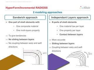
  • 27. Copyright © 2013 Altair Engineering, Inc. Proprietary and Confidential. All rights reserved. HyperForm/Incremental RADIOSS Sandwich approach  One part of shell elements with • One composite material • One multi-layers property  To give tendancies  No sliding between layers  No coupling between warp and weft directions Independant Layers approach  N parts of shell elements • One material law per layer • One property per layer • Contact between layers  More accurate  Sliding between layers  Coupling between warp and weft directions Sandwich approach Independant Layers approach s11 s11 ~ 2 modeling approaches
  • 28. Copyright © 2013 Altair Engineering, Inc. Proprietary and Confidential. All rights reserved. Crash Model Initialization Process 1. Forming Setup: • Die, Binder, Punch & Blank 2. Composite Setup: 3. Computation (RADIOSS) 4. Mapping Approach Selection: Dry or Resin Stacking definition Ply creation Material Orientation are mapped on the different layers 2nd Directions can be mapped for Fabric Blank type selection  Composite Blank config selection  Multilayered Automatic Creation of • Contact interfaces tools and blank(s) • Contact interface between layers • Post-treatment cards in engine
  • 29. Copyright © 2013 Altair Engineering, Inc. Proprietary and Confidential. All rights reserved. Forming influence on Impact Reference Model Model initialized with fiber directions
  • 30. RADIOSS Composite Modeling New Stack & Ply possibility Orientation Review Composite Forming Preliminary Optimization 01 Composite Initialization
  • 31. Copyright © 2013 Altair Engineering, Inc. Proprietary and Confidential. All rights reserved. Preliminary Optimization Aims: Quickly Define Composite Patches before Performance Optimization Solution:  Run OptiStruct Free Size optimization  Convert OptiStruct result to RADIOSS
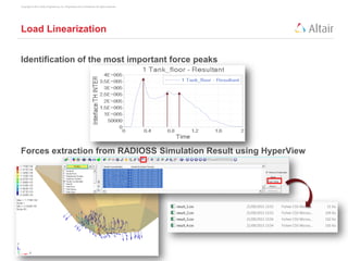
  • 32. Copyright © 2013 Altair Engineering, Inc. Proprietary and Confidential. All rights reserved. Load Linearization Identification of the most important force peaks Forces extraction from RADIOSS Simulation Result using HyperView
  • 33. Copyright © 2013 Altair Engineering, Inc. Proprietary and Confidential. All rights reserved. Equivalent OS Model Set Up MAT 8 1 PCOMPP & Laminate on each face Each laminate composed of 4 plies [0, 90, 45, -45] 3 Load collector corresponding for each force’s peak Inertia RELIEF active
  • 34. Copyright © 2013 Altair Engineering, Inc. Proprietary and Confidential. All rights reserved. Equivalent OS Model Set Up Force Import: ANALYSIS  FORCES
  • 35. Copyright © 2013 Altair Engineering, Inc. Proprietary and Confidential. All rights reserved. Equivalent OS Model Set Up One Design Variable (freeSize) for each laminate Pattern repetition to get the same result on each face Loading is not symmetric Master Master Slaves Slave Objective Min Compliance Constraint Vol Frac < 50%
  • 36. Copyright © 2013 Altair Engineering, Inc. Proprietary and Confidential. All rights reserved. Optimization Result Freesize Total thickness Ply 0° Ply 90° Ply 45° Ply -45°
  • 37. Copyright © 2013 Altair Engineering, Inc. Proprietary and Confidential. All rights reserved. Optimization Result OptiStruct output fem
  • 38. Copyright © 2013 Altair Engineering, Inc. Proprietary and Confidential. All rights reserved. Conversion to RADIOSS Using OptiStruct Non Linear analysis (NLGEOM, EXPDYN), OptiStruct model is converted into RADIOSS input deck (Bulk to Block conversion) • OS Laminates are converted into STACK properties (TYPE 17) • OS Plies are converted into PLY properties (TYPE 19)
  • 39. SPH Modeling ALE Modeling with Multiphasic Law 02 Fluid Modeling
  • 40. Copyright © 2013 Altair Engineering, Inc. Proprietary and Confidential. All rights reserved. Modeling the fluid: main difficulties  Meshing: • The volume may be difficult to mesh with Hexas • Connect the tank to the fluid  Stability • High deformations of the fluid  Solutions : • SPH • ALE
  • 41. Copyright © 2013 Altair Engineering, Inc. Proprietary and Confidential. All rights reserved. Why SPH?  Domain divided by a set of particles tied to their neighbors by internal forces  Lagrangian approach: • Physical laws of mechanics of continuum medium • Material characteristics, velocity and mass assigned to the particles • Interpolation and weight functions for interactions  At each cycle, the “connectivity” changes according to material deformations:  No bad element shape • Less error due to hourglass • Less time step problem
  • 42. Copyright © 2013 Altair Engineering, Inc. Proprietary and Confidential. All rights reserved. SPH model  Particle network • Pitch = 5 mm • Cubic centered network  Connexion between tank and fluid • Type 7 interface • Gap = 2.5 mm • Everything else = default value
  • 43. Copyright © 2013 Altair Engineering, Inc. Proprietary and Confidential. All rights reserved. SPH model
  • 44. Copyright © 2013 Altair Engineering, Inc. Proprietary and Confidential. All rights reserved. Why ALE?  Multiphasic law 51 allows to model air entrapment  Faster than SPH (CPU/element is around 5-6)  Robust method • Insensitive to fluid deformation
  • 45. Copyright © 2013 Altair Engineering, Inc. Proprietary and Confidential. All rights reserved. ALE Features  Fluid and structural mesh are not coincident • Connexion through type 1 interface • Reference with coincident mesh  Free surface defined with /INIVOL  Grid Mesh control • Option /STANDARD  Antidiffusion techniques • SUPG • Phase antidiffusion parameters
  • 46. Copyright © 2013 Altair Engineering, Inc. Proprietary and Confidential. All rights reserved. ALE model
  • 47. Copyright © 2013 Altair Engineering, Inc. Proprietary and Confidential. All rights reserved. ALE model: coincident vs non coincident mesh
  • 48. Copyright © 2013 Altair Engineering, Inc. Proprietary and Confidential. All rights reserved. Comparison ALE vs SPH In the SPH model, the particles are not initially in uniform contact with the tank  2 pressure waves: 1. Tank vs ground 2. (Tank + fluid) vs ground
  • 49. Copyright © 2013 Altair Engineering, Inc. Proprietary and Confidential. All rights reserved. Comparison ALE vs SPH SPH signal was shifted by 0,2 ms to take into account double shock
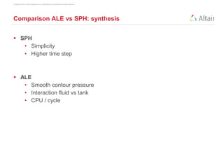
  • 50. Copyright © 2013 Altair Engineering, Inc. Proprietary and Confidential. All rights reserved. Comparison ALE vs SPH: synthesis  SPH • Simplicity • Higher time step  ALE • Smooth contour pressure • Interaction fluid vs tank • CPU / cycle
  • 51. Material Orientation Failed Layers Damage 03 Post Processing of Composite Materials
  • 52. Copyright © 2013 Altair Engineering, Inc. Proprietary and Confidential. All rights reserved. Composite Material Post-Processing Time History • /TH/EMIN, /TH/EMAX – plastic work • /TH/WPLAY_.... plastic work for each layer • Element stress (element coordinate system) Animation • /ANIM/ELEM/EPSP/ALL – plastic work • /ANIM/SHELL/TENS/STRAIN/ALL – strain tensor (global CS) • /ANIM/ SHELL/TENS/STRESS/ALL – stress tensor (global CS) • /ANIM/SHELL/FAIL • /ANIM/SHELL/PHI/ALL – angle between first element direction and first fiber direction • /ANIM/BRICK/ORTHDIR/ALL – Euler angles (, , ) • /ANIM/SHELL/DAMA/ALL (new in v.14) • /ANIM/BRICK/DAMA/ijk (new in v.14)
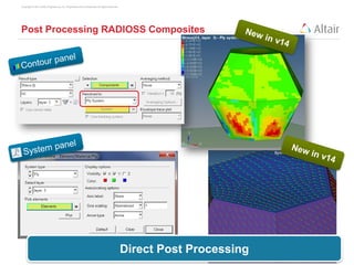
  • 53. Copyright © 2013 Altair Engineering, Inc. Proprietary and Confidential. All rights reserved. Post Processing RADIOSS Composites Direct Post Processing
  • 54. Copyright © 2013 Altair Engineering, Inc. Proprietary and Confidential. All rights reserved. Failed Layers Understanding rupture process
  • 55. Copyright © 2013 Altair Engineering, Inc. Proprietary and Confidential. All rights reserved. Failure Model Damage Value Johnson-Cook failure Tuler-Butcher failure Wilkins failure BAO-XUE-Wierzbicki failure Strain Failure Model with dependence on Lode angle FLD failure Strain failure Specific energy failure CHANG failure HASHIN composite failure PUCK failure NXT Failure Damage Visualisation – D value definition    f p D     K dt D t r  ss   0 f p D dWW D p     0 21    f p D   critD D D            or ormajor time MaxD minlim min              12 11 tt t time MaxD    dmcf eeeeMaxD ,,,  4321 ,,, FFFFMaxD           12 1 E EE MaxD time            1)(,1)( ,1)(,1)(,1)( ModeCeModeBe ModeAencompressioetensilee MaxD ff fff 2 f D  
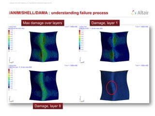
  • 56. Copyright © 2013 Altair Engineering, Inc. Proprietary and Confidential. All rights reserved. /ANIM/SHELL/DAMA : understanding failure process Max damage over layers Damage, layer 1 Damage, layer 8
  • 57. Copyright © 2013 Altair Engineering, Inc. Proprietary and Confidential. All rights reserved. /ANIM/SHELL/DAMA : understanding failure process Max damage over layers Damage, layer 1 Stress tensor Compression « vertical direction » is critical
  • 58. Overview of Equivalent Static Load Method ESLM in RADIOSS or Optistruct RADIOSS block optimization keywords Example optimization Other? 04 Optimization
  • 59. Copyright © 2013 Altair Engineering, Inc. Proprietary and Confidential. All rights reserved. Equivalent Static Load Method • Considering time history and not just worst case time step ft eq = Kdt t d OptiStruct Analysis Dynamic / Nonlinear Problem Load time history Optimization Static Response Problem Equivalent static loads Load Design variables
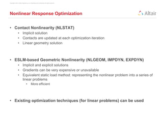
  • 60. Copyright © 2013 Altair Engineering, Inc. Proprietary and Confidential. All rights reserved. Nonlinear Response Optimization • Contact Nonlinearity (NLSTAT) • Implicit solution • Contacts are updated at each optimization iteration • Linear geometry solution • ESLM-based Geometric Nonlinearity (NLGEOM, IMPDYN, EXPDYN) • Implicit and explicit solutions • Gradients can be very expensive or unavailable • Equivalent static load method: representing the nonlinear problem into a series of linear problems • More efficient • Existing optimization techniques (for linear problems) can be used
  • 61. Copyright © 2013 Altair Engineering, Inc. Proprietary and Confidential. All rights reserved. Equivalent Static Load Method • Nonlinear analysis (outer loop), Static optimization (inner loop) • will be determined in order to reach the same response field as nonlinear analysis (including dynamic effects) ft eq = Kdt Start Calculate equivalent static loads Converged No Yes Stop Update design variables Load set feq0 feq1 feq2  feqn Time Step t0 t1 t2  tn time displacement Solve static response optimization Nonlinear Analysis
  • 62. Copyright © 2013 Altair Engineering, Inc. Proprietary and Confidential. All rights reserved. ESLM Workflows OptiStruct Syntax RADIOSS Syntax (new in v13) • RADOPT
  • 63. Copyright © 2013 Altair Engineering, Inc. Proprietary and Confidential. All rights reserved. Solver Integration, RADIOSS block input format OptiStruct reader Build RADIOSS model Run RADIOSS solver Calculate ESLM loads and linear subcases Linear optimization (inner loop) Inner loop converges with updated desvars input.rad (optimization) input_0000.rad (starter) input_0001.rad (engine) Outerloop conv No Stop Yes input.fem (ESL-B2B)Created by Optistruct
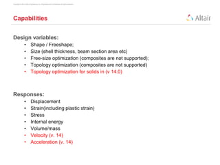
  • 64. Copyright © 2013 Altair Engineering, Inc. Proprietary and Confidential. All rights reserved. Capabilities Design variables: • Shape / Freeshape; • Size (shell thickness, beam section area etc) • Free-size optimization (composites are not supported); • Topology optimization (composites are not supported) • Topology optimization for solids in (v 14.0) Responses: • Displacement • Strain(including plastic strain) • Stress • Internal energy • Volume/mass • Velocity (v. 14) • Acceleration (v. 14)
  • 65. Copyright © 2013 Altair Engineering, Inc. Proprietary and Confidential. All rights reserved. Input design (similar as OptiStruct cards) Objective • /DESOBJ Constraints • /DCONSTR Responses • /DRESP1 • /DRESP2 (v 14.0) Design variables • /DESVAR, /DSIZE, /DTPL, /DTPG, /DSHAPE, /DVGRID Relate design variable with properties • /DVPREL1 Equations • /DEQATN (v 14.0)
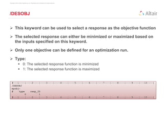
  • 66. Copyright © 2013 Altair Engineering, Inc. Proprietary and Confidential. All rights reserved. /DESOBJ #---1----|----2----|----3----|----4----|----5----|----6----|----7----|----8----|----9----|---10----| /DESOBJ myobj- # type resp_ID 0 1 #---1----|----2----|----3----|----4----|----5----|----6----|----7----|----8----|----9----|---10----|  This keyword can be used to select a response as the objective function  The selected response can either be minimized or maximized based on the inputs specified on this keyword.  Only one objective can be defined for an optimization run.  Type:  0: The selected response function is minimized  1: The selected response function is maximized
  • 67. Copyright © 2013 Altair Engineering, Inc. Proprietary and Confidential. All rights reserved. /DCONSTR  Constrains a design response by specifying its lower and upper bounds.  Cmin: Lower Bound for the constrained response  Cmax: Upper Bound for the constrained response  Unnecessary bounds should be left blank (& not 0) #---1----|----2----|----3----|----4----|----5----|----6----|----7----|----8----|----9----|---10----| /DCONSTR/1 disp constraint # resp_ID cmin cmax 2 19.7742 #---1----|----2----|----3----|----4----|----5----|----6----|----7----|----8----|----9----|---10----|
  • 68. Copyright © 2013 Altair Engineering, Inc. Proprietary and Confidential. All rights reserved. /DRESP1  Defines a response or a set of responses that are a result of a design analysis iteration  They can be used as a design objective or as design constraints  Types: Mass, Volume, Displacement, Stress, Strain, Internal Strain Energy #---1----|----2----|----3----|----4----|----5----|----6----|----7----|----8----|----9----|---10----| /DRESP1/1 min mass # RTYPE PTYPE REGION ATTA ATTB ATTI # mass part grpart 1 3 1 2000329 #---1----|----2----|----3----|----4----|----5----|----6----|----7----|----8----|----9----|---10----| /DRESP1/2 disp19.7742mm # RTYPE PTYPE REGION ATTA ATTB ATTI disp node dir grnod 5 1 2 2021524 #---1----|----2----|----3----|----4----|----5----|----6----|----7----|----8----|----9----|---10----|
  • 69. Copyright © 2013 Altair Engineering, Inc. Proprietary and Confidential. All rights reserved. /DRESP1 - Optimization Design Response, continued
  • 70. Copyright © 2013 Altair Engineering, Inc. Proprietary and Confidential. All rights reserved. /DESVAR  Optimization Design Variables  Xini: Initial Value  Xmin: Lower Bound  Xmax: Upper Bound #---1----|----2----|----3----|----4----|----5----|----6----|----7----|----8----|----9----|---10----| /DESVAR/1 design variable for thick mid reinforcement # Xini Xmin Xmax 0.7 0.5 3.0 #---1----|----2----|----3----|----4----|----5----|----6----|----7----|----8----|----9----|---10----| /DESVAR/2 design variable for thick for inside reinforcement # Xini Xmin Xmax 0.7 0.5 3.0 #---1----|----2----|----3----|----4----|----5----|----6----|----7----|----8----|----9----|---10----|
  • 71. Copyright © 2013 Altair Engineering, Inc. Proprietary and Confidential. All rights reserved. Optimization Design Variables See online help for details about each design variable Keyword Description /DSIZE Free-Size Optimization /DTPL Topology Optimization /DTPG Topography Optimization /DSHAPE Free-Shape Optimization /DVGRID Size Optimization
  • 72. Copyright © 2013 Altair Engineering, Inc. Proprietary and Confidential. All rights reserved. /DVPREL1  Relates Design Variables to Analysis Model Properties  Property Type:  1: /PROP/SHELL  prop_fid: 1 = thickness  2: /PROP/TRUSS  prop_fid: 2 = area  3: /PROP/BEAM  prop_fid: 1 = area, 2 = Iyy, 3 = Izz, 4 = Ixx #---1----|----2----|----3----|----4----|----5----|----6----|----7----|----8----|----9----|---10----| /DVPREL1/1 link_dv_shell_T for mid reinforcement # prop_typ prop_id prop_fid C0 1 2000329 1 0.0 # DVid1 COEF1 1 1.0 #---1----|----2----|----3----|----4----|----5----|----6----|----7----|----8----|----9----|---10----| /DVPREL1/2 link_dv_shell_T for inside reinforcement # prop_typ prop_id prop_fid C0 1 2000327 1 0.0 # DVid1 COEF1 2 1.0 #---1----|----2----|----3----|----4----|----5----|----6----|----7----|----8----|----9----|---10----|
  • 73. Copyright © 2013 Altair Engineering, Inc. Proprietary and Confidential. All rights reserved. /ESLPART – specify parts for ESL optimization By default, the entire RADIOSS model is used in constructing the OptiStruct ESL optimization model. With /ESLPART • Specify part of the RADIOSS model to be used in ESL optimization; • The full RADIOSS model is still used in analysis and design validation (with the optimized part updated).
  • 74. Copyright © 2013 Altair Engineering, Inc. Proprietary and Confidential. All rights reserved. Example SHELL property (PROP/TYPE1) with isotropic material Objective Min MASS Constraint Stress < 450MPa Manufacturing Constraints Cyclic Symmetry
  • 75. Copyright © 2013 Altair Engineering, Inc. Proprietary and Confidential. All rights reserved. Example RADOPT Card Tank wall ID Response definition Variable bounds Stress Constraint Mindim Cyclic Sym
  • 76. Copyright © 2013 Altair Engineering, Inc. Proprietary and Confidential. All rights reserved. Example Cyclic symmetry definition
  • 77. Copyright © 2013 Altair Engineering, Inc. Proprietary and Confidential. All rights reserved. Example Result 6 Optimization Loops
  • 78. Copyright © 2013 Altair Engineering, Inc. Proprietary and Confidential. All rights reserved. DOE Opt RBDO Coupling HyperStudy & RADIOSS • When Optimization must take in account highly non linear phenomena: • Post rupture behavior • Post buckling behavior • Size/Morphing Optimization using HyperStudy • Infinite Exploration with HW Unlimited OS Patch identification RADIOSS Full Non Linear
  • 79. User Process Application to Composite Materials 05 User Failure Criteria
  • 80. Copyright © 2013 Altair Engineering, Inc. Proprietary and Confidential. All rights reserved. Failure Models in RADIOSS Type Description Keyword /FAIL Chang-Chang Failure criteria for composites /CHANG Failure Normal & Tangential for connectors /CONNECT Specific energy Specific energy /ENERGY FLD Forming Limit Diagram /FLD Hashin Composite model /HASHIN Johnson-Cook Ductile failure /JOHNSON Ladeveze delamination Composite delamination /LAD_DAMA NXT Similar to FLD, but based on stresses /NXT Puck Composite model /PUCK Spalling & Johnson-Cook Ductile and spalling /SPALLING Strain failure Damage accumulation using user functions /TAB1 Tuler-Butcher Failure due to fatigue /TBUTCHER Tensile Tensile strain failure /TENSSTRAIN Bao-Xue-Wierzbicki Ductile material /WIERZBICKI Johnson Cook XFEM Johnson-Cook with XFEM /XFEM_JOHNS Failure models are independent and can be coupled with compatible material
  • 81. Copyright © 2013 Altair Engineering, Inc. Proprietary and Confidential. All rights reserved. User Subroutines in dynamic library  Available for :  user windows  user material laws  user failure criteria  user properties  user sensors  Compilation procedure is easy and independent from RADIOSS version  No need to re-link for each RADIOSS version  dynamic libraries are “small” and can be delivered easily to clients  Very easy to manipulate
  • 82. Copyright © 2013 Altair Engineering, Inc. Proprietary and Confidential. All rights reserved. User Subroutines in dynamic library The RADIOSS Userlib SDK – Generate the dynamical library : libraduser_linux64.so / libraduser_win64.dll Located in HyperWorks : hwsolvers/radioss/userlib_sdk  Available on Linux & Windows  2 Compilers for each OS  INTEL COMPILER (Recommended)  Open Source compiler (since Radioss 14) GNU Fortran – Linux • MinGW – Windows  SDK contains :  Compiling Scripts  Some Interface libraries Needed to generate the Library Set 2 Environment variables & invoke the Script : RAD_USERLIB_SDK_PATH : Sdk Root name RAD_USERLIB_ARCH : OS & Compiler choice ********************************************* ** Generating Radioss Dynamic User Library ** ********************************************* Preparing Library ----------------- Compiling: lecm29.F ---------- lecm29.F Compiling: sigeps29c.F ---------- sigeps29c.F Creating library: libraduser_win64.dll ---------------- Creating library libraduser_win64.lib and object libraduser_win64.exp Done ----
  • 83. Copyright © 2013 Altair Engineering, Inc. Proprietary and Confidential. All rights reserved. Radioss Starter and Engine load the library if available ! Location is either:  RAD_USERLIB_LIBPATH (RADIOSS V14)  Local Directory (RADIOSS V14)  LD_LIBRARY_PATH (Linux) / PATH (Windows) Or can be loaded with –dylib command line option (RADIOSS V14)  This option permits to use an alternate library name. When library is successfully loaded,  Library information is printed in out files.  When Dataset contains User Carts, Routines in the Library are invoked User Subroutines in dynamic library EXTERNAL LIBRARY FOR USERS CODE INTERFACE ----------------------------------------- LIBRARY NAME . . . . . . . . . . . . . . . . . libraduser_win64.dll RADIOSS USERS CODE INTERFACE VERSION . . . . .1301501260 RADIOSS Libraduser_win64.dll
  • 84. Copyright © 2013 Altair Engineering, Inc. Proprietary and Confidential. All rights reserved. How to use the dynamic library? Move the dynamic library in the model directory Or copy your dynamic library to your RADIOSS install directory: HW_Installation_directoryhwsolversbinwin64 Note : if there are dynamic libraries in both directories, the RADIOSS install directory ones have priority.
  • 85. Copyright © 2013 Altair Engineering, Inc. Proprietary and Confidential. All rights reserved. Failure criteria  3 user failure criteria are available • /FAIL/USER1 • /FAIL/USER2 • /FAIL/USER3  3 subroutines / failure criteria : • Lecr04 : starter, USER1 • f04law : solver calculation solids (USER1) • f04lawc : solver calculation for shell (USER1) • 05 for USER2, 06 for USER3  Very similar to user material laws (variable names …)
  • 86. Copyright © 2013 Altair Engineering, Inc. Proprietary and Confidential. All rights reserved. Example: Orthotropic failure strain 12 /FAIL/USER1/32 # eps1ini eps1f .01 .012 # eps2ini eps2f .01 .012 # eps12ini eps12f .10 .15  Purpose :  Degradation and possible deletion of element as a function of several variables (stress, strain, user variables …)
  • 87. Copyright © 2013 Altair Engineering, Inc. Proprietary and Confidential. All rights reserved. Example: Orthotropic failure strain SUBROUTINE LECR04 (IIN ,IOUT ,UPARAM ,MAXUPARAM,NUPARAM, 1 NUVAR,IFUNC,MAXFUNC,NFUNC) Variable declaration READ(IIN,"(2F20.0)")eps1ini,eps1f READ(IIN,"(2F20.0)")eps2ini,eps2f READ(IIN,"(2F20.0)")eps12ini,eps12f NUPARAM = 6 UPARAM(1) = eps1ini UPARAM(2) = eps1f UPARAM(3) = eps2ini UPARAM(4) = eps2f UPARAM(5) = eps12ini UPARAM(6) = eps12f WRITE(IOUT, 1100) WRITE(IOUT, 1100) eps1ini,eps1f WRITE(IOUT, 1200) eps2ini,eps2f 1000 FORMAT( & 5X,' USER ORTHOTROPIC FAILURE CRITERIA',/, & 5X,' --------------------------------- ',//) 1100 FORMAT( & 5X,'STRAIN THRESHOLD FOR DIRECTION 1. . .=',E12.4/, & 5X,'STRAIN MAX FOR DIRECTION 1. . . . . .=',E12.4/) 1200 FORMAT( & 5X,'STRAIN THRESHOLD FOR DIRECTION 2. . .=',E12.4/, & 5X,'STRAIN MAX FOR DIRECTION 2. . . . . .=',E12.4/) 1300 FORMAT( & 5X,'STRAIN THRESHOLD FOR DIRECTION 12 . .=',E12.4/, & 5X,'STRAIN MAX FOR DIRECTION 12 . . . . .=',E12.4/) RETURN END  Starter: lecr04  read input file (0.rad)
  • 88. Copyright © 2013 Altair Engineering, Inc. Proprietary and Confidential. All rights reserved. Example: Orthotropic failure strain SUBROUTINE ( 1 NEL ,NUPARAM ,NUVAR ,NFUNC ,IFUNC,NPF, 2 TF ,TIME ,TIMESTEP ,UPARAM ,NGL ,IPT, 3 NPT0 ,NOT_USE_I1,NOT_USE_I2 ,NOT_USE_I3, 4 SIGNXX ,SIGNYY ,SIGNXY ,SIGNYZ ,SIGNZX , 4 EPSPXX ,EPSPYY ,EPSPXY ,EPSPYZ ,EPSPZX , 6 EPSXX ,EPSYY ,EPSXY ,EPSYZ ,EPSZX , 7 PLA ,DPLA ,EPSP ,UVAR ,UEL , 8 OFF ,NOT_USED1 ,NOT_USED2,NOT_USED3,NOT_USED4,NOT_USED5 ) Variable declaration eps1ini = UPARAM(1) eps1f = UPARAM(2) eps2ini = UPARAM(3) eps2f = UPARAM(4) eps12ini = UPARAM(5) eps12f = UPARAM(6) DO I =1,NEL IF((OFF(I).EQ.1.0 ).AND. (EPSXX(I).GE.eps1ini)) THEN d11(I) = (EPSXX(I) - eps1ini ) / (eps1f - eps1ini) d11f(I) = min(1.0 , d11(I)) SIGNXX(I) = (1.0 - d11f(I))*SIGNXX(I) ENDIF Same for directions 12, 22 ENDDO C RETURN END  Engine : f04law (for solid elements)
  • 89. Copyright © 2013 Altair Engineering, Inc. Proprietary and Confidential. All rights reserved. Example: Orthotropic failure strain  Engine : f04law (for solid element deletion) C Total Failure IF((OFF(I).EQ.1.0) .AND. (ABS(EPSXY(I)).GE.eps12f)) THEN OFF(I) = 0.9999 ENDIF IF((OFF(I).EQ.1.0 ).AND. (EPSXX(I).GE.eps1f)) THEN OFF(I) = 0.9999 ENDIF IF((OFF(I).EQ.1.0 ).AND. (EPSYY(I).GE.eps2f)) THEN OFF(I) = 0.9999 ENDIF SIGNXX(I) = SIGNXX(I) * OFF(I) SIGNYY(I) = SIGNYY(I) * OFF(I) SIGNXY(I) = SIGNXY(I) * OFF(I) IF (OFF(I).LT.1.0) THEN OFF(I) = OFF(I)*0.9 IF (OFF(I).LT.0.1) OFF(I)=0.0 ENDIF RETURN END
  • 90. Copyright © 2013 Altair Engineering, Inc. Proprietary and Confidential. All rights reserved. Example: Orthotropic failure strain  Application
  • 91. Thank you for your attention RADIOSS Composite Materials & Optimization