SlideShare a Scribd company logo
UNIT 4 - ROBOT KINEMATICS AND ROBOT PROGRAMMING
ME8099 – ROBOTICS
(Professional elective-III)
Mr. TAMIL SELVAN M, A/P, MECH, KIT.
WELCOME
UNIT IV ROBOT KINEMATICS AND
ROBOT PROGRAMMING
Forward Kinematics, Inverse Kinematics and Difference;
Forward Kinematics and Reverse Kinematics of manipulators
with Two, Three Degrees of Freedom (in 2 Dimension), Four
Degrees of freedom (in 3 Dimension) Jacobians, Velocity and
Forces-Manipulator Dynamics, Trajectory Generator,
Manipulator Mechanism Design-Derivations and problems. Lead
through Programming, Robot programming Languages-VAL
Programming-Motion Commands, Sensor Commands, End
Effector commands and simple Programs
KINEMATICS
KINEMATICS – the analytical study of the geometry of
motion of a mechanism:
• with respect to a fixed reference co-ordinate system,
• without regard to the forces or moments that cause the motion.
In order to control and programme a robot we must have
knowledge of both its spatial arrangement and a means of
reference to the environment.
FORWARD KINEMATICS
 A manipulator is composed of serial links which are affixed to each
other revolute or prismatic joints from the base frame through the
end-effector.
 Calculating the position and orientation of the end-effector in terms
of the joint variables is called as forward kinematics.
 In order to have forward kinematics for a robot mechanism in a
systematic manner, one should use a suitable kinematics model.
 Denavit-Hartenberg method that uses four parameters is the most
common method for describing the robot kinematics.
 These parameters ai-1, α −1i , di and θi are the link length, link twist,
link offset and joint angle, respectively.
 A coordinate frame is attached to each joint to determine DH
parameters.
 Zi axis of the coordinate frame is pointing along the rotary or sliding
direction general manipulator.
INVERSE KINEMATICS
 The inverse kinematics problem of the serial manipulators has
been studied for many decades.
 It is needed in the control of manipulators.
 Solving the inverse kinematics is computationally expansive
and generally takes a very long time in the real time control of
manipulators.
 Tasks to be performed by a manipulator are in the Cartesian
space, whereas actuators work in joint space.
 Cartesian space includes orientation matrix and position vector.
However, joint space is represented by joint angles.
 The conversion of the position and orientation of a manipulator
end-effector from Cartesian space to joint space is called as
inverse kinematics problem.
 There are two solutions approaches namely, geometric and
algebraic used for deriving the inverse kinematics solution,
analytically.
Forward Kinematics
(angles to position)
Inverse Kinematics
(position to angles)
What you are given: The length of each link
The angle of each joint
The length of each link
The position of some point
on the robot
What you can find: The position of any point
(i.e. it’s (x, y, z) coordinates
The angles of each joint
needed to obtain that
position
ROBOTICS-ROBOT KINEMATICS AND ROBOT PROGRAMMING
FORWARD KINEMATIC TRANSFORMATION
OF TWO DEREES OF FREEDOM
 The transformation of coordinates of the end-effector point from the joint
space to the world space is known as forward kinematics transformation.
 LL ROBOT
 RR ROBOT
 TL ROBOT
LL ROBOT
 Joints J1 and J2 are linear joints with links of variable length L1 and
L2. Let joint J1 be denoted by (x1, y1) and joint J2 (x2, y2)
ROBOTICS-ROBOT KINEMATICS AND ROBOT PROGRAMMING
RR ROBOT
ROBOTICS-ROBOT KINEMATICS AND ROBOT PROGRAMMING
INVERSE KINEMATIC OF TRANSFORMATION
OF 2 DEGREE OF FREEDOM
ROBOTICS-ROBOT KINEMATICS AND ROBOT PROGRAMMING
Forward and Reverse kinematics
transformation for RR robot with 2 DOF with 2D
ROBOTICS-ROBOT KINEMATICS AND ROBOT PROGRAMMING
Forward and Reverse kinematics of spherical
robot RRL configuration with 2 DOF with 2D
ROBOTICS-ROBOT KINEMATICS AND ROBOT PROGRAMMING
FORWARD KINEMATICS FOR 2 DEGREE
OF FREEDOM WITH 2 DIMENSIONS
ROBOTICS-ROBOT KINEMATICS AND ROBOT PROGRAMMING
INVERSE KINEMATICS FOR 2 DEGREE
OF FREEDOM WITH 2 DIMENSIONS
ROBOTICS-ROBOT KINEMATICS AND ROBOT PROGRAMMING
FORWARD KINEMATICS FOR 3 DEGREE
OF FREEDOM WITH 2 DIMENSIONS
ROBOTICS-ROBOT KINEMATICS AND ROBOT PROGRAMMING
INVERSE KINEMATICS FOR 3 DEGREE
OF FREEDOM WITH 2 DIMENSIONS
ROBOTICS-ROBOT KINEMATICS AND ROBOT PROGRAMMING
Forward and inverse kinematics of manipulators
with 4 Degrees of Freedom in 3 Dimension
 A 4-Degree of Freedom Manipulator in (3D) Three Dimensions:
 The configuration of a manipulator in three dimensions. The
manipulator has 4 degrees of freedom: joint I (type T joint) allows
rotation about the z axis; joint 2 (type R) allows rotation about an
axis that is perpendicular to the z axis; joint 3 is a linear joint
which is capable of sliding over a certain range; and joint 4 is a
type R joint which allows rotation about an axis that is parallel to
the joint 2 axis. Thus, we have a TRL: R manipulator.
ROBOTICS-ROBOT KINEMATICS AND ROBOT PROGRAMMING
 Let us define the angle of rotation of joint I to be the base rotation 0;
the angle of rotation of joint 2 will be called the elevation angle 4.;
 The length of linear joint 3 will be called the extension L (L-represents
a combination of links 2 and 3);
 and the angle that joint 4 makes with the x — y plane will be called
the pitch angle 4.
 The position of the end of the wrist, P, defined in the world coordinate
system for the robot.
ROBOTICS-ROBOT KINEMATICS AND ROBOT PROGRAMMING
ROBOT PROGRAMMING:
“Robot Programming is a art of teaching a robot online or offline
a series of tasks to be performed with required accuracy,
velocity and repeatability.”
GENERAL ROBOT PROGRAMMING
PARADIGM
METHODS OF TRAINING ROBOTS
1. Lead through programming used for servo-controlled robots
 Teach-by-guiding
 Teach by teach- box methods
a. Point-to-point
- Move robot to each point in task and record it.
b. Continuous-path
- Move robot through entire task at normal speed while the robot records its
position many times a second.
METHODS OF TRAINING ROBOTS
2. Off-line programming used for servo-controlled robots
a. Transfer from another robot that already knows how to do
task.
b. operators write the task programs with step-by-step
procedure in some programming language
3. Robot Simulation
TEACH BY GUIDING
 It is some times also called as lead through programming.
 Primarily this method is highly suitable for programming the
continuous path robots.
 It can be done with simple equipment and controls.
 Also, the teaching is performed quickly and is immediately useful.
 In the playback mode, the robot repeats the path and operations
that were stored in memory during the teach operation.
TEACH BY GUIDING
 In some systems, it is possible to play back at different speeds than
the speed that was used in the teach mode.
 Each movement is recorded into the memory for the playback
during production.
 A person doing the programming has physical contacts with the
robot arm, actually gains control and walks the robot's arm through
the desired positions.
TEACH BY GUIDING
 The main concern is on achieving the correct positioning
sequences.
 Cycle time and speed can be changed later, when necessary.
 A dead man’s control should be fitted for the safety reason.
 Every operator motion is recorded and played back in the same
manner, including unintended motions.
DISADVANTAGES TO TEACH-BY-GUIDING:
 It is difficult to incorporate sensory information.
 It cannot be used in some hazardous situations.
 It is not practical in handling large robots.
 Since teaching is performed manually, high precision in generating
paths con not be achieved.
 Synchronization with other operations/device/external sensor may
be difficult.
TEACHING BY TEACH - BOX METHOD
(TEACHING AND PENDANT CONTROL)
 Teaching the robot via teach pendants that has toggle switches or
contact buttons for controlling the movement of the robot.
TEACHING BY TEACH - BOX METHOD
(TEACHING AND PENDANT CONTROL)
 Moving the robot arm to each specific point manually and pressing
a button to record the coordinates of that point do teaching in point-
to-point systems.
 Encoders, potentiometers, or other means does position
measurement.
 Large robot arms are often counterbalanced to make manual
movement easier. Some large robots have an auxiliary lightweight
arm that can be used for training or guidance.
TEACHING BY TEACH - BOX METHOD
(TEACHING AND PENDANT CONTROL)
 The teach pendant can control all axes of the robot arm in terms of
position and movement velocity.
 Pendant controls are especially useful for large robots that might
otherwise be difficult to take through the training cycle.
 They are also useful in applications in dangerous environments.
TEACHING BY TEACH - BOX METHOD
(TEACHING AND PENDANT CONTROL)
 In addition, they are more convenient for many purposes other than
manual movement, so the use of pendant control has increased in
the last few years.
 The main disadvantage of this method is that the equipment is tied
up in the programming stage.
 However because of simplicity this method is widely accepted in
industry, especially in PTP applications such as machine loading
and unloading, spot welding, simple assembly tasks.
ADVANTAGES DISADVANTAGES
Shop personnel can readily
learn it, does not require deeper
programming experience
• Logical way to learn
Production must be interrupted
– Teach pendant have limitations in the
amount of decision making logic that
can be incorporated into the program
– No interface to other computer
subsystems in the factory (no CIM).
ROBOT PROGRAMMING LANGUAGES
This section will review the evolution of robot languages like
MH1,
WAVE,
VAL,
PAL,
RAIL,
HELP,
JARS,
RPL and
MCL
1. MH1 (MECHANICAL HAND ONE)
 The first robot language capable of describing operations with
programmable commands, developed at MIT by H. A. Ernst
The available language commands are:
 MOVE - indicating a direction and speed
 UNTIL - operate until a specific sensor condition occurs
 IF GOTO - branch to a new location in the program on a specific
condition
 IF CONT - branch to continue action on a specific condition
2. WAVE
 WAVE, developed at Stanford University, was the first general
purpose robot programming system.
The most important features were:
 1. Specification of compliance capability in Cartesian coordinates.
 2. Coordination of joint motions to provide for continuity of velocities
and accelerations through trajectory turning points or via points.
 3. Description of end effector positions in Cartesian coordinates.
 4. Guarded move capability, so that sensory information could be
used to terminate a move when the end effector touched
something.
3. AL (ASSEMBLY LANGUAGE)
 AL is a high-level programming system for specification of
manipulator tasks such as automatic assembly in production line
manufacturing.
 AL has a considerable effect on other languages and has emerged
as one of the leading contenders for a common robotic language.
 It was developed at Stanford University in 1974 and has been
improved and tested since then.
3. AL (ASSEMBLY LANGUAGE)
 It has an ALGOL-like source language, a translator to convert
programs into run able code, and a runtime system for controlling
manipulators and other devices.
 Trajectory calculations are done at compile time and are modified
during runtime as necessary.
 Two or more objects can be handled as one by the use of AFFIX
commands that cause them to appear as one object.
3. AL (ASSEMBLY LANGUAGE)
 Force sensing and compliance are implemented by a number of
subroutines and by condition monitor statements in the syntax of
the language.
 There are signal statements and wait statements available when
one process must wait for the completion of another process.
 These and other statements make possible the coordinated
operation of two or more robot arms.
 Arm and hand movement commands are available to control
moves, velocities, forces, and torques.
4. PLAW
(Programming Languages for Arc Welding).
 A robot manufacturing company, Komatsu developed it for its series
RW Cartesian robots, equipped with arc current and television.
 This is a low-level language specifically developed to program an
adaptive welding robot.
 It primarily serves to simplify the programming of complex
operations.
 In contrast to AL, this language does not call for the use of a large
computer (it can well be implemented with a microcomputer).
4. PLAW
(Programming Languages for Arc Welding).
PLAW includes the following instructions:
 -Robot motion control (point-to-point, using various interpolation
techniques)
 -Control of welding equipment
 -Control of peripherals (by turning ON and OFF the respective
channels)
 -Control of sensor systems
 -Service instructions
 -Conditional and unconditional jump instructions. Conditional jump
instructions check the status of flags and perform the respective
branch action
5. AML (A Manufacturing Language)
 AML was developed in 1976 at IBM’s T.J. Watson Research Labs
for assembly related tasks.
 AML provides a systems environment in which different user robot
programming interfaces may be built.
 It supports joint space trajectory planning, subject to position and
velocity constraints.
 Relative and absolute motion can be handled, and sensor
monitoring can interrupt motions as necessary.
5. AML (A Manufacturing Language)
 The most unique capability of AML is its operations on data
aggregates, so that many operations on vectors, rotations, and
coordinate frames can be handled as multiple operations in one
command.
 This capability makes the language more difficult to understand but
simplifies programming and control.
6. PASCAL
 It is a standard programming language developed by Blazie Pascal
for data processing that uses structured statements to organize the
program in a modular and efficient way.
 The structured statements force the program into separate modules
to reduce the number of branches.
 Each module is self-contained and can be entered only at the top
and exited only at the bottom, so that errors due to branching
mistakes are easier to catch and eliminate.
6. PASCAL
 Data types are the descriptors that identify elements in the
language such as INTEGERS, REAL NUMBERS, and
CHARACTERS.
 It is a well-known and widely used language, and was chosen as
the basis for several robot languages.
7. PAL
 Richard Paul, added capabilities to PASCAL to WAVE and the AL
language provide a new type of programming language PAL.
 This allowed them to take advantage of the proven, well-known
PASCAL language and yet provide new capability.
 In the PAL data structure, the relationship between the arm and the
object can be given explicitly by the use of homogeneous matrix
transforms.
7. PAL
 Every motion statement in PAL causes the manipulator position and
orientation to be specified in an equation representing a closed
kinematic chain.
 An interesting and potentially valuable capability of PAL is the ease with
which unknown points can be picked up from a task and incorporated
into the program.
 Every motion statement in PAL causes the solution of homogeneous
equations that represent the position of the kinematic chain of links and
joints in the arm.
8. MCL
 MCL was developed in 1978 by McDonnell-Douglas in conjunction
with Cincinnati Milacron for an Air Force ICAM Project.
 This language is based on APT, the control language for numerically
controlled (NC) machine tools used in CAM.
 One of its advantages is that a large number of programmers already
use APT in CAM applications.
 APT has specific constructs to specify POINTS, LINES, PATTERNS,
and so on, which are useful in enabling robots to communicate and
cooperate with machine tools.
9. RAIL
 It was developed by Automatix Inc., for the control of both vision
and manipulation.
 It contains a large subset of PASCAL commands and can handle a
variety of data types.
 An interpreter is used to convert the language constructions to
machine language commands.
 Inspection, arc welding and vision operations are supported by
language capabilities. It is run on a powerful Motorola system.
10. RPL
 RPL was designed at SRI (Stanford Research Institute) specifically
for unskilled programmers, factory production engineers, line
foremen, and so on.
 It is a low level language.
 It has a compiler to produce interpretable code from programs and
an interpreter for that code.
 The language is implemented as subroutine calls, so that it is
modular and flexible in use.
10. RPL
 It has been used to control a Unimation PUMA 500 arm and the
Machine Intelligence Corporation (MIC) vision module.
 Some of the ideas of the LISP language are used but are organized
into a FORTRAN-like syntax.
 (LISP is a language designed for artificial intelligence use. It is
primarily recursive and is especially well adapted to handling lists of
information.)
11. ADA
 ADA was developed by Ada Lovelace for the Department of
Defense (DOD) in 1978.
 It has been specified by DOD as the sole system implementation
language for the programming of real-time embedded systems.
 Chief advantages of ADA are the powerful data structures provided
the ability to separate control operations from data operations, and
the inherent capability for concurrent operation of many tasks.
11. ADA
 Concurrent operation is an important requirement for the efficient
use of multiple robots and other equipment.
 The ADA is well suited to the control of manufacturing cells using
robots.
 In addition, ADA is expected to provide code that is easily
transferred between computers and can be easily maintained.
12. VAL (important among all languages)
 Another language developed by augmentation of an existing
language (BASIC) is VAL, developed by Victor Scheinman for the
Unimation Corporation in the year 1975.
 VAL uses simple words to describe operations to be performed by the
robot which leads to real time programming as given below:
 Specify and transform the coordinates of positioning points both in a
Cartesian system and joint angles.
 Edit robot programs written in VAL.
 Manage the execution of user programs.
12. VAL
 VAL provides for speed control, grasping, arm movement, and signaling in
a simple, easy-to-understand framework. Of course, all of these routines
are implemented by subroutines written in BASIC and translated by an
interpreter.
 Higher efficiency could be obtained by the use of a compiled BASIC if
necessary, but usually it is sufficient to call precompiled subroutines.
 The need for a signal to other robots and machines is handled effectively
by the use of the interlock commands such as WAIT, SIGNAL and DELAY,
which take action on the occurrence of specific events.
12. VAL
 VAL is a low level language and calls there fore for detailed planning
of all actions.
 VAL provides the executing commands suitable for PUMA robot for
the applications in assembly, arc welding, spray painting and
material handling.
 In VAL, both teaching (Interlock commands) and offline programming
can be used in an effective way.
 This language is modified into VAL II by adding some more
instructions for the operator convenience.
MOTION PROGRAMMING – STATEMENTS
(VAL) (EXAMPLE)
 MOVE P1 // move to variable P1
 LEARN P1 //(236,158,65,0,0,0) recorded coordinates
 MOVES P1 //(straight line motion) - e.g. MoveL
 DMOVE (4, 125) // incremental move joint 4, 125 mm
MOTION PROGRAMMING – STATEMENTS
(VAL) (EXAMPLE)
 DEFINE PATH123 = PATH(P1,P2,P3)
 MOVE PATH123
Initial statements:
– SPEED 0.5 MPS
– EXECUTE PROGRAM1
SPEED 75 –( 75 %) – ARLA H75%, Rapid v xxx.
OTHER PROGRAMMING STATEMENTS
(EXAMPLE)
Interlock and sensor commands
– WAIT 20, ON // wait until signal on port 20 is ON
– SIGNAL 10, ON // switch signal 10 ON
– SIGNAL 10, 6.0 // switch signal 10 analog to 6 volts
– OPEN
– CLOSE // open and close gripper
Computations and program logic
– GO TO 150
– IF (logical expression) GO TO 150
WELDING INSTRUCTIONS (VAL)
(EXAMPLE)
 WSET command set the speed, welding voltage and current as a
welding condition identified by a number 1 to 4
 WSTART starts welding under present welding condition and
weaving condition.
 WEND inactivates a welding start signal. For example, WEND 0.5
means the welding stops for 0.5 seconds.
 CRATERFILL instruction is used when crater filling is required at a
welding end of the weldment.
Ad

More Related Content

What's hot (20)

Introduction to robotics
Introduction to roboticsIntroduction to robotics
Introduction to robotics
shalet kochumuttath Shaji
 
Fundamental of robotic manipulator
Fundamental of robotic manipulatorFundamental of robotic manipulator
Fundamental of robotic manipulator
snkalepvpit
 
Robot Configuration - 1
Robot Configuration - 1Robot Configuration - 1
Robot Configuration - 1
Manipal Academy of Higher Education (MAHE)
 
Unit-I Robotics
Unit-I RoboticsUnit-I Robotics
Unit-I Robotics
Muthukumar V
 
Chapter 8 - Robot Control System
Chapter 8 - Robot Control SystemChapter 8 - Robot Control System
Chapter 8 - Robot Control System
Haffiz Radzi
 
Robotics and Autoamtion_ manipulators, actuators and end effectors
Robotics and Autoamtion_ manipulators, actuators and end effectorsRobotics and Autoamtion_ manipulators, actuators and end effectors
Robotics and Autoamtion_ manipulators, actuators and end effectors
JAIGANESH SEKAR
 
Trajectory
TrajectoryTrajectory
Trajectory
Anand Sreekantan Thampy
 
Robotics
RoboticsRobotics
Robotics
Deepam Goyal
 
Industrial robotics
Industrial roboticsIndustrial robotics
Industrial robotics
Prasanth Kumar RAGUPATHY
 
Manipulator kinematics
Manipulator kinematicsManipulator kinematics
Manipulator kinematics
Sudhir Reddy
 
Robot Arm Kinematics
Robot Arm KinematicsRobot Arm Kinematics
Robot Arm Kinematics
cairo university
 
Robot control
Robot controlRobot control
Robot control
Hiran Gabriel
 
Industrial applications of robots
Industrial applications of robotsIndustrial applications of robots
Industrial applications of robots
CKSunith1
 
Robotics: Cartesian Trajectory Planning
Robotics: Cartesian Trajectory PlanningRobotics: Cartesian Trajectory Planning
Robotics: Cartesian Trajectory Planning
Damian T. Gordon
 
Robotics - unit-2-- Drive Systems
Robotics - unit-2-- Drive SystemsRobotics - unit-2-- Drive Systems
Robotics - unit-2-- Drive Systems
Dr.G.Saravanan
 
Robotics and machine vision system
Robotics and machine vision systemRobotics and machine vision system
Robotics and machine vision system
Gowsick Subramaniam
 
RMV robot programming
RMV robot programmingRMV robot programming
RMV robot programming
anand hd
 
Robot programming , accuracy ,repeatability and application
Robot programming , accuracy ,repeatability  and applicationRobot programming , accuracy ,repeatability  and application
Robot programming , accuracy ,repeatability and application
vishaldattKohir1
 
Hydraulic and Pneumatic Drive System
Hydraulic and Pneumatic Drive SystemHydraulic and Pneumatic Drive System
Hydraulic and Pneumatic Drive System
turna67
 
Robo unit4- Robot Programming.pptx
Robo unit4- Robot Programming.pptxRobo unit4- Robot Programming.pptx
Robo unit4- Robot Programming.pptx
Priya429658
 
Fundamental of robotic manipulator
Fundamental of robotic manipulatorFundamental of robotic manipulator
Fundamental of robotic manipulator
snkalepvpit
 
Chapter 8 - Robot Control System
Chapter 8 - Robot Control SystemChapter 8 - Robot Control System
Chapter 8 - Robot Control System
Haffiz Radzi
 
Robotics and Autoamtion_ manipulators, actuators and end effectors
Robotics and Autoamtion_ manipulators, actuators and end effectorsRobotics and Autoamtion_ manipulators, actuators and end effectors
Robotics and Autoamtion_ manipulators, actuators and end effectors
JAIGANESH SEKAR
 
Manipulator kinematics
Manipulator kinematicsManipulator kinematics
Manipulator kinematics
Sudhir Reddy
 
Industrial applications of robots
Industrial applications of robotsIndustrial applications of robots
Industrial applications of robots
CKSunith1
 
Robotics: Cartesian Trajectory Planning
Robotics: Cartesian Trajectory PlanningRobotics: Cartesian Trajectory Planning
Robotics: Cartesian Trajectory Planning
Damian T. Gordon
 
Robotics - unit-2-- Drive Systems
Robotics - unit-2-- Drive SystemsRobotics - unit-2-- Drive Systems
Robotics - unit-2-- Drive Systems
Dr.G.Saravanan
 
Robotics and machine vision system
Robotics and machine vision systemRobotics and machine vision system
Robotics and machine vision system
Gowsick Subramaniam
 
RMV robot programming
RMV robot programmingRMV robot programming
RMV robot programming
anand hd
 
Robot programming , accuracy ,repeatability and application
Robot programming , accuracy ,repeatability  and applicationRobot programming , accuracy ,repeatability  and application
Robot programming , accuracy ,repeatability and application
vishaldattKohir1
 
Hydraulic and Pneumatic Drive System
Hydraulic and Pneumatic Drive SystemHydraulic and Pneumatic Drive System
Hydraulic and Pneumatic Drive System
turna67
 
Robo unit4- Robot Programming.pptx
Robo unit4- Robot Programming.pptxRobo unit4- Robot Programming.pptx
Robo unit4- Robot Programming.pptx
Priya429658
 

Similar to ROBOTICS-ROBOT KINEMATICS AND ROBOT PROGRAMMING (20)

JHDFGDFHDFHKJGFGFJGHJ.ppFDGFDDGGFFGDFGDFtx
JHDFGDFHDFHKJGFGFJGHJ.ppFDGFDDGGFFGDFGDFtxJHDFGDFHDFHKJGFGFJGHJ.ppFDGFDDGGFFGDFGDFtx
JHDFGDFHDFHKJGFGFJGHJ.ppFDGFDDGGFFGDFGDFtx
karthicks381361
 
types of robots.pptx
types of robots.pptxtypes of robots.pptx
types of robots.pptx
Shashikanth Boorla
 
Robotics my seminar
Robotics my seminarRobotics my seminar
Robotics my seminar
Punithashunmugam
 
Robots
RobotsRobots
Robots
sushma chinta
 
Unit IV.pptx Robot programming and Languages
Unit IV.pptx Robot programming and LanguagesUnit IV.pptx Robot programming and Languages
Unit IV.pptx Robot programming and Languages
Balamech4
 
robot_program.ppt
robot_program.pptrobot_program.ppt
robot_program.ppt
ssuserc8fc691
 
Industrial Robotics Chap 01 Fundamentals
Industrial  Robotics  Chap 01  FundamentalsIndustrial  Robotics  Chap 01  Fundamentals
Industrial Robotics Chap 01 Fundamentals
Kevin Carvalho
 
B.Tech 5th Semester Industrial Robotics Notes Module- V
B.Tech 5th Semester Industrial Robotics Notes Module- VB.Tech 5th Semester Industrial Robotics Notes Module- V
B.Tech 5th Semester Industrial Robotics Notes Module- V
KameshMechrocks3
 
Robotics unit4 slides
Robotics unit4 slidesRobotics unit4 slides
Robotics unit4 slides
Janarthanan B
 
L010338894
L010338894L010338894
L010338894
IOSR Journals
 
Robotics corporate-training-in-mumbai
Robotics corporate-training-in-mumbaiRobotics corporate-training-in-mumbai
Robotics corporate-training-in-mumbai
Unmesh Baile
 
0234
02340234
0234
Baron Y.S. Yong
 
Robot programming
Robot programmingRobot programming
Robot programming
Gopal Saini
 
A Design Of Omni-Directional Mobile Robot Based On Mecanum Wheels
A Design Of Omni-Directional Mobile Robot Based On Mecanum WheelsA Design Of Omni-Directional Mobile Robot Based On Mecanum Wheels
A Design Of Omni-Directional Mobile Robot Based On Mecanum Wheels
IJRESJOURNAL
 
ie450pp8 jsjdjoscoxlmlxmmxmxlmxclmnlcm lmclvxlc
ie450pp8 jsjdjoscoxlmlxmmxmxlmxclmnlcm lmclvxlcie450pp8 jsjdjoscoxlmlxmmxmxlmxclmnlcm lmclvxlc
ie450pp8 jsjdjoscoxlmlxmmxmxlmxclmnlcm lmclvxlc
sailavanyar1
 
Introduction of Robotics and configuration.ppt
Introduction of Robotics and configuration.pptIntroduction of Robotics and configuration.ppt
Introduction of Robotics and configuration.ppt
CCEnotes
 
INTRODUCTION TO ROBOTICS a common view : robotics
INTRODUCTION TO ROBOTICS a common view : roboticsINTRODUCTION TO ROBOTICS a common view : robotics
INTRODUCTION TO ROBOTICS a common view : robotics
Nagarjunakonduru2
 
INTRODUCTION TO ROBOTICS a common view : robotics
INTRODUCTION TO ROBOTICS a common view : roboticsINTRODUCTION TO ROBOTICS a common view : robotics
INTRODUCTION TO ROBOTICS a common view : robotics
Nagarjunakonduru2
 
UNIT 6 Robotics01.ppt
UNIT 6 Robotics01.pptUNIT 6 Robotics01.ppt
UNIT 6 Robotics01.ppt
nachiketkale5
 
Navigation and Trajectory Control for Autonomous Robot/Vehicle (mechatronics)
Navigation and Trajectory Control for Autonomous Robot/Vehicle (mechatronics)Navigation and Trajectory Control for Autonomous Robot/Vehicle (mechatronics)
Navigation and Trajectory Control for Autonomous Robot/Vehicle (mechatronics)
Mithun Chowdhury
 
JHDFGDFHDFHKJGFGFJGHJ.ppFDGFDDGGFFGDFGDFtx
JHDFGDFHDFHKJGFGFJGHJ.ppFDGFDDGGFFGDFGDFtxJHDFGDFHDFHKJGFGFJGHJ.ppFDGFDDGGFFGDFGDFtx
JHDFGDFHDFHKJGFGFJGHJ.ppFDGFDDGGFFGDFGDFtx
karthicks381361
 
Unit IV.pptx Robot programming and Languages
Unit IV.pptx Robot programming and LanguagesUnit IV.pptx Robot programming and Languages
Unit IV.pptx Robot programming and Languages
Balamech4
 
Industrial Robotics Chap 01 Fundamentals
Industrial  Robotics  Chap 01  FundamentalsIndustrial  Robotics  Chap 01  Fundamentals
Industrial Robotics Chap 01 Fundamentals
Kevin Carvalho
 
B.Tech 5th Semester Industrial Robotics Notes Module- V
B.Tech 5th Semester Industrial Robotics Notes Module- VB.Tech 5th Semester Industrial Robotics Notes Module- V
B.Tech 5th Semester Industrial Robotics Notes Module- V
KameshMechrocks3
 
Robotics unit4 slides
Robotics unit4 slidesRobotics unit4 slides
Robotics unit4 slides
Janarthanan B
 
Robotics corporate-training-in-mumbai
Robotics corporate-training-in-mumbaiRobotics corporate-training-in-mumbai
Robotics corporate-training-in-mumbai
Unmesh Baile
 
Robot programming
Robot programmingRobot programming
Robot programming
Gopal Saini
 
A Design Of Omni-Directional Mobile Robot Based On Mecanum Wheels
A Design Of Omni-Directional Mobile Robot Based On Mecanum WheelsA Design Of Omni-Directional Mobile Robot Based On Mecanum Wheels
A Design Of Omni-Directional Mobile Robot Based On Mecanum Wheels
IJRESJOURNAL
 
ie450pp8 jsjdjoscoxlmlxmmxmxlmxclmnlcm lmclvxlc
ie450pp8 jsjdjoscoxlmlxmmxmxlmxclmnlcm lmclvxlcie450pp8 jsjdjoscoxlmlxmmxmxlmxclmnlcm lmclvxlc
ie450pp8 jsjdjoscoxlmlxmmxmxlmxclmnlcm lmclvxlc
sailavanyar1
 
Introduction of Robotics and configuration.ppt
Introduction of Robotics and configuration.pptIntroduction of Robotics and configuration.ppt
Introduction of Robotics and configuration.ppt
CCEnotes
 
INTRODUCTION TO ROBOTICS a common view : robotics
INTRODUCTION TO ROBOTICS a common view : roboticsINTRODUCTION TO ROBOTICS a common view : robotics
INTRODUCTION TO ROBOTICS a common view : robotics
Nagarjunakonduru2
 
INTRODUCTION TO ROBOTICS a common view : robotics
INTRODUCTION TO ROBOTICS a common view : roboticsINTRODUCTION TO ROBOTICS a common view : robotics
INTRODUCTION TO ROBOTICS a common view : robotics
Nagarjunakonduru2
 
UNIT 6 Robotics01.ppt
UNIT 6 Robotics01.pptUNIT 6 Robotics01.ppt
UNIT 6 Robotics01.ppt
nachiketkale5
 
Navigation and Trajectory Control for Autonomous Robot/Vehicle (mechatronics)
Navigation and Trajectory Control for Autonomous Robot/Vehicle (mechatronics)Navigation and Trajectory Control for Autonomous Robot/Vehicle (mechatronics)
Navigation and Trajectory Control for Autonomous Robot/Vehicle (mechatronics)
Mithun Chowdhury
 
Ad

More from TAMILMECHKIT (6)

PPCE unit 2 (ME8793 – PROCESS PLANNING AND COST ESTIMATION )
PPCE unit 2 (ME8793 – PROCESS PLANNING AND COST ESTIMATION )PPCE unit 2 (ME8793 – PROCESS PLANNING AND COST ESTIMATION )
PPCE unit 2 (ME8793 – PROCESS PLANNING AND COST ESTIMATION )
TAMILMECHKIT
 
PPCE unit 3 (ME8793 – PROCESS PLANNING AND COST ESTIMATION)
 PPCE  unit 3 (ME8793 – PROCESS PLANNING AND COST ESTIMATION)  PPCE  unit 3 (ME8793 – PROCESS PLANNING AND COST ESTIMATION)
PPCE unit 3 (ME8793 – PROCESS PLANNING AND COST ESTIMATION)
TAMILMECHKIT
 
UNIT 2- GEOMETRIC MODELLING
UNIT 2- GEOMETRIC MODELLINGUNIT 2- GEOMETRIC MODELLING
UNIT 2- GEOMETRIC MODELLING
TAMILMECHKIT
 
Introduction to CAD/CAM
Introduction to CAD/CAMIntroduction to CAD/CAM
Introduction to CAD/CAM
TAMILMECHKIT
 
ROBOT DRIVE SYSTEMS AND END EFFECTORS
ROBOT DRIVE SYSTEMS AND END EFFECTORSROBOT DRIVE SYSTEMS AND END EFFECTORS
ROBOT DRIVE SYSTEMS AND END EFFECTORS
TAMILMECHKIT
 
ROBOTICS- IMPLEMENTATION AND ROBOT ECONOMICS
ROBOTICS- IMPLEMENTATION AND ROBOT ECONOMICSROBOTICS- IMPLEMENTATION AND ROBOT ECONOMICS
ROBOTICS- IMPLEMENTATION AND ROBOT ECONOMICS
TAMILMECHKIT
 
PPCE unit 2 (ME8793 – PROCESS PLANNING AND COST ESTIMATION )
PPCE unit 2 (ME8793 – PROCESS PLANNING AND COST ESTIMATION )PPCE unit 2 (ME8793 – PROCESS PLANNING AND COST ESTIMATION )
PPCE unit 2 (ME8793 – PROCESS PLANNING AND COST ESTIMATION )
TAMILMECHKIT
 
PPCE unit 3 (ME8793 – PROCESS PLANNING AND COST ESTIMATION)
 PPCE  unit 3 (ME8793 – PROCESS PLANNING AND COST ESTIMATION)  PPCE  unit 3 (ME8793 – PROCESS PLANNING AND COST ESTIMATION)
PPCE unit 3 (ME8793 – PROCESS PLANNING AND COST ESTIMATION)
TAMILMECHKIT
 
UNIT 2- GEOMETRIC MODELLING
UNIT 2- GEOMETRIC MODELLINGUNIT 2- GEOMETRIC MODELLING
UNIT 2- GEOMETRIC MODELLING
TAMILMECHKIT
 
Introduction to CAD/CAM
Introduction to CAD/CAMIntroduction to CAD/CAM
Introduction to CAD/CAM
TAMILMECHKIT
 
ROBOT DRIVE SYSTEMS AND END EFFECTORS
ROBOT DRIVE SYSTEMS AND END EFFECTORSROBOT DRIVE SYSTEMS AND END EFFECTORS
ROBOT DRIVE SYSTEMS AND END EFFECTORS
TAMILMECHKIT
 
ROBOTICS- IMPLEMENTATION AND ROBOT ECONOMICS
ROBOTICS- IMPLEMENTATION AND ROBOT ECONOMICSROBOTICS- IMPLEMENTATION AND ROBOT ECONOMICS
ROBOTICS- IMPLEMENTATION AND ROBOT ECONOMICS
TAMILMECHKIT
 
Ad

Recently uploaded (20)

Compiler Design Unit1 PPT Phases of Compiler.pptx
Compiler Design Unit1 PPT Phases of Compiler.pptxCompiler Design Unit1 PPT Phases of Compiler.pptx
Compiler Design Unit1 PPT Phases of Compiler.pptx
RushaliDeshmukh2
 
Artificial Intelligence introduction.pptx
Artificial Intelligence introduction.pptxArtificial Intelligence introduction.pptx
Artificial Intelligence introduction.pptx
DrMarwaElsherif
 
Structural Response of Reinforced Self-Compacting Concrete Deep Beam Using Fi...
Structural Response of Reinforced Self-Compacting Concrete Deep Beam Using Fi...Structural Response of Reinforced Self-Compacting Concrete Deep Beam Using Fi...
Structural Response of Reinforced Self-Compacting Concrete Deep Beam Using Fi...
Journal of Soft Computing in Civil Engineering
 
Introduction to Zoomlion Earthmoving.pptx
Introduction to Zoomlion Earthmoving.pptxIntroduction to Zoomlion Earthmoving.pptx
Introduction to Zoomlion Earthmoving.pptx
AS1920
 
Data Structures_Searching and Sorting.pptx
Data Structures_Searching and Sorting.pptxData Structures_Searching and Sorting.pptx
Data Structures_Searching and Sorting.pptx
RushaliDeshmukh2
 
Data Structures_Introduction to algorithms.pptx
Data Structures_Introduction to algorithms.pptxData Structures_Introduction to algorithms.pptx
Data Structures_Introduction to algorithms.pptx
RushaliDeshmukh2
 
Development of MLR, ANN and ANFIS Models for Estimation of PCUs at Different ...
Development of MLR, ANN and ANFIS Models for Estimation of PCUs at Different ...Development of MLR, ANN and ANFIS Models for Estimation of PCUs at Different ...
Development of MLR, ANN and ANFIS Models for Estimation of PCUs at Different ...
Journal of Soft Computing in Civil Engineering
 
"Feed Water Heaters in Thermal Power Plants: Types, Working, and Efficiency G...
"Feed Water Heaters in Thermal Power Plants: Types, Working, and Efficiency G..."Feed Water Heaters in Thermal Power Plants: Types, Working, and Efficiency G...
"Feed Water Heaters in Thermal Power Plants: Types, Working, and Efficiency G...
Infopitaara
 
theory-slides-for react for beginners.pptx
theory-slides-for react for beginners.pptxtheory-slides-for react for beginners.pptx
theory-slides-for react for beginners.pptx
sanchezvanessa7896
 
Introduction to FLUID MECHANICS & KINEMATICS
Introduction to FLUID MECHANICS &  KINEMATICSIntroduction to FLUID MECHANICS &  KINEMATICS
Introduction to FLUID MECHANICS & KINEMATICS
narayanaswamygdas
 
Data Structures_Linear data structures Linked Lists.pptx
Data Structures_Linear data structures Linked Lists.pptxData Structures_Linear data structures Linked Lists.pptx
Data Structures_Linear data structures Linked Lists.pptx
RushaliDeshmukh2
 
some basics electrical and electronics knowledge
some basics electrical and electronics knowledgesome basics electrical and electronics knowledge
some basics electrical and electronics knowledge
nguyentrungdo88
 
Smart_Storage_Systems_Production_Engineering.pptx
Smart_Storage_Systems_Production_Engineering.pptxSmart_Storage_Systems_Production_Engineering.pptx
Smart_Storage_Systems_Production_Engineering.pptx
rushikeshnavghare94
 
Smart Storage Solutions.pptx for production engineering
Smart Storage Solutions.pptx for production engineeringSmart Storage Solutions.pptx for production engineering
Smart Storage Solutions.pptx for production engineering
rushikeshnavghare94
 
Degree_of_Automation.pdf for Instrumentation and industrial specialist
Degree_of_Automation.pdf for  Instrumentation  and industrial specialistDegree_of_Automation.pdf for  Instrumentation  and industrial specialist
Degree_of_Automation.pdf for Instrumentation and industrial specialist
shreyabhosale19
 
five-year-soluhhhhhhhhhhhhhhhhhtions.pdf
five-year-soluhhhhhhhhhhhhhhhhhtions.pdffive-year-soluhhhhhhhhhhhhhhhhhtions.pdf
five-year-soluhhhhhhhhhhhhhhhhhtions.pdf
AdityaSharma944496
 
Oil-gas_Unconventional oil and gass_reseviours.pdf
Oil-gas_Unconventional oil and gass_reseviours.pdfOil-gas_Unconventional oil and gass_reseviours.pdf
Oil-gas_Unconventional oil and gass_reseviours.pdf
M7md3li2
 
AI-assisted Software Testing (3-hours tutorial)
AI-assisted Software Testing (3-hours tutorial)AI-assisted Software Testing (3-hours tutorial)
AI-assisted Software Testing (3-hours tutorial)
Vəhid Gəruslu
 
DSP and MV the Color image processing.ppt
DSP and MV the  Color image processing.pptDSP and MV the  Color image processing.ppt
DSP and MV the Color image processing.ppt
HafizAhamed8
 
introduction to machine learining for beginers
introduction to machine learining for beginersintroduction to machine learining for beginers
introduction to machine learining for beginers
JoydebSheet
 
Compiler Design Unit1 PPT Phases of Compiler.pptx
Compiler Design Unit1 PPT Phases of Compiler.pptxCompiler Design Unit1 PPT Phases of Compiler.pptx
Compiler Design Unit1 PPT Phases of Compiler.pptx
RushaliDeshmukh2
 
Artificial Intelligence introduction.pptx
Artificial Intelligence introduction.pptxArtificial Intelligence introduction.pptx
Artificial Intelligence introduction.pptx
DrMarwaElsherif
 
Introduction to Zoomlion Earthmoving.pptx
Introduction to Zoomlion Earthmoving.pptxIntroduction to Zoomlion Earthmoving.pptx
Introduction to Zoomlion Earthmoving.pptx
AS1920
 
Data Structures_Searching and Sorting.pptx
Data Structures_Searching and Sorting.pptxData Structures_Searching and Sorting.pptx
Data Structures_Searching and Sorting.pptx
RushaliDeshmukh2
 
Data Structures_Introduction to algorithms.pptx
Data Structures_Introduction to algorithms.pptxData Structures_Introduction to algorithms.pptx
Data Structures_Introduction to algorithms.pptx
RushaliDeshmukh2
 
"Feed Water Heaters in Thermal Power Plants: Types, Working, and Efficiency G...
"Feed Water Heaters in Thermal Power Plants: Types, Working, and Efficiency G..."Feed Water Heaters in Thermal Power Plants: Types, Working, and Efficiency G...
"Feed Water Heaters in Thermal Power Plants: Types, Working, and Efficiency G...
Infopitaara
 
theory-slides-for react for beginners.pptx
theory-slides-for react for beginners.pptxtheory-slides-for react for beginners.pptx
theory-slides-for react for beginners.pptx
sanchezvanessa7896
 
Introduction to FLUID MECHANICS & KINEMATICS
Introduction to FLUID MECHANICS &  KINEMATICSIntroduction to FLUID MECHANICS &  KINEMATICS
Introduction to FLUID MECHANICS & KINEMATICS
narayanaswamygdas
 
Data Structures_Linear data structures Linked Lists.pptx
Data Structures_Linear data structures Linked Lists.pptxData Structures_Linear data structures Linked Lists.pptx
Data Structures_Linear data structures Linked Lists.pptx
RushaliDeshmukh2
 
some basics electrical and electronics knowledge
some basics electrical and electronics knowledgesome basics electrical and electronics knowledge
some basics electrical and electronics knowledge
nguyentrungdo88
 
Smart_Storage_Systems_Production_Engineering.pptx
Smart_Storage_Systems_Production_Engineering.pptxSmart_Storage_Systems_Production_Engineering.pptx
Smart_Storage_Systems_Production_Engineering.pptx
rushikeshnavghare94
 
Smart Storage Solutions.pptx for production engineering
Smart Storage Solutions.pptx for production engineeringSmart Storage Solutions.pptx for production engineering
Smart Storage Solutions.pptx for production engineering
rushikeshnavghare94
 
Degree_of_Automation.pdf for Instrumentation and industrial specialist
Degree_of_Automation.pdf for  Instrumentation  and industrial specialistDegree_of_Automation.pdf for  Instrumentation  and industrial specialist
Degree_of_Automation.pdf for Instrumentation and industrial specialist
shreyabhosale19
 
five-year-soluhhhhhhhhhhhhhhhhhtions.pdf
five-year-soluhhhhhhhhhhhhhhhhhtions.pdffive-year-soluhhhhhhhhhhhhhhhhhtions.pdf
five-year-soluhhhhhhhhhhhhhhhhhtions.pdf
AdityaSharma944496
 
Oil-gas_Unconventional oil and gass_reseviours.pdf
Oil-gas_Unconventional oil and gass_reseviours.pdfOil-gas_Unconventional oil and gass_reseviours.pdf
Oil-gas_Unconventional oil and gass_reseviours.pdf
M7md3li2
 
AI-assisted Software Testing (3-hours tutorial)
AI-assisted Software Testing (3-hours tutorial)AI-assisted Software Testing (3-hours tutorial)
AI-assisted Software Testing (3-hours tutorial)
Vəhid Gəruslu
 
DSP and MV the Color image processing.ppt
DSP and MV the  Color image processing.pptDSP and MV the  Color image processing.ppt
DSP and MV the Color image processing.ppt
HafizAhamed8
 
introduction to machine learining for beginers
introduction to machine learining for beginersintroduction to machine learining for beginers
introduction to machine learining for beginers
JoydebSheet
 

ROBOTICS-ROBOT KINEMATICS AND ROBOT PROGRAMMING

  • 1. UNIT 4 - ROBOT KINEMATICS AND ROBOT PROGRAMMING ME8099 – ROBOTICS (Professional elective-III) Mr. TAMIL SELVAN M, A/P, MECH, KIT. WELCOME
  • 2. UNIT IV ROBOT KINEMATICS AND ROBOT PROGRAMMING Forward Kinematics, Inverse Kinematics and Difference; Forward Kinematics and Reverse Kinematics of manipulators with Two, Three Degrees of Freedom (in 2 Dimension), Four Degrees of freedom (in 3 Dimension) Jacobians, Velocity and Forces-Manipulator Dynamics, Trajectory Generator, Manipulator Mechanism Design-Derivations and problems. Lead through Programming, Robot programming Languages-VAL Programming-Motion Commands, Sensor Commands, End Effector commands and simple Programs
  • 3. KINEMATICS KINEMATICS – the analytical study of the geometry of motion of a mechanism: • with respect to a fixed reference co-ordinate system, • without regard to the forces or moments that cause the motion. In order to control and programme a robot we must have knowledge of both its spatial arrangement and a means of reference to the environment.
  • 4. FORWARD KINEMATICS  A manipulator is composed of serial links which are affixed to each other revolute or prismatic joints from the base frame through the end-effector.  Calculating the position and orientation of the end-effector in terms of the joint variables is called as forward kinematics.  In order to have forward kinematics for a robot mechanism in a systematic manner, one should use a suitable kinematics model.
  • 5.  Denavit-Hartenberg method that uses four parameters is the most common method for describing the robot kinematics.  These parameters ai-1, α −1i , di and θi are the link length, link twist, link offset and joint angle, respectively.  A coordinate frame is attached to each joint to determine DH parameters.  Zi axis of the coordinate frame is pointing along the rotary or sliding direction general manipulator.
  • 6. INVERSE KINEMATICS  The inverse kinematics problem of the serial manipulators has been studied for many decades.  It is needed in the control of manipulators.  Solving the inverse kinematics is computationally expansive and generally takes a very long time in the real time control of manipulators.
  • 7.  Tasks to be performed by a manipulator are in the Cartesian space, whereas actuators work in joint space.  Cartesian space includes orientation matrix and position vector. However, joint space is represented by joint angles.  The conversion of the position and orientation of a manipulator end-effector from Cartesian space to joint space is called as inverse kinematics problem.  There are two solutions approaches namely, geometric and algebraic used for deriving the inverse kinematics solution, analytically.
  • 8. Forward Kinematics (angles to position) Inverse Kinematics (position to angles) What you are given: The length of each link The angle of each joint The length of each link The position of some point on the robot What you can find: The position of any point (i.e. it’s (x, y, z) coordinates The angles of each joint needed to obtain that position
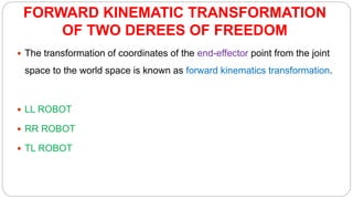
  • 16. FORWARD KINEMATIC TRANSFORMATION OF TWO DEREES OF FREEDOM  The transformation of coordinates of the end-effector point from the joint space to the world space is known as forward kinematics transformation.  LL ROBOT  RR ROBOT  TL ROBOT
  • 17. LL ROBOT  Joints J1 and J2 are linear joints with links of variable length L1 and L2. Let joint J1 be denoted by (x1, y1) and joint J2 (x2, y2)
  • 26. INVERSE KINEMATIC OF TRANSFORMATION OF 2 DEGREE OF FREEDOM
  • 29. Forward and Reverse kinematics transformation for RR robot with 2 DOF with 2D
  • 34. Forward and Reverse kinematics of spherical robot RRL configuration with 2 DOF with 2D
  • 39. FORWARD KINEMATICS FOR 2 DEGREE OF FREEDOM WITH 2 DIMENSIONS
  • 45. INVERSE KINEMATICS FOR 2 DEGREE OF FREEDOM WITH 2 DIMENSIONS
  • 51. FORWARD KINEMATICS FOR 3 DEGREE OF FREEDOM WITH 2 DIMENSIONS
  • 57. INVERSE KINEMATICS FOR 3 DEGREE OF FREEDOM WITH 2 DIMENSIONS
  • 60. Forward and inverse kinematics of manipulators with 4 Degrees of Freedom in 3 Dimension  A 4-Degree of Freedom Manipulator in (3D) Three Dimensions:  The configuration of a manipulator in three dimensions. The manipulator has 4 degrees of freedom: joint I (type T joint) allows rotation about the z axis; joint 2 (type R) allows rotation about an axis that is perpendicular to the z axis; joint 3 is a linear joint which is capable of sliding over a certain range; and joint 4 is a type R joint which allows rotation about an axis that is parallel to the joint 2 axis. Thus, we have a TRL: R manipulator.
  • 62.  Let us define the angle of rotation of joint I to be the base rotation 0; the angle of rotation of joint 2 will be called the elevation angle 4.;  The length of linear joint 3 will be called the extension L (L-represents a combination of links 2 and 3);  and the angle that joint 4 makes with the x — y plane will be called the pitch angle 4.  The position of the end of the wrist, P, defined in the world coordinate system for the robot.
  • 64. ROBOT PROGRAMMING: “Robot Programming is a art of teaching a robot online or offline a series of tasks to be performed with required accuracy, velocity and repeatability.”
  • 66. METHODS OF TRAINING ROBOTS 1. Lead through programming used for servo-controlled robots  Teach-by-guiding  Teach by teach- box methods a. Point-to-point - Move robot to each point in task and record it. b. Continuous-path - Move robot through entire task at normal speed while the robot records its position many times a second.
  • 67. METHODS OF TRAINING ROBOTS 2. Off-line programming used for servo-controlled robots a. Transfer from another robot that already knows how to do task. b. operators write the task programs with step-by-step procedure in some programming language 3. Robot Simulation
  • 68. TEACH BY GUIDING  It is some times also called as lead through programming.  Primarily this method is highly suitable for programming the continuous path robots.  It can be done with simple equipment and controls.  Also, the teaching is performed quickly and is immediately useful.  In the playback mode, the robot repeats the path and operations that were stored in memory during the teach operation.
  • 69. TEACH BY GUIDING  In some systems, it is possible to play back at different speeds than the speed that was used in the teach mode.  Each movement is recorded into the memory for the playback during production.  A person doing the programming has physical contacts with the robot arm, actually gains control and walks the robot's arm through the desired positions.
  • 70. TEACH BY GUIDING  The main concern is on achieving the correct positioning sequences.  Cycle time and speed can be changed later, when necessary.  A dead man’s control should be fitted for the safety reason.  Every operator motion is recorded and played back in the same manner, including unintended motions.
  • 71. DISADVANTAGES TO TEACH-BY-GUIDING:  It is difficult to incorporate sensory information.  It cannot be used in some hazardous situations.  It is not practical in handling large robots.  Since teaching is performed manually, high precision in generating paths con not be achieved.  Synchronization with other operations/device/external sensor may be difficult.
  • 72. TEACHING BY TEACH - BOX METHOD (TEACHING AND PENDANT CONTROL)  Teaching the robot via teach pendants that has toggle switches or contact buttons for controlling the movement of the robot.
  • 73. TEACHING BY TEACH - BOX METHOD (TEACHING AND PENDANT CONTROL)  Moving the robot arm to each specific point manually and pressing a button to record the coordinates of that point do teaching in point- to-point systems.  Encoders, potentiometers, or other means does position measurement.  Large robot arms are often counterbalanced to make manual movement easier. Some large robots have an auxiliary lightweight arm that can be used for training or guidance.
  • 74. TEACHING BY TEACH - BOX METHOD (TEACHING AND PENDANT CONTROL)  The teach pendant can control all axes of the robot arm in terms of position and movement velocity.  Pendant controls are especially useful for large robots that might otherwise be difficult to take through the training cycle.  They are also useful in applications in dangerous environments.
  • 75. TEACHING BY TEACH - BOX METHOD (TEACHING AND PENDANT CONTROL)  In addition, they are more convenient for many purposes other than manual movement, so the use of pendant control has increased in the last few years.  The main disadvantage of this method is that the equipment is tied up in the programming stage.  However because of simplicity this method is widely accepted in industry, especially in PTP applications such as machine loading and unloading, spot welding, simple assembly tasks.
  • 76. ADVANTAGES DISADVANTAGES Shop personnel can readily learn it, does not require deeper programming experience • Logical way to learn Production must be interrupted – Teach pendant have limitations in the amount of decision making logic that can be incorporated into the program – No interface to other computer subsystems in the factory (no CIM).
  • 77. ROBOT PROGRAMMING LANGUAGES This section will review the evolution of robot languages like MH1, WAVE, VAL, PAL, RAIL, HELP, JARS, RPL and MCL
  • 78. 1. MH1 (MECHANICAL HAND ONE)  The first robot language capable of describing operations with programmable commands, developed at MIT by H. A. Ernst The available language commands are:  MOVE - indicating a direction and speed  UNTIL - operate until a specific sensor condition occurs  IF GOTO - branch to a new location in the program on a specific condition  IF CONT - branch to continue action on a specific condition
  • 79. 2. WAVE  WAVE, developed at Stanford University, was the first general purpose robot programming system. The most important features were:  1. Specification of compliance capability in Cartesian coordinates.  2. Coordination of joint motions to provide for continuity of velocities and accelerations through trajectory turning points or via points.  3. Description of end effector positions in Cartesian coordinates.  4. Guarded move capability, so that sensory information could be used to terminate a move when the end effector touched something.
  • 80. 3. AL (ASSEMBLY LANGUAGE)  AL is a high-level programming system for specification of manipulator tasks such as automatic assembly in production line manufacturing.  AL has a considerable effect on other languages and has emerged as one of the leading contenders for a common robotic language.  It was developed at Stanford University in 1974 and has been improved and tested since then.
  • 81. 3. AL (ASSEMBLY LANGUAGE)  It has an ALGOL-like source language, a translator to convert programs into run able code, and a runtime system for controlling manipulators and other devices.  Trajectory calculations are done at compile time and are modified during runtime as necessary.  Two or more objects can be handled as one by the use of AFFIX commands that cause them to appear as one object.
  • 82. 3. AL (ASSEMBLY LANGUAGE)  Force sensing and compliance are implemented by a number of subroutines and by condition monitor statements in the syntax of the language.  There are signal statements and wait statements available when one process must wait for the completion of another process.  These and other statements make possible the coordinated operation of two or more robot arms.  Arm and hand movement commands are available to control moves, velocities, forces, and torques.
  • 83. 4. PLAW (Programming Languages for Arc Welding).  A robot manufacturing company, Komatsu developed it for its series RW Cartesian robots, equipped with arc current and television.  This is a low-level language specifically developed to program an adaptive welding robot.  It primarily serves to simplify the programming of complex operations.  In contrast to AL, this language does not call for the use of a large computer (it can well be implemented with a microcomputer).
  • 84. 4. PLAW (Programming Languages for Arc Welding). PLAW includes the following instructions:  -Robot motion control (point-to-point, using various interpolation techniques)  -Control of welding equipment  -Control of peripherals (by turning ON and OFF the respective channels)  -Control of sensor systems  -Service instructions  -Conditional and unconditional jump instructions. Conditional jump instructions check the status of flags and perform the respective branch action
  • 85. 5. AML (A Manufacturing Language)  AML was developed in 1976 at IBM’s T.J. Watson Research Labs for assembly related tasks.  AML provides a systems environment in which different user robot programming interfaces may be built.  It supports joint space trajectory planning, subject to position and velocity constraints.  Relative and absolute motion can be handled, and sensor monitoring can interrupt motions as necessary.
  • 86. 5. AML (A Manufacturing Language)  The most unique capability of AML is its operations on data aggregates, so that many operations on vectors, rotations, and coordinate frames can be handled as multiple operations in one command.  This capability makes the language more difficult to understand but simplifies programming and control.
  • 87. 6. PASCAL  It is a standard programming language developed by Blazie Pascal for data processing that uses structured statements to organize the program in a modular and efficient way.  The structured statements force the program into separate modules to reduce the number of branches.  Each module is self-contained and can be entered only at the top and exited only at the bottom, so that errors due to branching mistakes are easier to catch and eliminate.
  • 88. 6. PASCAL  Data types are the descriptors that identify elements in the language such as INTEGERS, REAL NUMBERS, and CHARACTERS.  It is a well-known and widely used language, and was chosen as the basis for several robot languages.
  • 89. 7. PAL  Richard Paul, added capabilities to PASCAL to WAVE and the AL language provide a new type of programming language PAL.  This allowed them to take advantage of the proven, well-known PASCAL language and yet provide new capability.  In the PAL data structure, the relationship between the arm and the object can be given explicitly by the use of homogeneous matrix transforms.
  • 90. 7. PAL  Every motion statement in PAL causes the manipulator position and orientation to be specified in an equation representing a closed kinematic chain.  An interesting and potentially valuable capability of PAL is the ease with which unknown points can be picked up from a task and incorporated into the program.  Every motion statement in PAL causes the solution of homogeneous equations that represent the position of the kinematic chain of links and joints in the arm.
  • 91. 8. MCL  MCL was developed in 1978 by McDonnell-Douglas in conjunction with Cincinnati Milacron for an Air Force ICAM Project.  This language is based on APT, the control language for numerically controlled (NC) machine tools used in CAM.  One of its advantages is that a large number of programmers already use APT in CAM applications.  APT has specific constructs to specify POINTS, LINES, PATTERNS, and so on, which are useful in enabling robots to communicate and cooperate with machine tools.
  • 92. 9. RAIL  It was developed by Automatix Inc., for the control of both vision and manipulation.  It contains a large subset of PASCAL commands and can handle a variety of data types.  An interpreter is used to convert the language constructions to machine language commands.  Inspection, arc welding and vision operations are supported by language capabilities. It is run on a powerful Motorola system.
  • 93. 10. RPL  RPL was designed at SRI (Stanford Research Institute) specifically for unskilled programmers, factory production engineers, line foremen, and so on.  It is a low level language.  It has a compiler to produce interpretable code from programs and an interpreter for that code.  The language is implemented as subroutine calls, so that it is modular and flexible in use.
  • 94. 10. RPL  It has been used to control a Unimation PUMA 500 arm and the Machine Intelligence Corporation (MIC) vision module.  Some of the ideas of the LISP language are used but are organized into a FORTRAN-like syntax.  (LISP is a language designed for artificial intelligence use. It is primarily recursive and is especially well adapted to handling lists of information.)
  • 95. 11. ADA  ADA was developed by Ada Lovelace for the Department of Defense (DOD) in 1978.  It has been specified by DOD as the sole system implementation language for the programming of real-time embedded systems.  Chief advantages of ADA are the powerful data structures provided the ability to separate control operations from data operations, and the inherent capability for concurrent operation of many tasks.
  • 96. 11. ADA  Concurrent operation is an important requirement for the efficient use of multiple robots and other equipment.  The ADA is well suited to the control of manufacturing cells using robots.  In addition, ADA is expected to provide code that is easily transferred between computers and can be easily maintained.
  • 97. 12. VAL (important among all languages)  Another language developed by augmentation of an existing language (BASIC) is VAL, developed by Victor Scheinman for the Unimation Corporation in the year 1975.  VAL uses simple words to describe operations to be performed by the robot which leads to real time programming as given below:  Specify and transform the coordinates of positioning points both in a Cartesian system and joint angles.  Edit robot programs written in VAL.  Manage the execution of user programs.
  • 98. 12. VAL  VAL provides for speed control, grasping, arm movement, and signaling in a simple, easy-to-understand framework. Of course, all of these routines are implemented by subroutines written in BASIC and translated by an interpreter.  Higher efficiency could be obtained by the use of a compiled BASIC if necessary, but usually it is sufficient to call precompiled subroutines.  The need for a signal to other robots and machines is handled effectively by the use of the interlock commands such as WAIT, SIGNAL and DELAY, which take action on the occurrence of specific events.
  • 99. 12. VAL  VAL is a low level language and calls there fore for detailed planning of all actions.  VAL provides the executing commands suitable for PUMA robot for the applications in assembly, arc welding, spray painting and material handling.  In VAL, both teaching (Interlock commands) and offline programming can be used in an effective way.  This language is modified into VAL II by adding some more instructions for the operator convenience.
  • 100. MOTION PROGRAMMING – STATEMENTS (VAL) (EXAMPLE)  MOVE P1 // move to variable P1  LEARN P1 //(236,158,65,0,0,0) recorded coordinates  MOVES P1 //(straight line motion) - e.g. MoveL  DMOVE (4, 125) // incremental move joint 4, 125 mm
  • 101. MOTION PROGRAMMING – STATEMENTS (VAL) (EXAMPLE)  DEFINE PATH123 = PATH(P1,P2,P3)  MOVE PATH123 Initial statements: – SPEED 0.5 MPS – EXECUTE PROGRAM1 SPEED 75 –( 75 %) – ARLA H75%, Rapid v xxx.
  • 102. OTHER PROGRAMMING STATEMENTS (EXAMPLE) Interlock and sensor commands – WAIT 20, ON // wait until signal on port 20 is ON – SIGNAL 10, ON // switch signal 10 ON – SIGNAL 10, 6.0 // switch signal 10 analog to 6 volts – OPEN – CLOSE // open and close gripper Computations and program logic – GO TO 150 – IF (logical expression) GO TO 150
  • 103. WELDING INSTRUCTIONS (VAL) (EXAMPLE)  WSET command set the speed, welding voltage and current as a welding condition identified by a number 1 to 4  WSTART starts welding under present welding condition and weaving condition.  WEND inactivates a welding start signal. For example, WEND 0.5 means the welding stops for 0.5 seconds.  CRATERFILL instruction is used when crater filling is required at a welding end of the weldment.